

Quick Start Guide
Before turning the tester on ensure that nothing is connected to the TEST PORT and that the external DC is connected, if required.
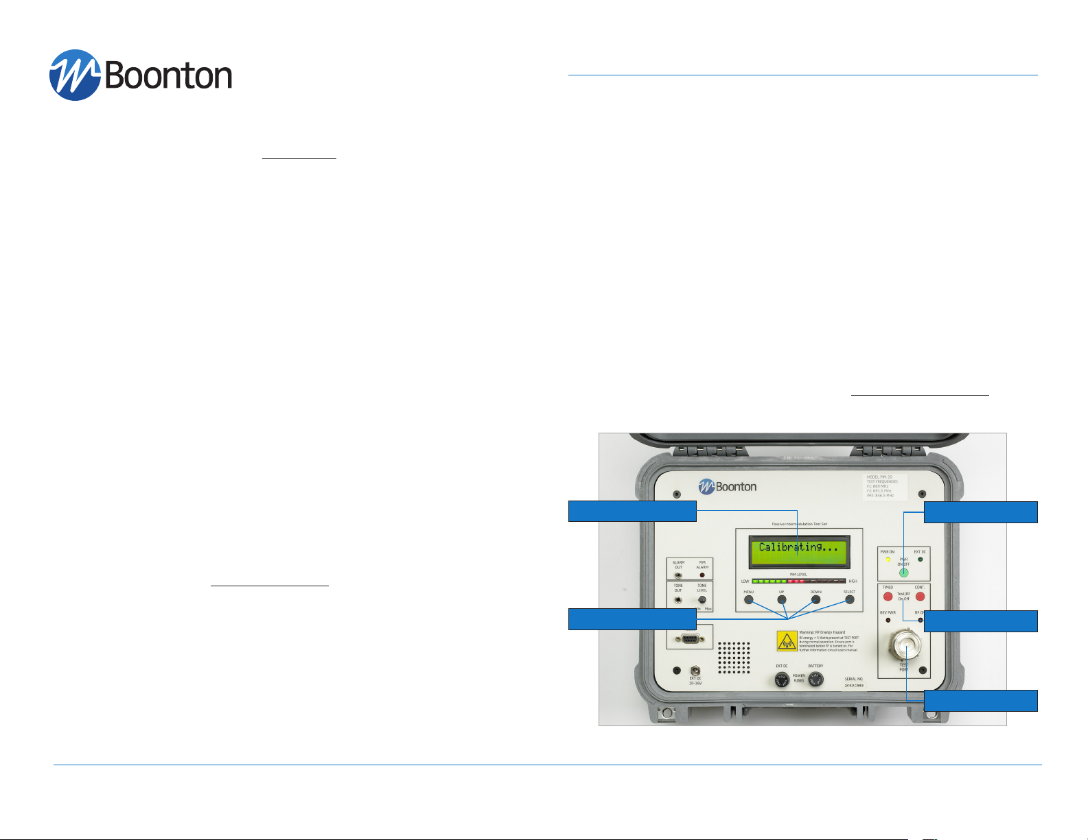
1. Press the green ON / OFF button momentarily to switch the test set on.
a. The digital display will scroll through model, serial number and version
messages and information relating to the frequencies used by the tester.
If no external DC power is connected the message Batt Pwr Only is displayed.
b. The tester will then self-calibrate and display the background noise
PIM value in dBc, this being the default display while the tester is in the
standby RF off mode.
c. Pressing the MENU button now sets the unit to the default RF OFF mode,
from which different menu choices may be selected.
2. Connect the device or cable to be tested to the TEST PORT
a. Press either of the red Test/RF On / Off buttons to turn on the two RF test
tones.
CAUTION: When the RF ON lamp is lit, RF energy is present at the TEST
PORT, so ensure this port is correctly terminated while RF is on.
Note: The two red Test/RF On / Off buttons have different functions; the
TIMED button will turn the RF test tones on for a pre-selected period
of time, typically used to reduce the potential of RF exposure and to
conserve battery life. The CONT button will switch the RF test tones on
continuously and a second button push is required to switch off the RF
tones. The desired TIMED period is set via the SETUP menu.
maximum output of +33 dBm (2 W) per carrier, this is equivalent to -156
dBc to -113 dBc. Each display segment corresponding to approximately
2.7 dB. The changeover from red to green occurs at -140 dBc.
b. The numeric dBm display (in place of the default dBc) is available under
the DISPLAY Menu.
c. An audible indication of PIM level is also provided. Audio tone can be
changed from a sliding tone to beeps via the Setup menu, and audio level
is adjusted by the TONE level control on the front panel.
4. Switching the tester OFF.
a. Once your testing is complete, the tester may be switched off by press-
ing the green PWR ON / OFF button for a minimum of 5 seconds.
LCD Display
Input Keys
Power on / off
Test RF on / off
3. Read the PIM result.
a. In default mode the result is displayed on the digital display as a nega-
tive PIM level in dBc (i.e. level below the RF test tone level). A secondary
bar display is also provided as a quick visual indication. The red and green
indicators display the results in dBm from -123 dBm to -80 dBm. At the
boonton.com 25 Eastmans Rd., Parsippany, NJ 07054 t: (973) 386-9696 f: (973) 386-9191 e: boonton@boonton.com
RF Test Connector

Battery
a. The battery will provide a minimum of 20 minutes of tester operation
when fully charged and the RF carriers are set to a continuous +33 dBm
output. Measurement with timed RF signals extends the operation time
significantly.
b. PIM Test Set can be charged with the AC power supply or with the 12
V vehicle supply. Both are standard accessories that come with PIM 20.
Important: Do not start the car while the 12 V car supply is connected to
PIM 20. Voltage spikes can cause damage to the test system.
Additional Functions
a) Different display and test settings can be accessed via the MENU and
SELECT buttons.
b) Any one of the three menu items can be scrolled with the MENU button
and selected with the SELECT button.
c) The UP and DOWN buttons are only used to increment setting within the
SETUP menu.
d) When working within the menus a Quick Escape back to the default RF
OFF display is possible by holding the MENU button down and pressing
SELECT button 3 times.
MENU STRUCTURE – FIRST LEVEL
Start with default ‘RF OFF’ display, then press MENU once to reach DISPLAY or
twice to reach SETUP.
MENU STRUCTURE – SECOND LEVEL
From DISPLAY press SELECT then press MENU to cycle through the following
items:
1. Rx RSSI Displays receiver sensitivity in dBm,
typically -126 dBm*
2. PIM Displays the units of measurement of PIM
in dBc
Additional Functions & Information
3. F1 Fwd PA Pwr Displays the units of measurement for
power of F1 as 0 dBm
4. F2 Fwd PA Pwr Displays the units of measurement for
power of F2 as 0 dBm
5. F1 Return Loss Displays the units of measurement of F1
return loss as 0 dBm
6. F2 Return Loss Displays the units of measurement of F2
return loss as 0 dBm
7. Battery Volts Displays internal battery volts,12 V*
8. Input Volts (Ext DC) Displays battery volts being applied to EXT
DC connector
9. 4.0 Volts (internal rail) Displays internal 4 Volt Rail, 4 Volts*
10. 5.0 Volts (internal rail) Displays internal 5 Volt Rail, 5 Volts*
EXIT: To return to default RF OFF hold MENU but-
ton down and press SELECT once.
*If measurement deviates from this approximate value, call for service.
From SETUP press SELECT; press MENU to cycle through the following items:
1. F1/F2 Power Lvl Can be adjusted from +20 to +33 dBm using UP/DOWN keys (model dependent).
2. Rev Pwr Alarm Sets threshold at which Reverse Power Alarm
indicator and output triggers, alerts user to
incorrect set up or termination.
3. PIM Alarm Level Sets threshold at which PIM Alarm indicator and output triggers, provides user with
alternate high PIM indications.
4. Tone Type Changes audio tone from Sliding to Beep using UP/DOWN keys.
5. Tone Adj Adjusts frequency of tone to suit user using
UP/DOWN keys.
6. Tx On time Adjusts the RF ‘ON’ period for TIMED RF from
10 to 600 seconds in 10 second intervals
using UP/DOWN keys.
7 Audible Threshold Sets threshold at which audio tone is activated
EXIT: To return to default RF OFF hold MENU but-
ton down and press SELECT twice.
98405900B, Issue 12/2009
 Loading...