

CPS2000
True-Average Connected Power Sensors
PROGRAMMING REFERNCE
MANUAL
P/N: 98408300A
Rev. 20180720

Table of Contents
1 Introduction ............................................................................................................................................ 5
1.1 Scope ................................................................................................................................................ 5
1.2 Referenced Documents ................................................................................................................... 5
1.3 Definitions ........................................................................................................................................ 5
2 Command Syntax .................................................................................................................................... 6
2.1 Command Parameters & Response Types ....................................................................................... 6
2.1.1 Numeric Parameters & Response Types ............................................................................... 6
2.1.2 Boolean Parameters & Response Types ............................................................................... 6
2.1.3 Discrete (Enumeration) Parameters & Response Types ....................................................... 7
2.1.4 ASCII String Parameters & Response Types .......................................................................... 7
2.2 Message Termination & Maximum Length ..................................................................................... 7
2.3 Syntax Conventions .......................................................................................................................... 8
3 Status Reporting ................................................................................................................................... 10
3.1 Status Registers Model .................................................................................................................. 10
3.1.1 Condition Register ............................................................................................................... 10
3.1.2 Transition Filter Registers ................................................................................................... 11
3.1.3 Event Register ..................................................................................................................... 11
3.1.4 Enable Register ................................................................................................................... 11
3.2 Operation Status ............................................................................................................................ 11
3.3 Questionable Status ....................................................................................................................... 13
3.4 Standard Event Status .................................................................................................................... 14
3.4.1 Standard Event Status Register ........................................................................................... 14
3.4.2 Standard Event Status Enable Register ............................................................................... 15
3.5 Status Byte ..................................................................................................................................... 15
3.5.1 Service Request Enable Register ......................................................................................... 16
3.6 Error Codes .................................................................................................................................... 16
4 SCPI Conformance Information ............................................................................................................ 18
5 Measurement Sequence ...................................................................................................................... 19
5.1 Single Measurement Mode ........................................................................................................... 19
5.2 Continuous Measurement Mode ................................................................................................... 20
5.3 Power Measurements .................................................................................................................... 21
5.3.1 Power Measurement Filtering ............................................................................................ 21
5.3.2 Power Measurement Averaging ......................................................................................... 21
5.3.3 Interaction with FETCh[:SCALar][:POWer:AC]?................................................................... 21
6 Example Command Sequences ............................................................................................................ 23
6.1 Taking a Power Measurement with Software Triggering .............................................................. 23
6.2 Continuous Power Measurements ................................................................................................ 23
6.3 Setting Units, Offset, and Correction Frequency ........................................................................... 24
6.4 Retrieving Device Information ....................................................................................................... 24
6.5 Enabling Operation Status Information & Detecting Status Changes ........................................... 25
6.6 Retrieving and Setting Network Configuration .............................................................................. 25

7 Command Reference ............................................................................................................................ 27
7.1 Common Commands (IEE488.2 Commands) ................................................................................. 27
*CLS 27
*ESE 27
*ESE? 27
*ESR? 28
*IDN? 28
*OPC 28
*OPC? 29
*RST 29
*SRE 30
*SRE? 30
*STB? 30
*TST? 31
7.2 Measurement Subsystem (MEASurement Commands) ................................................................ 31
FETCh[:SCALar][:POWer:AC]? ........................................................................................................ 31
READ[:SCALar][:POWer:AC]? ......................................................................................................... 32
FETCh[:SCALar]:TEMPerature? ...................................................................................................... 33
READ[:SCALar]:TEMPerature? ....................................................................................................... 33
7.3 Sense Subsystem (SENSe Commands) ........................................................................................... 34
SENSe:AVERage:COUNt ................................................................................................................. 34
SENSe:AVERage:COUNt? ................................................................................................................ 34
SENSe:AVERage:COUNt:AUTO ....................................................................................................... 35
SENSe:AVERage:COUNt:AUTO? ..................................................................................................... 35
SENSe:CORRection:OFFset[:MAGNitude] ...................................................................................... 36
SENSe:CORRection:OFFset[:MAGNitude]? .................................................................................... 36
SENSe:FILTer:STATe ....................................................................................................................... 37
SENSe:FILTer:STATe? ..................................................................................................................... 37
SENSe:FILTer:TIMe ......................................................................................................................... 38
SENSe:FILTer:TIMe? ....................................................................................................................... 38
SENSe:FREQuency .......................................................................................................................... 39
SENSe:FREQuency? ........................................................................................................................ 39
7.4 Status Subsystem (STATus Commands) ......................................................................................... 40
STATus:OPERation[:EVENt]? .......................................................................................................... 40
STATus:OPERation:CONDition? ..................................................................................................... 40
STATus:OPERation:ENABle............................................................................................................. 41
STATus:OPERation:ENABle? ........................................................................................................... 41
STATus:QUEStionable[:EVENt]? ..................................................................................................... 42
STATus:QUEStionable:CONDition? ................................................................................................ 42
STATus:QUEStionable:ENABle ....................................................................................................... 43
STATus:QUEStionable:ENABle? ..................................................................................................... 43
STATus:PRESet ............................................................................................................................... 44
7.5 System Subsystem (SYSTem Commands) ...................................................................................... 45
SYSTem:ERRor[:NEXT]? .................................................................................................................. 45
SYSTem:COMMunicate[:NETwork]:MAC? ..................................................................................... 45
SYSTem:COMMunicate[:NETwork]:DHCP ...................................................................................... 46
SYSTem:COMMunicate[:NETwork]:DHCP? .................................................................................... 46
SYSTem:COMMunicate[:NETwork]:IP ............................................................................................ 47

SYSTem:COMMunicate[:NETwork]:IP? .......................................................................................... 47
SYSTem:COMMunicate[:NETwork]:SUBNet .................................................................................. 47
SYSTem:COMMunicate[:NETwork]:SUBNet?................................................................................. 48
SYSTem:COMMunicate[:NETwork]:GATeway................................................................................ 48
SYSTem:COMMunicate[:NETwork]:GATeway? .............................................................................. 49
SYSTem:VERSion? .......................................................................................................................... 49
SYSTem:INFO? ................................................................................................................................ 50
SYSTem:INFO:EXTended? .............................................................................................................. 50
7.6 Trigger Subsystem (TRIGger Commands) ...................................................................................... 51
TRIGger:SOURce ............................................................................................................................. 51
TRIGger:SOURce? ........................................................................................................................... 51
TRIGger[:IMMediate] ..................................................................................................................... 52
INITiate[:IMMediate] ..................................................................................................................... 52
INITiate:CONTinuous...................................................................................................................... 53
INITiate:CONTinuous? .................................................................................................................... 53
ABORt 53
7.7 Unit Subsystem (UNIT Commands) ................................................................................................ 54
UNIT:POWer ................................................................................................................................... 54
UNIT:POWer? ................................................................................................................................. 54
8 Revision Notes:
.................................................................................................................................... 55
TABLE OF CONTENTS Page 4
1 Introduction
1.1 Scope
This document is intended to serve as a specification and reference for the instrument commands
supported by the CPS2000 Series True-Average Connected Power Sensors. It is not intended to fully
describe the SCPI language, as that information can be retrieved from the SCPI Consortium and/or IEEE.
However, where appropriate, some information specified in the SCPI specification may be repeated in
this document for clarification purposes.
1.2 Referenced Documents
Ref
Title
Identification/Revision
Source
[1]
Standard Commands for
Programmable Instruments (SCPI)
1999.0
1999 SCPI Consortium
[2]
ANSI/IEEE Standard 488.2-1987
488.2-1987
The Institute of Electrical and
Electronics Engineers, Inc.
1.3 Definitions
Term/Abbreviation
Definition
SCPI
Standard Commands for Programmable Instruments
Command
A SCPI instruction consisting of keywords, parameters, and punctuation.
Query
A special type of command used to retrieve data and information from the
device.
1-1 INTRODUCTION Page 5

2 Command Syntax
SCPI Commands and queries are sent as standard ASCII strings through various interfaces. Following
standard SCPI ’99 syntax, the CPS2000 SCPI commands are made up of keywords, parameters, and
various punctuation.
Commands consist of one or more keywords, separated by colon “:” characters, with zero or more
parameters starting with a <space> character. In general, commands are not acknowledged by any sort
of response message.
Queries follow the same syntax as general commands, but end with a question mark “?” character.
Upon receiving a query command, the device will return data according to the specified query. Queries
occasionally also have parameters, located after the “?” character.
2.1 Command Parameters & Response Types
Several commands take one or more parameters as part of the command, while query commands
return data in particular formats. SCPI defines different data formats for use in these parameters and
responses including numerical values, Boolean values, enumerations, and strings.
Within this document, expected data types are specified along with each command’s specification.
For more information on the data types supported by SCPI, refer to the SCPI ’99 specification and IEEE
488.2.
2.1.1 Numeric Parameters & Response Types
Numeric parameters and response types are integer or floating point numerical values that can be
positive or negative, depending on the command or query. Numerical values follow the formatting
specifications of the NR1 format defined in IEEE 488.2. Following SCPI syntax, numerical values are
transmitted as ASCII characters.
Denoted as:
<numeric_value>
For some commands, an additional unit suffix component is supported to denote units for a parameter.
Suffix components are always optional, but when supported by a command, are documented with that
command. When included, units suffix components are denoted with a numerical value as:
<numeric_value><suffix>
2.1.2 Boolean Parameters & Response Types
Boolean parameters and response types are binary variables having two possible values. Boolean
parameters and response types can be denoted using:
2-1 COMMAND SYNTAX Page 6

ON or OFF
-or-
1 or 0
Where ON is equivalent to 1 and OFF is equivalent to 0.
Either format is accepted. Within this document, Boolean parameters and response types generally use
the ON or OFF formatting to describe the meaning of each option.
Denoted as:
<Boolean>
2.1.3 Discrete (Enumeration) Parameters & Response Types
Discrete parameters and response types are values that have a specific set of supported options. The
possible options for a command is documented with the command, and any options not specified in this
document can be assumed as unsupported options.
Denoted as:
<Option1|Option2|Option3>
2.1.4 ASCII String Parameters & Response Types
The CPS2000 series of devices also supports ASCII string parameters and response types. Some
commands return textual information and/or take text as a parameter. In general, ASCII string
parameters and response types support the 8-bit ASCII character set. Any other character formatting is
not supported.
Denoted as:
<string-label>
where “label” is a descriptive label for the expected contents of the string
2.2 Message Termination & Maximum Length
SCPI commands and responses are terminated upon receipt of a message terminator. The CPS2000
series of power sensors make use of a new-line (\n) character as its message terminator.
Additionally, for the CPS2000 series of devices, the maximum length allowed for a single command is
256 bytes.
2-2 COMMAND SYNTAX Page 7

2.3 Syntax Conventions
Specific syntax conventions are as follows:
CHARACTERS
DESCRIPTION
EXAMPLE
|
A vertical pipe character between
keywords and/or parameters indicates
alternate choices.
UNIT:POWer <DBM|W>
DBM and W are both accepted, but
alternate choices.
[ ]
Indicates that the enclosed keywords are
optional when composing a command.
The enclosed keywords or parameters
will be assumed even if omitted.
INITiate[:IMMediate]
:IMMediate is optional, and the
command is assumed even if instead
sent as INITiate
:
Separates keywords within a complete
command tree. Keywords further to the
right within a command represents
commands lower in the SCPI command
tree, where keywords to the left
represent more base, high-level
subsystems of a command tree.
INITiate:CONTinuous
INITiate and CONTinuous are
separate keywords, but are combined to
make up a single command using the :
character.
,
Separates adjacent parameters or
responses when more than one
parameter or response is expected for a
command.
SYSTem:ERRor[:NEXT]?
returns
<numeric_value>,<string-description>
Corresponding to 2 components of the
response – a numerical value and a
string value.
< >
Indicates that the enclosed content is not
to be used literally in a command, but
just represents and describes the
necessary content.
SENSe:FREQuency
<numerical_value>
Where <numerical_value>
corresponds to a user-filled parameter
for the SENSe:FREQuency command.
2-3 COMMAND SYNTAX Page 8

CHARACTERS
DESCRIPTION
EXAMPLE
Upper-case
keyword
characters
Indicates the minimum set of characters
for a command.
SENSe:FREQuency?
In this command, only the SENS and
FREQ characters are required. As such,
an equivalent command would be:
SENS:FREQ?
Lower-case
keyword
characters
Additional, optional characters for a
command. These characters can be
included or omitted from a command
string. If any are omitted, all lower-case
keyword characters must be omitted.
INITiate:CONTinuous
In this command, only the INIT and
CONT characters are required. As such,
an equivalent command would be:
INIT:CONT
Whitespace
Generally ignored as long as they are not
included within a command’s keywords.
A single <space> character is required
to separate parameters from a
command’s keywords.
2-4 COMMAND SYNTAX Page 9
3 Status Reporting
In general, the status registers are always-positive (unsigned) 16-bit registers.
Although SCPI supports the use of transition filters, the CPS2000 series of devices does not make use of
any transition filters. Additionally, the SCPI specification includes an optional feature for remapping bits
within the Operation and Questionable Status Registers. The CPS2000 series of devices does not support
that feature.
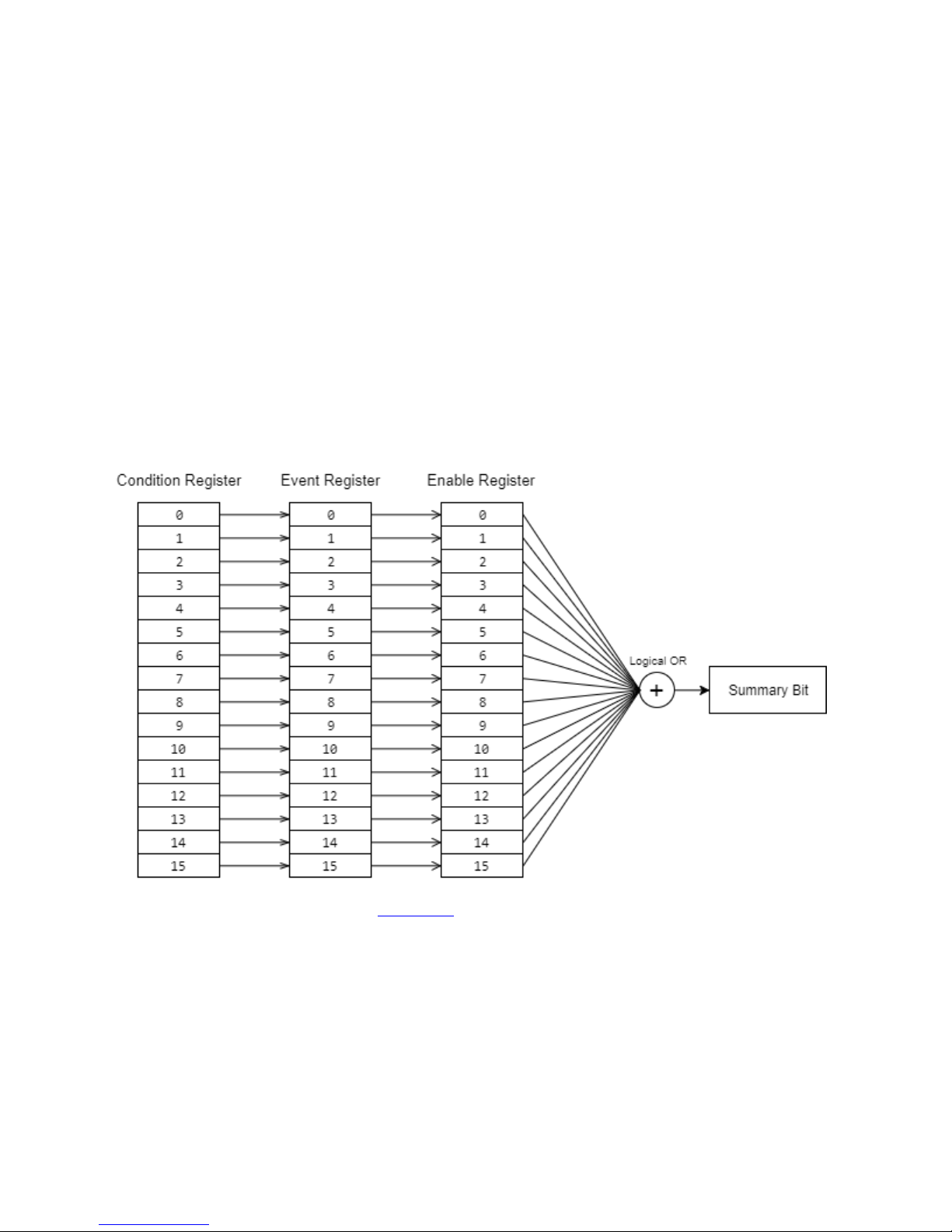
3.1 Status Registers Model
Each of the status registers supported by the CPS2000 series of devices follows a particular model
according to the SCPI specification. Each Status described in the following sections has a set of 4
associated registers: a Condition register, Transition Filter registers, an Event register, and an Enable
register. For the CPS2000 series of devices, the Transition Filter registers are not used.
For an example of using registers, see Section 6.5.
3.1.1 Condition Register
The Condition Register component of a status serves as the source of information for the rest of the
Status Registers Model. This register is updated in real-time and is read-only. Bits set within the
Condition Register describe conditions that occur in real-time.

3.1.2 Transition Filter Registers
Although the SCPI specification defines a set of Transition Filter Registers, the CPS2000 devices do not
include support for any transition filters.
Instead, anytime a bit transitions from 0 to 1 in the Condition Register occcurs, the corresponding bit in
the Event Register is set to 1.
3.1.3 Event Register
The Event Register component of a Status consists of bits assigned to events. Bits in the Event Register
are latched and only cleared by a query or a *CLS command. The Event Register is read-only.
3.1.4 Enable Register
The Enable Register component of a Status contains bits that define what bits in the Event Register
generate a ‘1’ for the summary bit in the Status Byte. When a bit in the Enable Register is set to a ‘1’, a
‘1’ for the corresponding Event Register bit will result in a ‘1’ for the summary bit in the Status Byte.
3.2 Operation Status
The Operation Status provides general operational status information for the instrument. It follows the
Status Registers Model described in section 3.1 and includes a Condition Register, Event Register, and
Enable Register.
Configuration of each of these registers is performed with the STATus:OPERation SCPI commands as
described in section 7.4 Status Subsystem (STATus Commands).
The Operation Status Condition Register is a 16-bit unsigned register and has the following definition:
BIT
DESCRIPTION
0
Calibrating bit
Set when the instrument is performing a calibration.
1
Settling bit
Not Used
2
Ranging bit
Not Used
3
Sweeping bit
Not Used
4
Measuring bit
Set when the instrument is in the MEASURING state and is
taking an actual power measurement.
See Section 5 Measurement Sequence for more details.
3-1 STATUS REPORTING Page 11

BIT
DESCRIPTION
5
Waiting for Trigger bit
Set when the instrument is in the
WAITING_FOR_TRIGGER state.
See Section 5 Measurement Sequence for more details.
6
Waiting for ARM bit
Not Used
7
Correcting bit
Not Used
8–12
Not Used
13
Instrument Summary bit
Not Used
14
Programming Running bit
Not Used
15
Always Zero
3-3 STATUS REPORTING Page 12

3.3 Questionable Status
The Questionable Status provides information indicating the quality of various aspects of the device. A
bit set within the Questionable Status Condition Register indicates that the associated data is of
questionable quality due to some condition affecting that parameter. For example, if the Temperature
bit is set, that means the accuracy of the Temperature reading is of questionable quality.
The Questionable Status follows the Status Registers Model described in section 3.1 and includes a
Condition Register, Event Register, and Enable Register.
Configuration of each of these registers is performed with the STATus:QUEStionable SCPI commands
as described in section 7.4 Status Subsystem (STATus Commands).
The Questionable Status Condition Register is a 16-bit unsigned register with the following definition:
BIT
DESCRIPTION
0
Questionable Voltage bit
Not Used
1
Questionable Current bit
Not Used
2
Questionable Time bit
Not Used
3
Questionable Power bit
Set to a 1 when the latest power measurement is of
questionable quality.
4
Questionable Temperature bit
Set to a 1 when the latest temperature value is of
questionable quality.
5
Questionable Frequency bit
Not Used
6
Questionable Phase bit
Not Used
7
Questionable Modulation bit
Not Used
8
Questionable Calibration bit
Set to a 1 when the device calibration is of questionable
quality.
9
Not Used
10
Not Used
11
Not Used
12
Not Used
3-4 STATUS REPORTING Page 13

BIT
DESCRIPTION
13
Instrument Summary bit
Not Used
14
Command Warning bit
Not Used
15
Always Zero
3.4 Standard Event Status
The Standard Event Status is a register described by IEEE 488.2. In general, it contains various error
status information and basic operation information. From the full Status Registers Model, the Standard
Event Status only consists of 2 registers: one containing the real-time status of standard events, and one
to enable bits for generation of the Standard Event Status Summary Bit.
3.4.1 Standard Event Status Register
The Standard Event Status Register is read-only and contains the real-time status of various events.
The Standard Event Status Register’s value can be obtained using the *ESR? query.
The Standard Event Status Register’s value is cleared when:
a. Sending a *CLS command or
b. Querying the value using the *ESR? query
The Standard Event Status Register is an 8-bit unsigned register with the following definition:
BIT
DESCRIPTION
0
Operation Complete bit
When 1, indicates the last requested operation was
completed.
1
Request Control bit
Not Used
2
Query Error bit
Not Used
3
Device Dependent Error bit
When 1, indicates a device error occurred.
4
Execution Error bit
When 1, indicates an execution error occurred.
5
Command Error bit
When 1, indicates a command syntax error occurred.
6
User Request bit
Not Used
3-5 STATUS REPORTING Page 14

BIT
DESCRIPTION
7
Power On bit
Not Used
3.4.2 Standard Event Status Enable Register
The Standard Event Status Enable Register is read/write and configures which bits of the Standard Event
Status Register constitute a 1 in the Standard Event Status Summary Bit. If a bit of the Standard Event
Status Enable Register is configured as 1 and the corresponding bit of the Standard Event Status Register
is also 1, the Standard Event Status Summary Bit will be set to a 1.
The Standard Event Status Enable Register’s value can be configured using the *ESE command and can
be retrieved using the *ESE? query.
The Standard Event Status Enable Register’s value is cleared when:
a. Power cycling the device or
b. Sending a *ESE 0 command.
3.5 Status Byte
The Status Byte contains summary information about the state of the device. It contains bits
corresponding to the Questionable Status Summary, Standard Event Status Summary and the Operation
Status Summary, which are set as configured using the Status Registers Model (see section 3.1 for more
details).
The value of the Status Byte is obtained using the *STB? query.
The Status Byte definition is as follows:
BIT
DESCRIPTION
0
Not Used
1
Not Used
1 if an error/event is present in the Error/Event queue, or
0 if no error/event is present.
2
Errors/events are retrievable using the *ESR? command.
3
Questionable Status Summary bit
4
Message Available bit (MAV)
Set to a 1 when a message is available, such as when a
power measurement is complete and ready for retrieval.
3-6 STATUS REPORTING Page 15

BIT
DESCRIPTION
5
Standard Event Status Summary bit
6
Service Request bit
Summary status bit for the Status Byte itself. Configuring
the behavior of this bit is performed using the *SRE
command.
7
Operation Status Summary bit
3.5.1 Service Request Enable Register
The Status Byte also has an Enable Register for configuring the Service Request bit (bit 6 of the Status
Byte). This register works similar to the other enable registers, configuring which bits of the Status Byte
constitute a 1 in the Service Request bit.
The Service Request Enable Register can be configured using the *SRE command.
3.6 Error Codes
The list of SCPI error codes that are reported by the CPS2000 series of devices is as follows:
ERROR
CODE
DESCRIPTION
-100
General command error
-101
Invalid character
-102
Syntax error
-103
Invalid separator
-104
Data type error
-105
GET (query) not allowed
-108
Parameter not allowed
-109
Missing parameter
-110
Command header error
3-7 STATUS REPORTING Page 16

ERROR
CODE
DESCRIPTION
-115
Unexpected number of parameters
-120
Numeric data error
-130
Suffix error
-140
Character data error
-150
String data error
-160
Block data error
-170
Expression error
-200
General execution error
-220
General parameter error
-222
Data out of range error
-230
Data corrupt or stale error
-240
General hardware error
-241
Hardware missing
-242
Hardware malfunction
-300
Generic, device-specific error
-350
Queue overflow
3-8 STATUS REPORTING Page 17
3-8 STATUS REPORTING Page 17

4 SCPI Conformance Information
The CPS2000 series of devices complies with the specifications of SCPI version 1999.0. You can
determine the exact SCPI version that a device implements using the SYSTem:VERSion? Query.
The following commands are device-specific for the CPS2000 series of devices, and are not included in
the 1999.0 revision of the SCPI standard:
SENSe:FILTer:STATe
SENSe:FILTer:STATe?
SENSe:FILTer:TIMe
SENSe:FILTer:TIMe?
SYSTem:COMMunicate[:NETwork]:MAC?
SYSTem:COMMunicate[:NETwork]:DHCP
SYSTem:COMMunicate[:NETwork]:DHCP?
SYSTem:COMMunicate[:NETwork]:IP
SYSTem:COMMunicate[:NETwork]:IP?
SYSTem:COMMunicate[:NETwork]:SUBNet
SYSTem:COMMunicate[:NETwork]:SUBNet?
SYSTem:COMMunicate[:NETwork]:GATeway
SYSTem:COMMunicate[:NETwork]:GATeway?
SYStem:INFO?
SYStem:INFO:EXTended?
4-1 SCPI CONFORMANCE INFORMATION Page 18

5 Measurement Sequence
The CPS2000 series of devices follows certain sequences when taking power measurements, depending
on the configuration. Two different measurement modes are supported: a Single Measurement Mode
and a Continuous Measurement Mode. The default measurement mode of the device is Single
Measurement Mode.
5.1 Single Measurement Mode
The Single Measurement Mode sequences involve initiation, triggering, and then actual construction of
the measurement. The default state in this mode is IDLE, and the device only moves to the
WAITING_FOR_TRIGGER state when an INITiate[:IMMediate] command is received. When a
measurement is complete, the device moves back into the IDLE state and again waits for an
INITiate[:IMMediate] command.
If the power measurement filter is enabled (see SENSE:FILTer), a measurement is not considered
complete as is not returned until the power measurement filter is filled. Once the filter is filled according
to the configuration set using the SENSe:FILTer:TIMe command, the measurement is treated as
complete, and if a FETCh? command has been received, the measurement is returned.
5-1 MEASUREMENT SEQUENCE Page 19

STATE
DESCRIPTION
IDLE
Device is idle, and no power measurement has been
started or initiated.
WAITING_FOR_TRIGGER
A power measurement is initiated, but waiting for a
trigger event.
MEASURING
The power measurement is in-progress.
If a FETCh? command is received while the device is in
this state, the resulting power measurement will be
returned to the caller after the measurement is
complete.
5.2 Continuous Measurement Mode
Continuous Measurement Mode follows a sequence similar to the Single Measurement Mode, except
that the IDLE state is skipped after Continuous Measurement Mode is enabled. Instead of returning to
IDLE after the MEASURING state, the device automatically initiates another measurement and moves
into the WAITING_FOR_TRIGGER state.
If the device is in this state, the ABORt command will immediately move the device back into the IDLE
state and automatically disable Continuous Measurement Mode.
5-2 MEASUREMENT SEQUENCE Page 20

5.3 Power Measurements
Internally to the device, power measurements are retrieved at a rate of 1000 Hz, or 1 sample per
millisecond. Once obtained, power measurement samples are processed using either the Power
Measurement Boxcar Filter (termed Power Measurement Aperture) or using Power Measurement
Averaging. These methods are mutually exclusive – Filtering cannot be applied at the same time as
Averaging. While similar, these two different methods of smoothing data also have subtle differences as
described in the following sections.
5.3.1 Power Measurement Filtering
The CPS2000 series of devices support filtering of power measurements using an aperture, controllable
with the SENSe:FILTer:STATe and SENSe:FILTer:TIMe commands. When enabled, power
measurements will go through the power measurement filtering process before being made available
for retrieval.
Due to the nature of the aperture filter, when first enabled, the filter must be filled with data before
data measurements become available. For example, if the Filter is set to ON with a Filter Time of 50ms,
valid power measurements will not be available until 50ms after the filter is first enabled. Following this
initial delay, power measurements are then immediately available with no additional impact to the rate
at which data can be retrieved.
When using the Power Measurement Filter, it is recommended that the device be placed into
Continuous Measurement Mode using the INITiate:CONTinuous command.
5.3.2 Power Measurement Averaging
As an alternative to the Power Measurement Aperture, the CPS2000 series of devices also support basic
averaging of data. Averaging of power measurements is controllable with the
SENSe:AVERage:COUNt:AUTO and SENSe:AVERage:COUNt commands. Generally, when
SENSe:AVERage:COUNt:AUTO (auto averaging) is set to OFF, averaging, according to the sample-
count set with SENSe:AVERage:COUNt, is enabled. When SENSe:AVERage:COUNt:AUTO (auto
averaging) is set to ON, averaging is generally not used by the device, and Filtering is used instead.
Unlike the Power Measurement Aperture, Power Measurement Averaging averages a new set of power
measurements together for each new measurement sequence, and therefore continuously affects the
rate at which data is available. The higher the value set using SENSe:AVERage:COUNt, the slower the
measurement rate.
5.3.3 Interaction with FETCh[:SCALar][:POWer:AC]?
Filtering and averaging have implications on the behavior of the FETch? command that may not be
immediately obvious. They are explained below:
5-3 MEASUREMENT SEQUENCE Page 21

Filtering
If Filtering is enabled, the first time FETCh? is sent (assuming the device is in the MEASURING state)
the power measurement will be returned after a delay approximately equivalent to the filter time
(aperture) window. Subsequence requests using FETCh? will incur no delay, but will instead
immediately return with the latest power measurement.
Averaging
If the manual averaging count is enabled, every FETCh? request made while the device is in the
MEASURING state will be responded to after a delay approximately equal the averaging count, in
milliseconds.
Frequency Changes
Additionally, a delay is incurred when frequency is changed using the SENSe:FREQuency command.
Whenever the frequency is changed, the active measurement is cancelled, the filter and averaging
buffers are reset, and a slight delay occurs due to internal calibration adjustments.
Note!
Due to the delays described above, care must be taken when setting large filter times or
averaging counts to ensure timeouts do not occur while waiting on a FETCh? response. If
a filter time or averaging count is set to the maximum value of 2000 and a frequency
change occurs, FETCh? may wait to return the power measurement for as long as 2 to 2.5
seconds.
5-4 MEASUREMENT SEQUENCE Page 22

6 Example Command Sequences
6.1 Taking a Power Measurement with Software Triggering
The following command sequence sets the trigger source for software triggering, initiates a power
measurement, triggers the measurement, waits for the device to take the measurement, and then
retrieves the actual power measurement.
TRIGger:SOURce BUS
Set the Trigger Source to Software Trigger mode
INITiate:IMMediate
Initiate a measurement
TRIGger:IMMediate
Send the software trigger
*STB? 0
Check the MAV bit of the status byte
*STB? 16
FETCh:SCALar:POWer:AC?
-3.554235e+01
Fetch the power measurement
6.2 Continuous Power Measurements
The following command sequence sets up continuous triggering mode with a trigger source of
immediate and then retrieves actual power measurements.
TRIGger:SOURce IMMediate
Set the Trigger Source to Immediate
INITiate:CONTinuous ON
Enable Continuous Mode
*STB?
16
Check the MAV bit of the status byte
FETCh:SCALar:POWer:AC?
-2.389993e+01
Fetch the power measurement
*STB? 16
FETCh:SCALar:POWer:AC?
-2.389983e+01
6-1 EXAMPLE COMMAND SEQUENCES Page 23

*STB? 16
FETCh:SCALar:POWer:AC?
-2.389981e+01
6.3 Setting Units, Offset, and Correction Frequency
This command sequence configures Power Units, power measurements Offset, and the device’s
Correction Frequency.
UNIT:POWer DBM
Set Power units to dBm
SENSe:CORRection:OFFset:MAGNitude
12.3
Set Offset to 12.3 dBm
SENSe:FREQuency 1500000000
Set Frequency to 1.5 GHz
6.4 Retrieving Device Information
This command sequence retrieves general device information.
*IDN? Boonton,CPS2008,000025,1.0.0
Query basic information
SYSTem:INFO:EXTended? 0
cal_date=2017-11-18;
Request first group of extended
information
6-2 EXAMPLE COMMAND SEQUENCES Page 24

6.5 Enabling Operation Status Information & Detecting Status Changes
The following command sequence configures the Operation Status Register to enable bit 4 (measuring
status bit) as a bit that sets the Operation Status Summary bit of the Status Byte, and then polls the
register values until the Operation Status Summary bit is set. This sequence assumes the device has
been configured for continuous triggering mode with an immediate trigger source.
STATus:OPERation:ENABle 16
Enable the Measuring bit in the Operation Status Enable
Register
STATus:OPERation:CONDition?
16
Query the Operation Status Condition Register – Device
indicates MEASURING state
STATus:OPERation:EVENt? 16
Query the Operation Status Event Register – Device indicates
Measuring event
*STB? 128
Request the Status Byte, which now has bit 7 set since the
Measuring bit in the Operation Status Event Register was set
to 1.
STATus:OPERation:EVENt? 0
Query the Operation Status Event Register – Event Register is
cleared due to previous command
6.6 Retrieving and Setting Network Configuration
The following command sequence retrieves the active network configuration from the device and then
sets a static IP network configuration.
SYSTem:COMMunicate:NETwork:DHCP? ON
Query DHCP Enabled state
SYSTem:COMMunicate:NETwork:IP?
192.168.1.45
Query device IP Address
SYSTem:COMMunicate:NETwork:SUBNET?
255.255.255.0
Query device Subnet Address
SYSTem:COMMunicate:NETwork:GW?
192.168.1.1
Query device Gateway
SYSTem:COMMunicate:NETwork:DHCP OFF
Turn DHCP Off (use static IP
configuration)
6-3 EXAMPLE COMMAND SEQUENCES Page 25

SYSTem:COMMunicate:NETwork:IP
192.168.1.101
Set device’s static IP Address
SYSTem:COMMunicate:NETwork:SUBNET
255.255.255.0
Set device’s static Subnet Address
SYSTem:COMMunicate:NETwork:GW 192.168.1.1
Set device’s static Gateway Address
SYSTem:COMMunicate:NETwork:DHCP? OFF
Query DHCP Enabled state
SYSTem:COMMunicate:NETwork:IP?
192.168.1.101
Query device IP Address
SYSTem:COMMunicate:NETwork:SUBNET?
255.255.255.0
Query device Subnet Address
SYSTem:COMMunicate:NETwork:GW?
192.168.1.1
Query device Gateway
6-4 EXAMPLE COMMAND SEQUENCES Page 26

7 Command Reference
7.1 Common Commands (IEE488.2 Commands)
*CLS
Syntax
*CLS
Parameters
None
Response
None
Description
Clear Status command.
Clears device status data structures. The Questionable Status Event Register,
Operation Status Event Register, Standard Event Status Register, and Status
Byte, and the Error/Event queue are all cleared by this command.
*ESE
Syntax
*ESE <numerical_value>
Parameters
<numerical_value>
A numerical value serving as a bitmask for the bits that will be enabled.
Range
0 – 255
Response
None
Description
Standard Event Status Enable command.
Sets the Standard Event Status Enabled register.
See section 3.4 Standard Event Status.
*ESE?
Syntax
*ESE?
Parameters
None
Response
<numerical_value>
The value of the Standard Event Status Enable register
Description
Standard Event Status Enable query.
Retrieves the value of the Standard Event Status Enable register.
See section 3.4 Standard Event Status.
7-1 COMMAND REFERENCE Page 27

*ESR?
Syntax
*ESR?
Parameters
None
Response
<numerical_value>
The value of the Standard Event Status Register.
Description
Standard Event Status Register query.
Retrieves the value of the Standard Event Status Register.
NOTE:
After returning the value of the Standard Event Status register, the register
value is cleared. The data in the Standard Event Status register is latched until
queried using this command, after which the value is reset.
*IDN?
Syntax
*IDN?
Parameters
None
Response
<string-manufacturer>,<string-model>,<string-serial
number>,<string-firmware version>
Basic identification information, including manufacturer, device model, device
serial number, and device firmware version.
Description
Identification query.
Retrieves basic identity information for the device.
Example
Request:
*IDN?
Response:
Boonton,CPS2008,000025,1.0.0
*OPC
Syntax
*OPC
Parameters
None
Response
None
Description
Operation Complete command.
7-2 COMMAND REFERENCE Page 28

Sets bit 0 of the Standard Event Status register after all pending operations
have completed.
*OPC?
Syntax
*OPC?
Parameters
None
Response
<Boolean>
Description
Operation Complete query.
Returns the ASCII character 1 when all pending operations have finished.
*RST
Syntax
*RST
Parameters
None
Response
None
Description
Reset command.
Resets the device to a known state.
Specifically, the following settings and configuration options are reset:
Command / Setting
Reset to Default of
SENSe:AVERage:COUNt
50
SENSe:AVERage:COUNt:AUTO
ON
SENSe:CORRection:OFFset[:MAGNitude]
0.0
SENSe:FILTer:STATe
ON
SENSe:FILTer:TIMe
50
SENSe:FREQuency
1GHZ
TRIGger:SOURce
IMMediate
INITiate:CONTinuous
OFF
UNIT:POWer
DBM
7-2 COMMAND REFERENCE Page 29
7-3 COMMAND REFERENCE Page 29

*SRE
Syntax
*SRE
Parameters
<numerical_value>
A numerical value serving as a bitmask for the bits that will be enabled.
Range
0 – 255
Response
None
Description
Service Request Enable command.
Sets the value of the Service Request Enable register.
See section 3.5 Status Byte for more information.
*SRE?
Syntax
*SRE?
Parameters
None
Response
<numerical_value>
The value of the Service Request Enable register.
Description
Service Request Enable query.
Returns the value of the Service Request Enable register.
See section 3.5 Status Byte for more information.
*STB?
Syntax
*STB?
Parameters
None
Response
<numerical_value>
The device Status byte.
Description
Read Status Byte query.
Returns the value of the device Status byte, including the master summary
status bit.
See section 3.5 Status Byte for more information.
7-4 COMMAND REFERENCE Page 30

*TST?
Syntax
*TST?
Parameters
None
Response
<numerical_value>
0
All tests passed
1
One or more tests failed
Description
Self-Test query.
Initiates an internal self-test and returns the result of that test.
7.2 Measurement Subsystem (MEASurement Commands)
FETCh[:SCALar][:POWer:AC]?
Syntax
FETCh[:SCALar][:POWer:AC]?
Parameters
None
Response
<numerical_value>
A numerical power measurement in units as configured using the
UNIT:POWer command.
Description
Retrieves a power measurement.
The FETCh? query returns data any time the last power measurement
reading is valid.
Data becomes valid after completion of a measurement sequence, as
described in section 5 (Measurement Sequence).
If the device is in the IDLE state and a measurement has not been initiated,
the FETCh? query will not return any data and will instead generate an error
with code -230.
If a measurement has been initiated, but not triggered, the FETCh? query
will not return any data and will instead generate an error with code -230.
If a measurement has been initiated and triggered (either by a software
trigger or due to a trigger source of IMMediate), the FETCh? query will
return the power measurement when it is ready. If the power measurement
is delayed due to a frequency change, averaging time, or filtering, the power
measurement will be returned after that delay.
7-5 COMMAND REFERENCE Page 31

For more details regarding the measurement cycles and when power
measurements are available, see section 5 Measurement Sequence.
Example
Request:
FETCh:SCALar:POWer:AC?
Response:
-3.566245e+01
READ[:SCALar][:POWer:AC]?
Syntax
READ[:SCALar][:POWer:AC]?
Parameters
None
Response
<numerical_value>
A numerical power measurement in units as configured using the
UNIT:POWer command.
Description
Initializes a measurement sequence and then retrieves a power
measurement.
This command is equivalent to sending the following sequence of commands,
with a Trigger Source of IMMediate:
ABORt
INITiate:IMMediate
FETCh:SCALar:POWer:AC?
Since the READ? query aborts any existing measurements and then initiates a
new measurement, it should not be used for continuous data acquisition
(Continuous Measurement Mode) – in this case, use FETCh? queries instead.
For more details regarding the measurement cycles, see section 5
Measurement Sequence.
Example
Request:
READ:SCALar:POWer:AC?
Response:
-3.187887e+01
7-6 COMMAND REFERENCE Page 32

FETCh[:SCALar]:TEMPerature?
Syntax
FETCh[:SCALar]:TEMPerature?
Parameters
None
Response
<numerical_value>
The current temperature reading from the device, in degrees Celsius.
Description
Retrieves the latest temperature measurement from the device.
Unlike power measurements, temperature readings are always available and
considered valid, with no measurement initiation, triggering, or sequencing
required.
Example
Request:
FETCh:SCALar:TEMPerature?
Response:
3.448959e+01
READ[:SCALar]:TEMPerature?
Syntax
READ[:SCALar]:TEMPerature?
Parameters
None
Response
<numerical_value>
The current temperature reading from the device, in degrees Celsius.
Description
Retrieves the latest temperature measurement from the device.
Unlike power measurements, temperature readings are always available and
considered valid, with no measurement initiation, triggering, or sequencing
required.
Example
Request:
READ:SCALar:TEMPerature?
Response:
3.448959e+01
7-7 COMMAND REFERENCE Page 33

7.3 Sense Subsystem (SENSe Commands)
SENSe:AVERage:COUNt
Syntax
SENSe:AVERage:COUNt <numerical_value>
Parameters
<numerical_value>
The averaging count to set. Only supports integer values.
Range
1 – 2000
Default
Value
50
Response
None
Description
Sets the averaging count in use by the device for power measurements.
NOTE:
Sending this command automatically disables automatic averaging.
For details regarding the measurement cycles and averaging, see section 5
Measurement Sequence and section 5.3.2 Power Measurement Averaging.
Example
SENSe:AVERage:COUNt 10
SENSe:AVERage:COUNt?
Syntax
SENSe:AVERage:COUNt?
Parameters
None
Response
<numerical_value>
The averaging count in use by the device.
Description
Retrieves the averaging count in use by the device for power measurements.
Example
Request:
SENSe:AVERage:COUNt?
Response:
5
7-8 COMMAND REFERENCE Page 34

SENSe:AVERage:COUNt:AUTO
Syntax
SENSe:AVERage:COUNt:AUTO <Boolean>
Parameters
<Boolean>
1 to enable automatic averaging by the device.
0 to disable automatic averaging by the device.
Default
Value
1
Response
None
Description
Enables or disables automatic averaging for power measurements taken by
the device.
When set to 1, averaging of power measurements is automatically handled
by the device and the averaging count is ignored.
When set to 0, averaging of power measurements is enabled and follows the
setting configured using the SENSe:AVERage:COUNt command.
Additionally, when this command is sent with an 0 parameter, the Filter State
is automatically disabled (set to 0).
For more details regarding the measurement cycles and averaging, see
section 5 Measurement Sequence and section 5.3.2 Power Measurement
Averaging.
Example
SENSe:AVERage:COUNt:AUTO 1
SENSe:AVERage:COUNt:AUTO?
Syntax
SENSe:AVERage:COUNt:AUTO?
Parameters
None
Response
<Boolean>
1 if automatic averaging is in use by the device.
0 if automatic averaging is not in use by the device.
Description
Retrieves whether or not automatic averaging for power measurements is in
use by the device.
Example
Request:
SENSe:AVERage:COUNt:AUTO?
Response:
0
7-9 COMMAND REFERENCE Page 35

SENSe:CORRection:OFFset[:MAGNitude]
Syntax
SENSe:CORRection:OFFset[:MAGNitude] <numerical_value>
Parameters
<numerical_value>
The offset to use for power measurements, in dBm.
Range
-200.000 to 200.000
Default
Value
0.000
Response
None
Description
Sets an offset to use when the device takes power measurements, in dBm.
Example
SENSe:CORRection:OFFset:MAGNitude 12.510
SENSe:CORRection:OFFset[:MAGNitude]?
Syntax
SENSe:CORRection:OFFset[:MAGNitude]?
Parameters
None
Response
<numerical_value>
The offset in use when taking power measurements, in dBm.
Description
Retrieves the offset in use by the device when taking power measurements,
in units of dBm.
Example
Request:
SENSe:CORRection:OFFset:MAGNitude?
Response:
-5.230
7-10 COMMAND REFERENCE Page 36

SENSe:FILTer:STATe
Syntax
SENSe:FILTer:STATe <Boolean>
Parameters
<Boolean>
A string corresponding to the mode to use for the power measurement filter.
0
The power measurement filter is disabled and not used
1
The power measurement filter is enabled and used according to
the time configured with the SENSe:FILTer:TIMe command.
Default
Value
1
Response
None
Description
Configures the state of the power measurement filter.
When set to 1, the power measurement filter is enabled with a time
configured using the SENSe:FILTer:TIMe command. When enabled,
power measurement sequences do not treat a measurement as complete
until the power measurement filter is filled.
Additionally, when set to 1, automatic averaging mode is set to 1 and
averaging counts controlled by the SENSe:AVERage:COUNt command are
ignored.
For more details regarding the measurement cycles and filtering, see section
5 Measurement Sequence and section 5.3.1 Power Measurement Filtering.
Example
SENSe:FILTer:STATe 0
SENSe:FILTer:STATe?
Syntax
SENSe:FILTer:STATe?
Parameters
None
Response
<Boolean>
A string corresponding to the enabled state of the power measurement filter.
1
The power measurement filter is disabled and not used
0
The power measurement filter is enabled and used according to
the time configured with the SENSe:FILTer:TIMe command.
Description
Retrieves the enabled state of the power measurement filter.
7-11 COMMAND REFERENCE Page 37

Example
Request:
SENSe:FILTer:STATe?
Response:
1
SENSe:FILTer:TIMe
Syntax
SENSe:FILTer:TIMe <numeric_value>
Parameters
<numeric_value>
The power measurement filter time to set, in milliseconds.
Range
1 – 2000
Default
Value
50
Response
None
Description
Configures the time-length of the power measurement filter.
If the power measurement filter is disabled, this command will force the state
to ON.
For more details regarding the measurement cycles and filtering, see section
5 Measurement Sequence and section 5.3.1 Power Measurement Filtering.
Example
SENSe:FILTer:TIMe 125
SENSe:FILTer:TIMe?
Syntax
SENSe:FILTer:TIMe?
Parameters
None
Response
<numeric_value>
The power measurement filter time in use by the power measurement filter,
in milliseconds.
Description
Retrieves the time-length of the power measurement filter.
If the power measurement filter is disabled, this query will return the current
filter time value.
For more details regarding the measurement cycles and filtering, see section
5 Measurement Sequence and section 5.3.1 Power Measurement Filtering.
7-12 COMMAND REFERENCE Page 38

Example
Request:
SENSe:FILTer:TIMe?
Response:
50
SENSe:FREQuency
Syntax
SENSe:FREQuency <numerical_value><suffix>
Parameters
<numerical_value><suffix>
The Correction Frequency to use for power measurements.
Range
50MHZ - 8GHZ
Default
Value
1GHZ
Supported
Suffixes
HZ, KHZ, MHZ, GHZ
Response
None
Description
Sets the correction frequency in use when taking power measurements.
Note:
Changing the correction frequency of the device will reset any filter or
averaging buffers in use and as such, will incur a slight delay before the next
measurement is ready.
Example
SENSe:FREQuency 2.1GHZ
SENSe:FREQuency?
Syntax
SENSe:FREQuency?
Parameters
None
Response
<numerical_value>
The Correction Frequency to use for power measurements, in Hz.
Description
Retrieves the correction frequency in use when taking power measurements.
Example
Request:
SENSe:FREQuency?
Response:
1000000000.0
7-13 COMMAND REFERENCE Page 39

7.4 Status Subsystem (STATus Commands)
STATus:OPERation[:EVENt]?
Syntax
STATus:OPERation[:EVENt]?
Parameters
None
Response
<numerical_value>
The contents of the Operation Status Event Register
Description
Retrieves the value of the Operation Status Event Register.
For details on the register definition, see section 3.2 Operation Status.
NOTE:
After returning the value of the Operation Status Event Register, the register
value is cleared. The data in the Operation Status Event Register is latched
until queried using this command, after which the value is reset.
Example
Request:
STATus:OPERation[:EVENt]?
Response:
0
STATus:OPERation:CONDition?
Syntax
STATus:OPERation:CONDition?
Parameters
None
Response
<numerical_value>
The contents of the Operation Status Condition Register
Description
Retrieves the value of the Operation Status Condition Register.
For details on the register definition, see section 3.2 Operation Status.
Example
Request:
STATus:OPERation:CONDition?
Response:
16
7-14 COMMAND REFERENCE Page 40

STATus:OPERation:ENABle
Syntax
STATus:OPERation:ENABle
Parameters
<numerical_value>
A bitmask corresponding to the bits that are to be enabled for generating the
Operation Status Summary bit.
Response
None
Description
Enables bits for generating the Operation Status Summary bit.
If a bit is set to 1 in the Operation Status Enable register using this command,
and its associated bit in the Operation Status Event register is also set, then
the Operation Status Summary bit in the Status Byte will be set to a 1.
For more details on the Status Registers and Status Registers Model, see
section 3.1 Status Registers Model.
STATus:OPERation:ENABle?
Syntax
STATus:OPERation:ENABle?
Parameters
None
Response
<numerical_value>
The value of the Operation Status Enable register.
Description
Retrieves the value of the Operation Status Enable register.
If a bit is set to 1 in the Operation Status Enable register using this command,
and its associated bit in the Operation Status Event register is also set, then
the Operation Status Summary bit in the Status Byte will be set to a 1.
For more details on the Status Registers and Status Registers Model, see
section 3.1 Status Registers Model.
Example
Request:
STATus:OPERation:ENABle?
Response:
48
7-15 COMMAND REFERENCE Page 41

STATus:QUEStionable[:EVENt]?
Syntax
STATus:QUEStionable[:EVENt]?
Parameters
None
Response
<numerical_value>
The contents of the Questionable Event Status register
Description
Retrieves the value of the Questionable Event Status register.
For details on the register itself, see section 0
Questionable Status.
NOTE:
After returning the value of the Questionable Status Event Register, the
register value is cleared. The data in the Questionable Status Event Register is
latched until queried using this command, after which the value is reset.
Example
Request:
STATus:QUEStionable[:EVENt]?
Response:
0
STATus:QUEStionable:CONDition?
Syntax
STATus:QUEStionable:CONDition?
Parameters
None
Response
<numerical_value>
The contents of the general Questionable Condition register
Description
Retrieves the value of the general Questionable Condition register. For details
on the register itself, see section 0
Questionable Status.
Example
Request:
STATus:QUEStionable:CONDition?
Response:
16
7-16 COMMAND REFERENCE Page 42

STATus:QUEStionable:ENABle
Syntax
STATus:QUEStionable:ENABle
Parameters
<numerical_value>
A bitmask corresponding to the bits that are to be enabled in the
Questionable Event Status register.
Response
None
Description
Enables true conditions for the Questionable Event Status register. If a bit is
set to 1 in the enable register by this command, its associated event bit
transitions are enabled.
For more details on the Status Registers and Status Registers Model, see
section 3.1 Status Registers Model.
STATus:QUEStionable:ENABle?
Syntax
STATus:QUEStionable:ENABle?
Parameters
None
Response
<numerical_value>
The value of the Questionable Event Status Enable register.
Description
Retrieves the value of the Questionable Event Status Enable register.
If a bit is set to 1 in this register, its associated event bit transitions are
enabled.
For more details on the Status Registers and Status Registers Model, see
section 3.1 Status Registers Model.
Example
Request:
STATus:QUEStionable:ENABle?
Response:
15
7-17 COMMAND REFERENCE Page 43

STATus:PRESet
Syntax
STATus:PRESet
Parameters
None
Response
None
Description
Resets the device to power-on-reset settings.
Includes resetting the device settings according to the *RST command and
clearing the status registers according to the *CLS command, and resets the
following status registers:
Register
PRESet Value
Operation Event Register
0
Operation Condition Register
0
Operation Enable Register
0
Questionable Event Register
0
Questionable Condition Register
0
Questionable Enable Register
0
7-18 COMMAND REFERENCE Page 44

7.5 System Subsystem (SYSTem Commands)
SYSTem:ERRor[:NEXT]?
Syntax
SYSTem:ERRor[:NEXT]?
Parameters
None
Response
<numeric_value>,<string-description>
<numeric_value>
An error/event number corresponding to the error/event retrieved from the
device’s error/event queue.
<string-description>
A brief textual description of the error/event retrieved from the device’s
error/event queue.
Description
Retrieves the next error/event from the device’s error/event queue. Errors
and events are queued in a buffer on the device and retrieved using this
command.
For a list of possible error codes retrieved using this command, see section
3.6 Error Codes.
Example
Request:
SYSTem:ERRor:NEXT?
Response:
SYSTem:COMMunicate[:NETwork]:MAC?
Syntax
SYSTem:COMMunicate[:NETwork]:MAC?
Parameters
None
Response
<string-MAC>
The device’s MAC Address.
Description
Retrieves the device’s MAC Address.
Example
Request:
SYSTem:COMMunicate:NETwork:MAC?
Response:
1A:2B:3C:4D:5E:6F
7-19 COMMAND REFERENCE Page 45

SYSTem:COMMunicate[:NETwork]:DHCP
Syntax
SYSTem:COMMunicate[:NETwork]:DHCP <Boolean>
Parameters
<Boolean>
1 to enable use of DHCP and dynamic IP configuration.
0 to disable use of DHCP and dynamic IP configuration.
Default
Value
1
Response
None
Description
Configures whether or not the device uses DHCP to obtain a dynamic IP
address. If disabled, the device will instead use a static IP as configured via
the SYSTem:COMMunicate[:NETwork]:IP command.
SYSTem:COMMunicate[:NETwork]:DHCP?
Syntax
SYSTem:COMMunicate[:NETwork]:DHCP?
Parameters
None
Response
<Boolean>
1 if DHCP is enabled.
0 if DHCP is disabled.
Description
Retrieves the status of the DHCP configuration.
If DHCP is enabled, the device will automatically obtain a dynamic IP address.
If DHCP is disabled, the device will instead use a static IP as configured via the
SYSTem:COMMunicate[:NETwork]:IP command.
Example
Request:
SYSTem:COMMunicate:NETwork:DHCP?
Response:
1
7-20 COMMAND REFERENCE Page 46

SYSTem:COMMunicate[:NETwork]:IP
Syntax
SYSTem:COMMunicate[:NETwork]:IP <string-IP Address>
Parameters
<string-IP Address>
The IP address to use when DHCP is disabled. Must be a properly
formatted IP v4 address formatted as:
xx.xx.xx.xx
where xx is a number in the range of 0 – 255.
Response
None
Description
Configures the static IP address to use when DHCP is disabled. Has no effect
unless DHCP is disabled, as configured using the
SYSTem:COMMunicate[:NETwork]:DHCP command.
SYSTem:COMMunicate[:NETwork]:IP?
Syntax
SYSTem:COMMunicate[:NETwork]:IP?
Parameters
None
Response
<string-IP Address>
The IP address of the device, in the form of:
xx.xx.xx.xx
where xx is a number in the range of 0 – 255.
Description
Retrieves the current IP address of the device.
If DHCP is enabled, this address corresponds to the dynamic IP address
automatically obtained via DHCP.
If DHCP is disabled, this address corresponds to the static IP address set using
the SYSTem:COMMunicate[:NETwork]:IP command.
SYSTem:COMMunicate[:NETwork]:SUBNet
Syntax
SYSTem:COMMunicate[:NETwork]:SUBNet <string-Subnet Mask>
Parameters
<string-Subnet Mask>
The Subnet Mask to use when DHCP is disabled. Must be a properly
formatted IP v4 address formatted as:
7-21 COMMAND REFERENCE Page 47

xx.xx.xx.xx
where xx is a number in the range of 0 – 255.
Response
None
Description
Configures the Subnet Mask to use when DHCP is disabled. Has no effect
unless DHCP is disabled, as configured using the
SYSTem:COMMunicate[:NETwork]:DHCP command.
SYSTem:COMMunicate[:NETwork]:SUBNet?
Syntax
SYSTem:COMMunicate[:NETwork]:SUBNet?
Parameters
None
Response
<string-Subnet Mask>
The Subnet Mask in use by the device, in the form of:
xx.xx.xx.xx
where xx is a number in the range of 0 – 255.
Description
Retrieves the current Subnet Mask in use by the device.
If DHCP is enabled, this address corresponds to the Subnet Mask
automatically obtained via DHCP.
If DHCP is disabled, this address corresponds to the Subnet Mask set using
the SYSTem:COMMunicate[:NETwork]:SUBNet command.
SYSTem:COMMunicate[:NETwork]:GATeway
Syntax
SYSTem:COMMunicate[:NETwork]:GATeway <string-IP Address>
Parameters
<string-IP Address>
The Default Gateway IP address to use when DHCP is disabled. Must be a
properly formatted IP v4 address formatted as:
xx.xx.xx.xx
where xx is a number in the range of 0 – 255.
Response
None
Description
Configures the Default Gateway IP address to use when DHCP is disabled. Has
no effect unless DHCP is disabled, as configured using the
SYSTem:COMMunicate[:NETwork]:DHCP command.
7-22 COMMAND REFERENCE Page 48

SYSTem:COMMunicate[:NETwork]:GATeway?
Syntax
SYSTem:COMMunicate[:NETwork]:GATeway?
Parameters
None
Response
<string-IP Address>
The Default Gateway IP address in use by the device, in the form of:
xx.xx.xx.xx
where xx is a number in the range of 0 – 255.
Description
Retrieves the current Default Gateway IP address in use by the device.
If DHCP is enabled, this address corresponds to the Gateway IP address
automatically obtained via DHCP.
If DHCP is disabled, this address corresponds to the Gateway IP address set
using the SYSTem:COMMunicate[:NETwork]:GATeway command.
SYSTem:VERSion?
Syntax
SYSTem:VERSion?
Parameters
None
Response
<string-Version>
The SCPI version for which the device complies, in the form of:
YYYY.V
Where YYYY corresponds to the year-version and V corresponds to the
approved version number for that year.
Description
Retrieves the SCPI version for which the device complies.
Example
Request:
SYSTem:VERSion?
Response:
1999.0
7-23 COMMAND REFERENCE Page 49

SYSTem:INFO?
Syntax
SYSTem:INFO? <string-item>
Parameters
<string-item>
Name of the extended information field to retrieve
Response
<string-item-value>
Value of the extended information field requested
Description
Retrieves a specific field of the extended device information.
Example
Request:
SYSTem:INFO? cal_date
Response:
2017-11-18
SYSTem:INFO:EXTended?
Syntax
SYSTem:INFO:EXTended? <numeric_value>
Parameters
<numeric_value>
The extended information group number.
Response
Key-value pairs of extended information parameters, separated by semicolon
characters.
Description
Retrieves extended device information. The data returned depends on the
group number specified (the <numeric_value> parameter).
If an invalid group number is specified, this command will return no data and
instead, the Command Error bit of the Standard Event Status Register will be
set.
Example
Request:
SYSTem:INFO:EXTended? 0
Response:
cal_date=2017-11-18;
7-24 COMMAND REFERENCE Page 50

7.6 Trigger Subsystem (TRIGger Commands)
TRIGger:SOURce
Syntax
TRIGger:SOURce <HOLD|IMMediate|BUS>
Parameters
<HOLD|IMMediate|BUS>
A string corresponding to the trigger source used when taking power
measurements.
Supported options include:
HOLD
Triggering is suspended. Waits to take a power
measurement until a trigger event is signaled using the
TRIGger[:IMMediate] command.
IMMediate
Use an immediate trigger, that is, do not wait on a
specific triggering event before taking a power
measurement.
BUS
Use a software-induced trigger. Waits to take a power
measurement until a trigger event is signaled using the
TRIGger[:IMMediate] command or
READ[:SCALar][:POWer:AC]? command.
Default
Value
IMMediate
Response
None
Description
Sets the trigger source to use when taking power measurements.
Example
TRIGger:SOURce IMMediate
TRIGger:SOURce?
Syntax
TRIGger:SOURce?
Parameters
None
Response
<HOLD|IMMediate|BUS>
A string corresponding to the trigger source used when taking power
measurements.
7-25 COMMAND REFERENCE Page 51

Possible options include:
HOLD
Triggering is suspended. Waits to take a power
measurement until a trigger event is signaled using the
TRIGger[:IMMediate] command.
IMMediate
Use an immediate trigger, that is, do not wait on a
specific triggering event before taking a power
measurement.
BUS
Use a software-induced trigger. Waits to take a power
measurement until a trigger event is signaled using the
TRIGger[:IMMediate] command or
READ[:SCALar][:POWer:AC]? command.
Description
Retrieves the current trigger source configured for use when taking power
measurements.
Example
Request:
TRIGger:SOURce?
Response:
BUS
TRIGger[:IMMediate]
Syntax
TRIGger[:IMMediate]
Parameters
None
Response
None
Description
Performs an immediate trigger for the device. Only supported when trigger
source is set to BUS. If the trigger source is set to IMMediate, this command
has no effect.
INITiate[:IMMediate]
Syntax
INITiate[:IMMediate]
Parameters
None
Response
None
Description
Initiates a single cycle of the power measurement trigger sequence, causing
the device to leave the IDLE state. If the device is not in the IDLE state or
continuous triggering mode is enabled, this command has no effect.
7-26 COMMAND REFERENCE Page 52

INITiate:CONTinuous
Syntax
INITiate:CONTinuous <Boolean>
Parameters
<Boolean>
1 to enable continuous triggering mode.
0 to disable continuous triggering mode.
Response
None
Description
Selects whether the triggering system is continuously initiated or not. When
set to 0, the triggering system remains idle until Continuous mode is enabled
or until an INITiate:IMMediate command is received.
INITiate:CONTinuous?
Syntax
INITiate:CONTinuous?
Parameters
None
Response
<Boolean>
1 if continuous triggering mode is enabled.
2 if continuous triggering mode is disabled.
Description
Retrieves the enabled or disabled state of the continuous triggering mode.
ABORt
Syntax
ABORt
Parameters
None
Response
None
Description
Aborts a trigger cycle and resets the trigger system. Any actions related to a
triggering cycle are aborted and the device returns to the IDLE state.
If the device is in Continuous Measurement Mode, this command still returns
the device to the IDLE state and additionally disables Continuous
Measurement Mode, placing the device back into Single Measurement Mode.
7-27 COMMAND REFERENCE Page 53

7.7 Unit Subsystem (UNIT Commands)
UNIT:POWer
Syntax
UNIT:POWer <DBM|W>
Parameters
<DBM|W>
A string corresponding to the units to use when taking power measurements.
Supported options include:
DBM
Power ratio in decibels (dB) in reference to one milliwatt (mW)
W
Power in Watts
Default
Value
W
Response
None
Description
Sets the unit of measurement used when taking power measurements.
Example
UNIT:POWer DBM
UNIT:POWer?
Syntax
UNIT:POWer?
Parameters
None
Response
<DBM|W>
A string corresponding to the units in use when taking power measurements.
Possible options include:
DBM
Power ratio in decibels (dB) in reference to one milliwatt (mW)
W
Power in Watts
Description
Retrieves the unit of measurement used when taking power measurements.
Example
Request:
UNIT:POWer?
Response:
DBM
7-28 COMMAND REFERENCE Page 54

8 Revision Notes:
Rev 20180720
– Changed *RST default value for UNIT:POWer to DBM. Added
Standard Event
Status Summary to the Status Byte description.
Wireless Telecom Group Inc.
25 Eastmans Rd
Parsippany, NJ 07054
United States of America
Tel: +1 973 386 9696
Fax: +1 973 386 9191
www.boonton.com
© Copyright 2018
All rights reserved.
Note: Specifications, terms and conditions
are subject to change without prior notice.
 Loading...