

Page 1

8201
Modulation Analyzer
Quick Start Guide
PN: 98406800A
Taking performance to a new peak
Page 2
8201 Quick Start Guide
Version 1.00
( PN: 98406800A )
The 8201 is a versatile, precision, solid-state instrument with features and performance characteristics
suitable for laboratory and industrial applications. It covers a frequency range of 100 kHz to 2.5 GHz. The
8201 modulation analyzer is easy and convenient to use. This document briefly describes the operating
information for the Model 8201 Modulation Analyzer and all 8201-S models including the descriptions
of the front and rear panel controls, displays, connectors, option selections, and instructions for local and
remote modes of operation. Typical measurement situations are also described.
2
Page 3

Content
Safety and Caution summary ........................................................................................ 4
Limited Warranty ............................................................................................................. 4
Instrument Displays and Operating Controls .............................................................5
Getting Started ................................................................................................................. 5
Getting familiar with Function Keys...........................................................................10
Getting familiar with Data Keypad .............................................................................10
Getting familiar with Measurement Control Keys ...................................................11
Other Keys ........................................................................................................................12
Displayed Messages .......................................................................................................13
Special Functions ............................................................................................................13
Calibration and Performance Tests .............................................................................14
3
Page 4

Safety and Caution Summary
Limited Warranty
The following general safety precautions must be observed during all
phases of operation and maintenance of the Boonton 8201 Modu-
lation Analyzer. Failure to comply with these precautions or with
specific warnings in this guide or instruction manual violates safety
standards of design, manufacture, and intended use of the instru-
ments. Boonton Electronics Corporation assumes no liability for the
customer’s failure to comply with these requirements.
SAFETY
• INSTRUMENT MUST BE GROUNDED (must be connected to an elec-
trical ground at the power outlet)
• DO NOT OPERATE THE INSTRUMENT IN AN EXPLOSIVE ATMOSPHERE
• KEEP AWAY FROM LIVE CIRCUITS
• DO NOT SUBSTITUTE PARTS OR MODIFY INSTRUMENT
• NON IONIZING RADIO FREQUENCY RADIATION HAZARD
• ELECTRIC SHOCK HAZARD
CAUTION
• Please check the power requirements as per the product specifica-
tions.
Boonton Electronics warrants its products to the original purchaser
to be free from defects in material and workmanship and to operate
within applicable specifications for a period of one year from date
of shipment for instruments, probes, power sensors and accessories.
Boonton Electronics further warrants that its instruments will per-
form within all current specifications under normal use and service
for one year from date of shipment. These warranties do not cover
active devices that have given normal service, sealed assemblies
which have been opened, or any item which has been repaired or
altered without Boonton’s authorization. Boonton’s warranties are
limited to either the repair or replacement, at Boonton’s option, of
any product found to be defective under the terms of these warran-
ties. There will be no charge for parts and labor during the war-
ranty period. The purchaser shall prepay inbound shipping charges
to Boonton or its designated service facility and shall return the
product in its original or an equivalent shipping container. Boonton
or its designated service facility shall pay shipping charges to return
the product to the Purchaser for domestic shipping addresses. For
addresses outside the United States, the Purchaser is responsible
for pre-paying all shipping charges, duties and taxes (both inbound
and outbound). THE FOREGOING WARRANTIES ARE IN LIEU OF ALL
OTHER WARRANTIES, EXPRESSED OR IMPLIED, INCLUDING, BUT NOT
LIMITED TO, THE IMPLIED WARRANTIES OF MERCHANTABILITY AND FIT-
NESS FOR A PARTICULAR PURPOSE. Boonton will not be liable for any
incidental damages or for any consequential damages, as defined in
Section 2-715 of the Uniform Commercial Code, in connection with
products covered by the foregoing warranties.
• Ensure at least 2” of clearance around the instrument.
• Before powering the unit on make sure there are no indications of
exposure to extensive force such as dents, torn off pieces or loose
parts in the case.
• DO NOT touch connectors of components with bare fingers.
• DO NOT connect or disconnect any component of the test setup
with power switched on.
• To maintain the optimal performance of the unit, prevent exposure
to unnecessary force, keep accessories clean and dry, and regularly
check for wear and tear.
4
Page 5
Instrument Displays & Operating Controls
Getting Started
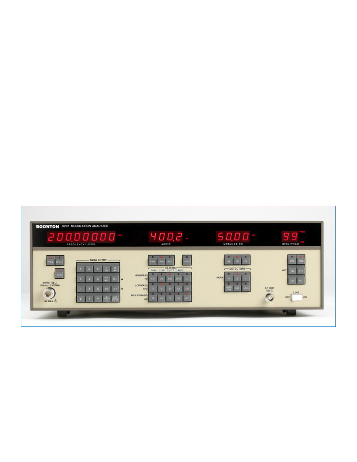
The 8201 instrument displays are shown as below in Figure-1. The
front panel of the Model 8201 is organized for simple instrument
operation. It consists of a display window and a separate keyboard
area. The display area contains the carrier FREQUENCYLEVEL display,
the AUDIO display, the MODULATION display, and the SPCL/PRGM
display. The keys are organized as function keys, data keypad, and
measurement control keys.
The controls, indicators and connectors used during the operation of
the instrument are listed in Table-1 , Table-2 and shown in Figure-2
and Figure-3.
The following instructions walk through a basic operation and func-
tionality tests to verify that the unit is working properly.
1. Turn ON the instrument and press LCL (INIT) key.
2. After a while, the FREQUENCY/LEVEL display will show up with
8201 firmware reference number and the other displays will
contain dashes for about 3 seconds.
3. The message “UNLOC” will then appear in the display window.
4. The audio and modulation displays will contain the [==] mes-
sage
5. The SPCL/PRGM displays will contain 99, the initialization
program number (Please refer to Table 3-8 of the instruction
manual for the meaning of any reported errors).
Figure-1: 8201 Modulation Analyzer Displays
5
Page 6

1 17 18 19 22 4 20 21 5 236 7 2 13 14 15 16 3
30 8 9 10 11 12 25 26 27 28 31 29 32 24
Figure-2: Front View of 8201 Modulation Analyzer
Table-1: Controls, Displays and Connectors of Front Panel of 8201 Modulation Analyzer (Fig-2)
Control, Indicator Or Connector Index Number Function
FREQUENCY/LEVEL display 1 Displays carrier frequency in kHz or MHz, and RF level in dBm or mV. Alternately
displays error codes and messages. The display is eight characters wide and
displays the measurements of carrier level and frequency. In ratio mode the fre-
quency can be displayed in % or delta frequency and the level in % or dB.
AUDIO display 2 AUDIO display is four characters wide and it displays modulation frequency in Hz
or kHz and distortion in % or dB SINAD. In ratio mode distortion and SINAD can
be displayed in % or dB and the audio frequency can be displayed in % or delta
frequency.
MODULATION display 3 The MODULATION display is four characters wide and it displays modulation in %
for AM, kHz for FM deviation, and RAD for PM deviation. Also displays ratio in %
or dB.
BUS Status display 4 Displays current IEEE-488 bus status; REM (remote enabled), LSN (listener ad-
dressed), TLK (talker addressed), and SRQ (service request active).
SPCL/PRGM display 5 The SPCL/PRGM display is an entry only display which is two characters wide and
display the current program number or selected special function. Units are PRGM
for program number, SPCL for special function, and ADRS for IEEE-488 bus ad-
dress. Also included a LINE annunciator which indicates that ac power is applied.
FREQ key 6 Selects carrier frequency as the active function. Use before setting carrier fre-
quency or to activate carrier frequency display.
LEVEL key 7 Selects carrier level as the active function. Use before setting carrier level or to
activate the level display.
AUTO key 8 Forces the selected function to the measurement mode. Not active for the PRGM
and SPCL functions.
6
Page 7

Control, Indicator Or Connector Index Number Function
DATA ENTRY keys:
0 – 9 keys
. key
- key
V/GHz key
mV/MHz key
kHz key
%Hz key
dBm key
DEL(↑) key
CLR(↓) key
RAD/ENTER
High-pass Hz keys:
<10/THRU
30/CCIR
300/CCITT
9
Number entry keys.
Select decimal point during data entry.
Prefix for negative quantity.
Selects volts or gigahertz units.
Selects millivolts or megahertz units.
Selects kilohertz units.
Selects percent or Hertz units.
Selects decibels referenced to 1 milliwatt.
Deletes the last entered digit, or increments parameter.
Clears errors or current data entry, or decrements parameter.
Selects radians or unitless number termination.
10
Selects the < 10 Hz high-pass or THRU bandpass filter.
Selects the 30 Hz high-pass or CCIR bandpass filter.
Selects the 300 Hz high-pass or CCIIT bandpass filter.
3000/C-MSG
ALT
Low-pass Hz keys:
11
3
15
20
50
220
De-emphasis uS keys:
12
25
50
75
750
OFF
SINAD key 13 Selects SINAD audio distortion measurement.
FREQ (audio) 14 Selects audio frequency as the active function.
Selects the 3000 Hz high-pass or C-MSG bandpass filter.
Toggles filter selection from high-pass to bandpass.
Selects the 3 kHz low-pass filter.
Selects the 15 kHz low-pass filter.
Selects the 20 kHz low-pass filter.
Selects the 50 kHz low-pass filter.
Selects the 220 kHz low-pass filter.
Selects the 25 us de-emphasis filter.
Selects the 50 us de-emphasis filter.
Selects the 75 us de-emphasis filter.
Selects the 750 us de-emphasis filter.
Deselects the de-emphasis filters.
Use before setting audio frequency for SINAD measurements, or to activate the
audio frequency display.
7
Page 8

Control, Indicator Or Connector Index Number Function
DIST key 15 Selects audio distortion measurement.
RATIO key 16 Alternate action key. Changes the active display from absolute to relative. Units
keys may be used to select displayed units.
AM key 17 Selects AM modulation as the active function.
Use before setting AM modulation reference for subsequent ratio measurement,
or to activate the AM modulation display.
FM key 18 Selects FM modulation as the active function.
Use before setting FM modulation reference for subsequent ratio measurement, or
to activate the FM modulation display.
PM key 19 Selects PM modulation as the active function.
Use before setting PM modulation reference for subsequent ratio measurement, or
to activate the PM modulation display.
SPCL key 20 Selects special function as the active function.
Use before selecting special function.
PRGM key 21 Selects instrument program as the active function.
Use before selecting program number for store or recall.
LCL/INIT key 22 Causes instrument to “go-to-Iocal” if local lockout is not active and remote is ac-
tive, or initialize when the instrument is in the local state.
STO key 23 Stores the instrument setup at selected program number.
RCL key 24 Recalls instrument setup from selected program number.
PEAK keys:
+key
-key
±key
QUASI-PEAK key 26 Selects CCIR 386-3 peak detector for display. The display is peak responding,
RMS key 27 Selects a true RMS detector for modulation display.
HOLD key 28 Alternate action key used to display the greater of the current or last modulation
CAL key 29 Causes the selected function to be calibrated. Active for carrier LEVEL, AM, FM, and
25
Selects + peak detector for display.
Selects - peak detector for display.
Selects peak average modulation display. The display is ( + peak ( + ) -peak )/2.
calibrated in RMS.
reading.
PM.
RF IN connector 30 RF input connector, used to apply an external carrier signal.
AF OUT connector 31 Audio output connector, used to connect the demodulated signal to external test
equipment.
LINE switch 31 Switches the instrument ac power supply ON or OFF.
8
Page 9

2 3 1 4 10 5 6 11 7
Figure-3: Rear View of 8201 Modulation Analyzer
Table-2: Controls, Displays and Connectors of Back Panel of 8201 Modulation Analyzer (Figure-3)
12 8 13 9
Control, Indicator or Connector Index Number Function
Fuse holder 1 Holds fuse for ac line protection.
Line connector 2 Permits connection of instrument to ac power supply.
Voltage Selector Switch 3 Permits the selection of various ac power supply voltages.
IEEE-488 bus connector 4 Provides a means for connecting the Model 8201 to a system control bus.
IF out connector 5 Provides a means for connecting the intermediate frequency signal to external
test equipment.
FM out connector 6 Provides a means for connecting the demodulated FM signal to external test
equipment.
AM out connector 7 Provides a means for connecting the demodulated AM signal to external test
equipment.
DIST out connector 8 Provides a means for connecting the distortion analyzer signal output to external
test equipment.
EXT REF connector 9 Provides a means for connecting an external 10 MHz frequency standard to the
internal time base circuits.
Optional:
CAL OUT connector
10 Provides a means for connecting the optional 50 MHz,
0 dBm calibrator to the Model 8201 for level calibration.
RF IN connector 11 Optional RF input connector, used to apply an external carrier signal.
AUDIO OUT connector 12 Provides a means for connecting the modulation signal to external filters or pro-
cessing circuits.
AUDIO IN connector 13 Provides a means for connecting an external audio signal to the internal baseband
processing circuits.
9
Page 10
Getting familiar with Function Keys
Getting familiar with Data Keypad
The function keys of 8201 modulation analyzer are described as
below:
The top row of illuminated switches are the function keys. These
keys are used to select the parameter to be displayed and to enable
the data keypad for subsequent data entry. The functions are carrier
FREQ, carrier LEVEL, audio SINAD, audio FREQ, audio DIST, AM, FM, PM,
SPCL, and PRGM. The LED in the switch of the selected function will
be illuminated continuously; the others will be off unless a measure-
ment of that function is in progress. In this case the LED will flash
during the measurement interval.
FREQ function key
To select a function press the desired function key. The units legends
associated with that function will appear immediately to the right of
the numeric display.
For example, select the carrier FREQ function and press the 1 and V/
GHZ keys. The display will now contain the number 1000.0000 and
the active legend will be MHz
FM function key
Depress the FM function key. The LED in the carrier FREQ key will go
out, and the LED is the FM key will illuminate. Depress the 1, 0, and
kHz keys. The number 10.00 will now be displayed in the modulation
display.
All other function keys operate in the same manner, except that data
cannot be entered when the DIST or SINAD functions are selected.
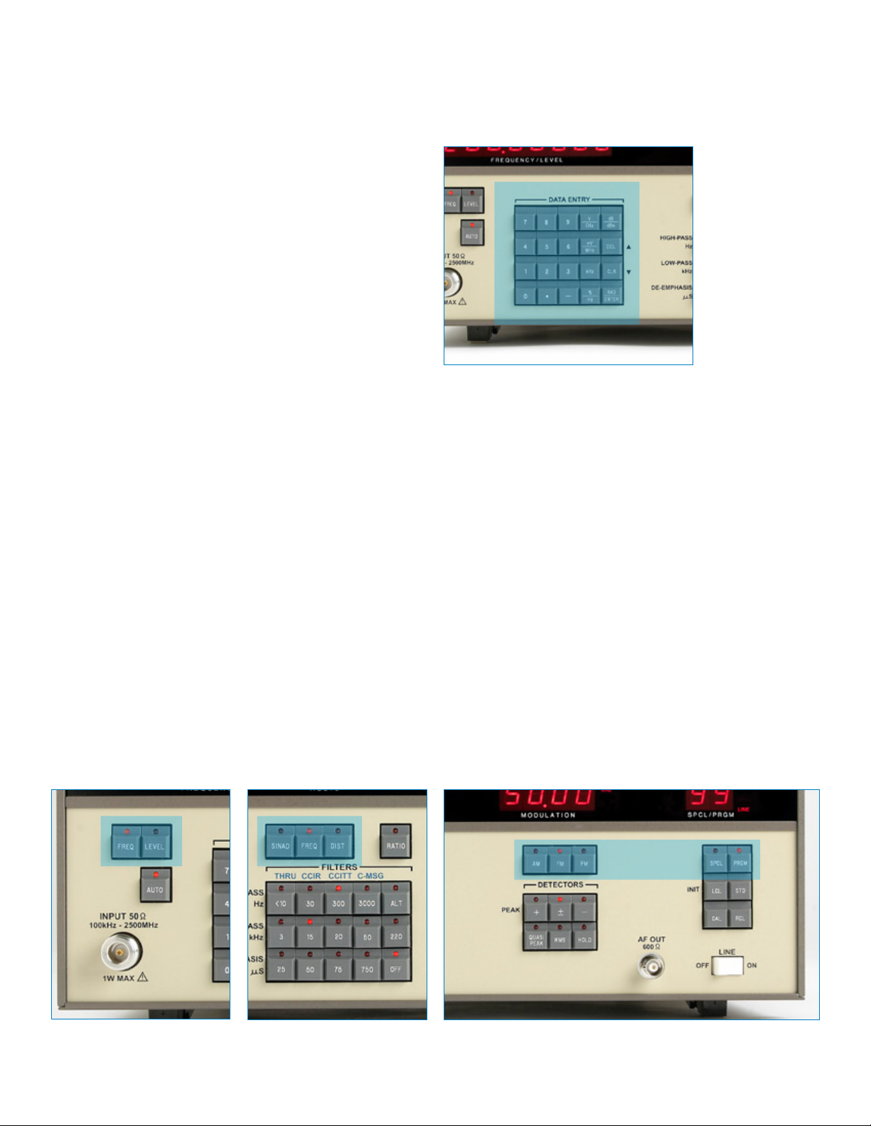
Operation of the data keypad is conventional. The data keypads of
the 8201 Modulation Analyzer are described as below:
Figure-5: Data Keypad of 8201 Modulation Analyzer
MHz key
Select the carrier FREQ function and depress the [8] key. The carrier
frequency display will indicate ‘8 and the unit’s legend will go out.
The tick mark (‘) indicates that the number displayed has not yet
been entered.
Continue by depressing the [2], [.], [1] and [5] keys and the MHz
key to enter the number. The display will now indicate 82.15000
MHz. (Note: It is not necessary to enter any trailing zeroes, nor is it
necessary to depress the ENTER key if a units key is used. While this
is the most efficient way to enter 82.15 MHz, it is equally valid to
enter 82150 kHz, 82150000 Hz, etc).
DEL and CLR Key
If at any time before entry the wrong digit is entered, depress the
DEL key to clear the digit, or depress the CLR key to clear all input and
restore the previous frequency display.
Figure-4: Function Keys of 8201 Modulation Analyzer
10
Page 11

kHz and GHz Keys
The kHz and GHz keys are provided for convenience when entering
frequency; however, the display will only indicate in MHz. Similarly,
the V key can be used for entering input level; however, the display
will indicate in millivolts.
ENTER key
The ENTER key is used for unitless quantities, such as special function
and program numbers.
CLR key
The CLR key is used to recover from errors. Without changing func-
tion, depress the dBm key. The FREQUENCY/LEVEL display will now
indicate Error 9 or 11. This means that an inconsistent units key has
been depressed to terminate a data entry.
Depress the CLR key. The display will return to normal. A list of error
codes is presented in Table 3-8, at the end of the section 3-26 of the
8201 instruction manual.
LEVEL Function key
Depress the carrier LEVEL function key, then the 0 and dBm keys. The
FREQUENCY/LEVEL display will now indicate 0.00 dBm.
mV/MHz key
Depress the mV/MHz key. The display will change to 223.6 m V.
Carrier level may be entered in millivolts, volts, or dBm. The control
program will recalculate or rescale numbers as required.
The DEL and CLR keys are also labeled as up- and down-arrow keys
for scrolling through SPCL function menus.
Getting familiar with Measurement
Figure-6: Measurement Control Keys of 8201 Modulation Analyzer
HIGH-PASS Filter keys
Depressing any high-pass switch will cause the selected filter to be
placed into the measurement channel and cancel any other selected
high-pass filter.
LOW-PASS Filter keys
Similarly, depressing any low-pass filter will cause the selected filter
to be placed into the measurement channel and cancel any other
selected low-pass filter.
The maximum low-pass bandwidth selection is a function of carrier
frequency. The control program will automatically adjust the low-
pass filter cutoff frequency as required. The carrier breakpoints and
low-pass filters are:
Carrier Filter
< 500 kHz 15 kHz max
< 10 MHz 50 kHz max
> 10 MHz 220 kHz max
DE-EMPHASIS Filter Keys
The de-emphasis filters are normally available when measuring FM
only. They are selected in the same manner as the high-pass and
low-pass filters, but are automatically removed from the measure-
ment channel when AM or PM modulation function is selected. The
selected de-emphasis filter will be restored when the FM function is
again selected.
Control Keys
The measurement control keys consist of the groups of switches
marked FILTERS and DETECTORS. These keys may be operated at any
time and will affect the MODULATION and AUDIO displays. The filter
switches are arranged as self-cancelling groups of four and five keys.
Depressing any high-pass switch will cause the selected filter to be
placed into the measurement channel and cancel any other selected
high-pass filter. Similarly, depressing any low-pass filter will cause
the selected filter to be placed into the measurement channel and
cancel any other selected low-pass filter.
Additionally, the de-emphasis filters may be placed before or after
the modulation display. This is accomplished by selecting SPCL func-
tion 7 for pre-display and SPCL function 8 for post-display de-em-
phasis. SPCL function 9 permits the de-emphasis filters to be selected
in the AM measurement function. This is useful for performance
verification of the filter 3 dB points.
11
Page 12

OPTIONAL Filter Keys
The ALT key is active if optional filters are installed in the Model
8201. Optional filters available are:
THRU Permits connection of external filters in the audio path
CCIR CCIR recommendation 468-3 bandpass filter
CCITT CCITT recommendation P.53 bandpass filter
C-MSG Bell System Technical Reference 41009 bandpass filter
Other Keys
Any or all of these filters can be installed at one time; however, the
A15 option board is required with any of the filters. The ALT key will
activate the filters marked above the corresponding high-pass key, if
the filters are installed. Error 19 will be displayed if an optional filter
is not installed and the key is depressed.
DETECTOR Switches
The second group of measurement control keys is the DETECTOR
switches. The peak detectors are normally used to measure modula-
tion, however, precision RMS detectors are included in the Model
8201. These detectors are used primarily to characterize noise
residuals and complex or distorted modulation signals. Two detectors
are provided.
RMS Key
The normal function of the RMS key is to select an rms calibrated
display; however, SPCL function 18 can be executed to change the
RMS key to select rms detection calibrated in peak for sinusoidal
modulation. This is particularly useful when comparing peak and RMS
indications of noisy signals.
Figure-7: Other Keys of 8201 Modulation Analyzer
RATIO Key
The RATIO key is an alternate action key which changes the active
display from absolute to relative. In addition, the ratio measure-
ment can be made relative to the current display, or to a set value.
Ratio can be displayed in percent, measurement units, or dB by using
the %, units, and dB keys in the data keypad. For relative frequency
measurements use the % key or for delta frequency use kHz, MHz or
GHz keys.
AUTO key
The AUTO key is used to resume automatic operation of a particular
function. It is active for the carrier FREQ, carrier LEVEL, audio FREQ,
AM, FM, and PM functions. When numerical data is entered into a
particular function window, the LED in the AUTO key will go out. This
indicates that the selected function is not displaying a measured
value. To resume measurement, depress the AUTO key. If carrier FREQ
is the active function, depressing the AUTO key will always force the
Model 8201 to reacquire the carrier signal.
QUASI-PEAK Key
A quasi-peak detector, compatible with CCIR 368-3, is available for
use with the CCIR filter option. This detector is always available,
whether the optional filter is installed or not.
PEAK Keys
The Peak +, -, and ± keys, the RMS key, and the QUASI-PEAK key are
arranged such that only one detector can be selected at a time.
HOLD Key
The HOLD key is used to activate the hold detector mode. It is an al-
ternate action key which can be used with any detector. In operation,
as modulation measurements are made, the larger of the current
measurement or the previous measurement becomes the displayed
modulation. Depress the HOLD key to activate this mode, and then
depress the key again to cancel.
LCL(INIT) key
The LCL(INIT) key is a dual function key. If the Model 8201 is in the
local IEEE•488 bus state and the key is depressed an initialization
restart occurs. This is similar to a power on reset except that the
current instrument status is lost. This does not include bus address
or end-of-string selection. If the Model 8201 is remote enabled, and
the local lockout bus state is not active, the instrument will return to
front panel control.
STO and RCL Keys
The STO and RCL keys are used with the PRGM function key to store
and recall one of the 100 possible instrument control settings.
CAL key
The CAL key is used to calibrate the active function. It is active for
carrier LEVEL, AM, FM, and PM modulation.
12
Page 13

Displayed Messages
UNLOC message
When the Model 8201 unlocks, the FREQUENCY/LEVEL display will be
overwritten with the ‘UNLOC’ message and the AUDIO and MODU-
LATION displays will be overwritten with the [= = ] symbol, which
means display out of range. When a valid carrier is acquired, the
displays will return to normal.
‘IFHI’ and ‘IFLO’ messages
The ‘IFHI’ and ‘IFLO’ messages appear in the modulation display and
indicate that the intermediate frequency level is not within range to
make an accurate measurement. SPCL functions 13 and 14 allow the
operation of these messages to be modified.
‘-CAL-’ Message
When the CAL key is depressed, or during the execution of SPCL
function 30, the message ‘-CAL-’ is written to the FREQUENCY/LEVEL
display to indicate that a calibration sequence is in progress.
‘Error’ message
A normal error response is for the word ‘Error’ to appear in the FRE-
QUENCY/LEVEL display followed by a number indicating the nature of
the error. Error codes are tabulated in Table 3-8 of the 8201 instruc-
tion manual along with a description of the error.
‘SELFCHK’ message
The message ‘SELFCHK’, followed by a changing digit, appears in the
FREQUENCY/LEVEL display at power on, and indicates that a hard-
ware check is in progress. Any error messages displayed indicate a
hardware problem. See Table 3-8 of the 8201 instruction manual for
the meaning of any reported errors.
Other displayed messages are described in detail in the pertinent
operation section.
SPCL 1-4 (MODULATION RANGE SETTINGS)
SPCL functions 1 through 4 permit the operator to select the modula-
tion display range. This is useful for speeding up measurements
where modulation may be removed temporarily, or in situations
where the modulation range is known. This feature is also useful
when decreased display resolution is desired. SPCL 1 is the default
function which is auto range. The others are:
SPCL2 5.000 full-scale
SPCL3 50.00 full-scale
SPCL4 500.0 full-scale
SPCL 5 (ENABLE SLOW PEAK DETECTOR MODE)
SPCL function 5 is provided to slow the response of the peak detec-
tors for modulation signal frequencies below 200 Hz. The detec-
tors are optimized for signal frequencies greater than 200 Hz for
maximum measurement speed. Below 200 Hz additional filtering is
required.
SPCL 6 (DISABLE SLOW DETECTOR MODE)
SPCL function 6 allows the operator to cancel SPCL 5. This is the
default setting.
SPCL 7 (SET PRE-DISPLAY DE-EMPHASIS)
SPCL function 7 allows the operator to change the de-emphasis
filter location from post -display to pre-display. This means that the
de-emphasis filters will affect the displayed modulation readings as
well as the AF OUT signal. This is useful for comparison of receiver de-
emphasis networks to the precision network used in the Model 8201.
SPCL 8 (SET POST-DISPLAY DE-EMPHASIS)
SPCL function 8 allows the operator to change the de-emphasis filter
location from pre-display to post -display. This means that the de-
emphasis filters will not affect the displayed modulation readings,
but will affect the AF OUT signal. This is the default setting for the
de-emphasis filters.
Special Functions
Several of the Model 8201 operating features are internally pro-
grammable by selecting a SPCL function. These functions allow the
operator to change measurement configuration, as well as change
the hardware state of the instrument. Some of the more useful
SPCL functions are listed, the others are included in Table 3-2 of the
instruction manual.
SPCL 0 (CLEAR ALL SPECIALS)
SPCL function 0 allows the operator to reset any active SPCL func-
tions. The instrument special status is returned to the defaults
indicated in Table 3-2 of the instruction manual.
SPCL 11 and 12 are related to setting dB resolution for ratio mea-
surements.
SPCL 15, 16 and 17 are related to IEEE-488 which is described in
details on the Table 3-2 of the instruction manual.
SPCL 30 (MODULATION DETECTOR CALIBRATION):
SPCL function 30 is the modulation detector calibration program.
When executed the –CAL- message will appear in the FREQUENCY/
LEVEL display and detector calibration will begin. The calibration rou-
tine will take about 80 seconds to complete. The AM detector is cali-
brated first, followed by the rms detector, the FM detector and finally
the PM detector. If calibration error occurs, they will be displayed as
the particular is being calibrated.
13
Page 14

Calibration and Performance Tests
The internal calibrators of the 8201 Modulation Analyzer provide
modulation standards for AM, FM and PM measurements. They are
activated by the operator as required by the measurement.
Specifications
AM 0.1% accuracy
FM 0.1% accuracy
PM 1.0% accuracy
FM Calibration
The calibration process consists of:
1. Applying to the FM discriminator , in alternation, two accurately
controlled frequencies
2. Measuring the resulting recovered modulation information
3. Computing a correction factor for subsequent FM measure-
ments.
AM Calibration
The operation of the AM calibrator is similar to that of the FM
calibrator.
For detailed theory of operation of the calibration for both AM,
FM and PM, please refer to section 5 “Performance Test 12” of the
instruction manual. The mathematical procedures used to determine
the accuracy of the calibration is disclosed in this section. Since the
calibrators are so precise, measurement verification of the stated
accuracy is not practical.
Wireless Telecom Group Inc.
25 Eastmans Rd
Parsippany, NJ
United States
Tel: +1 973 386 9696
Fax: +1 973 386 9191
www.boonton.com
© Copyright 2010
All rights reserved.
B/8201QS/1110/EN
Note: Specifications, terms and conditions
are subject to change without prior notice.
 Loading...