

Boonton 4540 Peak Power Meter User Manual

INSTRUCTION MANUAL
4540 SERIES
RF POWER METER
This manual covers instrument REV DATE 10/04/2012
serial #s: 11001 and higher MANUAL P/N 98406100A
CD P/N 98406199A
Wireless Telecom Group
25 EASTMANS ROAD, PARSIPPANY, NJ 07054
Telephone: 973-386-9696
Fax: 973-386-9191
Email: boonton@boonton.com
Web: www.wtcom.com

Boonton 4540 Series RF Power Meter
ii
INSTRUCTION MANUAL, 4540 SERIES RF POWER METER
Revision date 10/04/2012
© Copyright in 2005-2012, by BOONTON Electronics, a subsidiary of the Wireless Telecom
Group, Inc.
Parsippany, NJ, USA. All rights reserved.
P/N 98406100A
This manual covers instrument serial numbers: 11001 and higher.
The 4540 Application software used in this product is licensed by Boonton Electronics, a
subsidiary of the Wireless Telecom Group, Inc.
K-Connector® is a registered trademark of Anritsu Corporation.
Contents

Boonton 4540 Series RF Power Meter
iii
SAFETY SUMMARY
The following general safety precautions must be observed during all phases of operation and maintenance
of this instrument. Failure to comply with these precautions or with specific warnings elsewhere in this
manual violates safety standards of design, manufacture, and intended use of the instrument. Boonton
Electronics assumes no liability for the customer’s failure to comply with these requirements.
THE INSTRUMENT MUST BE GROUNDED
To minimize shock hazard the instrument chassis and cabinet must be connected to an electrical ground.
The instrument is equipped with a NEMA three conductor, three prong power cable. The power cable must
either be plugged into an approved three-contact electrical outlet or used with a three-contact to a twocontact adapter with the (green) grounding wire firmly connected to an electrical ground in the power
outlet.
DO NOT OPERATE THE INSTRUMENT IN AN EXPLOSIVE ATMOSPHERE
Do not operate the instrument in the presence of flammable gases or fumes.
KEEP AWAY FROM LIVE CIRCUITS
Operating personnel must not remove instrument covers. Component replacement and internal adjustments
must be made by qualified maintenance personnel. Do not replace components with the power cable
connected. Under certain conditions dangerous voltages may exist even though the power cable was
removed, therefore; always disconnect power and discharge circuits before touching them.
DO NOT SERVICE OR ADJUST ALONE
Do not attempt internal service or adjustment unless another person, capable or rendering first aid and
resuscitation, is present.
DO NOT SUBSTITUTE PARTS OR MODIFY INSTRUMENT
Do not install substitute parts or perform any unauthorized modifications or the instrument. Return the
instrument to Boonton Electronics for repair to ensure that the safety features are maintained.
LITHIUM BATTERIES
This product contains Lithium batteries that must be disposed of in strict compliance with environmental
regulations in your jurisdiction.
Contents
Boonton 4540 Series RF Power Meter
iv
SAFETY SYMBOLS
This safety requirement symbol (located on the rear panel) has been adopted by the
International Electro-technical Commission, Document 66 (Central Office) 3, Paragraph
5.3, which directs that an instrument be so labeled if, for the correct use of the instrument,
it is necessary to refer to the instruction manual. In this case it is recommended that
reference be made to the instruction manual when connecting the instrument to the proper
power source. Verify that the correct fuse is installed for the power available.
The CAUTION symbol denotes a hazard. It calls attention to an operational procedure,
practice or instruction that, if not followed, could result in damage to or destruction of
part or all of the instrument and accessories. Do not proceed beyond a CAUTION symbol
until its conditions are fully understood and met.
The NOTE symbol is used to mark information which should be read. This information
can be very useful to the operating in dealing with the subject covered in this section.
The HINT symbol is used to identify additional comments which are outside of the
normal format of the manual, however can give the user additional information about the
subject.
Contents

Boonton 4540 Series RF Power Meter
v
1. General Information .............................................................................................. 1-1
1.1 Organization .......................................................................................................... 1-1
1.2 Description ............................................................................................................ 1-2
1.3 Features ................................................................................................................. 1-3
1.4 Accessories ........................................................................................................... 1-5
Standard ............................................................................................................... 1-5
Optional................................................................................................................ 1-5
Sensors ................................................................................................................. 1-5
1.5 Models, Options and Configurations .................................................................... 1-5
1.6 Specifications ........................................................................................................ 1-6
SENSOR INPUTS ............................................................................................... 1-6
MEASUREMENT SYSTEM .............................................................................. 1-6
TIME BASE......................................................................................................... 1-6
TRIGGER ............................................................................................................ 1-7
X-AXIS (Statistical)............................................................................................. 1-7
PULSE MODE OPERATION ............................................................................. 1-8
MODULATED MODE OPERATION ................................................................ 1-8
CALIBRATION SOURCE .................................................................................. 1-9
EXTERNAL INTERFACES ............................................................................... 1-9
PHYSICAL AND ENVIRONMENTAL CHARACTERISTICS ..................... 1-10
OTHER CHARACTERISTICS ......................................................................... 1-10
REGULATORY CHARACTERISTICS ........................................................... 1-10
2. Installation .............................................................................................................. 2-1
2.1 Unpacking & Repacking ....................................................................................... 2-1
2.2 Power Requirements ............................................................................................. 2-2
2.3 Connections .......................................................................................................... 2-2
2.4 Preliminary Check ................................................................................................ 2-3
3. Getting Started ....................................................................................................... 3-1
3.1 Organization .......................................................................................................... 3-1
3.2 Operating Controls, Indicators and Connections .................................................. 3-1
3.3 LCD Monitor Display ........................................................................................... 3-6
3.4 Initialize .............................................................................................................. 3-10
3.5 Calibration .......................................................................................................... 3-14
3.6 Making Measurements ........................................................................................ 3-17
3.6.1 Modulated Mode .......................................................................................... 3-17
3.6.2 Pulse Mode................................................................................................... 3-18
3.6.3 Statistical Mode ........................................................................................... 3-19
Contents

Boonton 4540 Series RF Power Meter
vi
4. Operation ................................................................................................................ 4-1
4.1 Manual Operation ................................................................................................. 4-1
4.2 Control Menus ...................................................................................................... 4-1
4.3 Numerical Data Entry ........................................................................................... 4-2
4.4 Sensor Calibration ................................................................................................. 4-3
4.5 Menu Reference .................................................................................................... 4-4
4.5.1 Main Menu - Pulse and Modulated Modes - Pg 1 (Top Level) ..................... 4-4
4.5.2 Main Menu - Pulse and Modulated Modes - Pg 2 (Top Level) ..................... 4-5
4.5.3 Main Menu - Statistical Mode - Pg 1 (Top Level)......................................... 4-6
4.5.4 Main Menu - Statistical Mode - Pg 2 (Top Level)......................................... 4-7
4.5.5 Measure Menu ............................................................................................... 4-8
4.5.6 Channel Menu .............................................................................................. 4-10
4.5.7 Channel 1 | 2 Menu ..................................................................................... 4-11
4.5.8 Channel > Calibration Menu ........................................................................ 4-13
4.5.9 Channel > Extensions Pg 1 Menu (Modulated Mode) ................................ 4-15
4.5.10 Channel > Extensions Pg 1 > Corrections Menu (Modulated Mode) ........ 4-17
4.5.11 Channel > Extensions Pg 2 Menu (Modulated Mode) .............................. 4-19
4.5.12 Channel > Extensions Pg 2 > Alarms Menu (Modulated Mode) .............. 4-21
4.5.13 Channel > Extensions Pg 1 Menu (Pulse Mode) ....................................... 4-23
4.5.14 Channel > Extensions Pg 1 > Corrections Menu (Pulse Mode) ................ 4-25
4.5.15 Channel > Extensions Pg 1 > Define Pulse Menu (Pulse Mode) .............. 4-27
4.5.16 Channel > Extensions Pg 1 > Define Pulse > Pulse Gate Menu................ 4-29
4.5.17 Channel > Extensions Pg 2 Menu (Pulse Mode) ...................................... 4-30
4.5.18 Channel > Extensions Pg 2 > Alarms Menu (Pulse Mode) ....................... 4-32
4.5.19 Channel > Extensions Pg 1 Menu (Statistical Mode) ................................ 4-34
4.5.20 Channel > Extensions Pg 1 > Corrections Menu (Statistical Mode) ......... 4-35
4.5.21 Channel > Extensions Pg 2 Menu (Statistical Mode) ................................ 4-37
4.5.22 Channel > Extensions Pg 2 > Alarms Menu (Statistical Mode) ................ 4-39
4.5.23 Channel > Ref 1 | 2 Menu .......................................................................... 4-41
4.5.24 Trigger Menu (Pulse Mode)....................................................................... 4-43
4.5.25 Time Menu (Modulated and Pulse Mode) ................................................. 4-45
4.5.26 Stat Mode Menu (Statistical Mode) ........................................................... 4-47
4.5.27 Term Options Menu (Statistical Mode) ..................................................... 4-48
4.5.28 Cursors Menu (Statistical Mode) ............................................................... 4-49
4.5.29 Markers Menu (Modulated and Pulse Modes)........................................... 4-50
4.5.30 Display Menu ............................................................................................. 4-51
4.5.31 Display > Graph Header Menu ................................................................. 4-52
4.5.32 Display > Text Mode Menu ...................................................................... 4-54
4.5.33 Display > Text Mode > Ch1|2 Options Menu .......................................... 4-55
4.5.34 Display > Backlight Menu ........................................................................ 4-57
4.5.35 System Menu ............................................................................................. 4-58
4.5.36 System > I/O Config Menu ....................................................................... 4-59
4.5.37 System > I/O Config > Ethernet Menu ..................................................... 4-60
4.5.38 System > I/O Config > Ethernet > Extensions Menu ............................... 4-61
Contents

Boonton 4540 Series RF Power Meter
vii
4.5.39 System > I/O Config > Multi IO Menu .................................................... 4-63
4.5.40 System > I/O Config > Multi IO > IO Mode Status Out Menu ................ 4-64
4.5.41 System > I/O Config > Multi IO > IO Mode Rec Out Menu ................... 4-65
4.5.42 System > I/O Config > Multi IO > Rec Out > Rec Limits Menu ............. 4-66
4.5.43 System > I/O Config > Multi IO > IO Mode Trig Out Menu ................... 4-67
4.5.44 System > I/O Config > Multi IO > IO Mode Volt Out Menu .................. 4-68
4.5.45 System > Calibrator Menu (Internal 50 MHz) .......................................... 4-69
4.5.46 System > Calibrator Menu (External 1 GHz - optional) ........................... 4-70
4.5.47 System > Calibrator > Pulse - Preset Menu (Ext 1 GHz - opt.) ................ 4-72
4.5.48 System > Calibrator > Pulse - Variable Menu (Ext 1 GHz - opt.) ............. 4-73
4.5.49 System > Reports Menu ............................................................................ 4-75
4.5.50 System > Servicing Menu ......................................................................... 4-78
4.5.51 System > Servicing > Security Menu ....................................................... 4-79
4.5.52 System > Sensor Data Menu ..................................................................... 4-81
4.5.53 Setup Menu ................................................................................................ 4-83
4.5.54 Setup > Preset Menu ................................................................................. 4-84
4.5.55 Setup > User Presets Menu ....................................................................... 4-85
4.6 Cal/Zero Key Menu ............................................................................................ 4-86
5. Remote Operation .................................................................................................. 5-1
5.1 GPIB Configuration .............................................................................................. 5-1
5.2 LAN Configuration ............................................................................................... 5-1
5.3 USB Configuration ............................................................................................... 5-1
5.4 SCPI Language ..................................................................................................... 5-2
5.4.1 SCPI Structure ............................................................................................... 5-2
5.4.2 Long and Short Form Keywords.................................................................... 5-2
5.4.3 Subsystem Numeric Suffixes ......................................................................... 5-2
5.4.4 Colon Keyword Separators ............................................................................ 5-2
5.4.5 Command Arguments and Queries ................................................................ 5-3
5.4.6 Semicolon Command Separators ................................................................... 5-3
5.4.7 Command Terminators .................................................................................. 5-3
5.4.8 4540 Series SCPI Implementation ................................................................. 5-3
5.5 Basic Measurement Information ........................................................................... 5-5
5.5.1 Service Request .............................................................................................. 5-5
5.6 SCPI Command Reference ................................................................................... 5-6
5.6.1 IEEE 488.2 Commands .................................................................................. 5-6
*CLS .................................................................................................................... 5-6
*ESE .................................................................................................................... 5-6
*ESR? .................................................................................................................. 5-7
*IDN? ................................................................................................................... 5-7
*OPC .................................................................................................................... 5-7
*OPC? .................................................................................................................. 5-8
*OPT? .................................................................................................................. 5-8
*RST .................................................................................................................... 5-8
Contents

Boonton 4540 Series RF Power Meter
viii
*SRE .................................................................................................................... 5-8
*STB? .................................................................................................................. 5-9
*TRG.................................................................................................................... 5-9
*TST? ................................................................................................................... 5-9
*WAI.................................................................................................................. 5-10
5.6.2 CALCulate Subsystem ................................................................................. 5-11
CALCulate:LIMit:CLEar[:IMMediate] ............................................................. 5-11
CALCulate:LIMit:FAIL? ................................................................................... 5-11
CALCulate:LIMit:LOWer[:POWer] ................................................................. 5-11
CALCulate:LIMit:UPPer[:POWer] ................................................................... 5-12
CALCulate:LIMit:LOWer:STATe .................................................................... 5-12
CALCulate:LIMit:UPPer:STATe ...................................................................... 5-12
CALCulate:LIMit[:BOTH]:STATe ................................................................... 5-12
CALCulate:MATH ............................................................................................ 5-13
CALCulate:MODE ............................................................................................ 5-13
CALCulate:PKHLD ........................................................................................... 5-13
CALCulate:REFerence:COLLect ...................................................................... 5-14
CALCulate:REFerence:DATA .......................................................................... 5-14
CALCulate:REFerence:STATe ......................................................................... 5-14
CALCulate:STATe ............................................................................................ 5-15
CALCulate:UNITs ............................................................................................. 5-15
5.6.3 CALibration Subsystem ............................................................................... 5-16
CALibration:EXTernal:AUTOcal ..................................................................... 5-16
CALibration:EXTernal:FIXedcal ...................................................................... 5-16
CALibration:EXTernal:ZERO ........................................................................... 5-16
CALibration[:INTernal]:AUTOcal .................................................................... 5-17
CALibration[:INTernal]:FIXedcal ..................................................................... 5-17
CALibration[:INTernal]:ZERO ......................................................................... 5-17
5.6.4 DISPlay Subsystem ...................................................................................... 5-18
DISPlay:BACKlight:BRIGhtness ...................................................................... 5-18
DISPlay:CLEar .................................................................................................. 5-18
DISPlay:ENVELOPE ........................................................................................ 5-18
DISPlay:MODE ................................................................................................. 5-18
DISPlay:MODUlated:TIMEBASE .................................................................... 5-19
DISPlay:MODUlated:TSPAN ........................................................................... 5-19
DISPlay:PULSe:TIMEBASE ............................................................................ 5-19
DISPlay:PULSe:TSPAN.................................................................................... 5-20
DISPlay:SCREensaver:BRIGhtness .................................................................. 5-20
DISPlay:SCREensaver:STATe .......................................................................... 5-20
DISPlay:SCREensaver:TIMe ............................................................................ 5-20
DISPlay:[TEXt:]LIN:RESolution ...................................................................... 5-21
DISPlay:[TEXt:]LOG:RESolution .................................................................... 5-21
DISPlay:TRACe:HOFFSet ................................................................................ 5-21
DISPlay:TRACe:HSCALe ................................................................................ 5-21
DISPlay:TRACe:VCENTer ............................................................................... 5-22
DISPlay:TRACe:VSCALe ................................................................................ 5-22
Contents

Boonton 4540 Series RF Power Meter
ix
5.6.5 FETCh Queries ............................................................................................ 5-23
FETCh:ARRay:AMEAsure:POWer? ................................................................ 5-23
FETCh:ARRay:AMEAsure:STATistical? ......................................................... 5-23
FETCh:ARRay:AMEAsure:TIMe? ................................................................... 5-24
FETCh:ARRay:CW:POWer? ............................................................................ 5-24
FETCh:ARRay:MARKer:POWer?.................................................................... 5-25
FETCh:ARRay:TEMPerature:AVERage? ........................................................ 5-25
FETCh:ARRay:TEMPerature:CURRent? ......................................................... 5-25
FETCh:CW:POWer? ......................................................................................... 5-25
FETCh:INTERval:AVERage? ........................................................................... 5-26
FETCh:INTERval:MAXFilt? ............................................................................ 5-26
FETCh:INTERval:MINFilt? .............................................................................. 5-26
FETCh:INTERval:MAXimum? ........................................................................ 5-26
FETCh:INTERval:MINimum? .......................................................................... 5-27
FETCh:INTERval:PKAVG? ............................................................................. 5-27
FETCh:KEY? ..................................................................................................... 5-27
FETCh:MARKer:AVERage? ............................................................................ 5-27
FETCh:MARKer:CURsor:PERcent? ................................................................ 5-28
FETCh:MARKer:CURsor:POWer? .................................................................. 5-28
FETCh:MARKer:DELTa? ................................................................................. 5-28
FETCh:MARKer:MAXimum? .......................................................................... 5-28
FETCh:MARKer:MINimum?............................................................................ 5-29
FETCh:MARKer:RATio?.................................................................................. 5-29
FETCh:MARKer:RDELTa? .............................................................................. 5-29
FETCh:MARKer:RRATio? ............................................................................... 5-29
FETCh:TEMPerature:AVERage?...................................................................... 5-30
FETCh:TEMPerature:CURRent? ...................................................................... 5-30
FETCh:TEMPerature:INTernal? ....................................................................... 5-30
5.6.6 INITiate and ABORt Commands................................................................. 5-31
ABORt ............................................................................................................... 5-31
INITiate:CONTinuous ....................................................................................... 5-31
INITiate[:IMMediate[:ALL]] ............................................................................ 5-31
5.6.7 MARKer Subsystem .................................................................................... 5-32
MARKer:POSItion:PERcent ............................................................................. 5-32
MARKer:POSItion:POWer ............................................................................... 5-32
MARKer:POSItion:PIXel .................................................................................. 5-32
MARKer:POSItion:TIMe .................................................................................. 5-33
5.6.8 MEASure Queries ........................................................................................ 5-34
MEASure:POWer? ............................................................................................ 5-34
MEASure:VOLTage? ........................................................................................ 5-34
5.6.9 MEMory Subsystem .................................................................................... 5-35
MEMory:SNSR:CFFAST? ................................................................................ 5-35
MEMory:SNSR:CFSLOW? .............................................................................. 5-35
MEMory:SNSR:CWRG? ................................................................................... 5-35
MEMory:SNSR:CWSH? ................................................................................... 5-35
MEMory:SNSR:INFO? ..................................................................................... 5-36
Contents

Boonton 4540 Series RF Power Meter
x
MEMory:SNSR:LFLIN? ................................................................................... 5-36
MEMory:SNSR:MESSage? ............................................................................... 5-36
MEMory:SNSR:TEMPCOMP? ......................................................................... 5-36
MEMory:SYS:LOAD ........................................................................................ 5-37
MEMory:SYS:STORe ....................................................................................... 5-37
5.6.10 OUTPut Subsystem .................................................................................... 5-38
OUTPut:EXTernal:LEVel[:POWer] .................................................................. 5-38
OUTPut:EXTernal:POLArity ............................................................................ 5-38
OUTPut:EXTernal:PRESent? ............................................................................ 5-39
OUTPut:EXTernal:PULSe:CTRL ..................................................................... 5-39
OUTPut:EXTernal:PULSe:DCYCle ................................................................. 5-39
OUTPut:EXTernal:PULse:PERiod.................................................................... 5-39
OUTPut:EXTernal:PULse:PERWID ................................................................. 5-40
OUTPut:EXTernal:PULse:SOURce .................................................................. 5-40
OUTPut:EXTernal:SIGNal ................................................................................ 5-40
OUTPut:INTernal:LEVel[:POWer] ................................................................... 5-40
OUTPut:INTernal:SIGNal ................................................................................. 5-41
OUTPut:MIO:MODe ......................................................................................... 5-41
OUTPut:[MIO:]RECOroder:FORCe ................................................................. 5-41
OUTPut:[MIO:]RECOroder:MAX .................................................................... 5-41
OUTPut:[MIO:]RECOroderMIN ...................................................................... 5-42
OUTPut:[MIO:]RECOroder:POLarity .............................................................. 5-42
OUTPut:[MIO:]RECOroder:SCALing .............................................................. 5-42
OUTPut:[MIO:]RECOroder:SOURce ............................................................... 5-42
OUTPut:MIO:STATus:SETTing ....................................................................... 5-43
OUTPut:MIO:STATus:SOURce ....................................................................... 5-43
OUTPut:MIO:TRIGout:SOURce ...................................................................... 5-44
OUTPut:MIO:VOLTage .................................................................................... 5-44
5.6.11 READ Queries ........................................................................................... 5-45
READ:ARRay:AMEAsure:POWer? ................................................................. 5-45
READ:ARRay:AMEAsure:STATistical?.......................................................... 5-45
READ:ARRay:AMEAsure:TIMe? .................................................................... 5-46
READ:ARRay:CW:POWer? ............................................................................. 5-46
READ:ARRay:MARKer:POWer? .................................................................... 5-47
READ:CW:POWer? .......................................................................................... 5-47
READ:INTERval:AVERage?............................................................................ 5-47
READ:INTERval:MAXFilt? ............................................................................. 5-47
READ:INTERval:MINFilt? ............................................................................... 5-48
READ:INTERval:MAXimum? ......................................................................... 5-48
READ:INTERval:MINimum? ........................................................................... 5-48
READ:INTERval:PKAVG? .............................................................................. 5-48
READ:MARKer:AVERage? ............................................................................. 5-49
READ:MARKer:DELTa? .................................................................................. 5-49
READ:MARKer:MAXimum? ........................................................................... 5-49
READ:MARKer:MINimum? ............................................................................ 5-49
READ:MARKer:CURsor:PERcent? ................................................................. 5-50
Contents

Boonton 4540 Series RF Power Meter
xi
READ:MARKer:CURsor:POWer? ................................................................... 5-50
READ:MARKer:RATio? .................................................................................. 5-50
READ:MARKer:RDELTa? ............................................................................... 5-51
READ:MARKer:RRATio? ................................................................................ 5-51
5.6.12 SENSe Subsystem ...................................................................................... 5-52
SENSe:AVERage .............................................................................................. 5-52
SENSe:BANDwidth .......................................................................................... 5-52
SENSe:ARRay:CALTemp? ............................................................................... 5-53
SENSe:CALTemp? ............................................................................................ 5-53
SENSe:CORRection:CALFactor ....................................................................... 5-53
SENSe:CORRection:DCYCle ........................................................................... 5-53
SENSe:CORRection:FREQuency ..................................................................... 5-54
SENSe:CORRection:OFFSet ............................................................................. 5-54
SENSe:CORRection:TEMPcomp...................................................................... 5-54
SENSe:FILTer:STATe ...................................................................................... 5-55
SENSe:FILTer:TIMe ......................................................................................... 5-55
SENSe:IMPedance ............................................................................................. 5-55
SENSe:PULSe:DISTal ...................................................................................... 5-55
SENSe:PULSe:ENDGT ..................................................................................... 5-56
SENSe:PULSe:MESIal ...................................................................................... 5-56
SENSe:PULSe:PROXimal ................................................................................ 5-56
SENSe:PULSe:STARTGT ................................................................................ 5-57
SENSe:PULSe:UNIT ......................................................................................... 5-57
SENSe:SENSOR:TYPE? ................................................................................... 5-57
5.6.13 SENSe:MBUF Data Array Commands ..................................................... 5-58
SENSe:MBUF:SIZe ........................................................................................... 5-59
SENSe:MBUF:RATe ......................................................................................... 5-59
SENSe:MBUF:POSition .................................................................................... 5-60
SENSe:MBUF:COUNt ...................................................................................... 5-60
SENSe:MBUF:INDEX ...................................................................................... 5-60
SENSe:MBUF:MEASurement .......................................................................... 5-61
SENSe:MBUF:DATA ....................................................................................... 5-61
5.6.14 STATus Commands ................................................................................... 5-62
STATus:DEVice:CONDition? .......................................................................... 5-62
STATus:DEVice:ENABle ................................................................................. 5-62
STATus:DEVice:EVENt? ................................................................................. 5-63
STATus:DEVice:NTRansition .......................................................................... 5-63
STATus:DEVice:PTRansition ........................................................................... 5-63
STATus:OPERation:CONDition? ..................................................................... 5-64
STATus:OPERation:ENABle ............................................................................ 5-64
STATus:OPERation:EVENt? ............................................................................ 5-64
STATus:OPERation:NTRansition ..................................................................... 5-65
STATus:OPERation:PTRansition...................................................................... 5-65
STATus:PRESet ................................................................................................ 5-65
STATus:QUEStionable:CONDition? ................................................................ 5-66
STATus:QUEStionable:ENABle ....................................................................... 5-66
Contents

Boonton 4540 Series RF Power Meter
xii
STATus:QUEStionable:EVENt? ....................................................................... 5-67
STATus:QUEStionable:NTRansition ................................................................ 5-67
STATus:QUEStionable:PTRansition ................................................................ 5-67
STATus:QUEStionable:CALibration:CONDition? .......................................... 5-68
STATus:QUEStionable:CALibration:ENABle ................................................. 5-68
STATus:QUEStionable:CALibration:EVENt? ................................................. 5-68
STATus:QUEStionable:CALibration:NTRansition .......................................... 5-69
STATus:QUEStionable:CALibration:PTRansition ........................................... 5-69
5.6.15 SYSTem Subsystem................................................................................... 5-70
SYSTem:AUTOSET.......................................................................................... 5-70
SYSTem:BEEP[:ENABle] ................................................................................ 5-70
SYSTem:BEEP:IMMediate ............................................................................... 5-70
SYSTem:COMMunicate:GPIB:ADDRess ........................................................ 5-70
SYSTem:COMMunicate:LAN:ADDRess ......................................................... 5-71
SYSTem:COMMunicate:LAN:DGATeway...................................................... 5-71
SYSTem:COMMunicate:LAN:SMASk ............................................................ 5-71
SYSTem:COMMunicate:LAN:DHCP[:STATe] ............................................... 5-71
SYSTem:COMMunicate:LAN:MAC? .............................................................. 5-72
SYSTem:COMMunicate:LAN:CURRent:ADDRess? ...................................... 5-72
SYSTem:COMMunicate:LAN:CURRent:DGATeway? ................................... 5-72
SYSTem:DATE:DAY ....................................................................................... 5-72
SYSTem:DATE:MONTH ................................................................................. 5-73
SYSTem:DATE:WEEKday? ............................................................................. 5-73
SYSTem:DATE:YEAR ..................................................................................... 5-73
SYSTem:DISPlay:BMP? ................................................................................... 5-73
SYSTem:ERRor[:NEXT]? ................................................................................ 5-73
SYSTem:ERRor:CODE? ................................................................................... 5-74
SYSTem:ERRor:COUNt? ................................................................................. 5-74
SYSTem:LANGuage ......................................................................................... 5-74
SYSTem:PRESet ............................................................................................... 5-74
SYSTem:TIMe:HOUR ...................................................................................... 5-75
SYSTem:VERSion? ........................................................................................... 5-75
5.6.16 TRACe Data Array Commands ................................................................. 5-76
TRACe[:MINimum|:MAXimum|[:AVERage]]:DATA[:NEXT]? .................... 5-76
TRACe[:MINimum|:MAXimum|[:AVERage]]:DUMP? .................................. 5-76
TRACe:DELImiter ............................................................................................ 5-76
TRACe:COUNt.................................................................................................. 5-77
TRACe:INDEX.................................................................................................. 5-77
5.6.17 TRIGger Subsystem ................................................................................... 5-78
TRIGger:CDF:COUNt ....................................................................................... 5-78
TRIGger:CDF:DECImate .................................................................................. 5-78
TRIGger:CDF:TIMe .......................................................................................... 5-78
TRIGger:DELay ................................................................................................ 5-79
TRIGger:HOLDoff ............................................................................................ 5-79
TRIGger:LEVel ................................................................................................. 5-79
TRIGger:MODe ................................................................................................. 5-80
Contents

Boonton 4540 Series RF Power Meter
xiii
TRIGger:POSition ............................................................................................. 5-80
TRIGger:SLOPe ................................................................................................ 5-80
TRIGger:SOURce .............................................................................................. 5-81
TRIGger:VERNier ............................................................................................. 5-81
5.6.18 SCPI Command Summary ......................................................................... 5-82
6. Application Notes ................................................................................................... 6-1
6.1 Pulse Measurements ............................................................................................. 6-1
6.1.1 Measurements Fundamentals ......................................................................... 6-1
6.1.2 Diode Detection ............................................................................................. 6-3
6.1.3 4540 Series Features ...................................................................................... 6-4
6.2 Pulse Definitions ................................................................................................... 6-5
6.2.1 Standard IEEE Pulse ...................................................................................... 6-5
6.3 Automatic Measurements ..................................................................................... 6-6
6.3.1 Automatic Measurement Criteria ................................................................... 6-6
6.3.2 Automatic Measurement Terms ..................................................................... 6-7
6.3.3 Automatic Measurement Sequence................................................................ 6-8
6.3.4 Average Power Over an Interval .................................................................. 6-11
6.4 Statistical Mode Automatic Measurements ........................................................ 6-12
6.5 Measurement Accuracy ...................................................................................... 6-16
6.5.1 Uncertainty Contributions. ........................................................................... 6-16
6.5.2 Discussion of Uncertainty Terms................................................................. 6-17
6.5.3 Sample Uncertainty Calculations. ................................................................ 6-21
7. Maintenance ........................................................................................................... 7-1
7.1 Safety .................................................................................................................... 7-1
7.2 Cleaning ................................................................................................................ 7-1
7.3 Inspection .............................................................................................................. 7-1
7.4 Lithium Batteries .................................................................................................. 7-1
7.5 Firmware Upgrade ................................................................................................ 7-2
7.6 Firmware Upgrade Instructions ............................................................................ 7-2
8. Appendix A SCPI Error Messages ....................................................................... 8-5
8.1 SCPI Error Messages ............................................................................................ 8-5
9. Appendix B Model 2530 1GHz Calibrator .......................................................... 9-1
9.1 Description ............................................................................................................ 9-1
9.2 Accessories ........................................................................................................... 9-1
Standard ................................................................................................................... 9-1
Optional.................................................................................................................... 9-1
Contents

Boonton 4540 Series RF Power Meter
xiv
9.3 Optional Configurations ....................................................................................... 9-1
Other Options ........................................................................................................... 9-1
9.4 Specifications ........................................................................................................ 9-2
RF Characteristics .................................................................................................... 9-2
Pulse Generator ........................................................................................................ 9-2
Physical and Environmental .................................................................................... 9-2
9.5 Connections .......................................................................................................... 9-3
10. Appendix C Boonton EULA ........................................................................... 10-1
11. Appendix D Warranty & Repair .................................................................... 11-1
Repair Policy .............................................................................................................. 11-1
Limited Warranty ....................................................................................................... 11-1
Contents

Boonton 4540 Series RF Power Meter
1-1
1. General Information
This instruction manual provides you with the information you need to install, operate and maintain the
Boonton 4540 Series RF Power Meter. Section 1 is an introduction to the manual and the instrument.
Throughout this manual, the designation ―4540‖ will be used to mean the 4540 Series RF Power Meter,
which includes both the single-channel Model 4541 and the dual-channel Model 4542.
1.1 Organization
The manual is organized into seven sections and three Appendices, as follows:
Section 1 - General Information presents summary descriptions of the instrument and its principal
features, accessories and options. Also included are specifications for the instrument.
Section 2 - Installation provides instructions for unpacking the instrument, setting it up for operation,
connecting power and signal cables, and initial power-up.
Section 3 - Getting Started describes the controls and indicators and the initialization of operating
parameters. Several practice exercises are provided to familiarize you with essential setup and control
procedures.
Section 4 - Operation describes the display menus and procedures for operating the instrument locally
from the front panel.
Section 5 - Remote Operation explains the command set and procedures for operating the instrument
remotely over GPIB bus.
Section 6 - Application Notes describes automatic measurement procedures and presents an analysis of
measurement accuracy. Definitions are provided for key terms used in this manual and on the screen
displays.
Section 7 - Maintenance includes procedures for installing software and verifying fault-free operation.
Appendix A - Error Messages defines the messages that are displayed when errors occur.
Appendix B - Warranty and Repair Policy states the policies governing the return and replacement of
modules and instruments during and after the warranty period.
Appendix C - End User License Agreements
General Information

Boonton 4540 Series RF Power Meter
1-2
1.2 Description
The 4540 Series RF Power Meter is the latest generation of BOONTON RF Peak Power Meters and
Analyzers, including Models 4400, 4500, 4400A, 4500A, 4500B and 4530. The 4540 Series, when
operated with Boonton peak and CW power sensors, provides one of the most versatile power measuring
systems available, with capability to make over 20 different power related measurements on captured
signals. The 4540 is available as the single-channel Model 4541 or the dual-channel Model 4542.
The 4540 is really several instruments in one, and can function as a CW Power Meter, a Peak Power Meter,
a Statistical Power Analyzer, and an RF Voltmeter. It accepts the full series of Boonton RF power and
voltage sensors, which includes coaxial dual-diode sensors and thermal sensors.
The 4540 Series instruments provide three basic measurement modes - pulse power, modulated power, and
statistical power. Each mode is targeted towards a specific type of measurement.
The Pulse Mode is used with peak power sensors. The instrument functions as an enhanced peak power
analyzer and provides the functionality of a random repetitive sampling oscilloscope for viewing and
analyzing the RF power envelope of signals up to 40 GHz. The RF frequency range and detection
bandwidth are sensor model dependent. Accuracy approaches that of average-only power meters, but with
the ability to capture wide bandwidth power-versus-time data. With the requirement of an internal or
external trigger event it can automatically measure up to 15 characteristics of the RF power envelope.
These are peak power, pulse power, average power, pulse width, risetime, falltime, overshoot, pulse period,
pulse repetition rate, duty cycle, top amplitude, bottom amplitude, offtime, edge delay and the delay
between two RF pulses. In addition to these automatic measurements, the 4540 offers a powerful set of
marker measurements, which includes the ability to make marker measurements at full accuracy,
independent of vertical scale or offset. This is possible because of the use of non-linear signal processing
techniques, and high-resolution analog to digital converters that provide rangeless operation. In addition,
the markers can be used to define regions of the waveform for analysis. This analysis includes average
power of a portion of the waveform, minimum power, and maximum power.
The Modulated Mode is designed for continuous, true average power measurements of complex modulated
signals. When used with Boonton Peak Power sensors, Modulated Mode is similar to the operation of a
conventional CW power meter, but does not suffer the measurement inaccuracies that occur when some
diode sensors are used to measure modulated signals. For applications that require very wide dynamic
range, Boonton CW power sensors can be used for CW signals or low-level modulated signals up to 110
GHz. A scrolling graphical trace or multi-reading text presentation is available.
The Statistical Mode of the 4540 Series is used for advanced analysis of non-periodic modulated signals.
This mode does not require a trigger event to make measurements and is useful for signals that are noiselike such as CDMA, OFDM, or QAM. In Statistical Mode, the RF signal is sampled continuously at high
speed, without discarding or losing any data. The acquired sample population is processed statistically in
real time to determine peak power, average power, minimum power, peak to average power ratio, and
dynamic range, while reporting the sampling time and total number of samples captured.
Rangeless operation ensures that a representative power sample population can be acquired and analyzed in
minimum time. By analyzing the probability of occurrence of power levels approaching the absolute peak
power, it is possible to characterize the occasional power peaks that result in amplifier compression and
data errors. Because of the random and very infrequent nature of these events, they are next to impossible
to spot with the conventional techniques used in other power meters. In addition, the instrument’s
extremely wide video bandwidth ensures that even the fastest peaks will be accurately measured.
The statistical analysis of the current sample population is displayed using a familiar, normalized CCDF
presentation. The CCDF expresses the probability of occurrence of a range of peak-to-average power ratio
on a log-log scale, and a cursor allows reading of CCDF point. As with all other graphical displays, the
trace can be easily scaled and zoomed, or the statistical data may be presented in a tabular format.
General Information
Boonton 4540 Series RF Power Meter
1-3
1.3 Features
Software. A 32-bit control computer running a real-time operating system provides display, I/O
and system memory functions for the instrument. The instrument also contains a dedicated
floating-point DSP, FPGA and memories to perform the measurement functions. Software updates
are easily made using the rear-panel Ethernet port.
Auto-Setup. The instrument will automatically select a vertical scale, vertical offset, timebase,
holdoff and trigger level to display at least one pulse period at full amplitude of the full waveform.
Menu-Driven Operation. Setup and control of the instrument is menu-driven to simplify
operation. User-selected parameters appear in a menu to the right of the waveform, together with
applicable variables. Selections are arranged opposite adjacent ―soft keys‖ that select parameters
and activate data entry controls. Required numerical values are entered through the keypad or
with flexible increment/decrement using the ▲▼arrow keys.
Color Display. Waveforms, control menus, measurement values and related text are displayed on a
4.0-inch diagonal, 320 x 240 pixel color LCD. The display has an adjustable brightness CCFL
backlit, and the built-in ―screen saver‖ function may be used to dim the backlight automatically to
further extend lamp life.
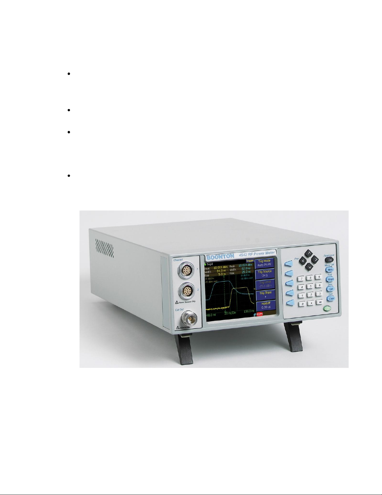
Figure 1-1. 4540 Series RF Power Meter
General Information

Boonton 4540 Series RF Power Meter
1-4
Dual Independent Channels. When equipped with the optional second measurement channel, the
instrument can display two pulsed RF signals simultaneously or one pulsed signal and one CW
signal. Each channel is calibrated and all channel parameters are channel-independent.
Balanced Diode Sensors. The balanced diode sensor configuration of most Boonton peak and CW
power sensors provides high sensitivity and even-order harmonic suppression. Low VSWR
minimizes mismatch errors. Frequency Calibration factors traceable to NIST standards are stored
in each power sensor’s EEPROM and downloaded to the instrument. A thermal sensor in each
peak power sensor tracks temperature variations.
Built-In Precision Calibrator. A 50 MHz step calibrator, traceable to NIST, enhances
measurement accuracy and reliability. The user-selectable automatic calibration routine calibrates
most sensors and the instrument in steps over the full dynamic range.
Adjustable Averaging. Random repetitive sampling at rates up to 5 GSa/sec followed by
waveform averaging with an exponential filter (performed on each point of the waveform) reduces
noise contribution and provides accurate, stable measurements. The number of repetitions to be
averaged can be adjusted to the smallest value that achieves the desired noise suppression, thereby
avoiding excessive averaging delays.
Automatic Waveform Analysis. The instrument can measure fifteen pulse parameters related to
power, time and/or frequency. All programmed measurements are made automatically and
displayed in text mode. Measurement information is available directly, eliminating the need for
interpretation by the user.
Single-Shot Measurements. The 50 MHz sampling rate yields a 5 MHz single-shot bandwidth (10
samples per pulse) for capturing and analyzing infrequent events in the time domain.
Flexible Remote Control. All instrument functions except power on/off can be controlled
remotely via the standard GPIB bus interface, USB port, or Ethernet LAN connection. Setup of
interface parameters is menu driven; front panel indicators keep the user informed of bus activity.
Remote control programming is performed using industry-standard SCPI programming syntax.
Stored Configurations. For applications in which the same instrument configurations are used
repeatedly, up to 25 complete setups can be stored and recalled by user-defined filename. The
instrument also provides built-in setups for many common signal types.
General Information

Boonton 4540 Series RF Power Meter
1-5
1.4 Accessories
Optional 4540 accessories that can be ordered from Boonton Electronics.
Table 1-1 Accessories for the 4540 Series
Selection Part Number Description
Standard
56810400A Line Cord (US)
96101301A Fuse Kit
98601300C Manual CD, Boonton Measurement Instruments (CD-ROM)
Optional
54600000A Fuse, USA (1.0A, Type T, 250V)
95403001A Rack Mounting Kit (Brackets only)
95403003A Rack Mounting Kit (Brackets with handles)
95105501A Type N to K Adaptor (for sensors with K-Connector®)
95600005A Peak Sensor Cable - 5 ft. (1.27 m)
95600010A Peak Sensor Cable - 10 ft. (2.54 m)
95600020A Peak Sensor Cable - 20 ft. (5.08 m)
95600025A Peak Sensor Cable - 25 ft. (6.35 m)
95600050A Peak Sensor Cable - 50 ft. (12.7 m)
95109101A CW Sensor Combo Cable/Data Adapter – 5 ft (1.27 m)
95109102A CW Sensor Combo Cable/Data Adapter – 10 ft (2.54 m)
95109001A CW Sensor Data Adapter – with connector for 41-2A cable
41-2A CW Sensor Cable – 5ft (1.27 m)
41-2A/10 CW Sensor Cable – 10ft (2.54 m)
41-2A/20 CW Sensor Cable – 20ft (5.05 m)
41-2A/50 CW Sensor Cable – 50ft (12.7 m)
41-2A/100 CW Sensor Cable – 100ft (25.4 m)
98406100A Instruction Manual 4540 Series, English (Printed w/binder)
Sensors
For sensor selection, refer to the BOONTON Sensor Manual.
1.5 Models, Options and Configurations
Model 4541. One measurement channel; sensor and calibrator connectors located on the front panel.
Model 4542. Two measurement channels; sensor and calibrator connectors located on the front panel.
Opt -02. Configuration option: Sensor connectors are located on the rear panel.
Opt -03. Configuration option: Calibrator connectors are located on the rear panel.
Opt -30. Warranty option: Extend factory warranty to 3 years
Option designations are appended to the instrument’s base model number. For example, Model 4542-0203 would be a two-channel instrument with sensor and calibrator connectors all on the rear panel.
Specials. Custom configurations have –S/n appended to the model number, where n is a unique number.
General Information

Boonton 4540 Series RF Power Meter
1-6
1.6 Specifications
Performance specifications for the 4540 Series are listed in Table 1-2.
Performance specifications for all Boonton power sensors are found in the Boonton Sensor Manual, which
may be ordered as Boonton p/n 98501900J.
Table 1-2 4540 Series Performance Specifications
(Specifications are subject to change without notice)
SENSOR INPUTS
RF Frequency Range: 1 MHz to 110 GHz*
Pulse Measurement Range: -50 to +20 dBm*
Modulated Measurement Range: -55 to +20 dBm*
CW Measurement Range: -70 to +44 dBm*
Relative Offset Range: ±300.00 dB
Vertical Scale: Logarithmic 0.1 to 50 dBm/div in 1-2-5 sequence
0.1 to 50 dBV/div in 1-2-5 sequence
0.1 to 50 dBmV/div in 1-2-5 sequence
0.1 to 50 dBµV/div in 1-2-5 sequence
Linear 1 nW/div to 50 MW/div in 1-2-5 sequence
1 nV/div to 50 MV/div in 1-2-5 sequence
Rise time/Video Bandwidth: 7 ns / 70 MHz*
Single-Shot Bandwidth: 5 MHz (based on 10 samples per pulse)
Pulse Repetition Rate: 30 MHz max (for internally triggered measurements)*
Minimum Pulse Width: 15 ns*
* SENSOR DEPENDENT
MEASUREMENT SYSTEM
Sensor inputs: One or two sensor measurement channels.
Measurement Technique: Random repetitive sampling system that provides pre and post-trigger
data as well as statistical histogram accumulation.
Maximum Sampling Rate: 50 Mega-samples/second on two channels simultaneously. (Equivalent
effective sampling rate of 5 Giga-samples/second)
Memory depth: 262,144 samples at max sampling rate
Vertical Resolution: 0.008%, 14-bit A/D Converter
TIME BASE
Time Base Range: 10 ns/div to 1 hr/div
Time Base Accuracy: 0.01%
Time Base Resolution: 0.2 ns
Time Base Display: Sweeping or Roll Mode
Trigger Delay Range: 10 ns - 500 ns timebases -4 ms to +100 ms
1 µs - 10 ms timebases 4000 divisions
20 ms - 3600s timebases -40 to +100 s
Trigger Delay Resolution: 0.02 divisions
General Information

Boonton 4540 Series RF Power Meter
1-7
Table 1-2 4540 Series Performance Specifications (continued)
(Specifications are subject to change without notice)
TRIGGER
Trigger Mode: Normal, Auto, Auto Pk-to-Pk, Free Run
Trigger Source: Channel 1 (internal)
Channel 2 (internal)
External Trigger
Internal Trigger Level Range: -40 to +20 dBm (sensor dependent)
External Trigger Level Range: ±5 volts, ±50 volts with 10:1 divider probe.
External Trigger Input Impedance: 1 Megohm in parallel with approx 13 pF, DC Coupled
Trigger Slope: + or –
Trigger Hold-off: 0.0 – 1.0 sec (10 ns resolution)
X-AXIS (Statistical)
Acquisition Mode: Continuous sample acquisition
Sampling rate: Configuration dependent.
Number of Histogram Bins: 16,384
Bin Power Resolution: <0.02 dB (statistical measurements)
Limit count: Adjustable, 2 – 4096 Mega-samples
Terminal action: Stop, flush and or decimate
Graph Presentation: Normalized CCDF trace (relative to average power)
Horizontal Scale: 0.1 to 5 dB/div
Horizontal Offset: ±50.00 dBr
Vertical Axis: 0.0001 to 100% (6 decades)
Text Measurements: Average, Peak and Minimum absolute power
Peak-to-Average and Dynamic Range ratios
CCDF table (Pk/Avg ratios at decade-spaced %CCDF intervals)
Cursor Measurements: Peak-to-Average ratio at specified %CCDF
%CCDF at specified Peak-to-Average ratio
Status Display: Total acquisition time (MM:SS)
Total acquired MegaSamples
General Information

Boonton 4540 Series RF Power Meter
1-8
Table 1-2 4540 Series Performance Specifications (continued)
(Specifications are subject to change without notice)
PULSE MODE OPERATION
Acquisition Mode: Discontinuous triggered sample acquisition
Trace Display: Power versus time swept trace (rolled trace for slow timebases)
Trace Averaging: 1 to 16384 samples per sweep data point, exponential
Markers (vertical cursors): Settable in time relative to the trigger position. Marker time position is
limited to displayed trace interval.
For each marker independently: Average, minimum and peak power at a single time offset
For a pair of markers: Average, minimum and peak power over the interval between markers
Power ratio between markers
The following automatic measurements are selectable in the power versus time (Pulse) mode:
Pulse width Pulse rise-time
Pulse fall-time Pulse period
Pulse repetition frequency Pulse duty cycle
Pulse off-time Peak power
Pulse ―on‖ power dB or Percent overshoot
Waveform Average power IEEE Top level power
IEEE Bottom level power Edge skew (Model 4542 only)
Edge delay
MODULATED MODE OPERATION
Acquisition Mode: Continuous (untriggered) sample acquisition
Trace Display: Power versus time rolled trace
Signal Filtering: ―Sliding window‖ filter; 0.002 to 16.0 seconds (fixed) or auto-filter
Channel Math: Displays the ratio, sum (power sensors) or difference (voltage sensors)
between channels or between a channel and a reference measurement
The following automatic measurements are performed continuously in Modulated Mode:
Filtered average power
Peak power
Minimum power
Peak to Average ratio
Dynamic range
General Information

Boonton 4540 Series RF Power Meter
1-9
Table 1-2 4540 Series Performance Specifications (continued)
(Specifications are subject to change without notice)
CALIBRATION SOURCE
Internal Calibrator
Operating Modes: Off, On CW
Frequency: 50.025 MHz ± 0.1%
Level Range: -60 to +20 dBm
Resolution: 0.1 dB
RF Connector: Type N
Source VSWR: 1.05 (reflection coefficient = 0.024)
Accuracy, 0C to 20C, NIST traceable:
At 0 dBm: ±0.055 dB (1.27%)
+20 to -39 dBm: ±0.075 dB (1.74%)
-40 to -60 dBm: ±0.105 dB (2.45%)
External Calibrator Model 2530 1 GHz Calibrator (Optional accessory. See Appendix B)
Auto-calibration: The Calibrator is used to automatically generate linearity calibration
data for peak power sensors. It is also provides test signals.
EXTERNAL INTERFACES
Remote Control: Complies with IEEE-488.1 and SCPI version 1993.
GPIB: Implements AH1, SH1, T6, LE0, SR1, RL1, PP0, DC1, DT1, C0, and E1.
USB: ―USB Device‖ Type B connector - does not require any power from host
LAN: TCP/IP Ethernet Programmable interfaces;
Multi I/O: BNC connector, user selectable for status, trigger, alarm or voltage output
Range: 0 to 10V (Analog unipolar), -10V to +10V (Analog bipolar), 0 or 5V (Logic)
Accuracy: ±100mV typical, ±200mV max, uncalibrated
Linearity: 0.1% typical
Ext Cal / VGA Out: HDB-15 connector. External calibrator control interface for Model 2530, or
video output for VGA compatible analog RGB video monitor.
General Information

Boonton 4540 Series RF Power Meter
1-10
Table 1-2 4540 Series Performance Specifications (continued)
(Specifications are subject to change without notice)
PHYSICAL AND ENVIRONMENTAL CHARACTERISTICS
Case Dimensions: 8.4W x 3.5H x 13.5D inches (21.3 x 8.9 x 34.3 cm), Half-rack width, 2U height
Weight: 7.7 lbs (3.5kg)
Power Requirements: 90 to 260 VAC, 47 to 63 Hz, 50W (70VA) maximum. Fuse 1.0A-T
Operating Temperature: 0 to 50 degrees C
Storage Temperature: -40 to +75 degrees C
Ventilation: Thermostatically controlled fan
Humidity: 95% maximum, non-condensing
Altitude: Operation up to 15,000 feet
Shock: Withstands ±5G, 11ms impulse in X, Y, and Z axes, as per EN 60068-2-27
Vibration: Withstands 2G sine, 1.25G random, as per EN 60068-2-6 and EN 60068-2-64
OTHER CHARACTERISTICS
Display: 4.0‖ Diagonal TFT color LCD, 320 x 240 pixels, CCFL Backlight.
Keyboard: 27 Key conductive rubber
Main Computer: 32-bit Floating Point embedded processor
DSP: 32-bit Floating Point DSP
Battery: One user-replaceable BR2325 Lithium coin cell (alkaline cells optional) for
maintaining non-volatile memory information. Typical life: 10 years (lithium)
Panel setup storage: Can save and recall 25 complete ―user‖ setups.
REGULATORY CHARACTERISTICS
CE Mark: Full compliance with the following European Union directives and standards:
Safety: Low Voltage Directive 2006/95/EC
EN 60950-1:2002
EMC: Electromagnetic Compatibility Directive 2004/108/EC
EN 61326:1997 + A1:1998 + A2:2001 + A3:2003
RoHS: RoHS Directive 2002/95/EC
Construction: Manufactured to the intent of MIL-T28800E, Type III, Class 5, Style E
General Information

Boonton 4540 Series RF Power Meter
2-1
2. Installation
This section contains unpacking and repacking instructions, power requirements, connection descriptions and preliminary
checkout procedures.
2.1 Unpacking & Repacking
The 4540 Series is shipped complete and is ready to use upon receipt. Figure 2-1 shows you the various pieces included in
the packaging and the order in which they are loaded into the container. Actual details may vary from the illustration.
Note Save the packing material and container to ship the instrument, if necessary. If the original materials (or
suitable substitute) are not available, contact Boonton Electronics to purchase replacements. Store materials
in a dry environment. Refer to the Physical and Environmental Specifications in Table 1-2 for further
information.
Figure 2-1. Packaging Diagram
Installation

Boonton 4540 Series RF Power Meter
2-2
Table 2-1 4540 Series Packing List
INSTRUMENT (See also Table 1-1)
4540 Series RF Power Meter
Line Cord
Fuse Kit
Boonton Instruction Manual CD
SENSOR(S) (packaged separately)
Sensor(s)
Sensor Cable(s)
Type N to SMA Adapter (if required)
BOONTON Sensor Manual CD
For bench-top use, choose a clear, uncluttered area. Ensure that there is at least 2" of clearance at the fan air intake on the
rear panel and the exhaust vents on the side panels. Pull-down feet are located on the bottom of the instrument. Rack
mounting instructions are provided with the optional rack mount kit.
2.2 Power Requirements
The 4540 Series is equipped with a switching power supply that provides automatic operation from a 90 to 260 volt, 47 to 63
Hz, single-phase, AC power source. Maximum power consumption is 50W and 70VA. For metric fuse sizes, use the metric
fuse kit supplied. Connect the power cord supplied with the instrument to the power receptacle on the rear panel. See Figure
3-2.
Caution Before connecting the instrument to the power source, make certain that a 1.0-ampere time delay fuse (type
T) is installed in the fuse holder on the rear panel.
Before removing the instrument cover for any reason, position the input module power switch to off (0 =
OFF; 1 = ON) and disconnect the power cord.
2.3 Connections
Sensor(s) Connect the sensor that covers the frequency range of the measurement to the CHANNEL 1 sensor
connector on the front (Standard) or rear (Optional) panel, as follows. Connect the sensor to the sensor
cable by aligning the red mark on each part and pressing the connectors together firmly. Connect the sensor
cable to the CHANNEL 1 Input, holding the red mark on the cable connector up. For two-channel
measurements, use the same procedures to connect the second sensor to the CHANNEL 2 Input.
Note If the sensor connector is not a type N, install the appropriate adapter (from the accessories kit) on the
calibrator output connector.
Installation
Boonton 4540 Series RF Power Meter
2-3
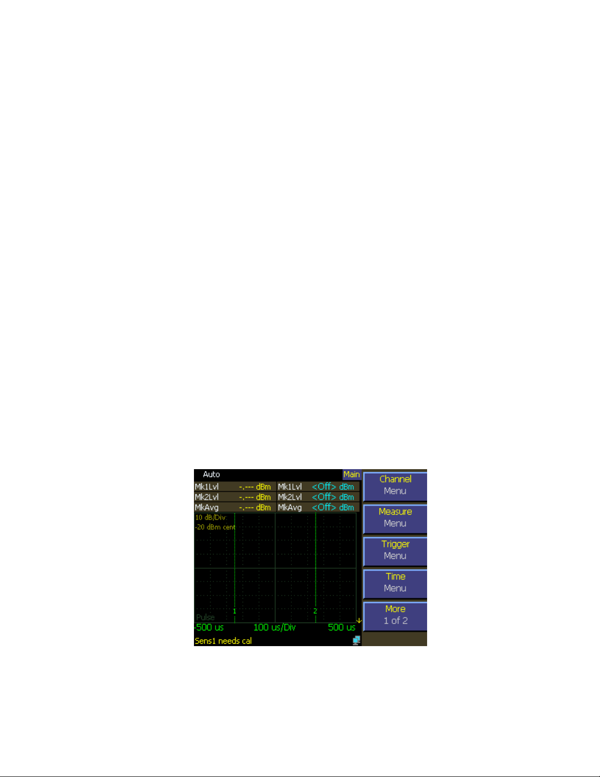
Figure 2-2. Typical Power-On Display
Trigger Most triggered applications can use the RF signal applied to the sensors for triggering. For measurements
requiring external triggering, connect the external trigger signal to the EXT TRIGGER BNC connector on
the rear panel.
Remote If the instrument is to be operated remotely using the GPIB (IEEE-488) bus, connect the instrument to the
bus using the rear panel GPIB connector and appropriate cable. For USB control, the rear panel USB
connector should be used, and for Ethernet control, connect to the rear panel LAN connector. In most
cases, it will be necessary to configure the interface using via the System > I/O Config menus.
2.4 Preliminary Check
The following preliminary check verifies that the instrument is operational and has the correct software installed. It should
be performed before the instrument is placed into service. To perform the preliminary check, proceed as follows:
1. Press the lower half (marked "0") of the power switch in the center of the power module on the rear panel.
2. Connect the AC (mains) power cord to a suitable AC power source; 90 to 260 volts AC, 47 to 63 Hz, with a capacity in
excess of 75 W. The power supply will automatically adjust to voltages within this range.
3. Press the upper half (marked "1") of the power switch in the center of the power module on the rear panel. If the
instrument was last in the standby state, it will enter standby mode. If it was last ―on‖ when power was removed, it will
return to the ON state.
4. If the 4540 is in standby mode (no display or power indication present), press the green ON/STBY key (marked with the
international 0/1 on/standby symbol) on the front panel to turn the instrument on. The display backlight should turn on
and there will be several clicks as the instrument boots.
5. After a self-check, the instrument will execute the application program. A bootup splash screen should briefly appear
that shows the instrument name, model number, and software version, and indicates boot status. After several moments
a screen similar to Figure 2-2 should be displayed.
Installation
Boonton 4540 Series RF Power Meter
2-4
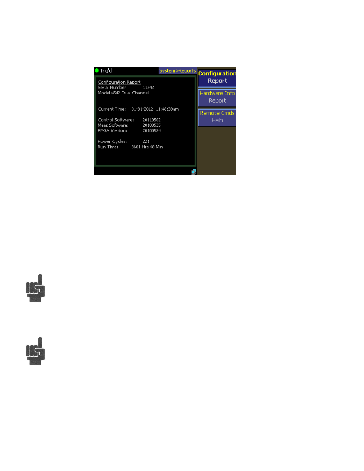
Figure 2-3. System > Configuration Report Display
6. On the front panel, press the Menu key followed by the More softkey, then on the softkeys, press System > Reports >
Configuration REPORT. A display similar to Figure 2-3 should appear.
7. Verify that the instrument serial number and model number shown are correct, and the correct number of channels
(single or dual) appears. If the channels are configured for non-standard length input cables, the expected sensor cable
length expected may also be appended. If any of this information appears incorrect, contact Boonton Electronics for
technical support.
8. Follow steps in Sections 3.4 and 3.5 to initialize and calibrate the instrument.
Note If the display does not appear or differs significantly from the illustrated display, try reinstalling the
instrument software as described in Section 7.5 "Software Upgrade". If this does not correct the problem,
contact Boonton Electronics for technical support.
Note You will not be able to perform measurements with the 4540 Series until an AutoCal procedure (see
Section 3.5) has been performed on the measurement channel. However, AutoCal data is saved when
power is removed, so AutoCal need not be repeated with each power-on.
Installation

Boonton 4540 Series RF Power Meter
3-1
3. Getting Started
This chapter will introduce the user to the 4540 Series. The chapter will identify objects on the front and rear panels, identify
display organization, list the initial configuration of the instrument after reset, demonstrate how to calibrate the sensors, and
provide practice exercises for front panel operation. For additional information you should see Chapter 4 "Operation."
3.1 Organization
Subsection 3.2 Operating Controls, Indicators and Connections identifies the control features and connections on the
front and rear panels.
Subsection 3.3 Monitor Display describes the data fields in the standard (graphic mode) display.
Subsection 3.4 Initialization explains how to turn the instrument on for the first time, connect a sensor, set the instrument up
for operation, and initialize it to a known state. See Table 3-3. for initialized parameters and their values.
Subsection 3.5 Calibration is critical to the proper operation of an instrument. The 4540 Series comes with a 50 MHz
programmable reference calibrator. Before making any measurement the sensor(s) may have to be calibrated with this
source.
Subsection 3.6 Making Measurements describes the different measurements modes of the 4540 Series.
3.2 Operating Controls, Indicators and Connections
Figures 3-1 and 3-2 illustrate the controls, indicators and connectors on the front and rear panels, respectively, of the
standard instrument. Refer to Table 3-1 for a description of each of the illustrated items. Connectors indicated by an asterisk
(*) may be front or rear-mounted, depending on the option selected. The function and operation of all controls, indicators
and connectors are the same on the standard and optional models.
Getting Started
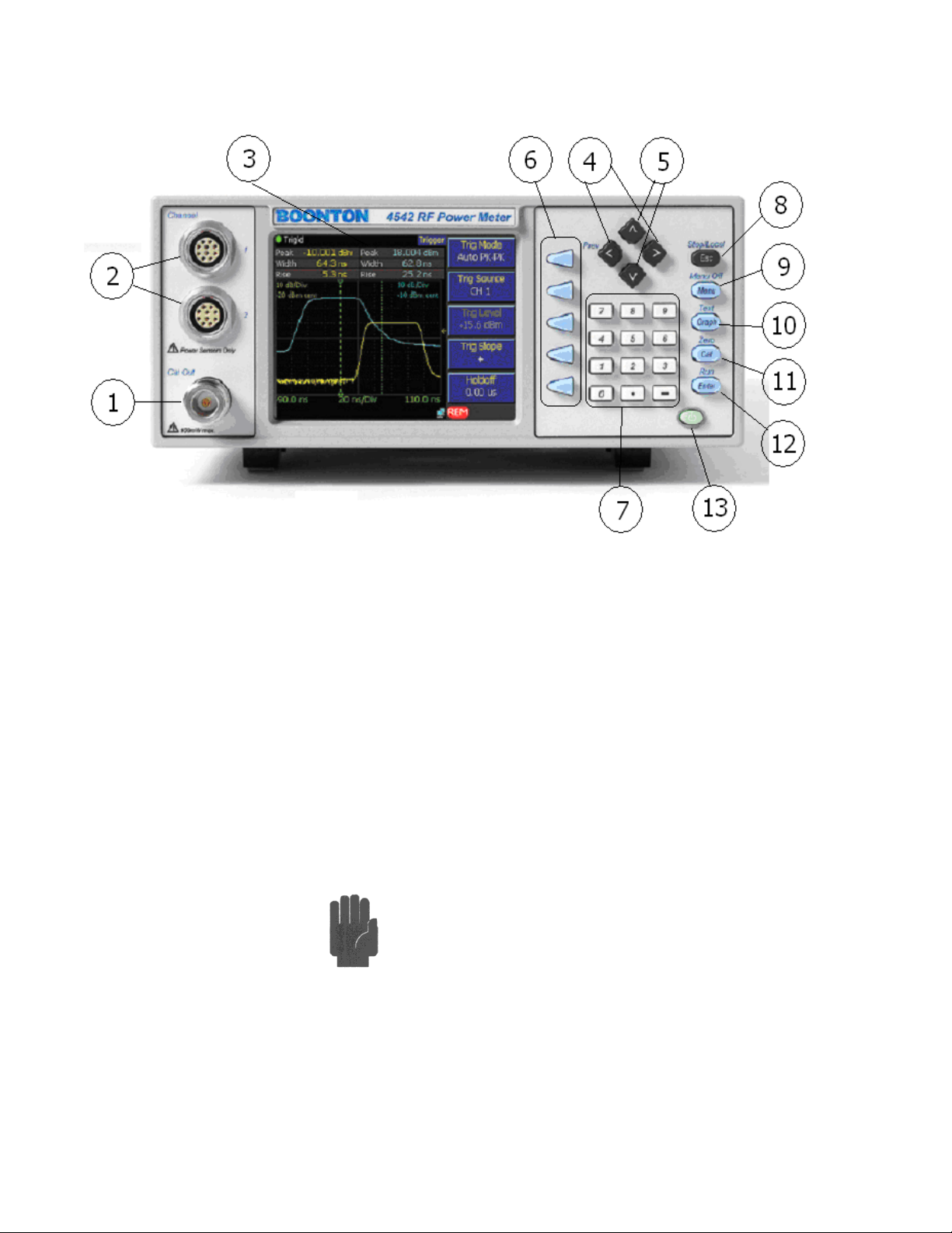
Boonton 4540 Series RF Power Meter
3-2
Figure 3-1. Standard 4540 Series RF Power Meter - Front Panel
Table 3-1 Operating Controls, Indicators and Connections
Reference #
Front Rear Nomenclature Function
1 1 Internal Calibrator The output of the built-in 50MHz programmable calibrator is available from a
Type-N connector located on the front, or optionally on the rear panel of the
instrument. This calibrator is used to automatically calibrate sensor offset and
linearity, and can also be used as a general purpose calibration signal source.
2 2 Sensor Inputs One or two sensor inputs are located on the front, or optionally on the rear panel
of the instrument. These are 10-pin precision connectors designed to accept only
Boonton Peak or CW power sensors and Boonton voltage probes.
Caution Do not attempt to connect anything other than a
Boonton power sensor, voltage probe or sensor adapter to the Sensor
inputs! The sensor inputs are not measurement terminals and cannot
be used for other than the intended purpose.
3 Display Screen Color LCD display for the measurement and trigger channels, screen menus,
status messages, text reports and help screens.
Getting Started
 Loading...