

Page 1

4540 Series
RF Power Meters
Quick Start Guide
V 1.02
PN: 98406000A
Page 2

4540 Power Meter
Quick Start Guide
CONTENT
SAFETY SUMMARY 3
LIMITED WARRANTY 4
4540 GETTING STARTED 5
CONTROLLING THE 4540 POWER METER 6
REAR PANEL 12
4540 OPERATION 15
INITIALIZATION 15
CALIBRATION 16
UPDATING FIRMWARE 18
MENU TREES 19
POWER MEASUREMENTS 28
MODULATED MODE 28
PULSE MODE 30
STATISTICAL MODE 32
4540 SPECIFICATIONS 34
ORDERING INFORMATION 35
4540 SENSORS 37
PEAK 37
CW 38
SENSOR COMPATIBILITY 39
GLOSSARY 40
CONTACT 42
PN: 98406000A © Copyright 2008 Boonton Page 2
Page 3
4540 Power Meter
Quick Start Guide
SAFETY SUMMARY
The following general safety precautions must be observed during all phases of
operation and maintenance of the Boonton 4540 RF Power Meter. Failure to comply
with these precautions or with specific warnings elsewhere in this manual violates
safety standards of design, manufacture, and intended use of the instruments.
Boonton Electronics Corporation assumes no liability for the customer’s failure to
comply with these requirements.
INSTRUMENT MUST BE GROUNDED
To minimize shock hazard, the instrument chassis and cabinet must be
connected to an electrical ground. The instrument is equipped with a three
conductor, three prong AC power cable. The power cable must either be
plugged into an approved three-contact electrical outlet or used with a threecontact to a two-contact adapter with the (green) grounding wire firmly
connected to an electrical ground at the power outlet.
DO NOT OPERATE THE INSTRUMENT IN AN EXPLOSIVE
ATMOSPHERE
Do not operate the instrument in the presence of flammable gases or fumes.
KEEP AWAY FROM LIVE CIRCUITS
Operating personnel must not remove instrument covers. Component
replacement and internal adjustments must be made by qualified
maintenance personnel only. Never replace components or operate the
instrument with the covers removed and the power cable connected. Even
with the power cable removed, dangerous voltages may be present. Always
remove all jewelry (rings, watches, etc.) and discharge circuits before
touching them. Never attempt internal service or adjustment of the 4540
unless another person, capable of rendering first aid and resuscitation, is
present.
DO NOT SUBSTITUTE PARTS OR MODIFY INSTRUMENT
Do not substitute parts or perform any unauthorized modification of the
instrument. Return the instrument to Boonton Electronics for repair to insure
that the warranty and safety features are maintained.
PN: 98406000A © Copyright 2008 Boonton Page 3
Page 4

4540 Power Meter
Quick Start Guide
LIMITED WARRANTY
Boonton Electronics warrants its products to the original Purchaser to be free from
defects in material and workmanship and to operate within applicable specifications
for a period of one year from date of shipment for instruments, probes, power
sensors and accessories. Boonton Electronics further warrants that its instruments
will perform within all current specifications under normal use and service for one
year from date of shipment. These warranties do not cover active devices that have
given normal service, sealed assemblies which have been opened, or any item
which has been repaired or altered without Boonton’s authorization.
Boonton’s warranties are limited to either the repair or replacement, at Boonton’s
option, of any product found to be defective under the terms of these warranties.
There will be no charge for parts and labor during the warranty period. The
Purchaser shall prepay inbound shipping charges to Boonton or its designated
service facility and shall return the product in its original or an equivalent
shipping container. Boonton or its designated service facility shall pay shipping
charges to return the product to the Purchaser for domestic shipping addresses. For
addresses outside the United States, the Purchaser is responsible for pre-paying all
shipping charges, duties and taxes (both inbound and outbound).
THE FOREGOING WARRANTIES ARE IN LIEU OF ALL OTHER WARRANTIES,
EXPRESS OR IMPLIED, INCLUDING, BUT NOT LIMITED TO, THE IMPLIED
WARRANTIES OF MERCHANTABILITY AND FITNESS FOR A PARTICULAR
PURPOSE. Boonton will not be liable for any incidental damages or for any
consequential damages, as defined in Section 2-715 of the Uniform Commercial
Code, in connection with products covered by the foregoing warranties.
PN: 98406000A © Copyright 2008 Boonton Page 4
Page 5
4540 Power Meter
Quick Start Guide
4540 GETTING STARTED
Congratulations and thank you for choosing Boonton. Your new 4540 Power Meter
ranks among the most powerful instruments in its class. Our new family of Boonton
CW and Peak Power Meters currently consists of the single channel 4541 and the
dual-channel 4542. For simplification both instruments are referred to in this manual
as 4540.
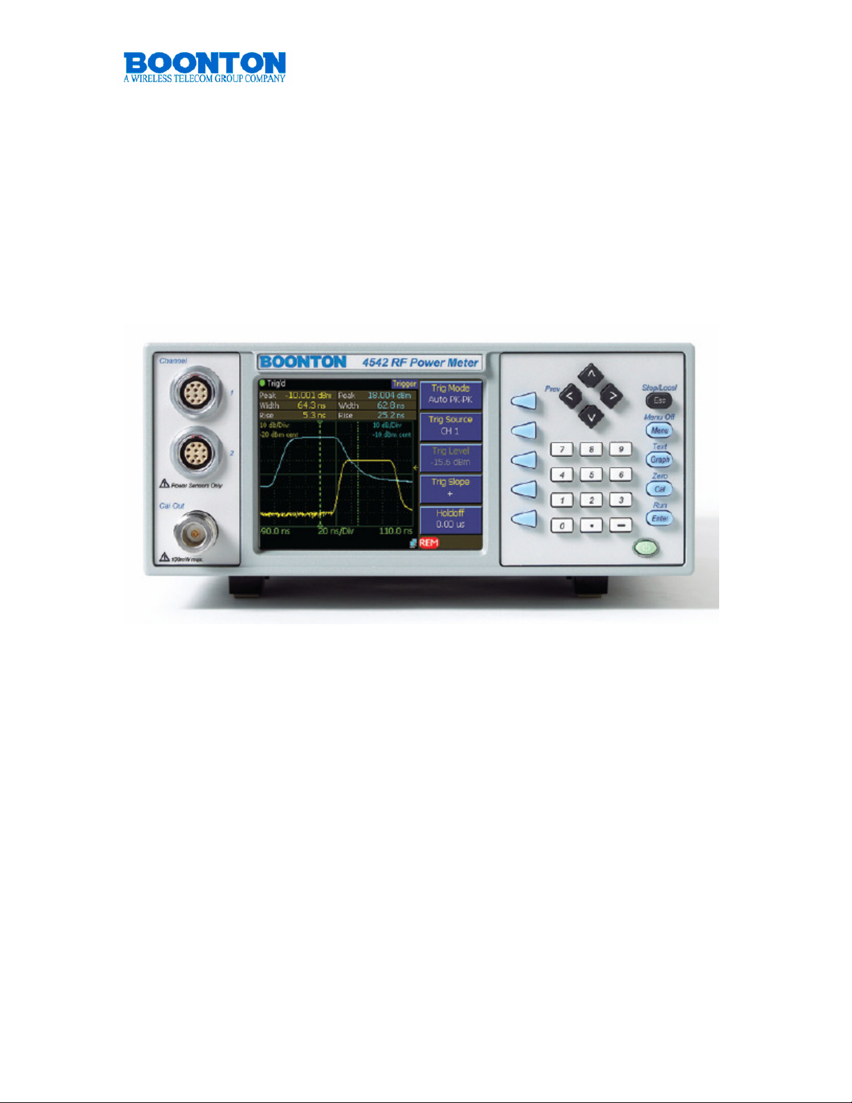
4540 Front Panel
The Boonton 4540 Series Power Meter is the instrument of choice for capturing,
displaying and analyzing RF power in both the time and statistical domains.
Applications include pulsed RF signals such as radar, TDMA and GSM,
pseudorandom or noise-like signals such as CDMA, WLAN and WiMAX.
The 4540 Series is available as a single or dual channel RF Power Meter that can
measure modulated or CW signals using peak and average Boonton Power sensors.
The 4540 Series has three operating modes: Pulse, Statistical, and Modulated/CW.
Features include:
• High Bandwidth Wide Dynamic Range Sensors
• Intuitive User Interface
• 4” color LCD display
• 200 psec. time resolution
• Statistical analysis including CCDF
• Text view of 2x 15 time and power measurements parameters simultaneously
• GPIB, USB and LAN standard
PN: 98406000A © Copyright 2008 Boonton Page 5
Page 6

4540 Power Meter
Quick Start Guide
CONTROLLING THE 4540
On / Standby
Pressing the On/Standby key switches the power meter between on
and standby modes. When in standby, some circuitry remains powered
to reduce drain on the battery used to maintain the instrument’s realtime clock. The instrument’s current operating state is automatically saved before
entering standby.
Control Keys
Control keys allow maneuvering through the menus of the 4540. All keys are multi
functional and provide functionality depending on the current status of the
instrument. An additional <Fn> key is not necessary, since the system will
automatically assume the wanted function.
Esc / Stop / Local
Aborts any operation in progress when in Menu Mode or Zero/Cal Mode.
Pressing Esc / Stop / Local while the instrument is running causes the
process to stop. Pressing it when already stopped will clear the screen and
reset all measurement values. Pressing Esc / Stop / Local when the
instrument is in remote mode (the GPIB, LAN or USB has control of the
instrument and keyboard entry is disabled) will return it to local mode (the instrument
is under keyboard control) unless the local lockout command, LLO, has been issued
by the controller.
Pressing the Esc / Stop / Local key performs ONE of the following prioritized
operations, depending upon the current instrument state. The list is evaluated from
the top, and once a condition is met, its action is taken and the rest of the list is
ignored.
• Enters Local control mode if the instrument is in Remote control mode (unless
the Local Lockout remote command has been sent)
• Aborts a sensor Cal, Zero or Autocal operation that is in progress
• Clears error message and queue if any errors are present (red error message
text shown)
• Aborts display of report screen or error dialog being shown
• Aborts any numeric input or menu pick list entry that is in progress
• Deselects any selected menu button
• Stops measurement acquisition if running
• Clears acquired measurement if acquisition is already stopped
PN: 98406000A © Copyright 2008 Boonton Page 6
Page 7

4540 Power Meter
Quick Start Guide
Menu / Menu Off
Places the instrument in Menu Mode to allow navigation of the menu
structure. Menu soft keys appear at the right side of the screen. Pressing
and holding Menu / Menu Off while already in Menu Mode switches the
menu display off and provides larger screen area for measurements, thus
allowing larger display in text mode and higher resolution in graph mode.
Graph / Text
Pressing Graph / Text places the instrument in Graph Mode to display the
current measurement waveforms (traces) in a graphical format. Pressing
Graph / Text while in Graph Mode toggles to numeric/text display of the
measurement.
Cal / Zero
Places the instrument in Sensor Zero/Calibration Mode and displays a menu to allow
automatic sensor offset and gain adjustments using the built-in 50MHz calibrator or
an external calibrator, as well as to permit control of the internal or external
calibrator.
• Pressing the Cal / Zero key displays the sensor calibration menu for the most
recently active calibration channel, or the first active channel. If no channels
are active, the menu defaults to Channel 1.
• Pressing the key again will display the menu for the next active channel, if
any.
A channel is considered “active” if it is installed in the instrument and a sensor is
connected. The calibration menu contains soft keys for sensor Zero, Fixed cal or
Autocal, as well as submenus to permit selection and control of the built-in or
external RF calibrator
Enter / Run
Activates a menu selection or completes update of a parameter in Menu Mode or
Zero/Cal Mode. Pressing Enter/Run while stopped in measurement mode will start
(or restart) the measurement process.
Pressing the Enter / Run key performs ONE of the following prioritized operations,
depending upon the current instrument state. The list is evaluated from the top, and
once a condition is met, its action is taken and the rest of the list is ignored.
• Completes a numeric or menu pick list entry that is in progress
• Starts measurement acquisition if stopped
• Clears and restarts measurement acquisition if already running
PN: 98406000A © Copyright 2008 Boonton Page 7
Page 8
4540 Power Meter
Quick Start Guide
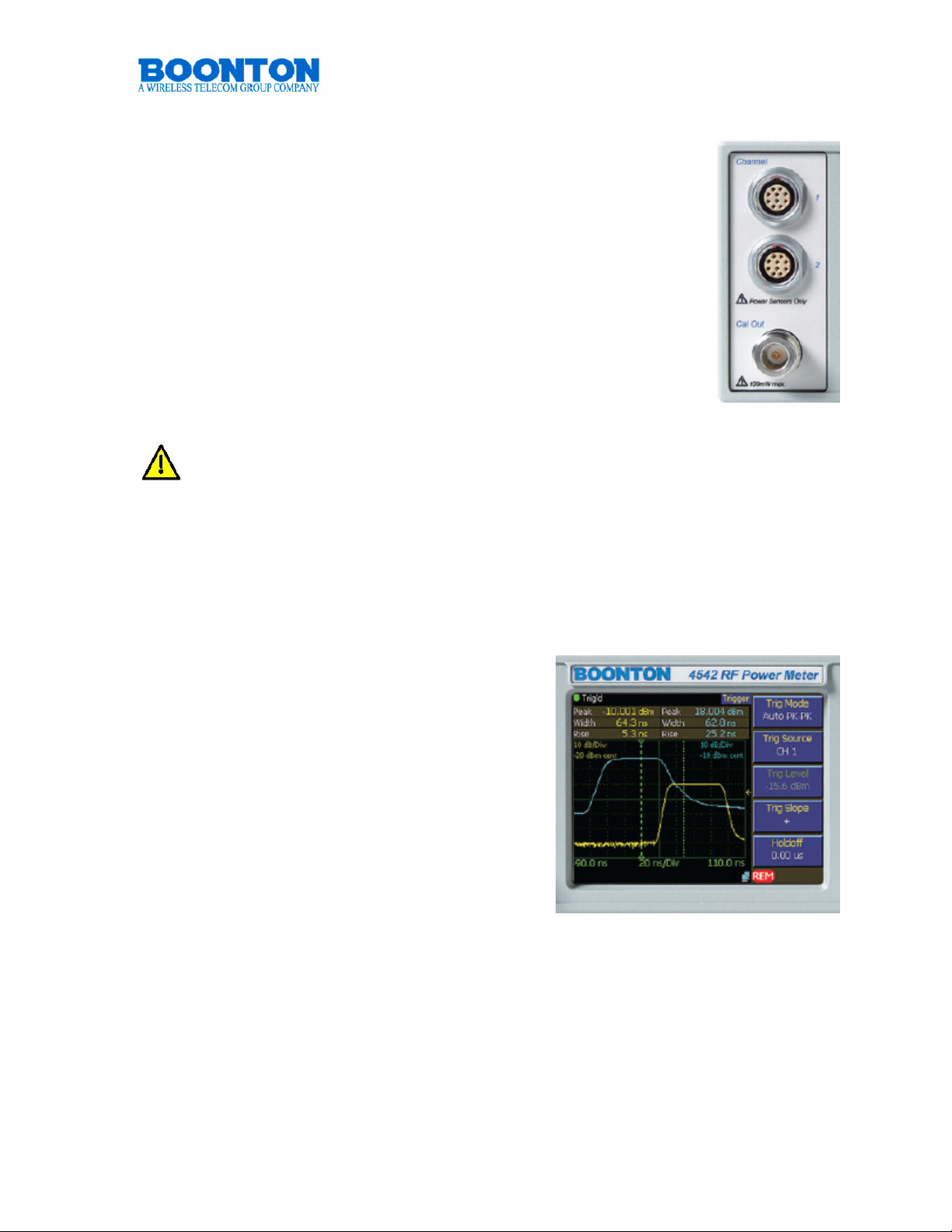
Measurement Channels
4541 consists of one, 4542 of two measurement channels. Both
systems are optionally available with the sensor and calibrator
connectors located on the rear panel. Such a configuration can be
beneficial for rack mount ATE applications The measurement
channels provide an RF range from 1 MHz to 110 GHz and offer a
dynamic range of -55 dBm to +20 dBm for Peak Power
measurements and -70 dBm to +44 dBm for CW Power
measurements. Actual measurements are dependent on the
sensors used. Both channels support a variety of Boonton Power
Sensors. A comprehensive list is provided in chapter 4540
Sensors (page 35-37). Sensors connected to the 4540 are
automatically detected.
Do not connect other components or power sensors of other manufacturers
to the measurement inputs. Damage will occur.
Calibrator Output
All 4540 series Peak Power Meters provide a build-in 50 MHz, -60 dBm to +20 dBm,
0.1 dB step calibrator. The calibrator allows automatic sweeping as well as manual
setting of output values. It is used to automatically calibrate sensor offset and
linearity, and can also be used as a general purpose calibration signal source.
Display
The quarter VGA display of the 4540 has a
resolution of 320x240 pixels. It provides a
detailed reading especially when in Graph
Mode. The display of the soft keys functions
can be switched on or off during
measurements. Switching off or hiding the soft
key functions increases the display area for
waveforms by another 25%. A VGA monitor
can be connected via the VGA connector found
on the rear panel of the 4540. The full screen
content will be displayed with a 320 x 240
resolution.
PN: 98406000A © Copyright 2008 Boonton Page 8
Page 9

4540 Power Meter
Quick Start Guide
Soft keys
The five Menu Soft Keys are used to navigate the menu
hierarchy and to view or modify instrument settings. These keys
are active only when the menu is displayed. Each key has a
corresponding “menu box”, that changes depending upon which
menu is visible. Pressing the soft key may perform any one of
several operations, depending on the particular menu. In some
cases, the pressing the key will cause that menu item to become
“active” – the menu box will appear to be pressed in.
• Action: causes an action to be initiated, for example
“AutoCal Start”. The menu box flashes briefly when
pressed and the selected action occurs.
• Submenu: navigates down one level in the menu tree to a submenu of the
current menu. The current path down into the menu hierarchy is shown in the
Path display at the top of the screen.
• Toggle: pressing the key will toggle a value between two or more fixed
values, for example “On” or “Off”. The menu box flashes briefly when
pressed, and the selected item will toggle to the next value.
• Picklist: pressing the key will display a pop-up box showing a list of values
that may be selected for the menu parameter. The ▲ and ▼ (up and down
arrow) keys may be used to move the selector between values. Pressing
Enter accepts the selection, and Esc aborts.
• Numeric Entry: pressing the key selects the menu item for entry. The menu
box appears depressed and numeric entry is now active for that item. The ▲
and ▼ keys can be used to increment or decrement the current value, or the
numeric keypad can be used to enter a new value directly. Pressing the
menu softkey again will deselect the menu item. See the “numeric entry”
section below for more details.
PN: 98406000A © Copyright 2008 Boonton Page 9
Page 10

4540 Power Meter
Quick Start Guide
Up and Down Arrow Keys
Pressing the ▲ or ▼ key performs ONE of the following prioritized
operations, depending upon the current instrument state. The list is
evaluated from the top, and once a condition is met, its action is
taken and the rest of the list is ignored.
• Increments or decrements a numeric entry menu parameter, either by a
default value, or by one digit place when in digit editing mode.
• Scrolls the selector up and down a menu picklist
• Scrolls through available display “pages” or a the displayed table of
measurements and parameters in text mode
• Scroll between the first-level submenus in the menu hierarchy. For example,
if the Trigger menu is selected, pressing ▼will move directly to the Time
menu, which is adjacent to the Trigger menu in the tree. This eliminates the
need to return to the top of the tree and select the Time menu from there.
Left and Right Arrow Keys
Pressing the ◄ or ► key performs ONE of the following prioritized
operations, depending upon the current instrument state. The list is
evaluated from the top, and once a condition is met, its action is
taken and the rest of the list is ignored.
• When menu containing a numeric parameter is selected, the ◄ and ► keys
may be used to highlight a particular digit to edit.
• The ◄ key serves as a “Previous” key during menu operation, and will
navigate back to the next higher menu in the hierarchy unless the user is in
digit editing numeric entry mode
PN: 98406000A © Copyright 2008 Boonton Page 10
Page 11

4540 Power Meter
Quick Start Guide
Numeric Entry
There are three ways to modify the value of a selected numeric
menu item.
• Default Increment/Decrement – Pressing the ▲ or ▼ keys
will increment or decrement the parameter by a default value.
In most cases, this default is fixed. At other times, it may
depend upon the current state instrument state, such as the
display or time base settings. If the key is held, the increment/decrement will
auto repeat slowly, then at an increasing rate. The display and trace is
updated each time the value changes, so it is possible to view the effects of
changing the parameter in real time without needing to press Enter.
• Single-digit Increment/Decrement – this mode allows the parameter’s value to
be incremented or decremented by a selectable amount by highlighting the
desired digit. The mode is entered by pressing the ◄ key, which will display
a cursor under the rightmost (least significant) digit. Pressing ◄ or ► moves
the digit cursor, and pressing ▲ or ▼will increment or decrement the
highlighted digit by one. Pressing ◄ beyond the leftmost digit will add leading
zeroes to permit the number to become larger. Again, the display is updated
each time the value changes, so the changes will be visible in real time –
there is no need to press Enter each time.
• Direct Entry – The numeric keypad can be used to directly enter numbers.
Key in the desired number and press Enter to input a new value in the current
or default units. When parameters need to be entered in different units or
with unit prefixes (such as milliseconds or microseconds), entries are
completed by pressing the soft keys showing the desired units rather than the
Enter key.
PN: 98406000A © Copyright 2008 Boonton Page 11
Page 12
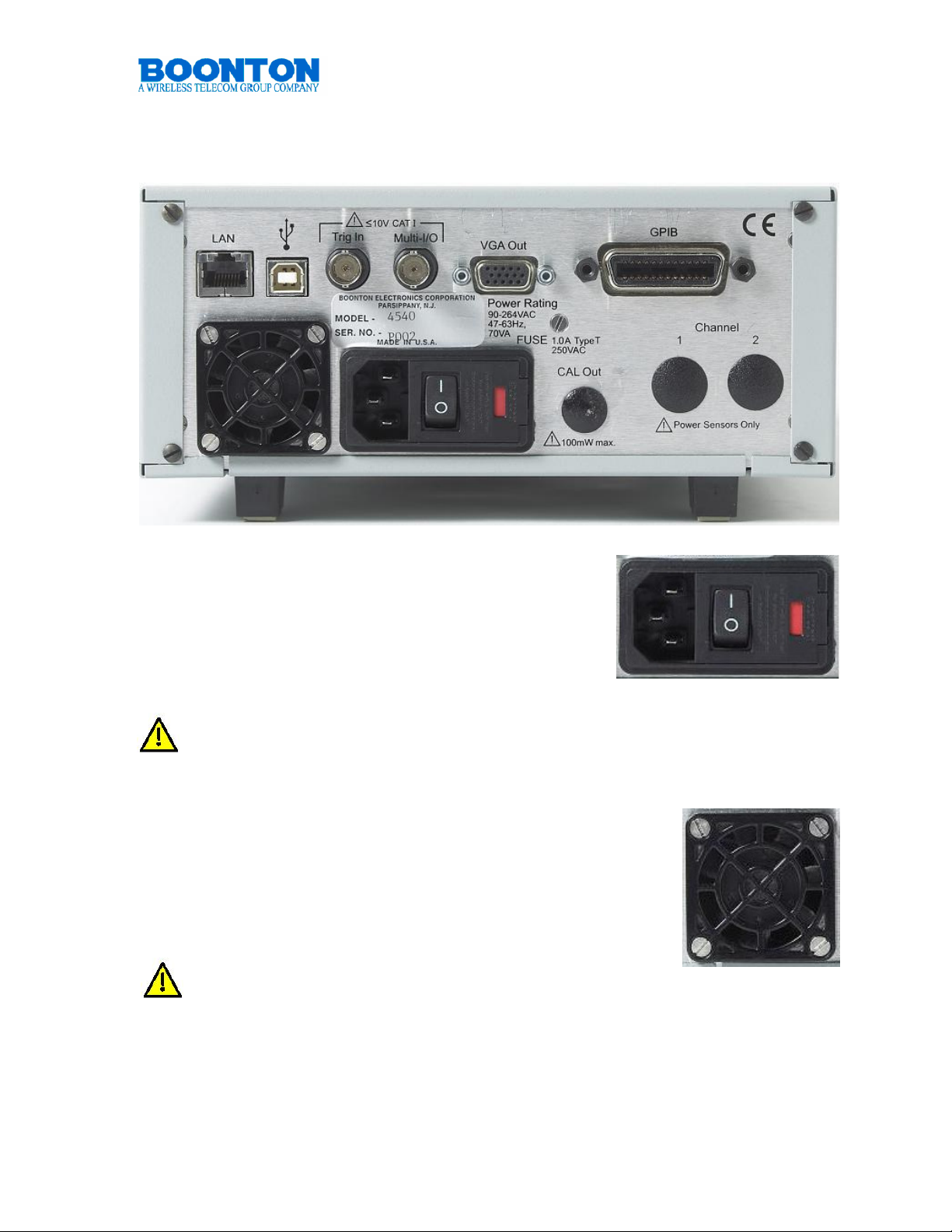
4540 Rear (Interface) Panel
4540 Power Meter
Quick Start Guide
Main Power Switch
The 4540 accepts any AC power from 90 to 264 V (47
to 63 Hz). No voltage switching is required. Power
consumption is maximal 70 VA. Switching the power
on sets the 4540 into Standby-Mode. To start the
instrument, press also the green [On] button at the
front panel. The fuse is a 1.0 A T type.
Never use different fuses than specified. Damage may occur.
Fan
The 4540 Power Meters is an instrument designed for
performance. While the power consumption is minimized, the
components of the instrument generate heat that needs to be
removed. The 4540 fan is pushing cold air into the system. The
heated air leaves at the air vents right and left side of the 4540.
Never interrupt the air stream by placing other articles
too close to the fan or the vents. Always keep 15 cm/ 4
inches free space for the fan and 5 cm / 2 inches for
each side vent.
PN: 98406000A © Copyright 2008 Boonton Page 12
Page 13
4540 Power Meter
Quick Start Guide
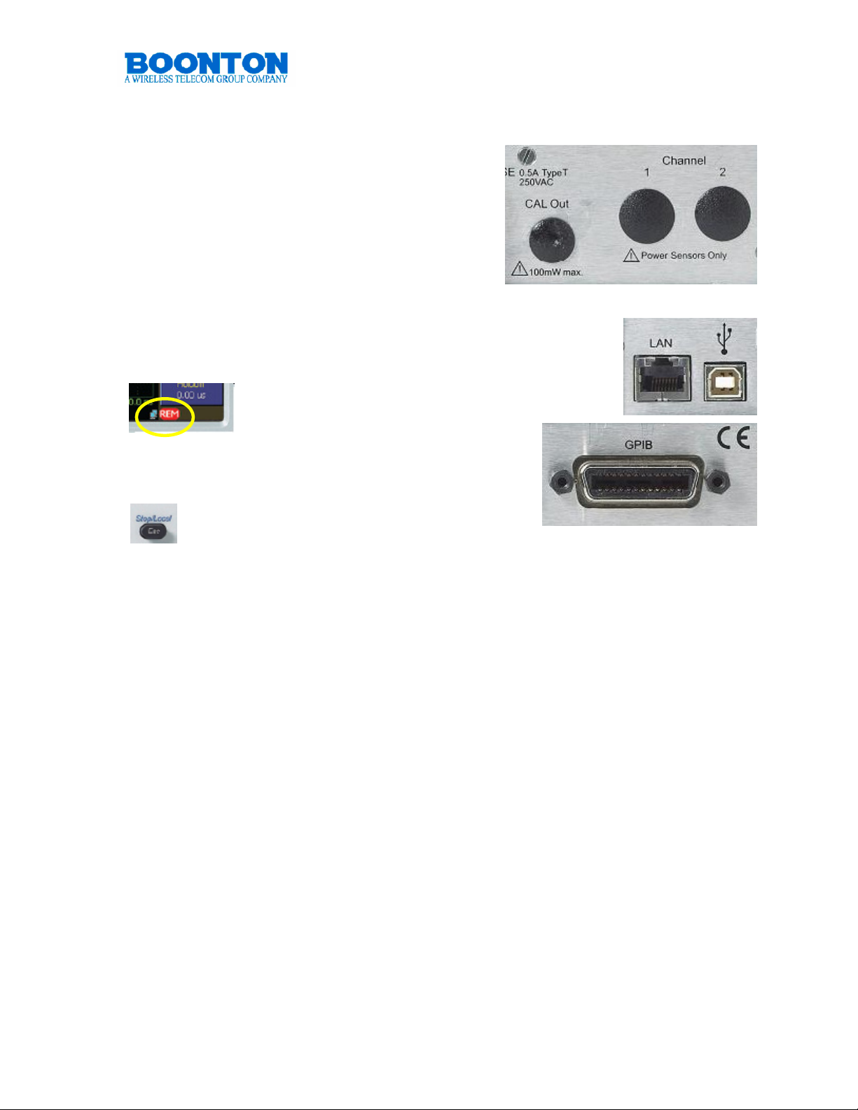
Rear Panel Measurement and Calibrator
Connectors (Optional)
The 4540 can be ordered with measurement
channel(s) and/or the calibrator output mounted
on the rear panel. This is usually handy when
the instrument is integrated in systems like ATE.
Communication interfaces.
4540 comes standard with LAN (Ethernet), USB and GPIB
interface. All interfaces can be used to remote control the
instrument. When either GPIB, LAN or USB assume control of
the instrument, the keyboard entry is
automatically disabled. A remote sign will be
shown at the lower right side of the
screen during remote operation.
Pressing Esc / Stop / Local when the instrument is
in remote mode will return it to local mode
(the instrument is under keyboard control).
LAN allows DHCP or fixed (IP / Subnet) setting mode.
USB is compatible to V 1.1 and 2.0
GPIB interface supports AH1, SH1, T6, LE0, SR1, RL1, PP0, DC1, DT1, C0, and
E1.
LAN, USB and GPIB ports are also used for 4540 firmware updates.
PN: 98406000A © Copyright 2008 Boonton Page 13
Page 14

4540 Power Meter
Quick Start Guide
VGA Out
Information displayed at the front screen is also provided at the
VGA Out interface. VGA out allows to connect any VGA, SVGA
and XVGA monitors. The resolution is equivalent to the 4540
screen resolution 320 x 240 pixels.
Trigger In
When [Trigger Source External] is selected, power measurements can
be triggered by external events. The trigger level can be set between 5V and +5 V, thus supports a variety of logic level signals.
Never exceed +/- 10V DC at this input or instrument
damage will occur.
Multi I/O
The rear-panel BNC connector is a programmable analog output is
available for connection to an external chart recorder or other device.
The output voltage range is unipolar or bipolar 10 volts. The output
produces a voltage proportional to signal level, or a logic level status
voltage for signaling when the RF power is above or below preset “alarm limit”
thresholds. Recorder output parameters can be configured through the menu. The
connector will be used in the future for special instrument functions.
PN: 98406000A © Copyright 2008 Boonton Page 14
Page 15

4540 Power Meter
Quick Start Guide
4540 OPERATION
INITIALIZATION
The procedures presented in this section will initialize the Boonton 4540 and prepares it for operation. Steps 1 through 3 should be performed every time you turn on
the instrument. Step 4 only needs to be performed when you wish to return the
instrument operation to a known state. This usually occurs after turning the
instrument on or at the beginning of a new test.
Step Procedure
1. If the main power is off, press the power switch located on the rear panel.
Then press the Pwr On key at the front panel. After a self-check, the
instrument will execute the application program. A brief initialization screen
will appear which shows the instrument name, model number, and software
version. During that period the fan varies its speed and relays are audibly
switching, this is normal. After several moments the main measurement
screen will appear. If it is necessary to change the sensor installed on the
instrument, perform Steps 2 and 3.
2. Connect the sensor to the sensor cable by aligning the red mark on each part
and pressing the connectors together firmly.
When selecting a sensor, be sure you know the power range.
Extended operation beyond the sensor’s specified upper power limit
may result in permanent change of characteristics or damage.
3. Connect the sensor cable to the Channel 1 input (holding the red mark UP).
When the sensor is connected, the instrument will download the factory
installed calibration data from the sensor memory. In general, when any
sensor error message occurs, disconnect and reconnect the sensor and
press [Esc]. If the message persists, refer the problem to Boonton Electronics
for technical support.
4 . Press the Factory Defaults soft key in the MAIN / MORE / SETUP sub-menu
to initialize the default operating parameters of the 4540 Power Meter.
Note: The Factory Defaults soft key does not affect parameters selected for the
GPIB Bus, RS-232, display colors, or the printer configurations.
PN: 98406000A © Copyright 2008 Boonton Page 15
Page 16

4540 OPERATION
CALIBRATION
Power sensors require calibration before they can be used. Calibration ensures most
accurate power measurements. The 4540 Power Meter reminds users when sensor
calibration is due. This can happen if it has not yet performed or after a period of
time in which temperature changes may have occurred.
The 4540 comes with a built in calibrator but also allows for utilizing an
external calibrator. To prepare for the internal calibrator, ensure that the
following settings are selected.
1. Choose the Calibration menu by pressing the [Cal] button.
2. Select Calibrator: Internal
3. Select: Cal Output: On
PN: 98406000A
Page 17

4540 Power Meter
Quick Start Guide
Performing Calibration
1. Connect the sensor 1 to Channel 1 of the 4540.
2. Connect the sensor 2 to Channel 2 of the 4540 – if applicable.
Note: To ensure accurate calibration of Peak power sensors it is strongly
recommended to allow a warm-up and stabilization period of at least 3 minutes,
after a sensor has been connected to a powered-on instrument. For best
possible calibration we recommend to extend this period to 15 minutes.
Calibrating Sensor 1
3. Connect sensor 1 to the Cal Out connector.
4. Press Cal Button to select the Calibration Menu
5. Display shows the cal menu with “CH1>Calibration” at the top.
6. Press AutoCal Start
Calibration of sensor
connected to CH1 is performed
7. Disconnect Sensor 1 from
Cal Out
On a 4542 dual channel
system with two sensors
Calibrating Sensor 2
8. Connect Sensor 2 to the
Cal Out connector.
9. Press Cal Button again to
select the Calibration Menu
10. Display shows the cal menu with “CH2>Calibration” at the top.
11. Press AutoCal Start
Calibration of sensor connected to CH2 is performed
12. Disconnect Sensor 2 from Cal Out
Note: AutoCal selects calibration points based on the dynamic range of the
connected sensor. AutoCal will extend the calibration range typically about 3dB of
the sensor specification.
PN: 98406000A © Copyright 2008 Boonton Page 17
Page 18

4540 OPERATION
4540 Power Meter
Quick Start Guide
FIRMWARE UPDATE
The Firmware of the 4540 is updated periodically. New firmware versions are free
and can be downloaded from our Web site. Firmware of 4540 Power Meters can be
easily field updated via USB, Ethernet or GPIB Bus.
Requirements:
PC
Web access to download the firmware
USB:
USB cable (V1.1 and V2.0)
Ethernet:
2 Ethernet cables
Hub or Switch
or
PC direct
Cross Wired Ethernet Cable
or
any LAN connection
GPIB:
PC with GPIB interface
GPIB Cable
Downloading software and the latest 4540 firmware is available at our Web site:
http://www.boonton.com/software/support-software.html
This URL will offer a form that needs to be filled out. It links to a page to download a
zip file: Upd4540_YYYYMMDD.zip
This zip file contains the installer utility (Installer4540.exe), the update data file
(Upd4540_YYYYMMDD.btn, and installation instructions (Upd4540.txt)
We strongly recommend update your 4540 RF Power Meter always with the
latest firmware. This provides best possible performance, optimal reliability
and extended feature set of the instrument.
PN: 98406000A © Copyright 2008 Boonton Page 18
Page 19

4540 OPERATION
4540 Power Meter
Quick Start Guide
Boonton’s 4540 is a designed for best performance but at the same time for
ergonomic aspects and user convenience. Thus, menus of the systems are not rigid
but take particular configurations and measurement conditions into account, this
includes measurement modes and sensors connected. Also the sensor type, CW or
Peak, determines different menu presentation. Soft keys may change – in a way that
the instrument assumes what the user wants to press next.
Boonton made the menu structure of the 4540 as intuitive as possible, offering
manual operation of the 4540 with as few as possible key strokes – independent of
the mode. Users who worked with the unit became comfortable within minutes and
became excited about the swift way to operate this power meter and perform
measurements.
The example shows the Main menu twice. The first screen shot refers to a
modulated measurement that a user may have selected, the second presentation
refers to a statistical measurement. Soft keys change in a way that the user would
MENU TREES
expect. Modulated measurement
provides Trigger and Time submenus, while statistical
measurements present the Stat
Mode menu.
PN: 98406000A © Copyright 2008 Boonton Page 19
Page 20

MENU TREE: MAIN
Main
4540 Power Meter
Quick Start Guide
Channel
Measure
Trigger
Time *
Channel 1
Channel 2
On / Off
Mode
Clear
Single Sweep
Auto Setup
Mode
Source
Level
Slope
Hold off
Time Base
Position
et sqq.“Channel” tree
et sqq.“Channel” tree
Pulse | Modulated | Statistical
Auto Pk-Pk | Auto | Normal | Free Run
CH 1 | CH 2 | Ext
Num. Input: -50 to + 20 dBm
+ | -
Num. Input: 0 us to 1s (0.01us resolution)
Num. Input: 10 ns to 1 min / Div
Middle | Right | Left
or
+/- 30 div
or
Stat * Horiz. Scale
More
* Depends on Measurement Mode Pulse & Modulated: Time, Statistical: Stat
Trig delay
Position Cntrl
Horiz. Offset
Term Options
Cursors
et sqq.” Main / More” tree
Num. Input: 0 ns to 100 us (dep. on time base setting)
Preset | Vernier
Num. Input Up/Dn: 0.1 to 5 dB / Div
Num. Input: -50.00 to +50.00 dB
et sqq.”Stat Mode” tree
et sqq.”Stat Mode” tree
PN: 98406000A © Copyright 2008 Boonton Page 20
Page 21

4540 Power Meter
Quick Start Guide
MENU TREE: CHANNEL
Channel
On / Off
Vert. Scale, Up/Dn: 0.1 to 50 dB / Div
Vert. Center, Num. Inp. : -100dBm to +100 dBm
Calibration
AutoCal: Start
Fixed Cal: Start
Zero Cal: Start
Sel. Calibrator: Int | Ext
Cal. Control Cal. Output: On/Off or On | Off CW | Int Pls | Ext Pls
Level, Num Inp: -60.0 to +20.0 dBm
Sel. Calibrator: Int | Ext
Status Displ: Select
Pulse
Polarity: + / -
Duty Cycle: 10% to 90%
Period: 100us | 1ms | 10 ms
Preset
or
Polarity: + / -
Puls Width: 0.000ms to 66.000 ms
Puls Period: 0.000ms to 132.000 ms
Variable
Extensions
et sqq.” Channel / Extensions” tree
PN: 98406000A © Copyright 2008 Boonton Page 21
Page 22

4540 Power Meter
Quick Start Guide
MENU TREE: CHANNEL / EXTENSIONS
Channel
Extensions
Units: dBm | Watts | Volts | dBV | dBmV | dBuV
Corrections
1
Filter State: On | Off | Auto
or
Averaging, Up/Dn: 1 to 16384
2
1
Filter Time: 0.000 to 16.000s
or
Define Pulse Distal: 0.00 to 99.99%
2
dB Offset, Num Inp.: +/- 200 dB
Frequency Cal Factor, Num Ino.: +/- 3.00 dB
Temp Comp: On | Off
Mesial: 0.00 to 99.99%
More 1/2
1
Stat Mode, Modulated Mode or CW Sensor
2
Pulse Mode – Pk sensor only
3
CW sensor only
Proximal: 0.00 to 99.99%
Pulse Units: Watts | Volts
Video BW: High | Low
Peak Hold: Off | On
Frequency, Num Inp.: Sensor dependent
Duty Cycle
3
PN: 98406000A © Copyright 2008 Boonton Page 22
Page 23

4540 Power Meter
Quick Start Guide
MENU TREE: MAIN / STAT MODE
Main
Channel
Measure
Trigger
Stat Mode
et sqq.“Channel” tree
et sqq.“Main / Measure” tree
Only for Non-Stat-Mode
Horiz. Scale
Horiz. Offset
Term Options
Cursors
Num. Input Up/Dn: 0.1 to 5 dB / Div
Num. Input: -50.00 to +50.00 dB
Term Action: Decimate | Stop | Restart
Term Count: Num Input: 0.1 to 4000 MSa
TermTime, Num Input: 0s to 3600s
Cursor Mode: Percent | Power Ref
Cursor Percent: 0.0000 to 100.0000%
Cursor Power ref: 0.000 to 200.000 dBr
More et sqq.” Main / More” tree
PN: 98406000A © Copyright 2008 Boonton Page 23
Page 24

4540 Power Meter
Quick Start Guide
MENU TREE: MAIN / MORE
Main / More
Markers Marker 1 Position – Num. Inp.: -1s to + 1s (0.1ns increments)
1
or
2
Cursors Cursor Mode: Percent | Power Ref
Display Key Beep: On | Off
Delta Time - Display only
Marker 2 Position – Num. Inp.: -1s to + 1s (0.1ns increments)
Cursor Percent: 0.0000 to 100.0000%
Cursor Power ref: 0.000 to 200.000 dBr
Graph Header
Num. Rows: Up/Dn: 0 to 5
Edit Field Up/Dn: 0 to 9
Field Param.
Fields: CH1 | CH2
et sqq. “Field Param” table
Setup
System
More
1
Stat Mode
2
Pulse Mode – Pk sensor only
Text Mode
Backlight
et sqq.” Main / More / Setup” tree
et sqq.” Main / More / System ” tree
CH1 Source et sqq. “CH Source” table
CH1 Options et sqq. “CH Options” table
CH2 Source et sqq. “CH Source” table
CH2 Options et sqq. “CH Options” table
Displ. Brightness: Up/Dn: 5% to 100%
Screen Saver: On/Off
Screen Svr Brightness, Up/Dn: 0 to 70 %
Screen Svr Time, Up/Dn: 1 to 180 min
PN: 98406000A © Copyright 2008 Boonton Page 24
Page 25

4540 Power Meter
Quick Start Guide
TABLES MENU TREE: MAIN / MORE
Field Param CH 1 Source CH 2 Source Options
Sec. Field 1 & 2
TABLE
Field Parameter
Chan Frequency
Vertical Scale
Vertical Center
dB Offset
Sensor Temp
Avg CW Power
Max Power
Min Power
Peak / Avg
Dynamic Range
Marker Avg
Marker Max
Marker Pk/Avg
Marker1 Level
Marker2 Level
Marker Delta
Marker Max Avg
Marker Min Avg
Marker1 Min
Marke1 Max
Marker2 Min
Marker2 Max
Marker Ratio
Mark Rev Ratio
Mark Rev Delta
CH1-CH2
CH2-CH1
CH1+CH2
CH1/CH2
CH2/CH1
Reference 1
Reference 2
CH1/Ref1
CH1-Ref1
CH2+Ref1
CH2/Ref2
CH2-Ref2
CH2+Ref2
TABLE
CH1 Source
Avg CW Power
CH1-CH2
CH1+CH2
CH1/CH2
Reference 1
CH1/Ref1
CH1-Ref1
CH1+Ref1
TABLE
CH2 Source
Avg CW Power
CH2-CH1
CH2+CH1
CH2/CH1
Reference 2
CH2/Ref2
CH2-Ref2
CH2+Ref2
TABLE
Options
Sec. Field 1+2
Chan Frequency
dB Offset
Sensor Temp
Avg CW Power
Max Power
Min Power
Peak / Avg
Dynamic Range
Marker Avg
Marker Max
Marker Min
Marker Pk/Avg
Marker1 Level
Marker2 Level
Marker Delta
Marker Max Avg
Marker Min Avg
Marker1 Min
Marke1 Max
Marker2 Min
Marker2 Max
Marker Ratio
Mark Rev Ratio
Mark Rev Delta
CH1-CH2
CH1+CH2
CH1/CH2
Reference 1
CH1/Ref1
CH1-Ref1
CH1+Ref1
PN: 98406000A © Copyright 2008 Boonton Page 25
Page 26

4540 Power Meter
Quick Start Guide
MENU TREE: MAIN / MORE / SETUP
Main / More
Markers
Display
Setup
Factory Defaults
User Presets
Auto Setup
Presets
Save
Recall
Rename
Delete
GSM
EDGE
NADC
Bluetooth
cdmaOne
W-CDMA
CDMA2000
iDEN
RADAR
MCPA
WiFi 802.11a
802.11b/g
1xEV-DO
1xEV-DV
TD-SCDMA
DVB
HiperLAN2
System
More
PN: 98406000A © Copyright 2008 Boonton Page 26
Page 27

4540 Power Meter
Quick Start Guide
MENU TREE: MAIN / MORE / SYSTEM
Main / More
Markers
Display
Setup
System
I/O Config
Calibrator Cntrl.
GPIB
Ethernet
Cal. Output: On/Off or On | Off CW | Int Pls | Ext Pls
Level, Num Inp: -60.0 to +20.0 dBm
Sel. Calibrator: Int | Ext
Status Displ: Select
Pulse
Polarity: + / -
More
Duty Cycle: 10% to 90%
Period: 100us | 1ms | 10 ms
Preset
or
Polarity: + / -
Puls Width: 0.000ms to 66.000 ms
Puls Period: 0.000ms to 132.000 ms
Variable
Config. Report: 4540 HW & SW
Servicing
Sensor Data
PN: 98406000A © Copyright 2008 Boonton Page 27
Page 28

4540 Power Meter
Quick Start Guide
POWER MEASUREMENTS
What you need to know
To perform accurate measurements, the following is a minimum list of things you
should know about the signal that you wish to measure.
Signal frequency - The center frequency of the carrier must be known to allow
sensor frequency response compensation.
Modulation Bandwidth - If the signal is modulated, know the type of modulation
and its bandwidth. Note that power sensors respond only to the amplitude
modulation component of the modulation, and constant envelope modulation types
such as FM can be considered a CW carrier for power measurement pur-poses.
Modulation Timing - If the modulation is periodic, know the pulse repetition rate,
frame rate, and any other relevant timing information. This is not important unless
you intend to perform synchronous (triggered) measurements in Pulse Mode.
MODULATED MODE
Modulated Mode is the best choice for signals that show repeating patterns. Since
Modulated Mode is a continuous measurement mode, it does not differentiate
between the times a pulsed or periodic signal is off, nd the times it is on. The results
If you wish to make measurements that are synchronous with a period waveform
consider Pulse Mode. Modulated Mode is the best for the following types of
measurement:
• Moderate signal level (above -40dBm for Peak sensors and -60dBm for
CW sensors)
• Signal that is continuously modulated with a modulation band width that is
less than 20 MHz.
• Signal modulation may be periodic, but only non synchronous
measurements are needed (overall average and peak power).
• Noise Like digitally modulated signals such as CDMA and OFDM when
only average measurements are needed.
PN: 98406000A © Copyright 2008 Boonton Page 28
Page 29

Examples of Modulated Signals
4540 Power Meter
Quick Start Guide
The measured result is the average
power of the signal. Since the
graphic display would basically just
show a straight line, measurements
in Modulated Mode use mainly the
Numeric Display Mode.
The example shows a two channel
measurement displaying an average
power of -29.952 dBm at CH 1 and -
40.030 dBm at Ch 2.
CW Signal – Continuous Waveform with static
power level
Amplitude Shift Key – Signal switches between
On and Off State.
Amplitude Modulated Signal – Information is
contained in the amplitude level.
Frequency Modulated Signal – Information is
contained in the frequency shift.
Phase Modulated Signal – Information is
contained in the phase shift.
PN: 98406000A © Copyright 2008 Boonton Page 29
Page 30

4540 Power Meter
Quick Start Guide
PULSE MODE
If pulses are rectangular, and the pulse width as well as the duty cycle is known,
Modulated Mode measurements can be sufficient to determine the pulse power. For
example GSM is a TDMA
technology with one timeslot (PT1)
out of eight (8) possible ones .
Pk Pwr = P
P
Modulated Mode measurement
would show an average value. This
Pk Pwr
would allow to calculate the power
of this particular timeslot. PT1 =
P
* 8. With systems like RADAR,
avg
that use a very large duty cycle,
Avg. Pwr
P
Avg
P
T1
the calculated measurement
results would be significantly less
accurate. Under such circumstances, simple Modulation Mode measurement is no
longer sufficient. Besides this fact, real pulses are usually not rectangular at all. They
show specific rise behavior, usually
overshoot, the horizontal part of the
signal varies, often significantly, and
the falling edges can behave
differently as well. To prevent
distortion of signals or even damage
of components, it is usually
necessary to analyze such pulses in
great detail. The 4540 is the ideal
instrument for this task, with its
Pulse Mode measurements allowing
to analyze and measuring every
increments of a pulse. The
screenshot shows one active
timeslot of a GSM signal. By moving
the cursors information of every single increment of signal is provided.
Pulse mode requires a repeating signal edge that can be used as at rigger, or an
external trigger pulse that is synchronized with the modulation cycle. Pulse mode
performs measurements that are synchronous with the trigger - that is the
measurements are timed or “gated” so that the same portion of the waveform is
measured on each successive modulation cycle.
Note: While in the Graph Mode the header in this screenshot shows six different
parameters (MkLvl1, MkMin, MkMax, Width, Freq, and Average). Users can create
their individual headers that provide all the information needed.
/ Duty Cycle
Avg
Pulse Width (PW)
Pulse Repetition Interval (PRI)
Duty Cycle = PRI / PW
P
T1
t
PN: 98406000A © Copyright 2008 Boonton Page 30
Page 31

4540 Power Meter
Quick Start Guide
Pulse Mode is only available when using a peak power sensor, and is best choice
for most pulse modulated and periodic signals. Multiple modulation cycles may be
averaged together, and measurement intervals may span both before and after the
trigger. Pulse Mode is best for the following types of measurements:
• Moderate signal level (above about -40dBm except when modulation is
“off”).
• The signal is periodic.
• A time snapshot of a single event is needed (minimum single-shot time
is 200 nano seconds).
• Typical modulation and signal types: NADC, GSM (and extensions),
TDMA, RADAR, SatCom, TCAS, Bluetooth, iDEN, NTSC, Wireless
LAN.
PN: 98406000A © Copyright 2008 Boonton Page 31
Page 32

4540 Power Meter
Quick Start Guide
STATISTICAL MODE
Certain signals are completely random and
provide no event that can serve as a trigger
for measurements. CDMA or OFDM are
common examples. Such signal
“randomness” places a challenge to
measurements but the Statistical Mode of the
4540 offers an easy solution.
Statistical Mode is only available
when a peak power sensor is
connected to the 4540. It is the best
choice for analyzing “noise-like”
signals that are modulated in a
random, non periodic fashion.
Statistical mode yields information
about the probability of occurrence
of various power levels without
regard for when those power levels
occurred. Many digitally modulated
spread-spectrum formats use a
bandwidth coding techniques or
many individual modulated carriers
to distribute a source’s digital information over a wide bandwidth, and temporally
spread the data for improved robustness against interference. When these
techniques are used, it is difficult to predict when peak signal levels will occur.
Analysis of millions of data points gathered during a sustained measurement of
several seconds or more can yield the statistical probabilities of each signal level
with a high degree of confidence. Statistical Mode is best of the following types of
measurements:
• Moderate signal level (above about -40dBm except when modulation is
“off”).
• “Noise-like” digitally modulated signals such as CDMA (and all its
extensions) or OFDM when probability information is helpful in analyzing
the signal.
• Any signal with random, infrequent peaks, when you need to know just
how infrequent those peaks are.
PN: 98406000A © Copyright 2008 Boonton Page 32
Page 33

4540 Power Meter
Quick Start Guide
CCDF
Complementary Cumulative Distribution Function.
The CCDF is the probability
that the power is greater than a specific power value. CCDF is non-increasing in yaxis and the maximum power sample lies at 0%.
In a non-statistical peak power
measurement the peak-to-average
ratio is the parameter which
describes the headroom required in
linear amplifiers to prevent clipping
or compressing the modulated
carrier. The meaning of this ratio is
easy to visualize in the case of
simple modulation in which there is
close correspondence between the
modulating waveform and the
carrier envelope. When this
correspondence is not present, the
peak-to-average ratio alone does
not provide adequate information. It
is necessary to know what fraction of time the power is above (or below ) particular
levels. For example, some digital modulation schemes produce narrow and relatively
infrequent power peaks which can be compressed with minimal effect. The peak-toaverage ratio alone would not reveal anything about the fractional time occurrence of
the peaks, but the CCDF clearly show this information. Assume a full length run of
one hour plus has been made and the CCDF is analyzed. At CCDF = 0% is the
maximum peak power which occurred during the entire run. At CCDF = 1% is the
power level which was exceeded only 1% of the time during the entire run.
Note that this analysis does not depend upon any particular test signal, or upon
synchronization with the modulating signal. In fact, the analysis can be done using
actual communication system signals. Normal operation is not disturbed by the need
to inject special test signals. This type of analysis is particularly suited to the
situation in which the bit error rate (BER) or some other error rate measure is
correlated with the percentage of time that the signal is corrupted. If known short
intervals of clipping are tolerable, the CCDF can be used to determine optimum
transmitter power output. The CCDF is also used to evaluate various modulation
schemes to determine the demands that will be made on linear amplifiers and
transmitters and the sensitivity to non-linear behavior.
PN: 98406000A © Copyright 2008 Boonton Page 33
Page 34

4540 Power Meter
Quick Start Guide
4540 SPECIFICATIONS
Sensor Inputs
RF Channels 1 or 2
RF Frequency Range 1 MHz to 110 GHz*
Peak Pwr range -55 to +20 dBm*
CW Pwr range -70 to +44 dBm*
Relative Offset Range ±200.00 dB
Single Shot Bandwidth 5 MHz (based on 10 samples/pulse)
Video BW 70 MHz*
Rise Time 7 ns*
Acquisition and Measurement System
Time resolution 0.2 ns
A/D Converter 14 bit
DSP 32 bit floating point
Trigger
Ext Trig range, impedance ±5V, 1 MOhm
Min trig pulse width 15 ns
Max trig rate 30 MHz
Calibrator Source
Internal Calibrator 50MHz, CW -60 to +20dBm
Pulse Mode Automated Measurements
Statistical Mode Automated Measurements
Peak power Power or Percent CCDF at cursor
Average power Percent
Minimum power Total time (indicated)
Peak to Average ratio Total number of samples (indicated)
Dynamic Range
* Sensor Dependent, Calibrator Dependent
Pulse width Pulse power
Pulse rise-time Overshoot (dB or %)
Pulse fall-time Waveform average power
Pulse period Top level power
Pulse repetition frequency Bottom level power
Pulse duty cycle Pulse delay (2 channel instruments only)
Pulse off-time Peak power
Edge delay
PN: 98406000A © Copyright 2008 Boonton Page 34
Page 35

4540 Power Meter
Quick Start Guide
Modulated Mode
Filtered Average, Peak and Min. (held or auto-decayed)
User I/O Signals
Sensors USB device
Calibrator Recorder/Status Out
GPIB Trigger In
Ethernet (LAN)
Pulse and Modulated Mode Marker Measurements
Markers (Vertical Cursors) Settable in time relative to the trigger position
Markers Independently Power at specified times (Avg., Peak, Min.)
Pair of Marker Power at two specified times with ratio or
average power between them. Minimum and
maximum power between the markers and the
ratio or average power between them. Average
power, peak power (hold) and peak-to average
power ratio between the markers.
Marker Interval Average, Min, Max, Pk-Avg ratio
Environmental Specifications
General Manufactured to the intent of MIL-T28800E
Type III, Class 5, Style E
CE Mark Conforms to European Community(EU)
Specifications
EN 61010-1(90) (+A1/92) (+A2/95)
EN 61010-2-031
EN 61326-1(97)
EN 55022(94)A2/97) ClassB
Operating Temperature 0 to 50°C (-32 to 122°F)
Ventilation: Fan Cooled
Storage Temperature -40 to 75°C (-40 to 167°F)
Humidity: 95% ±5% maximum (non-condensing)
Other Characteristics
Display type 4” Color TFT LCD (320x240)
Keyboard 22 key, conductive rubber
Dimensions 20.8cm x 8.9cm x 34.3cm, 8.2” x 3.5” x 16.5”
Half rack, 2U
Weight 3.5kg / 7.7lbs
Power Supply 80 to 264 VAC, 47 Hz to 63 Hz
PN: 98406000A © Copyright 2008 Boonton Page 35
Page 36

4540 Power Meter
Quick Start Guide
ORDERING INFORMATION
Power Meters
4541 RF Peak Power Analyzer, single channel, front panel inputs.
4542 RF Peak Power Analyzer, dual channel, front panel inputs
Options
-02 Rear sensor inputs
-03 Calibrator, rear panel output
-30 Warranty extended to 3 years
Recommended Sensors
Peak Power
Model Freq. Range Dynamic Range Rise Time (Bandwidth)
57318 0.5 to 18 GHz -24 to +20 dBm <15 ns (35 MHz)
57518 0.1 to 18 GHz -40 to +20 dBm <100 ns (6 MHz)
CW Power
Model Freq. Range Dynamic Range
51075A 500 kHz to 18 GHz -70 to +20 dBm
For other types see chapter 4540 Sensors in this manual or refer to our Web site:
www.boonton.com/products.html/
PN: 98406000A © Copyright 2008 Boonton Page 36
Page 37

4540 Power Meter
Impedance
(Bandwidth)
SWR
2 GHz
4 GHz
2 GHz
4 GHz
Quick Start Guide
4540 RECOMMENDED SENSORS - PEAK
Model
RF
Connector
57318
50 ohm
N (M)
57340
50 ohm
K (M)
57518
50 ohm
N (M)
57540
50 ohm
K (M)
Frequency
Range
(Low
Bandwidth)
0.5 - 18 GHz
(0.05 - 18
GHz)
0.5 - 40 GHz
(0.05 - 40
GHz)
0.1 - 18 GHz
(0.05 - 18
GHz)
0.1 - 40 GHz
(0.05 - 40
GHz)
Dynamic
Range
Peak Pwr Rng
CW Pwr Rng
Int Trigger Rng
-24 to +20 dBm
-34 to +20 dBm
-10 to +20 dBm
-24 to +20 dBm
-34 to +20 dBm
-10 to +20 dBm
-40 to +20 dBm
-50 to +20 dBm
-27 to +20 dBm
-40 to +20 dBm
-50 to +20 dBm
-27 to +20 dBm
Overload
Rating
Pulse /
Continuous
1 W for 1µs
200 mW
1 W for 1µs
200 mW
1 W for 1µs
200 mW
1 W for 1µs
200 mW
Please note:
• Additional sensors are possible with the use of an external 1GHz Calibration
source.
• For further requirements please contact your next Boonton support engineer.
Sensor Response Maximum SWR
Fast
Rise Time
(Bandwidth)
<15 ns(2)
(35 MHz)
<15 ns(2)
(35 MHz)
<100 ns
(6 MHz)
<100 ns
(6 MHz)
Slow
Rise Time
<10 µs
(350 kHz)
<10 µs
(350 kHz)
<10 µs
(350 kHz)
<10 µs
(350 kHz)
Frequency
0.05 2 - 6 GHz
6 - 16 GHz
16 - 18 GHz
0.05 -
4 - 38 GHz
38 - 40 GHz
0.05 2 - 6 GHz
6 - 16 GHz
16 - 18 GHz
0.05 -
4 - 38 GHz
38 - 40 GHz
1.15
1.20
1.28
1.34
1.25
1.65
2.00
1.15
1.20
1.28
1.34
1.15
1.65
2.00
PN: 98406000A © Copyright 2008 Boonton Page 37
Page 38

4540 Power Meter
RF Connector
Quick Start Guide
4540 RECOMMENDED SENSORS - CW
Frequency Range Dynamic Range1 Overload
Impedance
WIDE DYNAMIC RANGE DUAL DIODE SENSORS
51075A
50 ohm
N (M)
51077A
50 ohm
N (M)
51079A
50 ohm
N (M)
51071A
50 ohm
K (M)
51072A
50 ohm
K (M)
THERMOCOUPLE SENSORS
51100 (9E)
50 ohm
N (M)
51200
50 ohm
N (M)
SPECIAL PURPOSE DUAL DIODE SENSORS
51011 (4B)
50 ohm
N (M)
51013 (4E)
50 ohm
N (M)
51015 (5E)
50 ohm
N (M)
51033 (6E)
50 ohm
N (M)
51078
50 ohm
N (M)
4540 Start frequency is 1 MHz.
500 kHz to 18 GHz -70 to +20 dBm
500 kHz to 18 GHz -60 to +30 dBm
500 kHz to 18 GHz -50 to +40 dBm
10 MHz to 26.5
GHz
30 MHz to 40 GHz -70 to +20 dBm
10 MHz to 18 GHz -20 to +20 dBm
10 MHz to 18 GHz 0 to +37 dBm
100 kHz to 12.4
GHz
100 kHz to 18 GHz -60 to +20 dBm
100 kHz to 18 GHz -50 to +30 dBm
100 kHz to 18 GHz -40 to +33 dBm
100 kHz to 18 GHz -20 to +37 dBm
-70 to +20 dBm
-60 to +20 dBm
Rating
Pulse / Cont
1 W for 1µs
300 mW
10 W for 1µs
3 W
100 W for 1µs
25 W
1 W for 1µs
300 mW
1 W for 1µs
300 mW
15 W for 1µs
300 mW
150 W for 1µs
10 W
1 W for 1µs
300 mW
1 W for 1µs
300 mW
10 W for 1µs
2 W
10 W for 1µs
2 W
100 W for 1µs
7 W
Frequency SWR
500 kHz - 2 GHz
2 GHz - 6 GHz
6 GHz - 18 GHz
500 kHz - 2 GHz
2 GHz - 6 GHz
6 GHz - 18 GHz
500 kHz - 2 GHz
2 GHz - 6 GHz
6 GHz - 18 GHz
10 MHz - 2 GHz
2 GHz - 4 GHz
4 GHz - 18 GHz
18 GHz - 26.5 GHz
30 MHz - 4 GHz
4 GHz - 38 GHz
38 GHz - 40 GHz
10 MHz - 30 MHZ
30 MHz - 16 GHz
16 GHz - 18 GHz
10 MHz - 2 GHz
2 GHz - 12.4 GHz
12.4 GHz - 18 GHz
100 kHz - 2 GHz
2 GHz - 4 GHz
4 GHz - 11 GHz
11 GHz - 12.4 GHz
100 kHz - 4 GHz
4 GHz - 10 GHz
10 GHz - 18 GHz
100 kHz - 1 GHz
1 GHz - 2 GHz
2 GHz - 4 GHz
4 GHz - 12.4 GHz
12.4 GHz - 18 GHz
100 kHz - 1 GHz
1 GHz - 2 GHz
2 GHz - 4 GHz
4 GHz - 12.4 GHz
12.4 GHz - 18 GHz
100 kHz - 4 GHz
4 GHz - 12 GHz
12 GHz - 18 GHz
Maximum SWR Model
1.15
1.20
1.40
1.15
1.20
1.40
1.15
1.20
1.40
1.15
1.20
1.45
1.50
1.25
1.65
2.00
1.25
1.18
1.28
1.10
1.18
1.28
1.12
1.20
1.40
1.60
1.30
1.50
1.70
1.07
1.10
1.12
1.18
1.28
1.07
1.10
1.12
1.18
1.28
1.15
1.25
1.40
PN: 98406000A © Copyright 2008 Boonton Page 38
Page 39

4540 Power Meter
454x with
454x with
454x with
Quick Start Guide
4540 SENSOR COMPATIBILITY
The table below shows a list of sensors that work with the 4540 Power Meter.
Please note that the list includes also customized and legacy sensors, which are not
at in the data sheet or in the price list. Please consider also that the minimum
frequency of the 4540 is 1 MHz.
More comprehensive information is available in the Boonton Sensor Manual. Please
contact the factory for more information.
Sensor
Model
4541 / 4542
Ext Cal (2530)
PEAK
56218
56218-S/1 X X
56218-S/2 X X
56218-S/3 X X
56218-S/4 X X
56318
56318-S/1
56318-S/3
56326
56340
56340-S/3
56418
56518
56518-S/1
56518-S/2
56526
56540
57318
57340
57518 X X
57518-S/1 X X
57540
58318
X X
X
X
X
X
X
X
X
X
X
X
X
X
X X
X X
X X
X
Sensor
Model
CW
51301
51300
51201
51200
51102
51101
51100(9E)
51100-9E-S/5 X X
51100-9E-S/2 X X
51100-9E-S/1 X X
51079A X X
51079
51078
51077A
51077
51075A
51075
51075-S/3 X X
51075-S/2 X X
51075-S/1 X X
51072A X X
51072
51071A
51071
51071-S/20 X X
51033(6E)
4541 / 4542
Ext Cal (2530)
X X
X X
X X
X X
X X
X X
X X
X X
X X
X X
X X
X X
X X
X X
X X
X X
X X
Sensor
Model
CW cont.
51033-S/2 X X
51033-S/1 X X
51015(5E)
51014(5B)
51013(4E)
51013-S/1 X X
51013-4E-S/5 X X
51013-4E-S/22 X X
51013-4E-S/21 X X
51013-4E-S/2 X X
51013-4E-S/19A X X
51013-4E-S/19 X X
51012(4C)
51012(4C)-S/4 X X
51011(4B)
51011-EMC
51011-4B-S/1 X X
51010(4A)
4200-6E-S/16 X X
4200-5E-S/18 X X
4200-5B-S/18 X X
4200-4E-S/21 X X
4200-4E-S/18 X X
4200-4B-S/18 X X
4200-4A-S/18 X X
4541 / 4542
X X
X X
X X
X X
X X
X X
X X
Ext Cal (2530)
PN: 98406000A © Copyright 2008 Boonton Page 39
Page 40

4540 Power Meter
Quick Start Guide
GLOSSARY
CCDF
Complementary Cumulative Distribution Function. Statistical Method to measure
power of noise like signals, which have no pulse characteristic and offer no trigger
event. This method compares probability in percent of signals that are lower than the
highest measurement value. 4540 can sample a high number of data over a very
long time to ensure virtually all occurring power levels are considered.
Distal:
Point defining the rising edge of a pulse, usually at 90% of the pulse top level
amplitude.
Edge delay:
The time between the left edge of the display and the first mesial transition level of
either slope on the waveform. The edge delay is the time from the trigger to the first
displayed edge transition. This transition takes place at the mesial point.
Fixed Calibration
Term commonly used for sensor calibration at 0dBm – 1mW.
Mesial:
The point defining the horizontal center of the pulse, commonly used to measure the
pulse width; usually at 50% of the pulse top level amplitude.
Peak power:
Maximum power level of the captured waveform.
Proximal:
The point defining the start of a pulse, usually at 10% level of the pulse top level
amplitude.
Pulse off-time
The time a repetitive pulse is off. It is equal to the pulse period minus the pulse
width.
Relative Offset Range ±100.00 dB
Used to compensate for attenuators or amplifiers inserted between the sensor and
the device under test. If the signal is too high and needs to be attenuated by 10dB,
an offset value of +10dB is input so that the meter gives the correct reading.
Vernier :
Fine adjustment to the pulse signal.
PN: 98406000A © Copyright 2008 Boonton Page 40
Page 41

4540 Power Meter
Quick Start Guide
Warm-up (optimal)
While a minimum warm-up and stabilization period of 3 mins is required, for best
possible calibration and measurement accuracy we recommend connecting the
sensor to the 4540 Peak Power meter with power switched on 15 mins before the
calibration is initialized. Warm up and stabilization period is only required for Peak
Power Sensors.
Zero Calibration
Term commonly used when sensor calibration at 0 mW
PN: 98406000A © Copyright 2008 Boonton Page 41
Page 42

CONTACT
Wireless Telecom Group Inc.
Parsippany, NJ 07054
USA
Tel: +1 973 386 9696
Fax: +1 973 386 9191
boonton@boonton.com
www.boonton.com
Wireless Telecom Group
Cheadle Hulme, Cheshire
United Kingdom
Tel: +44 (0) 161 486 3353
Fax: +44 (0) 161 486 3354
boonton@boonton.com
www.boonton.com
Wireless Telecom Group
Roissy
France
Tel: +33 (0) 1 72 02 30 30
Fax: +33 (0) 1 49 38 01 06
boonton@boonton.com
www.boonton.com
Wireless Telecom Group
Ismaning
Germany
Tel: +49 (0) 89 996 41 0
Fax: +49 (0) 89 996 41 440
boonton@boonton.com
www.boonton.com
Wireless Telecom Group.
Singapore
Tel: +65 6827 9670
Fax: +65 6827 9601
boonton@boonton.com
www.boonton.com
Wireless Telecom Group
Shanghai
China
Tel: +86 21 5835 8039
Fax: +86 21 5835 5238
boonton@boonton.com
www.boonton.com
4540 Power Meter
Quick Start Guide
PN: 98406000A © Copyright 2008 Boonton Page 42
 Loading...