

Boonton 4530 Peak Power Meter User Manual

4530 SERIES
RF POWER METER
INSTRUCTION MANUAL
This manual is applicable to: Revision date: 07/08/2003to: Revision date: 07/08/2003
Instrument serial numbers: ALL* Manual P/N: 98404800C
Operating Firmware Versions: 20021 1 19 and later* CD P/N: 98404899C
*earlier firmware may not contain all capabilities listed herein
ersions: 20021119 and later* CD P/N: 98404899C
Manual P/N: 98404800C
%
BOONTON ELECTRONICS Web Site: www .boonton.com
A subsidiary of Noise/Com -- A Wireless T elecom Group Company Email: boonton@boonton.com
25 Eastmans Road T elephone: 973-386-9696
Parsippany , NJ 07054-0465 Fax: 973-386-9191

& 1998-2002, 2003 Boonton Electronics. All rights reserved.
% is a registered trademark of Boonton Electronics, a subidiary
of Noise/Com, a Wireless T elecom Group Company
Boonton Electronics
25 Eastmans Road
Parsippany , NJ 07054-0465
Information contained in this manual is subject to change without notice. Boonton Electronics makes no warranty of
any kind with regard to this material, including, but not limited to, the implied warraties of merchantability and fitness
for a particular purpose. Boonton Electronics shall not be liable for errors contained herein or for incidental or
consequential damages in connection with the furnishings, performance, or use of this material. No part of this
document may be photocopied, reproduced, or translated to another language without the prior written consent of
Boonton Electronics.

Boonton Electronics Contents
4530 Series RF Power Meter
Contents
CHAPTER/SECTION PAGE
List of Tables . . . . . . . . . . . . . . . . . . . . . . . . . . . . . . . . . . . . . . . . . . . . . vii
List of Illustrations. . . . . . . . . . . . . . . . . . . . . . . . . . . . . . . . . . . . . . . . . . . . . viii
Safety Summary . . . . . . . . . . . . . . . . . . . . . . . . . . . . . . . . . . . . . . . . . . . . . ix
Repair Policy and Warranty . . . . . . . . . . . . . . . . . . . . . . . . . . . . . . . . . . . . . xi
1. GENERAL INFORMA TION
1.1 Description . . . . . . . . . . . . . . . . . . . . . . . . . . . . . . . . . . . . . . . . . . 1-1
1.2 Features . . . . . . . . . . . . . . . . . . . . . . . . . . . . . . . . . . . . . . . . . . . . 1-2
1.3 Accessories . . . . . . . . . . . . . . . . . . . . . . . . . . . . . . . . . . . . . . . . . . 1-2
1.4 Specifications . . . . . . . . . . . . . . . . . . . . . . . . . . . . . . . . . . . . . . . . 1-2
1.4.1 General . . . . . . . . . . . . . . . . . . . . . . . . . . . . . . . . . . . . . . . 1-2
1.4.2 Calibration Sources . . . . . . . . . . . . . . . . . . . . . . . . . . . . . . 1-3
1.4.3 Trigger . . . . . . . . . . . . . . . . . . . . . . . . . . . . . . . . . . . . . . . . 1-3
1.4.4 Sampling Characteristics . . . . . . . . . . . . . . . . . . . . . . . . . . 1-3
1.4.5 Measurement Characteristics . . . . . . . . . . . . . . . . . . . . . . . 1-4
1.4.6 Sensor Characteristics . . . . . . . . . . . . . . . . . . . . . . . . . . . . 1-4
1.4.7 Interface . . . . . . . . . . . . . . . . . . . . . . . . . . . . . . . . . . . . . . 1-5
1.4.8 Environmental Specifications . . . . . . . . . . . . . . . . . . . . . . . 1-5
1.4.9 Physical Specifications . . . . . . . . . . . . . . . . . . . . . . . . . . . . 1-6
2. INST ALLA TION
2.1 Unpacking and Re-Packing . . . . . . . . . . . . . . . . . . . . . . . . . . . . . . 2-1
2.2 Power Requirements . . . . . . . . . . . . . . . . . . . . . . . . . . . . . . . . . . . 2-1
2.3 Internal Battery . . . . . . . . . . . . . . . . . . . . . . . . . . . . . . . . . . . . . . . 2-1
2.4 Preliminary Check . . . . . . . . . . . . . . . . . . . . . . . . . . . . . . . . . . . . . 2-1
3. OPERA TION
3.1 Operating Controls, Indicators and Connections . . . . . . . . . . . . . . . 3-1
3.2 Key Function Summary . . . . . . . . . . . . . . . . . . . . . . . . . . . . . . . . . 3-2
i

Contents Boonton Electronics
4530 Series RF Power Meter
Contents (Cont)
CHAPTER/SECTION PAGE
3.3 Display Functions . . . . . . . . . . . . . . . . . . . . . . . . . . . . . . . . . . . . . 3-5
3.3.1 Header . . . . . . . . . . . . . . . . . . . . . . . . . . . . . . . . . . . . . . . 3-5
3.3.2 Measurement Window. . . . . . . . . . . . . . . . . . . . . . . . . . . . 3-5
3.3.3 Status Window . . . . . . . . . . . . . . . . . . . . . . . . . . . . . . . . . 3-5
3.3.4 Channel Selection . . . . . . . . . . . . . . . . . . . . . . . . . . . . . . . 3-5
3.3.5 Header / Page Selection. . . . . . . . . . . . . . . . . . . . . . . . . . . 3-5
3.4 Operating Mode Summary. . . . . . . . . . . . . . . . . . . . . . . . . . . . . . . 3-6
3.4.1 Menu Mode . . . . . . . . . . . . . . . . . . . . . . . . . . . . . . . . . . . 3-6
3.4.2 Text Mode . . . . . . . . . . . . . . . . . . . . . . . . . . . . . . . . . . . . 3-6
3.4.3 Graph Mode . . . . . . . . . . . . . . . . . . . . . . . . . . . . . . . . . . . 3-7
3.4.4 Edit Mode . . . . . . . . . . . . . . . . . . . . . . . . . . . . . . . . . . . . . 3-7
3.4.5 Zero/Calibration Mode . . . . . . . . . . . . . . . . . . . . . . . . . . . 3-7
3.5 Menu Mode Operation . . . . . . . . . . . . . . . . . . . . . . . . . . . . . . . . . 3-8
3.5.1 Entry . . . . . . . . . . . . . . . . . . . . . . . . . . . . . . . . . . . . . . . . . 3-8
3.5.2 Navigation . . . . . . . . . . . . . . . . . . . . . . . . . . . . . . . . . . . . . 3-8
3.5.3 Menu Items . . . . . . . . . . . . . . . . . . . . . . . . . . . . . . . . . . . . 3-8
3.5.4 Menu Screen Display . . . . . . . . . . . . . . . . . . . . . . . . . . . . . 3-9
3.5.5 Menu Syntax . . . . . . . . . . . . . . . . . . . . . . . . . . . . . . . . . . . 3-10
3.6 Text Mode Operation . . . . . . . . . . . . . . . . . . . . . . . . . . . . . . . . . . 3-10
3.6.1 Entry . . . . . . . . . . . . . . . . . . . . . . . . . . . . . . . . . . . . . . . . . 3-11
3.6.2 Measurement Page Selection . . . . . . . . . . . . . . . . . . . . . . . 3-11
3.6.3 Channel Selection . . . . . . . . . . . . . . . . . . . . . . . . . . . . . . . 3-11
3.6.4 Measurement Control . . . . . . . . . . . . . . . . . . . . . . . . . . . . 3-11
3.6.5 Parameter Editing from Text Mode. . . . . . . . . . . . . . . . . . . 3-11
3.7 Graph Mode Operation . . . . . . . . . . . . . . . . . . . . . . . . . . . . . . . . . 3-11
3.7.1 Entry . . . . . . . . . . . . . . . . . . . . . . . . . . . . . . . . . . . . . . . . . 3-12
3.7.2 Measurement Page Selection . . . . . . . . . . . . . . . . . . . . . . . 3-12
3.7.2 Channel Selection . . . . . . . . . . . . . . . . . . . . . . . . . . . . . . . 3-12
3.7.3 Measurement Control . . . . . . . . . . . . . . . . . . . . . . . . . . . . 3-12
3.7.4 Parameter Editing from Graph Mode . . . . . . . . . . . . . . . . . 3-12
3.8 Edit Mode Operation . . . . . . . . . . . . . . . . . . . . . . . . . . . . . . . . . . . 3-12
3.8.1 Entry, Exit and Channel Selection . . . . . . . . . . . . . . . . . . . . 3-12
3.8.2 Screen Display . . . . . . . . . . . . . . . . . . . . . . . . . . . . . . . . . 3-12
3.8.3 Parameter Selection . . . . . . . . . . . . . . . . . . . . . . . . . . . . . . 3-12
3.8.4 Parameter Editing . . . . . . . . . . . . . . . . . . . . . . . . . . . . . . . 3-13
ii

Boonton Electronics Contents
4530 Series RF Power Meter
Contents (Cont)
CHAPTER/SECTION PAGE
3.9 Display Formats . . . . . . . . . . . . . . . . . . . . . . . . . . . . . . . . . . . . . . 3-14
3.9.1 Channel Selection and Paging. . . . . . . . . . . . . . . . . . . . . . . 3-14
3.9.2 Mixed Mode Operation . . . . . . . . . . . . . . . . . . . . . . . . . . . 3-15
Operation . . . . . . . . . . . . . . . . . . . . . . . . .
3.10 Sensor Connection and Calibration . . . . . . . . . . . . . . . . . . . . . . . . 3-16
3.10.1 Sensor Connection . . . . . . . . . . . . . . . . . . . . . . . . . . . . . . 3-17
3.10.2 Zero Offset Adjustment . . . . . . . . . . . . . . . . . . . . . . . . . . . 3-18
3.10.3 Fixed Calibration . . . . . . . . . . . . . . . . . . . . . . . . . . . . . . . . 3-18
3.10.4 Automatic (step) Calibration . . . . . . . . . . . . . . . . . . . . . . . 3-18
3.10.5 Frequency Calibration . . . . . . . . . . . . . . . . . . . . . . . . . . . . 3-18
3.10.6 Calibrator Selection . . . . . . . . . . . . . . . . . . . . . . . . . . . . . . 3-18
3.10.7 Calibration Volatility . . . . . . . . . . . . . . . . . . . . . . . . . . . . . . 3-19
3.10.8 Zero/Cal Menu Navigation. . . . . . . . . . . . . . . . . . . . . . . . . 3-19
3.11 Menu Reference . . . . . . . . . . . . . . . . . . . . . . . . . . . . . . . . . . . . . . 3-21
3.11.1 Measure Menu . . . . . . . . . . . . . . . . . . . . . . . . . . . . . . . . . 3-22
3.11.2 Channel Menu . . . . . . . . . . . . . . . . . . . . . . . . . . . . . . . . . . 3-23
3.11.3 Markers Menu . . . . . . . . . . . . . . . . . . . . . . . . . . . . . . . . . 3-30
3.11.4 Trig/Time Menu . . . . . . . . . . . . . . . . . . . . . . . . . . . . . . . . . 3-31
3.11.5 Statisticl Menu. . . . . . . . . . . . . . . . . . . . . . . . . . . . . . . . . . 3-34
3.11.6 Calibratr Menu . . . . . . . . . . . . . . . . . . . . . . . . . . . . . . . . . 3-35
3.11.7 Save/Recl Menu . . . . . . . . . . . . . . . . . . . . . . . . . . . . . . . . 3-37
3.11.8 Utilities Menu . . . . . . . . . . . . . . . . . . . . . . . . . . . . . . . . . . 3-37
3.11.9 Help Menu . . . . . . . . . . . . . . . . . . . . . . . . . . . . . . . . . . . . 3-43
3.11.10Defaults Menu . . . . . . . . . . . . . . . . . . . . . . . . . . . . . . . . . . 3-43
3.11.11 Menu Summary . . . . . . . . . . . . . . . . . . . . . . . . . . . . . . . . . 3-44
and Calibration . . . . . . . . . . . . . . . . . . . . . .
. . . . . . . . . . . . . . . . . . . . . . . . . . . .
Adjustment . . . . . . . . . . . . . . . . . . . . . . . . .
. . . . . . . . . . . . . . . . . . . . . . . . . . . . . .
(step) Calibration . . . . . . . . . . . . . . . . . . . . .
Calibration . . . . . . . . . . . . . . . . . . . . . . . . . .
Selection . . . . . . . . . . . . . . . . . . . . . . . . . . . .
3.12 Error Messages and Status Codes . . . . . . . . . . . . . . . . . . . . . . . . . 3-47
3.13 Recorder Output Calibration . . . . . . . . . . . . . . . . . . . . . . . . . . . . . 3-49
3.14 Firmware Update . . . . . . . . . . . . . . . . . . . . . . . . . . . . . . . . . . . . . 3-50
4. REMOTE OPERA TION
4.1 GPIB Configuration . . . . . . . . . . . . . . . . . . . . . . . . . . . . . . . . . . . . 4-1
4.2 Serial Port Operation . . . . . . . . . . . . . . . . . . . . . . . . . . . . . . . . . . . 4-1
4.3 SCPI Language Syntax . . . . . . . . . . . . . . . . . . . . . . . . . . . . . . . . . 4-2
iii

Contents Boonton Electronics
4530 Series RF Power Meter
Contents (Cont)
CHAPTER/SECTION PAGE
4.4 Basic Measurement Operation . . . . . . . . . . . . . . . . . . . . . . . . . . . . 4-3
4.5 Command Reference . . . . . . . . . . . . . . . . . . . . . . . . . . . . . . . . . . . 4-4
4.5.1 MEASure Queries . . . . . . . . . . . . . . . . . . . . . . . . . . . . . . . 4-4
4.5.2 INITiate and ABORt Commands . . . . . . . . . . . . . . . . . . . . 4-5
4.5.3 FETCh Commands . . . . . . . . . . . . . . . . . . . . . . . . . . . . . . 4-6
4.5.4 READ Subsystem . . . . . . . . . . . . . . . . . . . . . . . . . . . . . . . 4-9
4.5.5 Native Mode Queries . . . . . . . . . . . . . . . . . . . . . . . . . . . . 4-12
4.4.6 SENSe Subsystem . . . . . . . . . . . . . . . . . . . . . . . . . . . . . . 4-19
4.5.7 Calculate Subsystem . . . . . . . . . . . . . . . . . . . . . . . . . . . . . 4-24
4.5.8 MARKer Subsystem . . . . . . . . . . . . . . . . . . . . . . . . . . . . . 4-28
4.5.9 DISPlay Subsystem . . . . . . . . . . . . . . . . . . . . . . . . . . . . . . 4-29
4.5.10 TRIGger Subsystem . . . . . . . . . . . . . . . . . . . . . . . . . . . . . 4-33
4.5.11 TRACe Data Array Commands . . . . . . . . . . . . . . . . . . . . . 4-36
4.5.12 SENSe:MBUF Data Array Commands . . . . . . . . . . . . . . . 4-37
4.5.13 SENSe:SBUF Data Array Commands . . . . . . . . . . . . . . . . 4-39
4.5.14 SENSe:HIST & SENSe:CAL T AB Data Array Cmnds. . . . 4-40
4.5.15 CALibration Sybsystem . . . . . . . . . . . . . . . . . . . . . . . . . . . 4-42
4.5.16 MEMory Subsystem . . . . . . . . . . . . . . . . . . . . . . . . . . . . . 4-43
4.5.17 OUTput Subsystem . . . . . . . . . . . . . . . . . . . . . . . . . . . . . . 4-44
4.5.18 SYSTem Subsystem . . . . . . . . . . . . . . . . . . . . . . . . . . . . . 4-48
4.5.19 ST ATus Com mands . . . . . . . . . . . . . . . . . . . . . . . . . . . . . . 4-50
4.5.20 IEEE-488.2 Commands . . . . . . . . . . . . . . . . . . . . . . . . . . 4-52
4.5.21 Remote Interface Command Summary . . . . . . . . . . . . . . . . 4-56
Queries . . . . . . . . . . . . . . . . . . . . . . . . . .
. . . . . . . . . . . . . . . . . . . . . . . . . . . .
Subsystem . . . . . . . . . . . . . . . . . . . . . . . . . . .
Subsystem . . . . . . . . . . . . . . . . . . . . . . . . . . .
. . . . . . . . . . . . . . . . . . . . . . . . . . . .
. . . . . . . . . . . . . . . . . . . . . . . . . . .
Array Commands . . . . . . . . . . . . . . . . . . .
Data Array Commands . . . . . . . . . . . . .
Data Array Commands . . . . . . . . . . . . . .
4.6 Remote Sensor Calibration . . . . . . . . . . . . . . . . . . . . . . . . . . . . . . 4-61
4.6.1 AutoCal . . . . . . . . . . . . . . . . . . . .
4.6.1 AutoCal . . . . . . . . . . . . . . . . . . . . . . . . . . . . . . . . . . . . . . 4-61
4.6.2 Zero and Fixed Cal . . . . . . . . . . . .
4.6.2 Zero and Fixed Cal . . . . . . . . . . . . . . . . . . . . . . . . . . . . . . 4-61
Native Mode Programming . . . . . . . . . . . .
4.7 Native Mode Programming . . . . . . . . . . . . . . . . . . . . . . . . . . . . . . 4-62
4.8 SCPI Example Program Fragments . . . . . . . . . . . . . . . . . . . . . . . . 4-63
SCPI Example Program Fragments . . . . . .
4.8.1 Pulse Mode . . . . . . . . . . . . . . . . . . . . . . . . . . . . . . . . . . . . 4-63
4.8.1 Pulse Mode . . . . . . . . . . . . . . . . . .
4.8.2 Modulated Mode . . . . . . . . . . . . . . . . . . . . . . . . . . . . . . . 4-65
4.8.2 Modulated Mode . . . . . . . . . . . . .
4.8.3 CW Mode . . . . . . . . . . . . . . . . . . . . . . . . . . . . . . . . . . . . 4-65
4.8.3 CW Mode
4.8.4 Statistical Mode - CDF, CCDF, DISTRIBUTION . . . . . . 4-66
4.9 Error and Status Codes . . . . . . . . . . . . . . . . . . . . . . . . . . . . . . . . . 4-67
. . . . . . . . . . . . . . . . . . . 4-61
. . . . . . . . . . . . . . . . . . . 4-61
. . . . . . . . . . . . . . . . . . . 4-62
. . . . . . . . . . . . . . . . . . . 4-63
. . . . . . . . . . . . . . . . . . . 4-63
. . . . . . . . . . . . . . . . . . . 4-65
4-65
iv

Boonton Electronics Contents
4530 Series RF Power Meter
Contents (Cont)
CHAPTER/SECTION PAGE
5. MAKING MEASUREMENTS
5.1 Sensor Types . . . . . . . . . . . . . . . . . . . . . . . . . . . . . . . . . . . . . . . . . 5-1
5.1.1 Thermal RF Power Sensors . . . . . . . . . . . . . . . . . . . . . . . . 5-1
5.1.2 CW Dual-Diode RF Power Sensors . . . . . . . . . . . . . . . . . 5-1
5.1.3 R F Voltage Sensors . . . . . . . . . . . . . . . . . . . . . . . . . . . . . . 5-2
5.1.4 Peak Power Sensors . . . . . . . . . . . . . . . . . . . . . . . . . . . . . 5-2
5.2 Selecting the Right Sensor . . . . . . . . . . . . . . . . . . . . . . . . . . . . . . . 5-3
5.2.1 CW Signals . . . . . . . . . . . . . . . . . . . . . . . . . . . . . . . . . . . . 5-3
5.2.2 Modulated Signals . . . . . . . . . . . . . . . . . . . . . . . . . . . . . . . 5-3
5.3 Measurement Modes . . . . . . . . . . . . . . . . . . . . . . . . . . . . . . . . . . . 5-3
5.3.1 CW Mode . . . . . . . . . . . . . . . . . . . . . . . . . . . . . . . . . . . . 5-3
5.3.2 Modulated Mode . . . . . . . . . . . . . . . . . . . . . . . . . . . . . . . 5-4
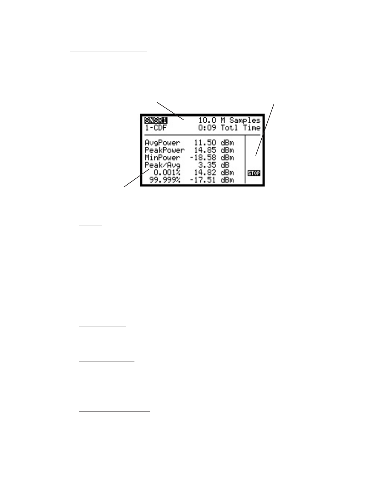
5.3.3 Statistical Mode. . . . . . . . . . . . . . . . . . . . . . . . . . . . . . . . . 5-4
5.3.4 Pulse Mode . . . . . . . . . . . . . . . . . . . . . . . . . . . . . . . . . . . . 5-5
5.4 Selecting the Right Measurement Mode . . . . . . . . . . . . . . . . . . . . . 5-6
5.4.1 CW Mode . . . . . . . . . . . . . . . . . . . . . . . . . . . . . . . . . . . . 5-6
5.4.2 Modulated Mode . . . . . . . . . . . . . . . . . . . . . . . . . . . . . . . 5-6
5.4.3 Pulse Mode . . . . . . . . . . . . . . . . . . . . . . . . . . . . . . . . . . . . 5-6
5.4.4 Statistical Mode. . . . . . . . . . . . . . . . . . . . . . . . . . . . . . . . . 5-7
. . . . . . . . . . . . . . . . . . . . . . . . . . . . . . . . . . .
Power Sensors . . . . . . . . . . . . . . . . . . . . . .
. . . .
Sensors . . . . . . . . . . . . . . . . . . . . . . . . . . . .
Sensors
Measurement Mode . . . . . . . . . . . . . . . . . . .
Mode . . . . . . . . . . . . . . . . . . . . . . . . . . . . .
. . . . . . . . . . . . . . . . . . . . . . . . . . . . . . . . . .
Mode. . . . . . . . . . . . . . . . . . . . . . . . . . . . . . .
5.5 Setting Measurement Parameters . . . . . . . . . . . . . . . . . . . . . . . . . . 5-7
5.5.1 What You Need to Know . . . . . . . . . . . . . . . . . . . . . . . . . 5-7
5.5.2 Channel Parameters Menu Settings . . . . . . . . . . . . . . . . . . 5-7
5.5.3 Trig/Time Menu Settings . . . . . . . . . . . . . . . . . . . . . . . . . . . 5-8
5.6 Settings for some Common Signal Types . . . . . . . . . . . . . . . . . . . . 5-9
5.6.1 Measuring GSM and EDGE . . . . . . . . . . . . . . . . . . . . . . . 5-9
5.6.2 Measuring NADC . . . . . . . . . . . . . . . . . . . . . . . . . . . . . . . 5-9
5.6.3 Measuring iDEN . . . . . . . . . . . . . . . . . . . . . . . . . . . . . . . . 5-10
5.6.4 Measuring Bluetooth . . . . . . . . . . . . . . . . . . . . . . . . . . . . . 5-11
5.6.5 Measuring CDMA. . . . . . . . . . . . . . . . . . . . . . . . . . . . . . . 5-12
5.6.6 Measuring HDTV . . . . . . . . . . . . . . . . . . . . . . . . . . . . . . . 5-13
5.7 Measurement Accuracy . . . . . . . . . . . . . . . . . . . . . . . . . . . . . . . . . 5-13
5.7.1 Error Contributions . . . . . . . . . . . . . . . . . . . . . . . . . . . . . . 5-14
5.7.2 Discussion of Error Terms . . . . . . . . . . . . . . . . . . . . . . . . . 5-14
5.7.3 Sample Uncertainty Calculations . . . . . . . . . . . . . . . . . . . . 5.17
Parameters . . . . . . . . . . . . . . . . . . . . . . . .
Need to Know
Menu Settings . . . . . . . . . . . . . . . .
v

Contents Boonton Electronics
4530 Series RF Power Meter
Contents (Cont)
CHAPTER/SECTION PAGE
APPENDIX A
Available Sensors . . . . . . . . . . . . . . . . . . . . . . . . . . . . . . . . . . . . . . . . . . A-1 . . . . . . . . . . . . . . . . . . . . . . . . . . . . . . . . . . . .
APPENDIX B
Model 2530 1 GHz Calibrator . . . . . . . . . . . . . . . . . . . . . . . . . . . . . . . . B-1
Accessories . . . . . . . . . . . . . . . . . . . . . . . . . . . . . . . . . . . . . . . . . . . . . B-1
Specification . . . . . . . . . . . . . . . . . . . . . . . . . . . . . . . . . . . . . . . . . . . . . B-1
vi

Boonton Electronics Contents
4530 Series RF Power Meter
List of Tables
TABLE PAGE
3-1 Keyboard Controls, Indicators and Connectors . . . . . . . . . . . . . . . . 3-2Indicators and Connectors . . . . . . . . . . . . . . .
3-2 4530 Graph and Text Mode Edit Menus . . . . . . . . . . . . . . . . . . . . . . 3-13
3-3 Measurement Pages . . . . . . . . . . . . . . . . . . . . . . . . . . . . . . . . . . . . . 3-14
3-4 Zero/Cal Menu. . . . . . . . . . . . . . . . . . . . . . . . . . . . . . . . . . . . . . . . . 3-20
3-5 Main Menu Summary . . . . . . . . . . . . . . . . . . . . . . . . . . . . . . . . . . . . 3-44
3-6 Graph/Text Header Error and Status Messages . . . . . . . . . . . . . . . . . 3-47
3-7 Sensor and Probe Error Messages . . . . . . . . . . . . . . . . . . . . . . . . . . 3-47
3-8 Sensor Zero / Cal Status Codes . . . . . . . . . . . . . . . . . . . . . . . . . . . . 3-48
3-9 Startup Error Messages . . . . . . . . . . . . . . . . . . . . . . . . . . . . . . . . . . 3-48
4-1 Remote Command Summary . . . . . . . . . . . . . . . . . . . . . . . . . . . . . . 4-56
4-2 Remote Interface Error Codes . . . . . . . . . . . . . . . . . . . . . . . . . . . . . 4-67
4-3 Measurement Result Status Codes . . . . . . . . . . . . . . . . . . . . . . . . . . 4-67
Mode Edit Menus . . . . . . . . . . . . . . . . . . . . .
. . . . . . . . . . . . . . . . . . . . . . . . . . . . . . . . . . . .
. . . . . . . . . . . . . . . . . . . . . . . . . . . . . . . . . . . . .
. . . . . . . . . . . . . . . . . . . . . . . . . . . . . . . . . . .
vii

Contents Boonton Electronics
4530 Series RF Power Meter
List of Illustrations
ILLUSTRATION PAGE
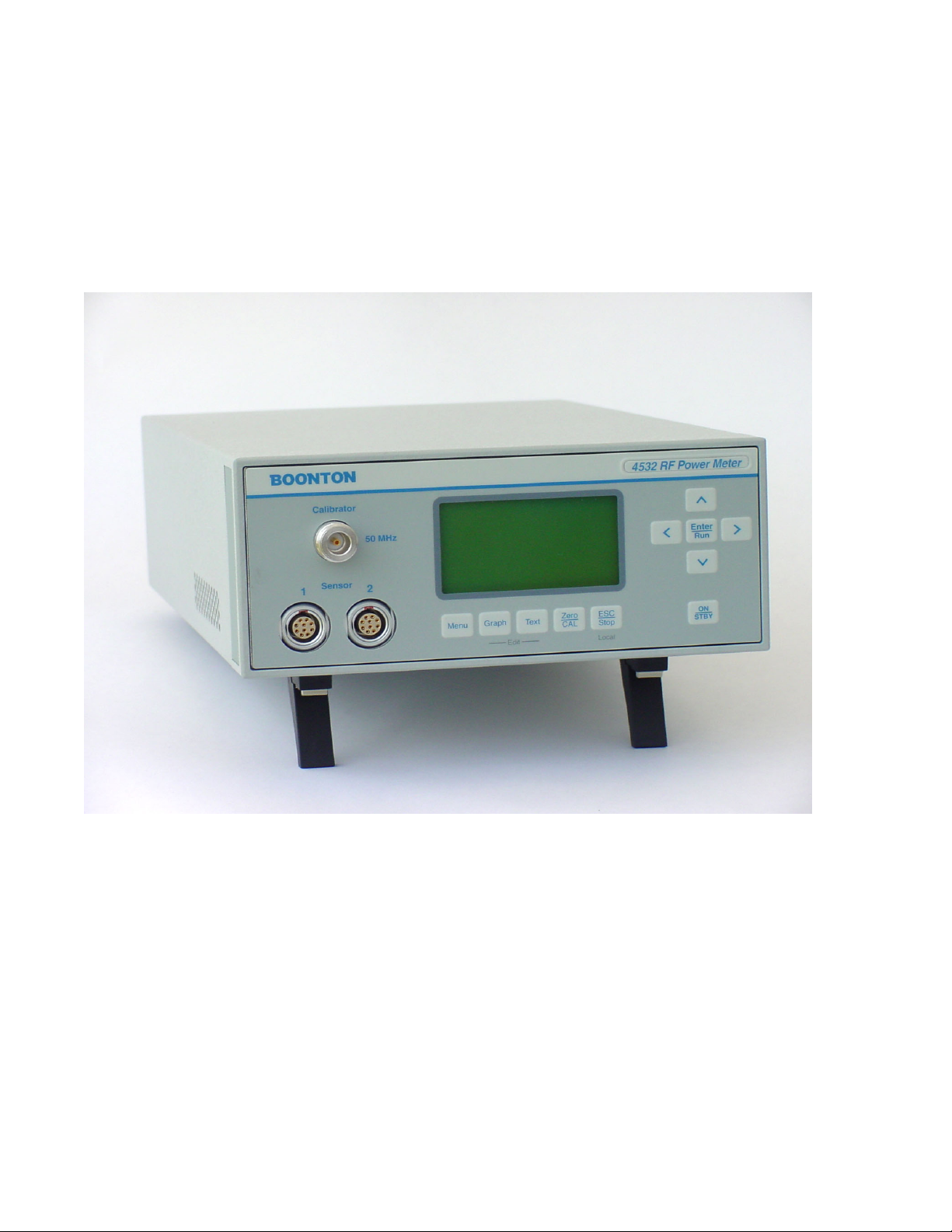
C-1 4530 Series RF Power Meter. . . . . . . . . . . . . . . . . . . . . . . . . . . . . . x
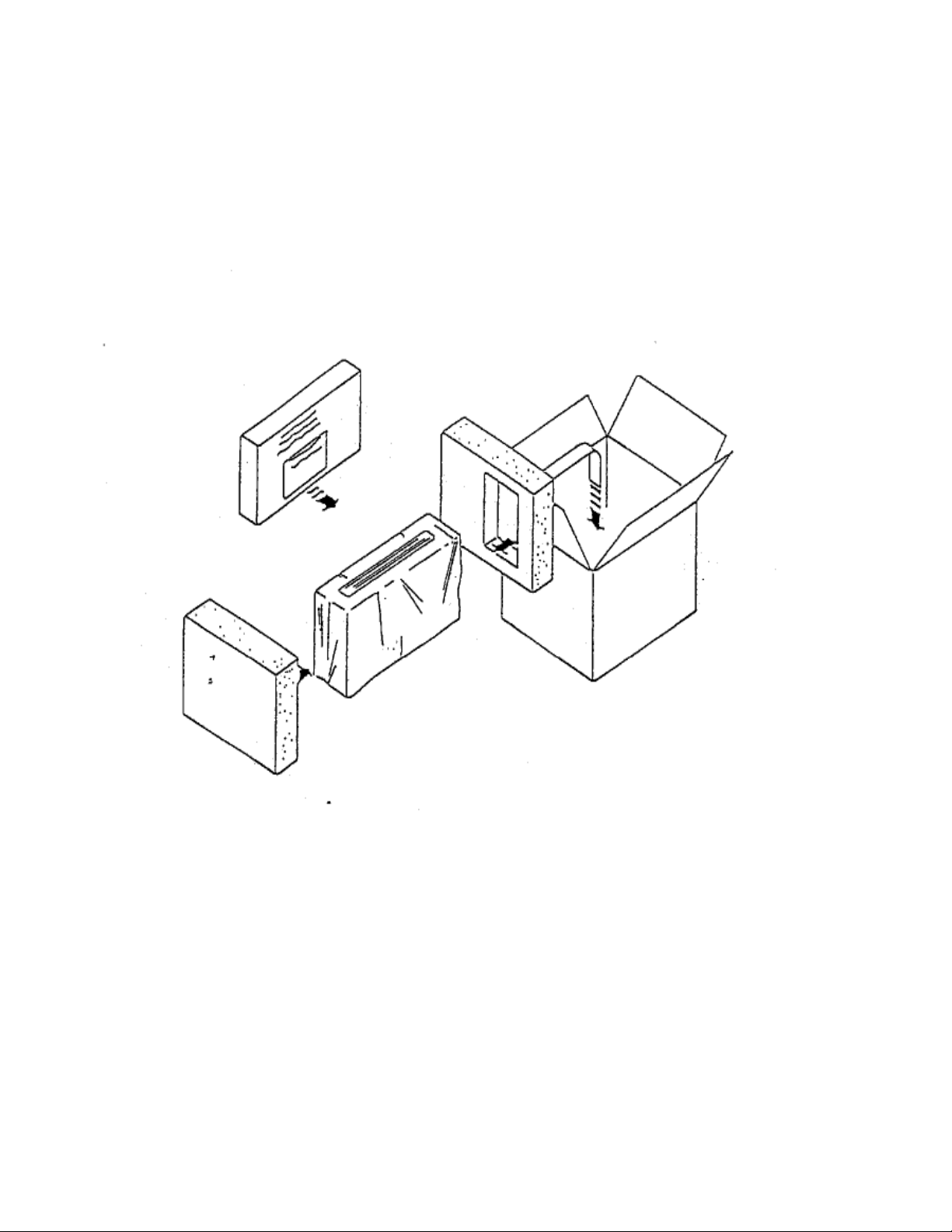
2-1 Unpacking and Packing . . . . . . . . . . . . . . . . . . . . . . . . . . . . . . . . . . 2-2
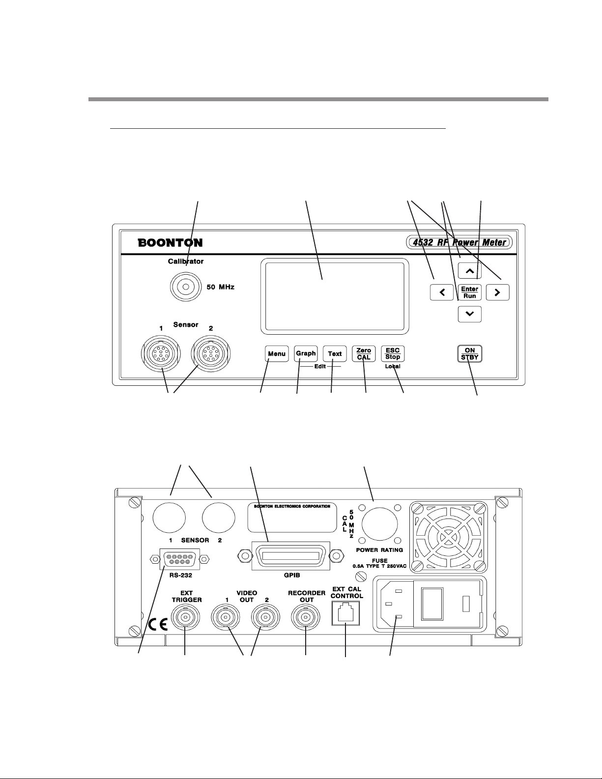
3-1 4530 Series, Front Panel . . . . . . . . . . . . . . . . . . . . . . . . . . . . . . . . . 3-1
3-2 4530 Series, Rear Panel . . . . . . . . . . . . . . . . . . . . . . . . . . . . . . . . . . 3-1
3-3 Display Areas. . . . . . . . . . . . . . . . . . . . . . . . . . . . . . . . . . . . . . . . . . 3-5
3-4 Menu Mode Display . . . . . . . . . . . . . . . . . . . . . . . . . . . . . . . . . . . . . 3-6
3-5 Text Mode Display . . . . . . . . . . . . . . . . . . . . . . . . . . . . . . . . . . . . . . 3-6
3-6 Graph Mode Display . . . . . . . . . . . . . . . . . . . . . . . . . . . . . . . . . . . . 3-7
3-7 Edit Mode Display . . . . . . . . . . . . . . . . . . . . . . . . . . . . . . . . . . . . . . 3-7
3-8 Zero/Cal Mode Display . . . . . . . . . . . . . . . . . . . . . . . . . . . . . . . . . . 3-8
3-9 Main Menu . . . . . . . . . . . . . . . . . . . . . . . . . . . . . . . . . . . . . . . . . . . . 3-8
3-10 Digit Editing Mode Display . . . . . . . . . . . . . . . . . . . . . . . . . . . . . . . . 3-9
3-11 Menu Mode Display. . . . . . . . . . . . . . . . . . . . . . . . . . . . . . . . . . . . . 3-9
3-12 Text Mode Display . . . . . . . . . . . . . . . . . . . . . . . . . . . . . . . . . . . . . . 3-10
3-13 Graph Mode Display . . . . . . . . . . . . . . . . . . . . . . . . . . . . . . . . . . . . 3-11
3-14 Edit Mode Display . . . . . . . . . . . . . . . . . . . . . . . . . . . . . . . . . . . . . . 3-13
3-15 Graphic Mixed Mode Measurement Displays . . . . . . . . . . . . . . . . . . 3-15
3-16 Graphic Mixed Mode Edit Displays . . . . . . . . . . . . . . . . . . . . . . . . . 3-15Edit Displays . . . . . . . . . . . . . . . . . . . . . . . .
3-17 Text Mixed Mode Measurement Displays . . . . . . . . . . . . . . . . . . . . . 3-16
Displays . . . . . . . . . . . . . . . . . . . .
3-18 Text Mixed Mode Edit Displays . . . . . . . . . . . . . . . . . . . . . . . . . . . . 3-16
3-19 External Calibrator Connection . . . . . . . . . . . . . . . . . . . . . . . . . . . . . 3-19
3-20 Zero/Calibration Menu . . . . . . . . . . . . . . . . . . . . . . . . . . . . . . . . . . . 3-19
Displays . . . . . . . . . . . . . . . . . . . . . . . . . . .
Connection . . . . . . . . . . . . . . . . . . . . . . . . . . . .
. . . . . . . . . . . . . . . . . . . . . . . . . . . . . . . . . .
viii

Boonton Electronics Contents
4530 Series RF Power Meter
SAFETY SUMMARY
The following general safety precautions must be observed during all phases of operation and maintenance of this
instrument. Failure to comply with these precautions or with specific warnings elsewhere in this manual violates safety
standards of design, manufacture, and intended use of the instrumenmts. Boonton Electronics Corporation assumes
no liability for the customer’s failure to comply with these requirements.
INSTRUMENT MUST BE GROUNDED
T o minimize shock hazard, the instrument chassis and cabinet must be connected to an electrical ground. The instrument is equipped with a three conductor, three prong AC power cable. The power cable must either be plugged into an
approved three-contact electrical outlet or used with a three-contact to a two-contact adapter with the (green) grounding wire firmly connected to an electrical ground at the power outlet.
DO NOT OPERA TE THE INSTRUMENT IN AN EXPLOSIVE A TMOSPHERE
Do not operate the instrument in the presence of flammable gases or fumes.
KEEP A WA Y FROM LIVE CIRCUITS
Operating personnel must not remove instrument covers. Component replacement and internal adjustments must be
made by qaulified maintenance personnel only. Never replace components or operate the instrument with the covers
removed and the power cable connected. Even with the power cable cable removed, dangerous voltages may be
present. Always remove all jewelry (rings, watches, etc.) and discharge circuits before touching them. Never attempt
internal service or adjustment unless another person, capable of rendering first aid and resusitaion, is present.
DO NOT SUBSTITUTE P ARTS OR MODIFY INSTRUMENT
Do not substitute parts or perform any unauthorized modification of the instrument. Return the instrument to
Boonton Electronics for repair to insure that the warrenty and safety features are maintained.
! This safety requirement symbol has been adopted by the International
Electrotechnical Commission. Document 66 (Central Office) 3, Paragraph
5.3, which directs that an instrument be so labeled if, for the correct use of
the instrument, it is necessary to refer to the instruction manual. In this
case it is recommended that reference be made to the instruction manual
when connecting the instrument to the proper power source. Verify that
the correct fuse is installed for the power available.
NOTE NOThe appearance of NOTE
CAUTION The CAUTION sign denotes a hazard. It calls attention to an operating
The appearance of TE indicates that clarifying information follows
immediately
immediately. In many cases this information is necessary for proper operation or is a further explanation of important data.
procedure which, if not correctly performed or adhered to, could result in
damage to the instrument or equipment under test. Do not procedeed
beyond a CAUTION sign until the indicated conditions are fully understood and met.
WARNING The WARNING sign denotes a hazard. It calls attention to an operating
procedure, which, if not correctly performed or adhered to could result in
personal injury. Do not procedeed beyond a WARNING sign until the
indicated conditions are fully understood and met.
ix
Contents Boonton Electronics
4530 Series RF Power Meter
Figure C-1 4530 Series RF Power Meter
x

Boonton Electronics Contents
4530 Series RF Power Meter
Repair Policy
Model 4531 / 4532 Instrument. If the Boonton Model 4531/4532 RF Power Meter is not operating correctly and
requires service, contact the Boonton Electronics Service Department for return authorization. You will be provided
with an RMA number and shipping instructions. Customers outside the USA should contact the authorized Boonton
distributor for your area. The entire instrument must be returned in its original packing container. If the original
container is not available, Boonton Electronics will ship a replacement container and you will be billed for the container
cost and shipping charges.
Boonton Peak Power Sensors. Damaged or defective peak power sensors are repaired as separate accessories.
Note that sensors which have failed due to overloading, improper mating, or connecting to an out-of-tolerance connector are not considered defective and will not be covered by the Boonton Warranty. If repair is needed, contact the
Boonton Electronics Service Department for return authorization. You will be provided with an RMA number and
shipping instructions. Customers outside the USA should contact the authorized Boonton distributor for your area.
Only the defective sensor should be returned to Boonton, not the entire instrument. The sensor must be returned in its
original packing container. If the original container is not available, Boonton Electronics will ship a replacement
container and you will be billed for the container cost and shipping charges. If a new sensor is ordered, note that it
does not include a sensor cable - this item must be ordered separately.
arranty
.
Contacting Boonton. Customers in the United States having questions or equipment problems may contact
Boonton Electronics directly during business hours (8 AM to 5 PM Eastern) by phoning (973) 386-9696. FAX messages may be sent at any time to (973) 386-9191. Email inquiries should be sent to service@boonton.com.
International customers should contact their authorized Boonton Electronics representative for assistance. A current
list of authorized US and international representatives is available on the Boonton website at www.boonton.com.
Limited W arranty
Boonton Electronics warrants its products to the original Purchaser to be free from defects in material and workmanship and to operate within applicable specifications for a period of one year from date of shipment for instruments,
probes, power sensors and accessories. Boonton Electronics further warrants that its instruments will perform within
all current specifications under normal use and service for one year from date of shipment. These warranties do not
cover active devices that have given normal service, sealed assemblies which have been opened, or any item which has
been repaired or altered without Boonton’s authorization.
Boonton’s warranties are limited to either the repair or replacement, at Boonton’s option, of any product found to be
defective under the terms of these warranties.
There will be no charge for parts and labor during the warranty period. The Purchaser shall prepay inbound shipping
charges to Boonton or its designated service facility and shall return the product in its original or an equivalent
shipping container. Boonton or its designated service facility shall pay shipping charges to return the product to the
Purchaser for domestic shipping addresses. For addresses outside the United States, the Purchaser is responsible for
prepaying
all shipping charges, duties and taxes (both inbound and outbound).
THE FOREGOING W ARRANTIES ARE IN LIEU OF ALL OTHER W ARRANTIES, EXPRESS OR IMPLIED, INCLUDING, BUT NOT LIMITED TO, THE IMPLIED W ARRANTIES OF MERCHANT ABILITY AND FITNESS FOR A P ARTICULAR PURPOSE. Boonton will not be liable for any incidental damages or for any consequential damages, as
defined in Section 2-715 of the Uniform Commercial Code, in connection with products covered by the foregoing
warranties.
xi

Contents Boonton Electronics
4530 Series RF Power Meter
xii

Boonton Electronics Chapter 1
4530 Series RF Power Meter General Information
1. GENERAL INFORMA TION
1.1 DESCRIPTION
The 4530 Series RF Power Meter is a new generation of instruments. It allows high-resolution power measurement of
a wide range of CW and modulated RF signals over a dynamic range of up to 90dB depending on sensor. The power
meter is available configured as the single-channel Model 4531, or as the dual-channel Model 4532. For the remainder
of this manual, the series designation of 4530 will be used to indicate either model, except when otherwise stated.
The 4530 is really several instruments in one, and can function as a CW Power Meter, a Peak Power Meter , a Statistical
Power Analyzer, and an RF Voltmeter. It accepts the full series of Boonton RF power and voltage sensors, which
includes coaxial dual-diode sensors and thermal sensors. Sensor data and calibration information is automatically
downloaded from the sensor or “smart adapter” whenever a new sensor is connected, eliminating the need to manually
enter calibration factors.
When used as a CW power meter, the 4530 provides seamless measurement performance due to the extremely wide
dynamic range of its input stage. Thermal and peak power sensors require no range switching under any conditions,
and even CW diode sensors spanning a 90dB dynamic range require only two widely overlapping ranges. This means
that practically any measurement can be performed without the interruptions and non-linearities associated with the
range changes of conventional power meters.
For modulated signals, the 4530 can make accurate average and peak power measurements with modulation bandwidths as high as 20MHz, making it ideal for high-speed digitally modulated carriers such as CDMA, W-CDMA, GSM,
TDMA, HDTV and UMT . Periodic and pulse waveforms can be displayed in graphical format, and a host of automatic
measurements are available which characterize the time and power profiles of the pulse. Effective sampling rates up to
50MSa/sec and user programmable cursors allow instantaneous power measurements at precise time delays from the
pulse edge or an external trigger as well as time gated or power gated peak and average power.
For spread-spectrum or randomly modulated signals such as CDMA, the 4530’s powerful statistical analysis mode
allows full profiling of the power probability at all signal levels. Sustained acquisition rates in excess of one million
readings per second along with rangeless operation insure that a representative population can be acquired and
analyzed in minimum time. By analyzing the probability of occurrence of power levels approaching the absolute peak
power, it is possible to characterize the occasional power peaks that result in amplifier compression and data errors.
Because of the random and very infrequent nature of these events, they are next to impossible to spot with the
conventional techniques used in other universal power meters. In addition, the instrument’s extremely wide video
bandwidth insures that even the fastest peaks will be accurately measured.
The 4530’s powerful dual-processor architecture permits advanced measurement capabilities with unprecedented
speed and performance. A high-speed, floating-point digital signal processor (DSP) performs the measurements. It
gathers and processes the power samples from the sensors, performs time-stamping, linearity correction, gain adjustment and filtering, all in fractions of a microsecond. The processed measurements are then passed to a dedicated,
32-bit I/O processor that monitors the keyboard, updates the LCD display and responds to RS-232 and GPIB requests
for formatted measurements. This design eliminates the speed tradeoffs between measurement data input (acquisition)
and output (over the GPIB) that are so common among other power meters.
, the 4530 provides seamless measurement performance due to the extremely wide
Instrument operating firmware is stored in flash memory that may be field reprogrammed with any PC via the onboard
RS-232 port. Free firmware upgrades permit the easy addition of new features or capabilities that may become available
in the future. Visit the Boonton website at WWW.BOONTON.COM for upgrade information and to download the
latest firmware version.
1-1

Chapter 1 Boonton Electronics
General Information 4530 Series RF Power Meter
1.2 FEATURES
Multi-mode capability Utilizes CW sensors, Peak Power sensors and V oltage probes with automatic sens-
ing and setup for each type. Measures conventional CW power and voltage,
power versus time for pulse analysis, and statistical power distributions for spread
spectrum signals.
Text and Graphics The backlit LCD display shows numerical results as well as graphical results for all
measurements. Measurements are displayed using a large, easy-to-read numerical
format, or in graph mode with a fast-updating, oscilloscope-like trace.
Dual Independent ChannelsDual Independent Channels Model 4532 is equipped with two identical independent measurement channels
with the capability to display two pulse measurements, two statistical measurements or two CW measurements at the same time.
Remote Programming All functions except power on/off can be controlled by a GPIB interface or via an
RS-232 serial connection. The programming language follows the SCPI model with
added non-SCPI commands for special applications.
1.3 ACCESSORIES
Supplied accessories: 1 – NEMA type power cable
1 – Fuse Kit
1 – 4530 Series Operators Instruction Manual
Other accessories: Rack Mounting Kit
See Boonton Electronics Power Sensor Manual for power sensors available.
Options: Model 4531 Single Channel RF Power Meter
Model 4532 Dual Channel RF Power Meter
Rear panel sensor inputs
Rear panel calibrator output
1.4 SPECIFICATIONS MODTIONS MODEL 4531 and 4532 4531 and 4532
1.4.1 General.
Sensor Inputs (Performance depends upon sensor model selected)
Channels: Single Input: Model 4531
Dual Input: Model 4532
RF Frequency Range: 10 kHz to 110 GHz ( Sensor dependent )
Peak Power Measurement Range: -40 to +20 dBm ( Sensor dependent )
CW Measurement Range: -70 to +44 dBm ( Sensor dependent )
Relative Offset Range: ±99.99 dB
V ideo Bandwidth: 20 MHz (Sensor dependent)
Single Shot Bandwidth: 250 kHz (based on 10 samples per pulse)
Pulse Repetition Rate: 1.8 MHz maximum for stable, internal trigger
1-2

Boonton Electronics Chapter 1
4530 Series RF Power Meter General Information
1.4.2 Calibration Sources
Internal Calibrator
Output Frequency: 50 MHz ± 0.005%
Level: -60 to +20 dBm
Resolution: 0.1 dB steps
Source SWR: 1.05 (reflection coefficient = 0.024)
Accuracy, 0° to 20°C, NIST traceable: At 0 dBm: ±0.055 dB (1.27%)
+20 to -39 dBm: ±0.075 dB (1.74%)
-40 to -60 dBm: ±0.105 dB (2.45%)
RF Connector: T ype N
External Calibrator (See Appendix B)
Model 2530 1 GHz Calibrator (Purchased separately if required)
1.4.3 T rigger ( Peak power modes only . )
Modes: Pre-trigger and post-trigger
Trigger Time Resolution: 20 ns
Trigger Delay: ±900µs for timespans 5µs and faster
±4ms for timespans 10µs to 50µs
± (80 x TimeSpan) for timespans 50µs to 2ms
± (30 x TimeSpan) for timespans 5ms and slower
Trigger Holdoff: 0 µs to 1 sec, resolution 1µs
Internal Trigger Range: Equivalent to -30 to +20 dBm pulse amplitude range.
External Trigger Range: ±5 volts, ±50 volts with 10:1 divider probe.
External Trigger Input: 1 megohm in parallel with approximately 15pF , dc coupled.
External Trigger Connector: Rear-panel BNC input
1.4.4 Sampling Characteristics
Effective sampling rate: 50 Megasamples per second (each channel, pulse mode)
Sustained sampling rate: 2.5 Megasamples per second (each channel, pulse mode)
Measurement Technique: Continuous and triggered (burst) sampling
1-3

Chapter 1 Boonton Electronics
General Information 4530 Series RF Power Meter
1.4.5 Measurement Characteristics
Measurements: Average Power*
Maximum A verage Power*
Minimum A verage Power*
Maximum Instantaneous (“Peak”) Power*
Minimum Instantaneous Power*
Peak to A verage Power Ratio*
Cumulative Distribution Functions: CDF , 1- CDF ,
Probability Distribution (histogram)
Power at a percent statistical probability
Statistical probability at a power level
CW Power
RF V oltage
* All measurements marked with an asterisk (*) may be performed con-
tinuously, or in a synchronous, triggered mode. When triggered, these
measurements may be made at a single time offset relative to the trigger ,
or over a defined time interval. The time offset or interval may be before
or after, or may span the trigger interval.
Channel Math: Displays the ratio, sum (power sensors) or difference (voltage sensors)
between channels or between a channel and a reference measurement
(Modulated and CW modes only).
Trace A veraging: 1 to 4096 samples per data point.
Panel setup storage: 4 complete setups.
Measurement rate (via GPIB): Greater than 200 two-channel measurements per second, neglecting bus
master overhead, or 500 single-channel measurements per sec.
1.4.6 Sensor Characteristics
CW Power Sensors
Power Detection Technique: Dual diode, single diode or thermo-electric.
Internal Data: Frequency and linearity calibration tables, frequency range, power range,
sensor type, serial number and other sensor dependent information are
stored in EEPROM within the sensor cable or in a cable-adapter for use
with existing CW sensors.
Peak Power Sensors
Power Detection Technique: Dual diode with selectable detector bandwidth.
Signal compression: The use of logarithmic signal compression circuitry in the sensor enables
the instrument to measure and analyze changes in power exceeding 60
dB in a single range.
Internal Data: Frequency, linearity and temperature calibration tables, frequency range,
power range, sensor type, serial number and other sensor dependent
information are stored in EEPROM within the peak power sensor.
Sensor Cable: The sensor cable is detachable from both sensor and instrument. The
standard cable length is 5 feet. Optional cable lengths are 10, 20, 25, and
50 feet. Additional cable length will affect measurement bandwidth.
RF V oltage Sensors Dual diode detector.
1-4

Boonton Electronics Chapter 1
4530 Series RF Power Meter General Information
1.4.7 Interface
Video Output: Compressed representation of detected RF envelope of peak channel(s)
envelope for external oscilloscope monitor or external device synchronization. This output is roughly logarithmic with input power, is not
calibrated, and can not be used for making any measurements.
Recorder Output: Programmable voltage output which may be used for monitoring mea-
surements or status of either channel, or for outputting a fixed,
programmable voltage. When used as a measurement monitor, the output is proportial to displayed signal level with programmable or automatic
scaling.
Output range: 0 to 10V (unipolar), or -10V to +10V (bipolar)
Output resolution: 5.0mV
Output impedance: 9 K
Absolute accuracy: ±100mV typical, ±200mV max, uncalibrated
±20mV after user calibration
Linearity: 0.1% typical
GPIB Interface: Complies with IEEE-488.1. Implements AH1, SH1,T6, LE0, SR1, RL1, PP0,
DC1, DT1, C0, and E1.
RS-232 Interface: Accepts GPIB commands (except bus dependent commands). Provides
for user software updates.
Remote Programming: SCPI (1990) compliant and Native Mode commands via GPIB or RS-232
interfaces.
Software Drivers: LABVIEW drivers available.
1.4.8 Environmental Specifications
General: Manufactured to the intent of MIL-T 28800E, T ype III, Class 5, Style E
CE Mark: Conforms to EU specifications:
EN 61010-1(90)(+A1/92)(+A2/95)
EN 61010-2-031
EN 61326-1(97)
EN 55022(94)(A2/97)Class B
Display: Graphic type LCD, with LED backlight. T ext and trace displays.
Operating Temperature: 0 to 5 0° C
Ventilation: Fan cooledFan cooled
Altitude: Operation up to 15,000 feet.
Storage Temperature: -40 to 75° C
Humidity: 95% ±5% maximum (non-condensing).
Operation up to 15,000 feet.
-40 to 75° C
95% ±5% maximum (non-condensing).
Shock: Withstands ±20G, 42ms impulse in X, Y , and Z axes, as per MIL-STD-810.
V ibration: Conforms to MIL-STD-167-1.
Power Requirements: 90 to 260 V AC, 47 to 63 Hz, <50 VA , <30 Watts. No voltage switching
Battery: One Lithium coin cell for maintaining non-volatile memory information.
Withstands ±20G, 42ms impulse in X, Y ,
Conforms to MIL-STD-167-1.
90 to 260 V AC, 47 to 63 Hz, <50 VA
required.
Not user replaceable. Typical battery life: 10 years.
1-5

Chapter 1 Boonton Electronics
General Information 4530 Series RF Power Meter
1.4.9 Physical Specifications
Dimensions: 3.5 inches (8.9 cm) high,
8.4 inches (21.3 cm) wide,
13.5 inches (34.3 cm) deep,
All dimensions are approximate, and exclude clearance for feet and
connectors. Feet may be removed for rack mounting.
Weight: 7 lbs. (3.2kg)
Connector location option: Sensor input(s) and calibrator connector: Front or rear panel.
Construction: Surface mount, multilayer printed circuit boards mounted to rigid alumi-
num frame and front extrusion/casting with aluminum sheet metal
enclosure.
Note: All specifications are subject to change without notice.
1-6

Boonton Electronics Chapter 2
4530 Series RF Power Meter Installation
2. INSTALLATION
2.1 UNPACKING & REPACKING
The 4530 Series RF Power Meter is shipped complete and ready to use upon receipt. Figure 2-1 shows the packaging
material. Save the packing material and container to ship the instrument if necessary . If the original materials are not
available, contact Boonton Electronics to purchase replacements. Store materials in a dry environment.
2.2 POWER REQUIREMENTS
The 4530 Series is equipped with a switching power supply that permits operation from a 90 to 260 volt, 47 to 63 Hz,
single-phase AC power source. Power consumption is 50 VA maximum. For replacement fuses, use the fuse kit
supplied.
CAUTION
Before connecting the instrument to the power source, make certain that the correct
fuse(s) are installed in the power entry module on the rear panel.
W ARNING
Before removing the instrument cover for any reason, place the entry module power
switch in the OFF (0=Off) position and remove the line cord from the entry module.
2.3 INTERNAL BA TTERY
The 4530 Series contains a coin cell Lithium battery to provide memory backup when the power source is off. The
battery has an expected life of ten years and is not user replaceable.
2.4 PRELIMINARY CHECK
The following preliminary check verifies that the instrument is operational and has the correct software installed. It
should be performed before the instrument is placed into service. T o perform the preliminary check, proceed as follows:
1. Connect the AC power cord to a suitable AC power source.
2. Press the upper half of the rocker type power switch located in the power entry module on the rear panel.
3. If the instrument does not start up, press the ON/STBY key on the front panel.
4. A banner message should appear on the LCD display, followed by a self-check display and sensor detection
messages. If any fatal errors occur during the startup, the process will terminate with a failure message on the
display. Any marginal conditions detected will be indicated with a cautionary message, but the startup process
will be allowed to proceed.
5 . When the startup process is complete, press the Menu key twice to force the Main Menu to be displayed. Using
the arrow keys to move through the list of menu items and the Enter key to select Utilities > Sys-Tests >
SystemInf display. Verify that the Serial Number matches the number on the rear panel tag. If the numbers do not
match, contact Boonton Electronics technical support.
2-1
Chapter 2 Boonton Electronics
Installation 4530 Series RF Power Meter
6. The sensors supplied with the instrument may vary widely in model number and type. Refer to Section 3-9 for
information on connecting and calibrating sensors.
7. Upon successful calibration of the supplied sensors, the instrument is ready for use.
Figure 2-1. Packing and Unpacking Diagram
2-2
Boonton Electronics Chapter 3
4530 Series RF Power Meter Operation
3. OPERATION
3.1 OPERATING CONTROLS, INDICA TORS AND CONNECTIONS
Controls, indicators and connectors for the 4530 Series RF Power Meter are shown in figures 3-1 and 3-2. The front
panel is illustrated in figure 3-1 and the rear panel in figure 3-2.
12345
12 11 10 9 8 7 6
Figure 3-1. 4530 Series, Front Panel
12 13 1
18 17 16 15 14 19
Figure 3-2. 4530 Series, Rear Panel
3-1

Chapter 3 Boonton Electronics
Operation 4530 Series RF Power Meter
3.2 KEY FUNCTION SUMMARY
Table 3-1 references each operating key or connector to a callout in Figure 3-1or 3-2 and briefly describes the key
function
Table 3-1. Keyboard Controls and Connectors
Item Figure 3-1 Function
50 MHz Calibrator 1 The output of the built-in 50MHz programmable calibrator is available
from a Type-N connector located on the front or optionally on the rear
panel of the instrument. This calibrator is used to automatically calibrate
sensor offset and linearity, and can also be used as a general purpose
calibration signal source.
Display 2 The 4530 Series RF Power Meter uses a 160x80 pixel graphic liquid crystal
display module with a switchable LED backlight. The display contrast
may be adjusted by holding down the ESC key while pressing the
keys.
∧∧
∧
or
∧∧
∨∨
∨
∨
∨
< and > Keys 3 Used to navigate between levels of the menu structure while in Menu
Mode or Zero/Cal Mode and to select individual editing numeric parameters. In Text Mode and Graph mode these keys can be used to switch
the display between channels. In T ext or Graph Edit Modes, the < and >
keys scroll the header line left or right through a list of editable parameters.
∧∧
∨∨
and ∨ Keys 4 Used to scroll up and down through a list of items when in Menu Mode
∧
∨
∧
∧
∨
or Zero/Cal Mode. They are also used to increment and decrement parameter values or individual digits when editing. In certain Text Modes,
these keys can be used to page up or down through a series of measurement screens.
∧∧
(Key Repeat) -- - Note - If the ∧ or ∨ key is pressed and held when incrementing or
decrementing a variable, it enters auto-repeat mode. At first, there is a
short delay, and then the number begins to increment at a slow rate. The
increment rate accelerates to a medium rate after 2 seconds, and to a high
rate after 7 seconds. To select and hold the medium repeat rate, doubleclick the key - releasing and immediately pressing the key will inhibit the
high-speed auto-repeat rate so the value doesn’t “run away” just as the
desired number is being approached.
Enter/Run Key 5 Activates a menu selection or completes update of a parameter in Menu
Mode or Zero/Cal Mode. Pressing Enter/Run while stopped in Text
Mode or Graph Mode will start (or restart) the measurement process.
∨∨
∧
∨
∧
∨
ON/STBY Key 6 Switches the power meter between on and standby modes. When in
standby, some circuitry remains powered to reduce drain on the battery
used to maintain the non-volatile memory.
3-2

Boonton Electronics Chapter 3
4530 Series RF Power Meter Operation
Table 3-1. Keyboard Controls and Connectors (Cont)
Item Figure 3-1 Function
ESC/Stop K ey 7 Aborts any operation in progress when in Menu Mode or Zero/Cal Mode.
Pressing ESC/Stop while running in T ext Mode or Graph Mode first causes
the measurement process to stop. Pressing it when already stopped will
clear the screen and reset all measurement values. Pressing ESC/Stop
when the instrument is in remote mode (the GPIB has control of the
instrument and keyboard entry is disabled) will return it to local mode
(the instrument is under keyboard control) unless the local lockout command, LLO, has been issued by the controller.
Zero/CAL Key 8 Places the instrument in Sensor Zero/Calibration Mode and displays a
menu to allow automatic sensor offset and gain adjustments using the
built-in 50MHz calibrator or an external calibrator.
Text K ey 9 Places the instrument in Text Mode to display the current measurements
in a numeric format. Pressing Text while already in T ext Mode toggles the
top portion of the display between the normal T ext Mode header and Edit
Mode for each active channel.
Graph K ey 1 0 Places the instrument in Graph Mode to display the current measurement
waveforms in a graphical format. Pressing Graph while already in Graph
Mode toggles the top portion (header) of the display between the normal
Graph Mode header and Edit Mode for the active channel.
Menu Key 11 Places the instrument in Menu Mode to allow navigation of the menu
structure. Pressing Menu while already in Menu Mode returns the user
to the top-level Main Menu.
Sensor 1 - 2 12 One or two sensor inputs are located on the front, or optionally on the
rear panel of the instrument. These are 10-pin precision connectors designed to accept only Boonton Peak or CW power sensors and Boonton
voltage sensors. The sensor inputs are not measurement terminals and
cannot be used for other than the intended purpose.
CAUTION
Do not attempt to connect anything other than a
Boonton sensor or sensor adapter to the Sensor inputs!
GPIB 13 A rear-panel 24-pin GPIB (IEEE-488) connector is available for connect-
ing the power meter to the remote control General Purpose Instrument
Bus. GPIB parameters can be configured through the menu.
3-3
Chapter 3 Boonton Electronics
Operation 4530 Series RF Power Meter
Table 3-1. Keyboard Controls and Connectors (Cont)
Item Figure 3-1 Function
EXT CAL CONTROL 14 An RJ-11 type modular telephone jack is used to connect the instrument
to a Boonton Model 2530 1GHz Programmable Calibrator. This feature
must be used to calibrate peak power sensors that cannot be calibrated at
50MHz, the operating frequency of the built-in calibrator.
CAUTION
Do not attempt to connect the External Calibrator
Control RJ-11 port to a telephone line or to any device
other than a Boonton Model 2530, 1 GHz Calibrator!
RECORDER OUT 15 A rear-panel BNC programmable analog output is available for connec-
tion to an external chart recorder or other device. The output voltage
range is unipolar or bipolar 10 volts, and a 9K output impedance allows
for simple scaling using a single external load resistor. The output can be
programmed to produce a voltage proportional to signal level, or a logiclevel status voltage for signaling when the RF power is above or below
preset “alarm limit” thresholds. Recorder output parameters can be configured through the menu.
VIDEO OUT 1-2 1 6 Two rear-panel video BNC outputs are used to view the demodulated RF
envelope for each channel on an external oscilloscope when using peak
sensors. The output voltage is 0 to 2.5 volts, and is approximately proportional to the logarithm of the sensor power. These outputs are
uncalibrated, and should not be used for making any type of external
measurement.
EXT TRIGGER 17 A rear-panel BNC input is available for connecting an external trigger
source to the power meter. The input impedance is 1 megohm to allow
triggering from a common 10x oscilloscope probe, and the input voltage
range is +5 to -5 volts to simplify triggering from logic-level signals.
RS-232 18 A rear-panel 9-pin female “D” connector is used to connect the instru-
ment to a PC or other serial device. The power meter will directly interface
with most PC serial ports
RS-232 parameters can be configured through the menu.
AC Line Input 19 A multi-function power input module (lower right of rear panel) is used to
house the AC line input, main power switch, and safety fuse. The module
accepts a standard AC line cord, included with the power meter. The
power switch is used to shut off main instrument power . The safety fuse
may also be accessed once the line cord is removed. The instrument’s
power supply accepts 90 to 260VAC, so no line voltage selection switch
is necessary.
using a straight-through type RS-232 cable.
CAUTION
Replace fuse only with specified type and rating!
3-4
Boonton Electronics Chapter 3
4530 Series RF Power Meter Operation
3.3 DISPLAY FUNCTIONS
The screen display of the 4530 is divided into three sections: the header, the measurement window and the status
window. Because these functions apply to all modes of operation, it is very important to understand them thoroughly.
∧∧
∨∨
∧
Note that the display contrast may be adjusted by holding down the ESC key while pressing the
Header Status Window
∧
∧
∨ or ∨ keys.
∨
Measurement Window
Figure 3-3. Display Functions
3.3.1
Header. The header appears at the top of the screen. It displays a title line and a line of text describing the
status of the currently highlighted item (sensor status, measurement status or auxiliary measurement values).
If the item is a submenu, a short description of the menu’s function will appear . If it is a parameter , the present
value for that parameter is shown. If it is an action item, the action will be described, and upon activation, the
message will change to indicate that the action has occurred. The header is also used as a two-line parameter
editing window when in the Edit mode.
3.3.2 Measurement Window. The major portion of the screen displays the current measurement results in a single
(4531) or split-channel (4532) format. The text display shows a trace for the primary measurement of the
channel(s) (usually average power), which updates as samples are acquired. In addition, while in the text mode,
the channel source (sensor, reference, or math function) is displayed along with measurement units. While in
the Graph mode, at slower display timebases, the trace will roll from right to left in chart recorder format, while
faster timebases use an oscilloscope-like sweep.
3.3.3 Status Window. The right-hand portion of the screen displays six annunciators that indicate status for the
GPIB, calibrator and measurement. The first four indicate GPIB status: REM, TLK, LSN, and SRQ. Position five
is a measurement status indicator, that can display: STOP, RUN, AUTO, ARMD, or SNGL. Position six displays
CAL when the calibrator output is active.
3.3.4 Channel Selection. Pressing the < or > keys while in text or graph mode toggles the measurement window
between channels. If Channel 1 is active, pressing < from a split-channel display will display only Channel 1,
and pressing > at that point returns to the split channel display. Similarly, pressing > from the split-channel
screen switches to the Channel 2 only display and < returns to the split-channel format. Note that in the singlechannel Model 4531, there is no “Channel 2 only” display , and while the split-channel display is present, there
are no measurements for Channel 2.
3.3.5 Header / Page Selection. Pressing the
a series of three “measurement pages”, each displaying a different set of measurements or status indicators. In
single-channel text mode, the entire measurement window may change, while in graph mode or split-channel
format, only the “auxiliary” measurements shown in the header will change.
∧∧
∨∨
∧
∨ and ∨ Keys while in text or graph mode scrolls the display through
∧∧
∨
3-5

Chapter 3 Boonton Electronics
Operation 4530 Series RF Power Meter
3.4 OPERATING MODE SUMMARY
The 4530 can operate in several modes. It is possible to move between these modes without interrupting the measurements currently being performed, even though the measurement display may not always be present.
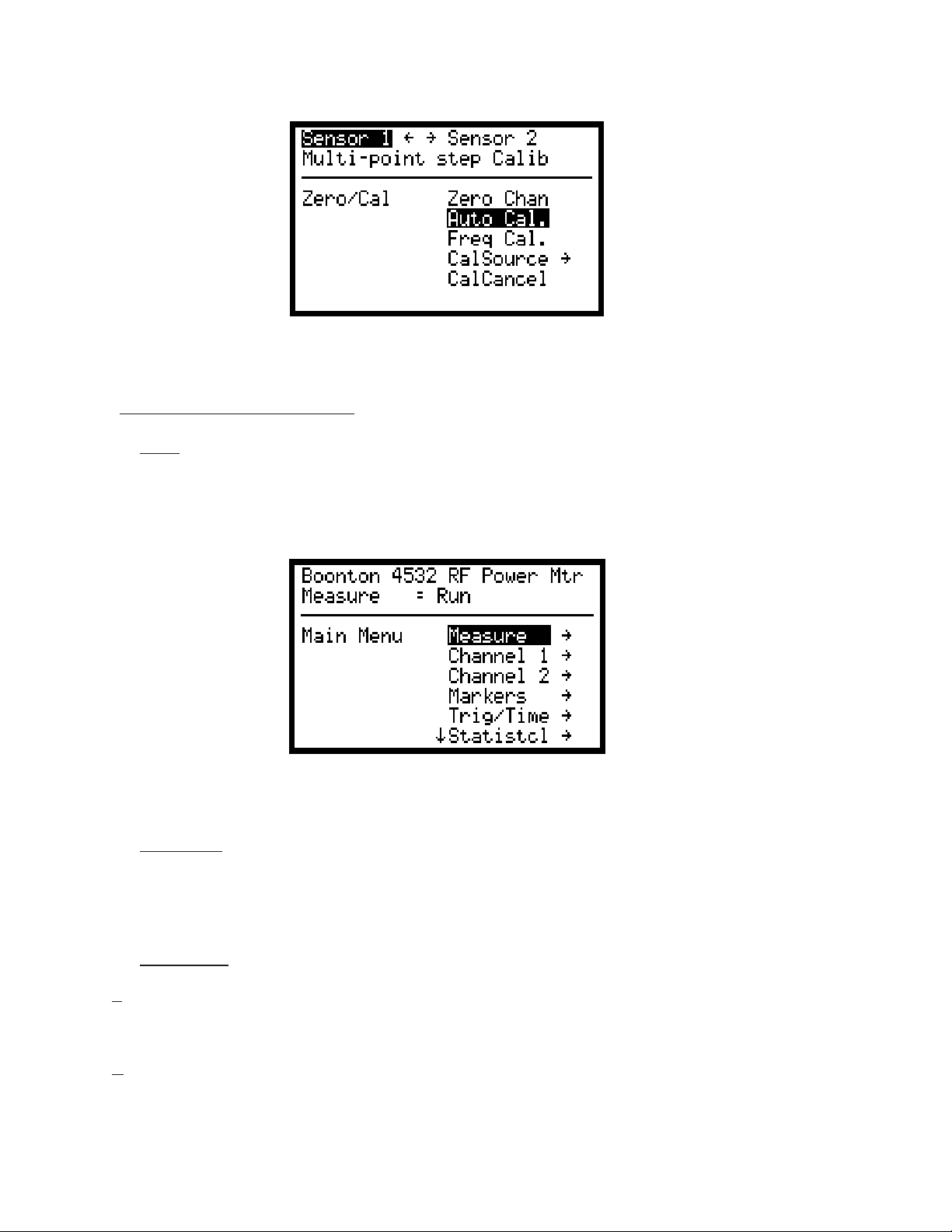
3.4.1 Menu Mode. The Menu Mode and is used to set operating parameters and start or stop measurements. A
series of displayed menus may be navigated using the front-panel arrow keys to access any instrument
function. The menu is an inverted tree, which begins at the top-level Main Menu, and branches downwards
through several levels of menu items and submenus. Refer to Table 3-5 for a summary of the instrument’s
entire menu structure. The first time the Menu key is pressed after power-up, the instrument enters the Menu
Mode and displays the Main Menu. Subsequent entries into Menu Mode will return the user to the same
position in the menu tree that was last used. Pressing the Menu key twice (or pressing it at any time when
already in Menu Mode) will always return to the Main Menu.
Figure 3-4. Menu Mode
3.4.2 Text Mode. In T ext Mode, the measurements are presented in a numerical format. A summary split-channel
(4532) display which shows the key measurement values for each channel in a large font may be selected, or
detailed single-channel (4531) display that presents a number of different measurements in a tabular format.
In the dual-channel text display, a programmable bargraph can be displayed to aid in viewing fluctuating
signals.
Dual Channel (Example) Single Channel (Example)
Figure 3-5. Text Mode
3-6
Boonton Electronics Chapter 3
4530 Series RF Power Meter Operation
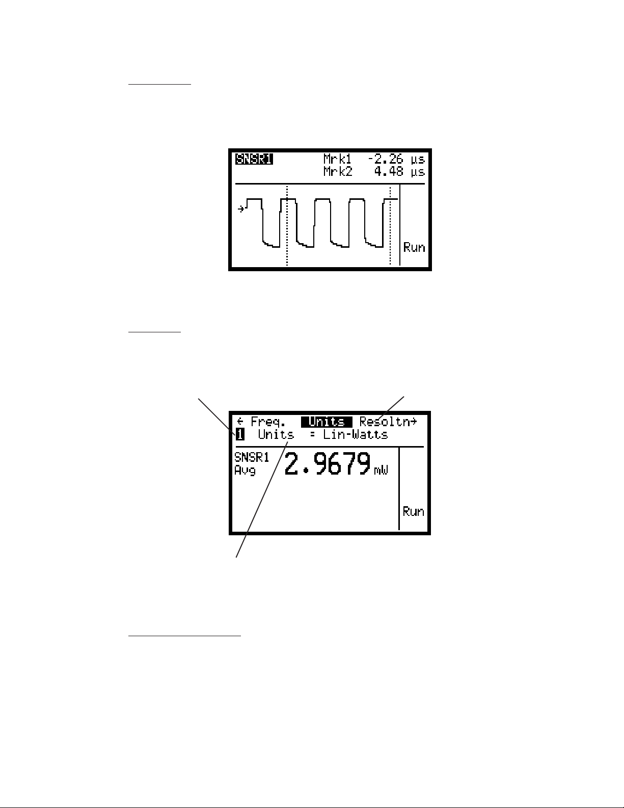
3.4.3 Graph Mode. The Graph Mode can present an oscilloscope style trace of power versus time or power
versus percent probability in statistical mode. Each channel may be viewed individually, or both can be
overlaid to make channel-to-channel comparisons. User programmable cursors can be moved back and forth
or up and down on the trace to define measurement regions of interest.
Figure 3-6. Graph Mode (Example)
3.4.4
Edit Mode. Edit Mode is an extension of the basic Graph Mode or Text Mode operation. The screen’s
measurement window continues to display and update the active measurement, but the two-line header area
at the top of the screen is used as an edit window. The arrow keys scroll through a list of commonly accessed
parameters, and allow these parameters to be updated “on the fly” without the need to return to Menu Mode.
Channel Edit Parameter List
Selected Parameter and current V alue
Figure 3-7. Edit Mode (Example)
3.4.5
Zero/Calibration Mode. When the 4530 is placed in Zero/Calibration Mode, a special menu is displayed
that allows quick, single-key access to the instrument’s sensor zeroing and linearity calibration functions. A
configuration submenu is available for each channel to set up certain calibration parameters.
3-7
Chapter 3 Boonton Electronics
Operation 4530 Series RF Power Meter
Figure 3-8. Zero/Cal Mode (Example)
3.5 MENU MODE OPERA TION
3.5.1
Entry. When the Menu key is pressed, the instrument enters Menu Mode (See Figure 3-9). The first time the
Menu key is pressed after power-up, the instrument will always enter Menu Mode displaying the Main Menu.
Subsequent entries into Menu Mode will return the user to the same position in the menu tree that was last
used.
Figure 3-9. Main Menu Screen
3.5.2 Navigation. The menu tree is navigated using the arrow keys until the desired menu is highlighted, and then
∧∧
that item may be activated. The
menu’s item list. Pressing > or Enter/Run will activate the highlighted item and move to a subordinate menu
item associated with the selected item. Pressing < or ESC will return to the parent menu. Pressing Graph, Text
or Zero/Cal will exit Menu mode and abort any parameter editing in progress.
∨ ∨
∧
∨ and ∨ keys are used to move the cursor up and down through the current
∧∧
∨
3.5.3 Menu Items. Menu items may be one of four types: Submenu, Numerical Value, Picklist, or Action.
a. Submenus. A submenu is simply a menu at a lower level containing more items. Activating a submenu item
will cause the current menu to become the parent menu, and the submenu will then be opened and become the
current menu.
b. Numerical Values. A numerical value is an operating parameter that can be edited. When a numerical value
item is activated, that item name (parameter) is displayed along with the highlighted current value of the
parameter. Editing is performed with the arrow keys. The default edit mode is increment/decrement mode.
∧∧
∨∨
∧
Only the
∨ and ∨ keys are used to increment or decrement the parameter’s value by a preset amount.
∧
∨
∧
3-8
 Loading...