

Page 1

2011-12 Ski-Doo 800 R E-Tec
Turbo Kit Installaon Instrucons
The BoonDocker E-Tec turbo is a Race Gas only kit at this me. We recommend a minimum of 100 octane
non-ethanol fuel or higher depending on boost levels and elevaon.
Addional informaon and updates on BoonDocker products may be available on the following sites.
• www.boondockers.com
• www.youtube.com/boondockerusa
• www.facebook.com/boondockerperformance
BoonDocker tollfree: 877-522-7805 local: 208-542-4411 fax: 208-524-7381 www.boondockers.com 1
Page 2
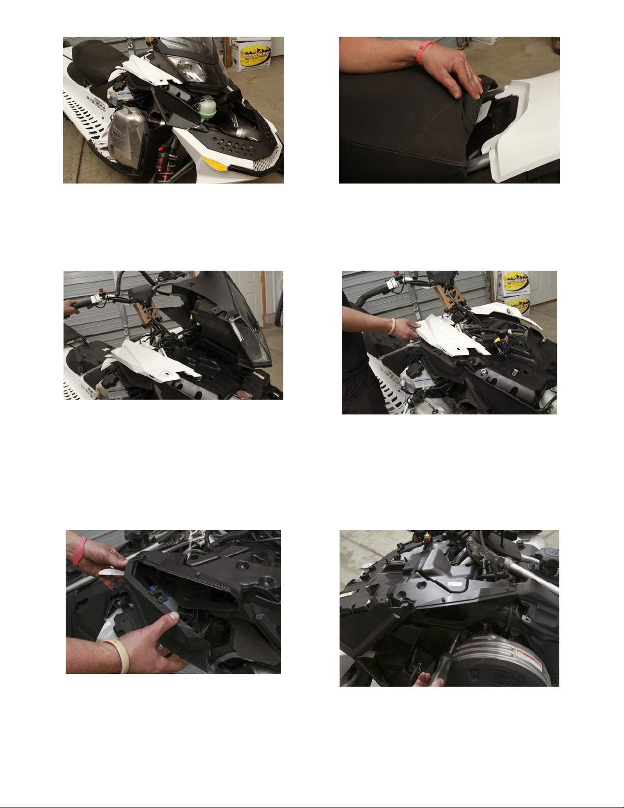
1. Remove both side panels and hood.
2. Remove the seat by liing up on the white plasc lever under the front and pulling the seat rearward.
3. Remove the torx bolts holding on the headlight /
gauge cluster. Disconnect the wiring harnesses hooked
to the headlights and gauge. Remove headlight and
gauge cluster.
5. Remove air intake screens from each side of the air
box plenum. Be careful to not damage the clips when
removing.
4. Remove the torx bolts holding the tank cowl to the air
box plenum, remove the gas cap nut, remove gas cap
and remove tank cowl.
6. Remove the hose clamp holding the air box plenum
to the intake ute.
BoonDocker tollfree: 877-522-7805 local: 208-542-4411 fax: 208-524-7381 www.boondockers.com 2
Page 3
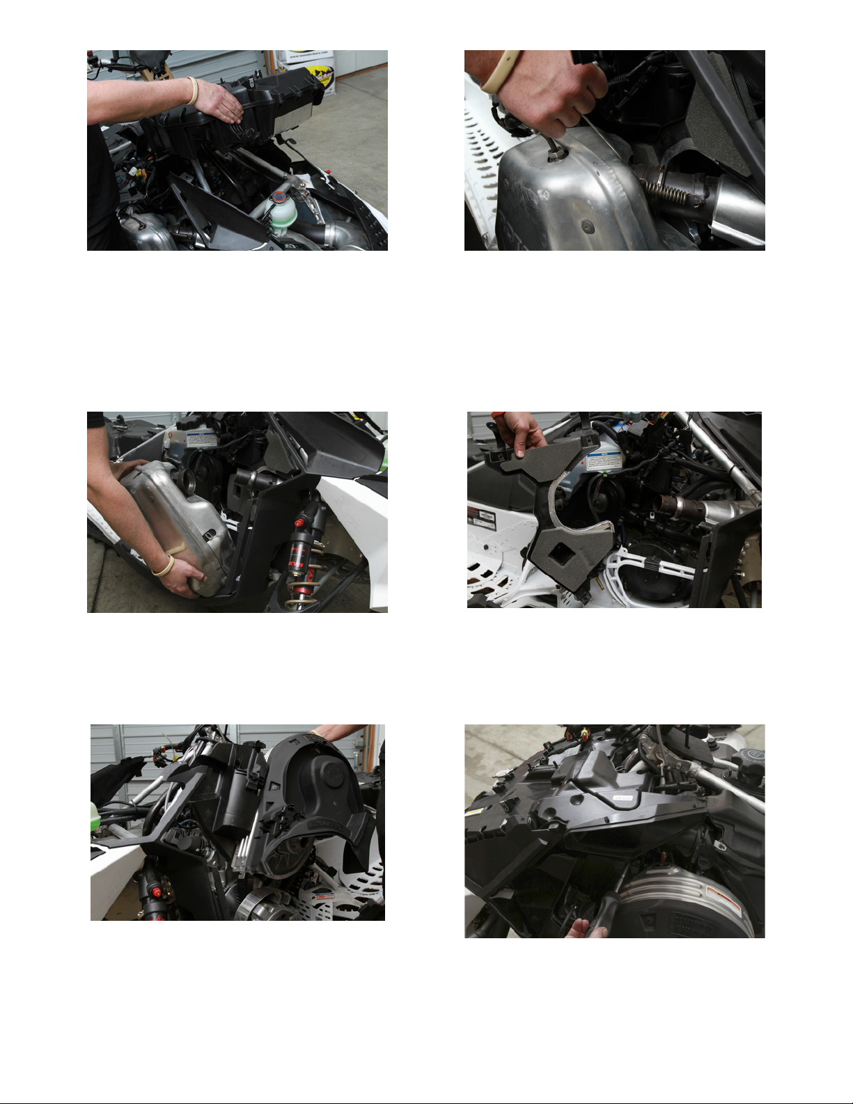
7. Remove coolant bole from airbox plenum, remove
velcro holding plenum to the chassis and remove the
air box plenum from the machine.
8. Using a spring puller remove the two springs holding
the silencer to the expansion chamber and the two
springs holding the silencer to the chassis.
9. Remove the exhaust temp sensor from the top of the
silencer and remove the silencer from the chassis.
11. Remove belt gaurd. 12. Disconnect sensor and twist the intake ute to re-
BoonDocker tollfree: 877-522-7805 local: 208-542-4411 fax: 208-524-7381 www.boondockers.com 3
10. Remove the exhaust noise shield.
move.
Page 4

13. Remove air box by sliding it vercally o the throle
body adaptor plate.
14. Remove clamps and remove throle body adaptor
plate from the throle bodies.
15. Remove the throle bodies and reed cages. Install
the included half reeds on top of the factory reeds.
The half-reeds with sloed holes install on the
matching inside reeds and the standard hole halfreeds on the matching outer reeds.
17. Connect the Control Box Injector harness to the
stock coil connectors. Similar to the TPS connecon
in step 15 these connectors plug inline. It does not
maer which of the two coil connectors on the CB
INJ harness plug to the stock Coil connectors. They
can be connected either way.
16. Connect the Control Box ADA harness to the Throle
Posion Sensor (TPS) on the mag end of the throle
bodies. The factory connector should be removed
and the harness plugged inline.
18. Install the Power Adaptor cable to the machine. Bolt
the ground connector to the stock ground point on
the footwell. Plug the spade connector into the fuse
holder on the oil tank.
BoonDocker tollfree: 877-522-7805 local: 208-542-4411 fax: 208-524-7381 www.boondockers.com 4
Page 5

19. Plug the BoonDocker Power Harness into the Power
Adaptor and run the harness behind the fuel tank
next to the throle bodies. Run all the the previously
installed harnesses to the front of the chassis inline
with the factory harness are shown above.
20. Install the throle body adaptors onto the throle
bodies with keeper tabs. The tabs should be installed
on the throle bodies 180 degrees apart at approximately clock posions 10 and 4.
21. Install the Torque Tubes onto the throle body adaptors and connect the the auxilliary injector connectors
from the Injector Harness into the auxilliary injectors.
23. Remove the center coolant line from the coolant reservior bole and re-route to inside coolant barb on
the turbo. Install the outside turbo coolant line onto
the center ng on the coolant bole. Ensure that
the coolant line roung is clear of the pipe and other
hazards.
22. Install the Torque Tube Y-Pipe onto the Torque Tubes.
24. Before installing the turbo mount the Boost Solenoid
to the plasc bracket between the coolant lines.
BoonDocker tollfree: 877-522-7805 local: 208-542-4411 fax: 208-524-7381 www.boondockers.com 5
Page 6

25. Bolt the turbo exhaust outlet to the turbo housing.
26. Install the rubber bumpers from the original silencer
on to the turbo assembly. Check that the other stock
silencer rubber mount is aached to the chassis.
27. Install the turbo assemblly into the chassis ensuring
that the exhaust exits through the bellypan and the
turbo bracket hangs on the chassis correctly.
29. Bolt exhaust inlet to turbo charger and secure to expansion chamber using supplied exhaust springs.
28. Install the stock probe into the exhaust outlet.
30. Cut fuel line between fuel lter and voice coils. Install
barbed T coming from auxilliary fuel injectors inline.
Install Rave Check Valves as per instrucons on page 9
BoonDocker tollfree: 877-522-7805 local: 208-542-4411 fax: 208-524-7381 www.boondockers.com 6
Page 7

31. Install supplied sheet metal gauge cluster bracket to
frame diagonals using supplied hose clamps.
32. Install the intercooler into the chassis by securing it to
the chassis crossbar using the supplied hose clamps.
33. Install the charge tube between the turbo and intercooler using the supllied silicone tubes and clamps.
35. Install the coolant bole relocator bracket to the
PTO side chassis diagonal. Secure the coolant bole
to the bracket and secure the bracket to the chassis
using the suppied hose clamps.
34. Connect the two pin rubber connector on the fan to
the Power Harness.
36. Install the intercooler torque tube between the
intercooler and Torque Tube Y. Connect using the
supplied silicone tubes and secure using the supplied hose clamps.
BoonDocker tollfree: 877-522-7805 local: 208-542-4411 fax: 208-524-7381 www.boondockers.com 7
Page 8

37. Install the air lter onto the turbo inlet and secure using the supplied hose clamps.
38. Re-assemble the stock plascs in the reverse order of
how they were remove.
39. Remove the foam from the inside of the hood so that
the intercooler fan has room to clear.
41. Install supplied clutching components.
42. 8 oz of BoonDocker T2C Turbo Oil should be poured
into the fuel tank everyme it is lled. This extra oil
will compensate for the addional fuel being injected
by the auxilliary injectors.
43. It is recommended to change the turbo oil and lter
every 300 miles or when the oil becomes discolored.
BoonDocker oers a Turbo Oil Service Kit that includes
new oil, lter and clamps.
40. Fill the turbo tank with T2C oil. Remove the top turbo
oil line, start the machine to verify oil ow to the turbo. Reconnect the oil line.
FUEL
The BoonDocker E-Tec turbo is a Race Gas only kit at this
me. We recommend a minimum of 100 octane non-ethanol fuel or higher depending on boost levels and elevaon.
BoonDocker tollfree: 877-522-7805 local: 208-542-4411 fax: 208-524-7381 www.boondockers.com 8
Page 9

• • • • • • • • • • •• • • • •• • • • • •• • •• • •
RAVE VALVE CHECK VALVE INSTALLATION
1. Red and Black check valve assembly with
3/16” plastic vacuum T and hose.
3. Blue check valve assembly with 3/16” plastic
vacuum T and hose. Note flow direction of
check valve.
2. Install red and black check valve assembly to
the metal (chrome) port on the RAVE valve
solenoid, and reconnect the clear RAVE valve
hose to the red and black check valve assembly.
4. Cut the hose to the RAVE valves before
RAVE valves, install blue check valve assembly
into RAVE valve hose . Do not do not connect
anything to open end of the blue check valve.
BoonDocker tollfree: 877-522-7805 local: 208-542-4411 fax: 208-524-7381 www.boondockers.com 9
Page 10

Injector Harness
Aux Injectors
EBC Harness
Push-to-Pass Button
Oil Pump
sel
008
CB Capture Button
Boost Solenoid
ADA Harness
Temp Sensor
Power Harness
TPS
Stock Coils
BoonDocker tollfree: 877-522-7805 local: 208-542-4411 fax: 208-524-7381 www.boondockers.com 10
 Loading...