


Non-turbo Control Box 700-800-1000

Arctic Cat EFI Control Box Instructions
(Fuel + N2O Version, TPS capable)
Before you begin, please read all the instructions below and check kit contents.
Kit Contents:
Quality check by:
___1 Control Box ___1 reusable zip-tie
___1 EFI harness ___1 TPS wire kit (if not in nitrous kit)
___2 Black molded connectors ___1 Advanced mode instructions
___1 battery/jumper connector
IMPORTANT NOTES – READ THIS!
Note 1: Never unplug the Control Box when the engine is still running! Electrical damage may result which is not
covered under warranty!
Note 2: Avoid exposing the Control Box to environments where static charges may exist. For example, quickly
removing a sled cover from the sled in a dry environment can create a static spark that will damage the box (especially if
the box is mounted up on the handlebars).
Note 3: The Control Box is sealed – do not take it apart or it will no longer be sealed. The Control Box is designed to be
splash-proof. Do not submerge or subject the box to high-pressure spray. During long periods of non-use it is
recommended that you do not leave the control box exposed to the elements.
Note 4: If the headlights have been removed (often when the hood is removed or an aftermarket hood is used), the sled’s
electrical system can cause interference with the Control Box. In many cases, the sled’s ECU (computer) has been
known to become damaged! We recommend and sell a 100W power resistor that can be used to place a sufficient load
(in place of the headlights) on the electrical system to avoid this condition. This condition may or may not occur on
newer model sleds.
Note 5: Always use Resistor Spark Plugs! Non-resistor plugs WILL cause electrical interference with the Control Box.
I. Arctic Cat Wiring Harness Verification and Connector Assembly Instructions
All Models: Connect a test light to the chassis ground. Unplug both stock injector connectors. Connect the test light
to one of the contacts on the stock injector connector. Pull the starter rope and watch for the test light to come on. If
there is no light, try the other contact terminal. The terminal that produces light is positive.
After you have determined which of the terminals is positive, insert the red wire of the BoonDocker harness into the
black connector to correspond with the positive wire on the factory connector. Repeat for other connector “The
positions are not always the same”!!!
BoonDocker – 2379 Heyrend Way Idaho Falls, Idaho 83402 – 208-542-4411 / 877-522-7805
www.boondockers.com – email: info@boondockers.com – fax: 208-524-7381
Revised 12-14-07 Page 1 of 19
Final Wiring Verification (all Models):
Once the harness and control box are installed according to the instructions below, if one of the following messages appear,
the Control Box has detected that the two wires are crossed and these wires need to be reversed:
MAG Wire Crossed or PTO Wire Crossed
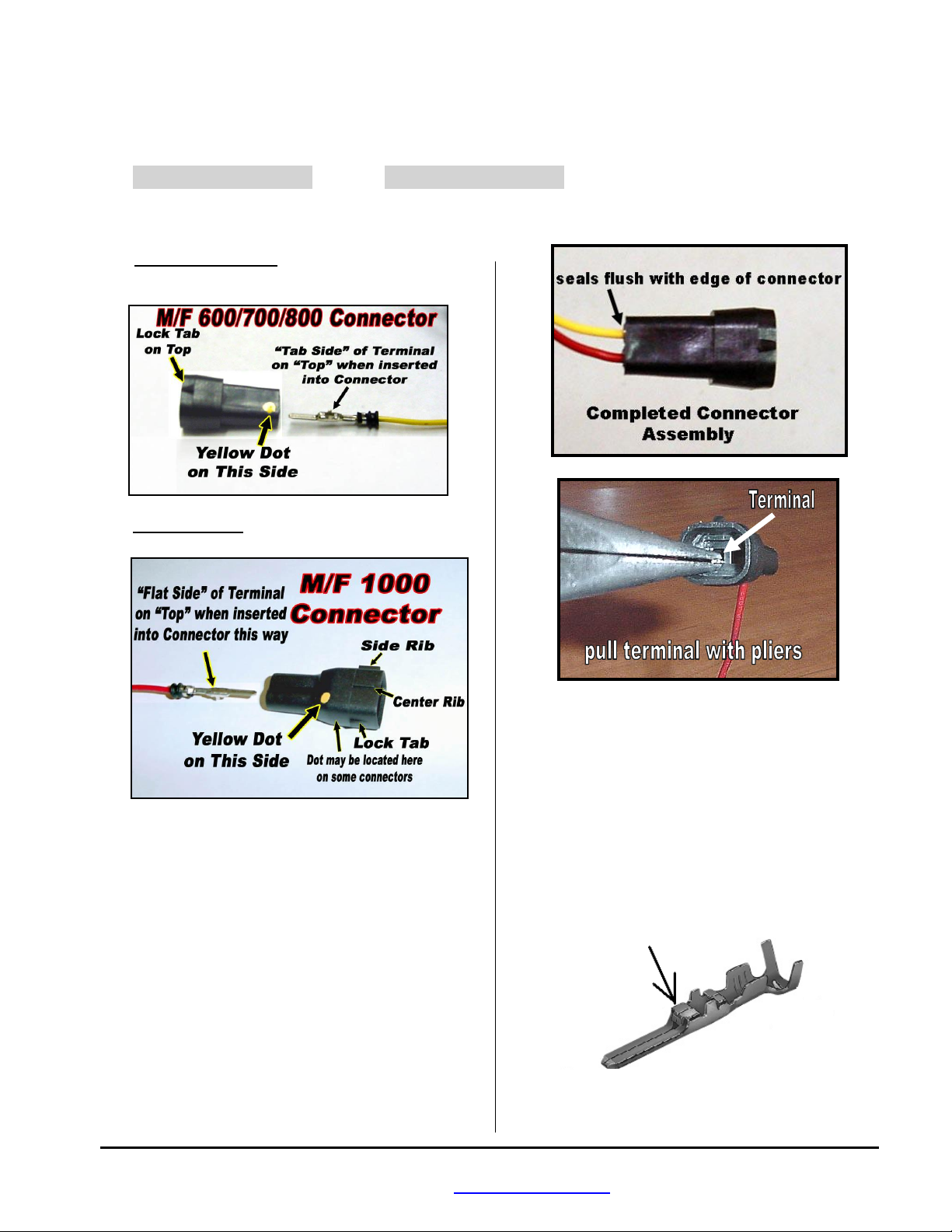
Insert the terminals into the connectors by following the steps below:
1. Non-1000 Connector: Hold the black connector
with its locking tab up. Insert the terminal with its
alignment tabs up (see picture).
1000 Connector: Orient the black connector and
pin terminal as shown in picture.
4. If a terminal must be removed, use pliers to
carefully push the terminal out of the connector.
The terminal can usually be re-inserted one more
Note: Look inside the Black Connector to verify
that the lock tab slot on the terminal will mate with
the corresponding locking protrusion inside the
connector.
2. Push the terminal into the black connector. The
terminal will go part way into the connector and
stop.
3. Using needle-nose pliers, pull the terminal the rest
of the way into the connector. You should feel the
terminal lock into place (you will feel a slight
“pop”). The rubber seal should be flush with the
end of the connector. Use care to not gouge the
terminals.
time. Don’t do this unless necessary! The terminal
tabs need to be pried up slightly before re-inserting.
See photo of terminal at right for tab location. Use a
1.2mm or 0.050” jeweler’s screwdriver to pry with.
Check to be sure that the wire can resist a slight tug
without coming out.
BoonDocker – 1585 Hollipark Dr. Idaho Falls, ID 83401 – 208-542-4411 / 877-522-7805
www.boondockers.com – email: info@boondockers.com – fax: 208-524-7381
Revised 12-14-07 Page 2 of 19
II. Installation of EFI Wiring Harness
Note: Use Dielectric Grease on all connections to help prevent corrosion on the terminals.
The EFI harness plugs into the stock sled’s injector connectors as follows:
1. Disconnect the stock harness connector from each fuel injector. Note which connector goes to which injector.
2. Determine where the control box will be mounted and how the harness will be routed. Route the harness so the
injector connectors end up near the sled’s fuel injectors.
Note: Extra harness length can be obtained by having the harness follow the routing of the fuel line to the fuel rail
(inside of the oil bottle) instead of following the sled’s harness around the outside of the oil bottle. Both methods will
work.
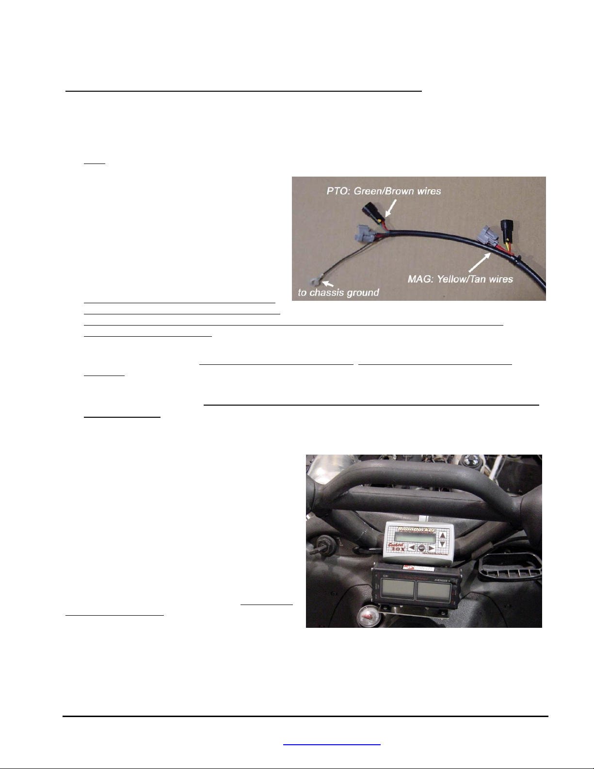
3. There is a left (PTO) and right (MAG) pair of
connectors for each injector (see picture). The
shorter length connectors go to the MAG side, and
the longer length connectors go the PTO side.
4. Plug the gray Control Box connector (female) to
the sled’s fuel injector, and the black connector to
the sled’s gray injector connector. Do this for both
the MAG and PTO sides.
Note: Be sure the black harness connectors latch
securely to the gray injector connectors. This may
require pushing the latch on the gray connector down over the tab on the black connector. Do not force the
connectors – check for bent pins.
5. Connect the Control Box harness ground eyelet to a bolt on the chassis (near the PTO-side injector for M and Crossfire
sleds). This must be made to chassis ground, not the engine ground! A good ground connection is extremely
important!
6. Use zip ties to keep the harness away from moving parts. Use reflective heat tape if the harness must be routed near
hot items such as the exhaust. Note: Twin pipes will require heat-tape to cover the harness and connectors
near the fuel rail.
III. Control Box Mounting Locations
The Control Box can be mounted under the hood, on the
dash, or on the handlebars (if pad is removed) using the
supplied Velcro strips. Before applying the adhesive
strips, thoroughly clean each surface (rubbing alcohol
works well). It is also best if each surface is room
temperature.
If the box is mounted under the hood, keep the box away
from excess heat (like the exhaust), and away from the
ignition coil.
Note: The location on the plate in front of the steering
shaft, above the exhaust pipe gets very hot! We DO NOT
recommend this location.
IV. Battery / Jumper Connector
The supplied Battery/Jumper Connector has a dual purpose. It can function as a battery connector in order to supply
voltage to the Control Box when the engine is not running, and it can function as a jumper in order to bypass the Control
Box.
BoonDocker – 1585 Hollipark Dr. Idaho Falls, ID 83401 – 208-542-4411 / 877-522-7805
www.boondockers.com – email: info@boondockers.com – fax: 208-524-7381
Revised 12-14-07 Page 3 of 19
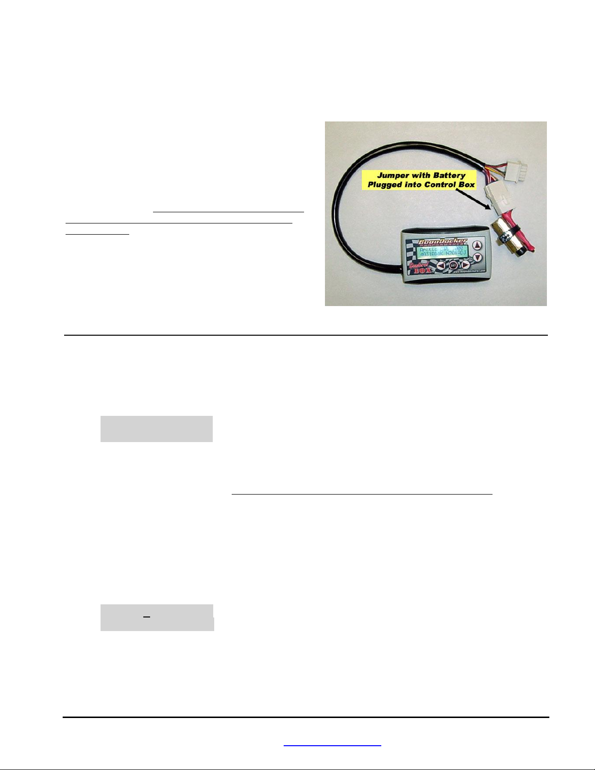
1. Battery Connector
The Control Box is designed to operate without a battery – the box will turn itself on whenever power is applied for the
fuel injectors. However, a 9-volt battery (not included) can be plugged into the box through the Control Box’s connectors
with the supplied battery / jumper connector in order to operate the box without the sled running. This battery connector
plugs into the Control Box’s nitrous connector (refer to picture
below). Secure the battery to the connector with a zip tie in
order to provide a strain relief for the 9-volt connector. The
battery can also be secured to part of the harness if it is to be
used on the sled while it is running.
The battery connector can be left plugged in during engine
operation, but the nitrous harness (if used) cannot be plugged
into the Control Box. The battery will eventually drain if left
connected to the box, so it is best to disconnect the battery
when not in use.
2. Jumper Connector
The Battery/Jumper connector can also be used to bypass the
Control Box in case the sled needs to be run without the
Control Box. Disconnect the Control Box from the EFI harness
and plug in the Jumper connector - the injectors are now
connected directly to the sled’s ECU.
V. Control Box Menus
1. Startup Screen
Every time the box is first turned on (by the engine or battery), the Startup Screen is displayed. Press any key to go to the
Main Menu. An example Startup Screen is shown below:
Arctic Cat 6-900
xxxxxxxx N2O:ADJ
In the example shown above, this screen displays the following information:
Arctic Cat Sled make
6-900 Sled model Note: Be sure the Control Box is for your make and model of sled!
xxxxxxxx Code Version This is the version of code in the box. The version of code can only be changed
by sending the box back to Boondocker.
N2O: Shows that this Control Box is nitrous capable.
ADJ Nitrous pressure regulator mode. This mode can be changed in the “Setup Menu”.
2. Main Menu
The Main Menu is shown below:
Main Fuel Stats
Menu N2O Map1U
The current selection is shown by the Right-Arrow and the cursor (underscore below the “F”). Use the arrow keys to
move the cursor. Move the cursor to the desired selection and press the “SEL” key to select the desired menu option from
one of the following:
Fuel Go to the Fuel adjust menus.
Stats Display runtime data, captured data, and recorded maximum data.
BoonDocker – 1585 Hollipark Dr. Idaho Falls, ID 83401 – 208-542-4411 / 877-522-7805
www.boondockers.com – email: info@boondockers.com – fax: 208-524-7381
Revised 12-14-07 Page 4 of 19

N2O Menus for optional Boondocker Nitrous kit (see Chapters VII and IX..).
Map Go to the Map menu.
The current Map number is displayed as “Map1U”. This indicates that map number 1 is being used and it is Unlocked.
3. Fuel Adjust Menus
This selection is used to make fuel adjustments. There are up to seven Fuel adjust screens (examples shown below). Fuel
screen1 will be displayed after moving the cursor to the Fuel selection on the Main Menu and pressing the “SEL” button.
Go to the next screen by pressing the “SEL” button. After pressing the “SEL” on the last Fuel adjust screen, you will
return to the Main Menu. Use the Left/Right Arrow keys to switch between settings. Use the Up/Down Arrow keys to
change the setting values. Sample Fuel adjust screens are shown below (actual rpm settings and number of screens may be
different for your model).
Fuel screen1: M1L LO MD N2 DL
3000 00 00 00 00
Fuel screen2: M1L LO MD HI tr
5000 00 00 00 00
Fuel screen3: M1L LO MD HI tr
6700 00 00 00 00
The control box allows fuel adjustments to be made according to the following two factors: RPM and Engine Load.
RPM Regions:
Up to seven RPM regions are pre-programmed in the control box which allows fuel adjustments to be made at specific
RPM settings. Whenever the engine RPMs are between these specific regions, the fuel adjustment will be the result of
the adjacent RPM fuel settings blended together. For example, the fuel setting at 5000 RPM is centered at 5000 RPM,
but this value also has an effect on fuel whenever RPMs are above 3000 RPM and below 6700 RPM (the two adjacent
settings for this example). Suppose the 3000 fuel setting is at “4” and the 5000 fuel setting is at “8”, so if engine rpms
are at 4000 the actual fuel adjustment made will be ½ of “4” and ½ of “8” which is “6”.
Load Ranges:
Each RPM Region is split into 3 load ranges: LO (low), MD (medium), HI (high). Each load range is roughly equivalent
to the throttle position divided into thirds: LO is closed throttle (idel) to 1/3 open, MD is 1/3 to 2/3 open, and HI is 2/3 to
full open. During light-throttle conditions (slow cruising or deceleration), the LO RPM settings will be used. During
part-throttle conditions (normal or faster cruising), the MD RPM settings will be mostly used. During heavy-throttle
conditions (accelerating or heavy load operation), the HI RPM settings will be used.
3.1 Fuel Screens (RPM Adjustments) M1L LO MD HI tr
3000 00 00 00 00
Below is a description for each field show in the above sample screen:
M1L This displays current map that is being used – in this case, M1 stands for Map1, and L indicates the map is
Locked (changes are not allowed). Five possible fuel maps can be used. Each map consists of all the fuel
settings for a particular setup. If the map is Locked, the settings cannot be changed and the up/down buttons
have no effect. If U is displayed, the map is Unlocked, adjustments can be made to any setting and these
changes will be automatically saved to the selected map. Refer to the Load/Copy sections for more details about
how to Lock, Unlock, Load, and Copy different Maps.
3000 This is the RPM Region for the fuel adjustments on this screen. For this example, this screen’s adjustments will
be centered at 3000rpm. There can be from 3 to as many as 7 rpm regions depending on the program version.
The effect of the 3000rpm setting tapers off until 5000rpm, while the effect of the 5000rpm setting ramps up as
rpms go towards 5000. The other regions work similar to this.
Fuel screen4: M1L LO MD HI tr
7800 00 00 00 00
Fuel screen5: M1L LO MD HI tr
8100 00 00 00 00
Fuel screen6: M1L AM DR Sens
ACEL 00 00 00
BoonDocker – 1585 Hollipark Dr. Idaho Falls, ID 83401 – 208-542-4411 / 877-522-7805
www.boondockers.com – email: info@boondockers.com – fax: 208-524-7381
Revised 12-14-07 Page 5 of 19

LO / MD / HI These are the engine Load settings for each RPM region. Since engine load is directly related to
throttle position, each load range is equivalent to the following approximate throttle positions:
LO = 0 up to 1/3 throttle
MD = 1/2 up to 2/3 throttle
HI = 2/3 up to full throttle
tr This adjustment is to Trim the PTO cylinder (injector connector with green/brown wires). This is used to add
or subtract fuel on the PTO side if fine-tuning is desired. The LO adjustment is not affected by the Trim value –
trim is only used for the MD and HI settings. It is best to tune the right (mag) cylinder first then make
adjustments to the left (PTO) cylinder if necessary. If more than a small amount of adjustment is required
(greater than plus or minus 7), check for other problems first (such as incorrect harness connections to the PTO
cylinder).
00 Fuel adjustment value. Each setting can go from –99 to 127. Refer to the EFI tuning section for general tuning
guidelines. A value of 00 means no fuel adjustment will be made and the original injector signal will be passed
through unmodified. Negative values will reduce the fuel. Positive values will increase the fuel.
Note 1: Each number is equal to about 1/2% of the total available fuel. The maximum available fuel will vary
with each engine as well as with elevation and air temperature.
Note 2: It is possible to max the injector (duty cycle > 100%) before the adjustment setting is maxed! Pay
careful attention to EGT’s, O2 readings, and fuel pressure when running with engine mods that require a lot of
additional fuel!
3.2 Fuel Screen (ACEL Adjustment) M1U AM DR Sens
ACEL 00 00 00
This is the last screen displayed when in the Fuel menus. This screen is used to control fuel when the control box senses
acceleration (like an accelerator pump). Below is a description for each field show in the above screen:
M1U This displays current map that is being used – in this case, M1 stands for Map1
AM This displays the Amount of fuel to be added (if number is positive) or subtracted (if number is negative)
during Acceleration. This fuel amount will be summed with any other current fuel modifications being made
by the Control Box. This means during acceleration the final fuel adjustment amount will be the amount due
to the Control Box RPM and/or Nitrous settings in addition to the AM fuel setting.
DR This displays the Duration in engine cycles that the fuel shown in AM will modify the existing fuel during
Acceleration. The accelerator pump feature will be turned off if this value is zero and no fuel adjustments will
be made. The Acceleration fuel adjustment will be turned off whenever deceleration is detected (throttle is
backed off) regardless of the DR value.
Sens This displays the Sensitivity that is used to detect engine acceleration. Higher numbers make this Less
sensitive. Do not use zero, or acceleration will be on all the time! Suggested values are between 6 and 20,
start with a value between 8 and 10.
Note: The Stats Screen will display an “A” and a
solid block on the right-side of the screen to indicate
when the Accelerator pump feature is active as
shown:
Stats Screen indicating Acceleration:
Run 35/40 F 10 █
5500 MD █ █ █ A
4. Map Menus
From the Main Menu, select Map1U to go to the Map Menu (shown below). This screen is used to
Load/Copy/Lock/Unlock saved “maps” that contain fuel and N2O settings. Five maps (Map1-Map5) are available.
Lock ULock StUp
Load Copy Quit
BoonDocker – 1585 Hollipark Dr. Idaho Falls, ID 83401 – 208-542-4411 / 877-522-7805
www.boondockers.com – email: info@boondockers.com – fax: 208-524-7381
Revised 12-14-07 Page 6 of 19
 Loading...