

Page 1

Page 2

Hardware Kit Bag
(4) 8mm x 30mm allen head bolts
(4) 8mm x 25mm bolts
(4) 8mm lock nuts
(2) Gold exhaust springs
(4) High tension exhaust springs
(6) 8” zip ties
(4) 4” zip ties
(2) 3/8” barbed unions
(4) #6 hose clamps
(1) Turbo mount template
Separate Parts:
1548 Turbocharger Indexed to turbo bracket
Adustable actuator
Exhaust inlet
Exhaust outlet
Body bracket for muffler
Muffler
(2) 3.5” x 12” decals
Silicone Kit Bag
3” piece of 2” balck silicone
(2) 2.125” piece of 2.25” pieces of black
silicone
(4) #36 hose clamps
(2) #32 hose clamps
Oil Drain Kit Bag
Oil drain line with banjo fitting installed
(1) #8 x 1/2” self tapping screws
(2) rubber insulated clamps
12mm banjo bolt
(2) copper washers
#12 hose clamp
Oil Feed Kit Bag
Oil feed hose
1/2” x 4an adaptor
Fuel System Kit Bag
Fuel line assembly
(2) Auxillary injectors
(2) #4 hose clamps
(2) 1/4” x 1.5” allen bead bolts
Intercooler Kit Bag
Pull fan
(2) 1/4” x 1/2” bolt
1/4” x 3/4” bolt
(3) 1/4” lock washers
Fan power adaptor harness
Intercooler
Boondocker control box
Control box
Air solenoid valve
Battery jumper
Velcro
30” of boost line
(5) 8” zip ties
(5) 4” zip ties
Clutch kit
Team Rooster weights
Red with black/gold striped primary
spring
Green with silver secondary spring
Performance Plus Kit Only:
8 Valve seals
8 Valve springs
Headgasket
Revised 7/9/2013 Page 2 of 17
www.boondockers.com………………..... ……….………………....877-522-7805
Page 3
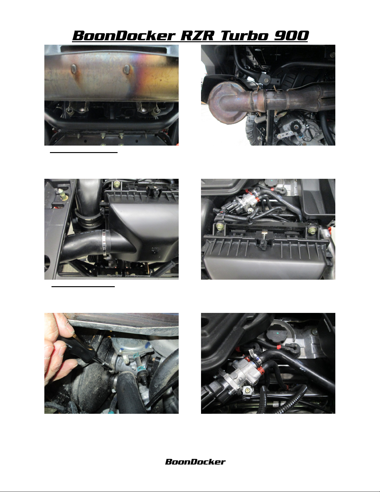
1.REMOVE MUFFLER Remove the 2 exhaust
springs connected to the bottom of the muffler.
2 Remove the 2 exhaust springs connecting the
header to the muffler. The muffler can now slide
off the hangers. Slide toward the passenger side
of the vehicle.
3. REMOVE AIRBOX Remove the rubber
hose connecting the airbox to the air intake.
5. Loosen the 2 clamps holding the airbox to the
throttle bodies.
4. Remove the 2 bolts connecting the airbox to
the airbox bracket.
6. Remove the breather hose from the Idle Air
Control unit. Pull the airbox out of the vehicle
and reinstall the bolts, grommets and spacers to
the airbox mounting bracket.
Revised 7/9/2013 Page 3 of 17
www.boondockers.com………………..... ……….………………....877-522-7805
Page 4
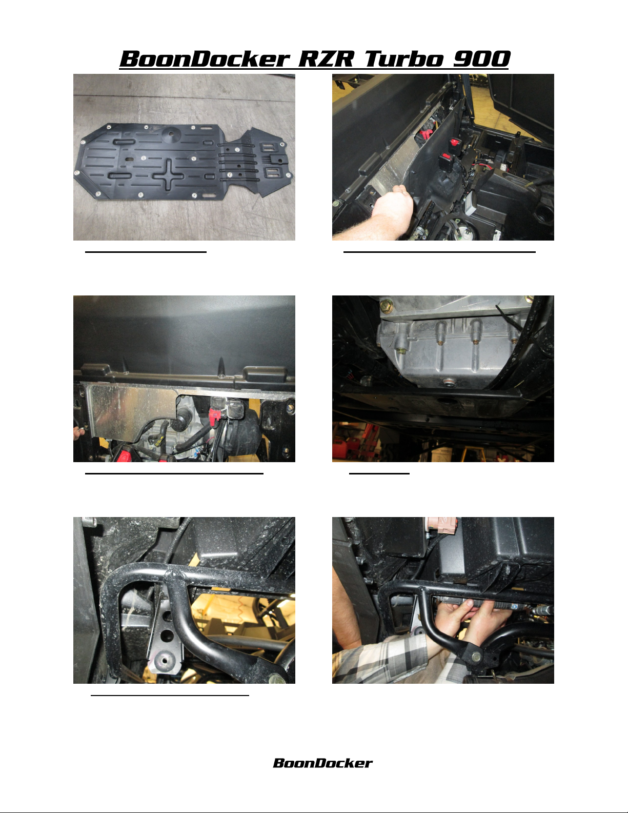
7. REMOVE SKIDPLATE Remove the 14
bolts and washers that fasten the skidplate to the
frame.
8. REMOVE SEATS AND REAR PANEL
Remove the seats from the vehicle and the rear
panel using a T 25 torx head bit.
9. REMOVE ENGINE HEAT SHIELD
Remove the 7 bolts holding the heat shield in
place, pull the heat shield down to remove it
10. DRAIN OIL Remove the factory drain plug
and set aside. We will not be reinstalling this
plug.
from the vehicle.
11. REMOVE MUFFLER MOUNT Using an
airsaw or hack saw, remove the passanger side
muffler mount to make room for the turbo inlet.
12. Cutting the bracket from the backside with an
airsaw is ideal. File any sharp edges.
Revised 7/9/2013 Page 4 of 17
www.boondockers.com………………..... ……….………………....877-522-7805
Page 5
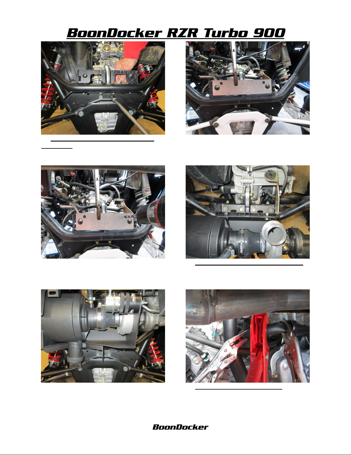
13. PREPPING THE STOCK MUFFLER
BRACKET Remove the nuts from the lower
rear engine mount bolts.
14. Center the turbo mount template to the stock
muffler bracket as shown. Secure the template to
the vehicle with vise grips.
15. drill 2x 11/32” holes into the stock muffler
bracket as shown.
16. MOUNTING THE TURBO/BRACKET
Using the 2 5/16 x 3/4” bolts, fasten the turbo
bracket to the stock muffler bracket. Use the
11/32” holes drilled in the previous step.
17. Using the factory lower engine mounting
bolts, fasten the bottom of the turbo bracket to
the vehicle.
18. INSTALLING WATER LINES Follow
the factory coolant line from thethermistat lamp
each side of the 90 degree bend with vise grips.
Make a cut after the 90 degree bend.
Revised 7/9/2013 Page 5 of 17
www.boondockers.com………………..... ……….………………....877-522-7805
Page 6
19. Rotate the 90 degree bend coming from the
thermostat toward the rear of the machine.
20. Route the 15” water line from the inside of
the turbo to the 90 degree coming from the
thermostat.
21. Trim line as needed, then install the 3/8”
barbed union and fasten with 2 #6 hose clamps.
23. Trim line as needed and fasten this
connection with the 3/8” barbed union and (2)#6
hose clamps.
22. Route the 24” water line to the outside of the
turbo to the open end of the coolant line cut in
step 18.
24.INSTALLING OIL DRAIN LINE Locate
the oil drain line and fasten the 5/8” side of the
hose to the turbo oil drain using a #12 hose
clamp.
Revised 7/9/2013 Page 6 of 17
www.boondockers.com………………..... ……….………………....877-522-7805
Page 7
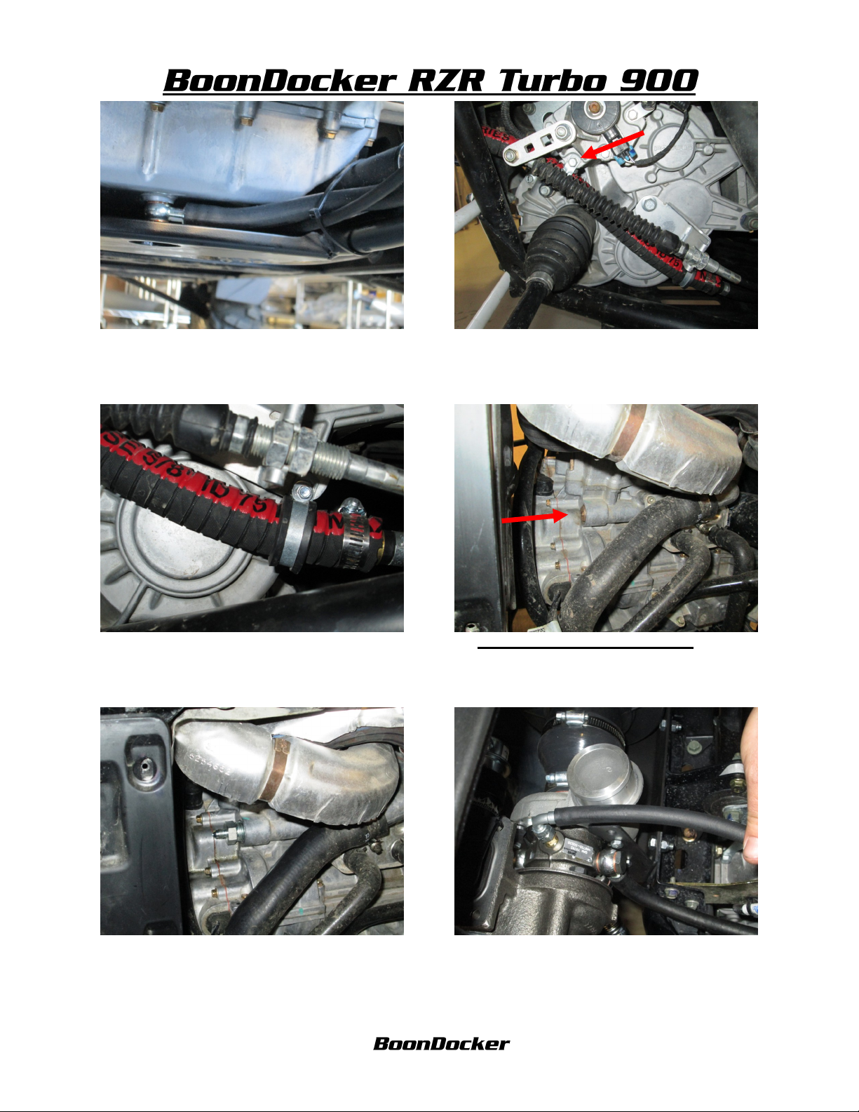
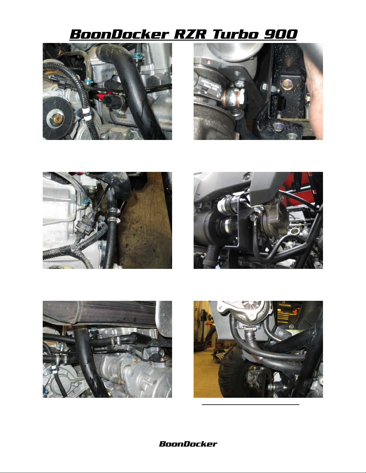
25. Route the 3/8” end of the oil drain line to the
oil drain on the motor. Use the 2 copper washers
to sandwich the banjo fitting and fasten to the
motor with the 12mm bolt. Zip tie as shown.
26. Use the provided rubber clamp and existing
bolt to fasten the oil drain hose to the motor.
Make sure the hose is not touching any abresive
objects or heat source
27. Using the remaining rubber clamp and self
tapping screw fasten the oil drain hose to the
shifter cable bracket as shown in picture.
29. Apply a thread sealant to the 1/2” pipe
thread side of the 4an adaptor then install the
adaptor to the motor.
28. INSTALLING OIL FEED LINE
Remove the 1/2”oil plug from the front of the
motor.
30. Locate the oil feed line and fasten to the oil
inlet on turbo as shown in picture.
Revised 7/9/2013 Page 7 of 17
www.boondockers.com………………..... ……….………………....877-522-7805
Page 8

31. Route the oil feed line from the turbo and to
the 4an adaptor installed on step 29. Make sure
to route hose away from any heat source and
abrasive objects.
32. INSTALLING FUEL LINE Locate and
cut the factory fuel line as shown in picture.
33. Insert a #4 hose clamp from either side of the
factory fuel line. Using the Boondocker fuel line
“T” into the stock fuel line as shown.
35. With the 4-hole flange inserted between the
turbo and inlet, fasten the turbo inlet to the turbo
using the 4 8mm x 25mm bolts and lock nuts.
34. INSTALLING EXHAUST INLET
Apply hi-temp black silicone to the inside of the
turbo inlet.
36. Fasten the turbo inlet to the stock header
using the 4 Boondocker hi-tension exhaust
springs. These springs are a tight fit, this is to
ensure this connection does not separate.
Revised 7/9/2013 Page 8 of 17
www.boondockers.com………………..... ……….………………....877-522-7805
Page 9
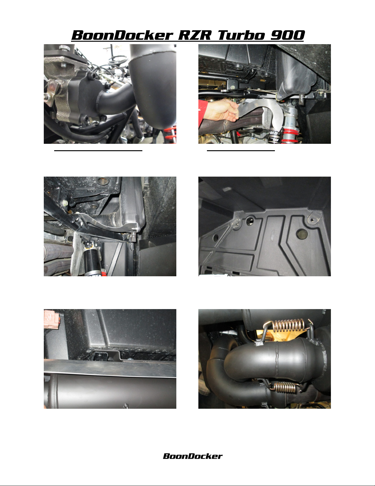
37. INSTALL TURBO OUTLET Fasten the
turbo outlet to the turbo using the 8mm x 30mm
allen head bolts.
38. INSTALL MUFFLER Remove the bed
support bracket on the passanger side of the
vehicle.
39. Install the bed support bracket replacement.
41. Pry the bed off of the mounting bracket and
slide the muffler mounting tabs in between the
bed and the bed mounting bracket. Loosen
addition bed bolts if needed.
40. Remove the 2 passenger side tie down
support brackets from the inside of the bed.
42. Align the muffler to the turbo inlet, outlet
and tie down support bracket holes. Reinstall the
support brackets and fasten the muffler to the
outlet using the 2 provided gold springs.
Revised 7/9/2013 Page 9 of 17
www.boondockers.com………………..... ……….………………....877-522-7805
Page 10

43. INSTALLING THE INTERCOOLER
Mount the fan to the intercooler using the 3
provided bolts. Note the longer bolt will need to
be used on the raised fan mounting tab.
44. Install the 3 silicone hoses and clamps to the
intercooler. Do not tighten the clamps until the
intercooler is installed, this way you can find the
best angle to access the clamp.
45. Install the grommets and spacers used from
the factory airbox onto the intercooler mounting
bracket.
47. Fasten the intercooler mounting bracket to
the stock airbox mounting bracket using the
stock bolts.
46. Slide the intercooler onto the throttle bodies
and the outlet on the compressor housing of the
turbo. Tighten the clamps connecting the
intercooler to the throttle bodies.
48. Tighten the clamps connecting the
intercooler to the turbo.
Revised 7/9/2013 Page 10 of 17
www.boondockers.com………………..... ……….………………....877-522-7805
Page 11

49. INSTALLING THE FUEL RAILS Apply
assembly lubricant to the upper o-rings on the
fuel injectors and insert them into the fuel rails.
50.Apply assembly lubricant to the lower o-rings
on the fuel injectors and insert them into the
intercooler. Route as shown. Fasten the 2 fuel
rails with the 1/4-20 x 1 1/2” allen head bolts.
51. POWERING UP THE FAN Route the fan
power harness from the fan and “T” into the
tailight power harness located under the rear
fender on the drivers side.
53. Install the 1/2” hose from the intercooler to
the Idle Air Control Unit.
52. PLUMBING THE AIR CLEANER Install
the provided intake hose from the Donaldson air
cleaner to the factory air intake.
54.Look over all the hose routing to make sure
the clamps are tight and there are no kinks or
sharp bends in the hoses. Make sure to keep
hoses away from sharp objects. Zip tie hoses.
Revised 7/9/2013 Page 11 of 17
www.boondockers.com………………..... ……….………………....877-522-7805
Page 12

55. INSTALL BOONDOCKER CONTROL
BOX Refer to control box installation
instructions.
56. CLUTCHING
Remove the clutch cover, and rear shock.
57.Remove the belt and secondary clutch.
59. Get clutch press and remove snap ring. Make
sure you mark the position of the sheaves, rollers
and helix for reinstallation.
58. Remove bolts from helix, remove helix.
60. Replace stock spring with the provided
Green/ silver spring. Roller holder is indexed to
inner spindle. Install using the press.
Revised 7/9/2013 Page 12 of 17
www.boondockers.com………………..... ……….………………....877-522-7805
Page 13

61. Install snap ring.
62. Reinstall the factory helix, Be sure to
reindex to the marks made previously on step
59. Use blue locktite when reinstalling the
factory screws.
63. Reinstall factory clutch.
65. Remove clutch cover.
64. Remove primary clutch bolt.
66. Remove clutch weights.
Revised 7/9/2013 Page 13 of 17
www.boondockers.com………………..... ……….………………....877-522-7805
Page 14

67. Install preloaded clutch weights
68.Install the red w/black and gold primary
spring. Reinstall the clutch belt and clutch cover.
Tighen all bolt to factory specs. Reisntall clutch
cover and shock.
69.FINISHING TOUCHES Be sure to refill
the coolant and oil before starting the vehicle.
Revised 7/9/2013 Page 14 of 17
www.boondockers.com………………..... ……….………………....877-522-7805
 Loading...