

Page 1

Page 2
1.
1. 1.Remove side panels, hood, seat, fuel tank, and
muffler. Save exhaust springs and rubber muffler mounts for turbo install.
2.Remove stock air box, remove fuel line
bracket. Sand back surface flat for mounting.
3.Remove factory TBAP sensor from stock air
box and zip tie to over structure.
5. With ECU in place hold the fuel filter on the
back side of fuel line bracket to ensure proper
fitment, drill a 1/4” hole in the tab for bracket
mounting
4. Un-bolt and un-strap the stock oil tank. Leave
oil line hooked up.
6. Snap the fuel filter and fuel line into the fuel
line bracket and secure to clutch cover using the
1/4” bolt and lock nut. Reinstall the oil tank.
Revised 10/22/2014 Page 2 of ?
www.boondockers.com………………..... ……….………………....877-522-7805
Page 3
7. Use a punch to remove the steel center from
necessary rivets. Use a straight edge to mark the
cut line to remove lower portion of kick plate.
Leave the upper portion for side panel mounting.
8. Remove the stock exhaust deflector and seal. Install
exhaust block off plate using supplied rivets from the
top using plate as rivet backer.
9. Use the attached template to locate muffler hole
location, Center punch and then drill 2 1/2” hole for
exhaust outlet.
11.Install spring tab and heat deflector on belt
drive models using factory bolts as shown.
10. Remove front suspension bolts and install tunnel
support plates, Re-install suspension bolts and finish
securing using supplied rivets..
12. Using a pair of pliers break off chassis tab in
the image and grind to match the stock contoured surface. (Not necessary to remove for
Tial exhaust system)
Revised 10/22/2014 Page 3 of ?
www.boondockers.com………………..... ……….………………....877-522-7805
Page 4
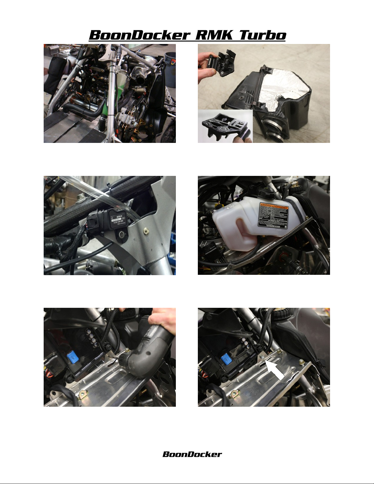
13.
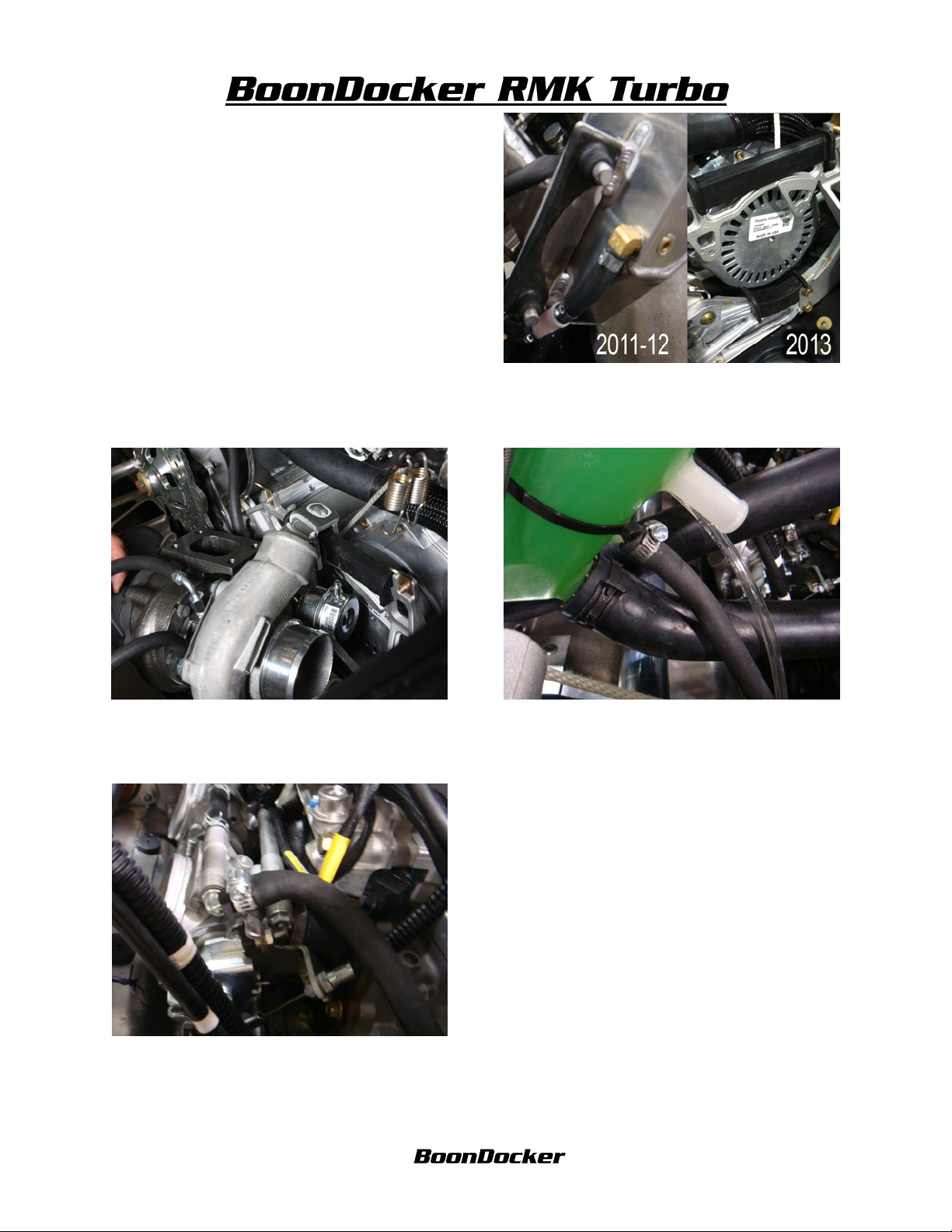
14. Attach the rubber exhaust mounts to turbo
Bracket as shown . Note: 2011-12’ are different
than 2013’.
15. Hang the turbo assembly in place using the
stock muffler mounting locations, make sure
turbo sits down on rubber mounts.
17. Route outside coolant line over to the throttle
Bodies and secure using supplied hose clamps.
16. Lower coolant level in bottle, remove stock
coolant line from coolant bottle to throttle bodies
Route the inside turbo coolant line to coolant bottle.
Proper routing will avoid pull rope, and sharp edges
18.
Revised 10/22/2014 Page 4 of ?
www.boondockers.com………………..... ……….………………....877-522-7805
Page 5

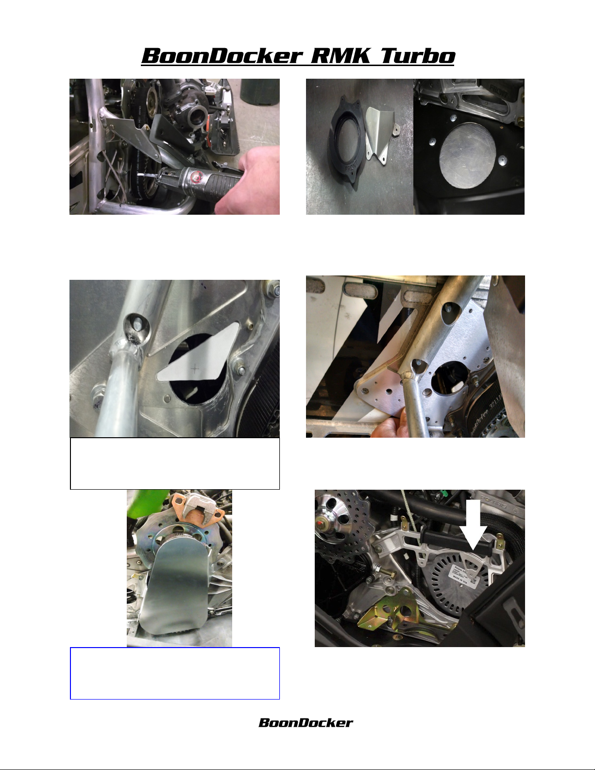
19. Tip sled onto left side (clutch towards floor)
center punch rivets to remove stud to make drilling easier. Drill all rivets holding on access
plate.
20. Using a torch or heat gun. Heat up the access
panel to break the glue bond. Note it may require prying to break loose. (use caution to prevent a fire)
21.Remove access plate, clean excess glue from
bulk head. And remove all rivet studs and shavings from bulk head. A magnet may be helpful.
22. Using a marker, Label oil ports as shown. 1top 2- center and 3. Remove oil lines 1 and 2
from the pump and engine. Port 3 will remain
unchanged. Save clamps for new line install.
23. Use the 36”supplied oil line and protective
sleeve and route to the turbo, avoid sharp edges and
heat, zip tie where necessary. Before attaching lines,
fill oil lines with injection oil, attach turbo oil line
to port labeled #1. Use 7 1/2” supplied line and
route from port labeled #2 to PTO crank bearing.
Use stock clamps to secure lines to oil fittings.
WARNING lines MUST be plugged in proper
ports. Prevent engine damage!
Revised 10/22/2014 Page 5 of ?
24.(If installing Water to Air cooler see supplement instruction at this time). Install supplied
access plate, line up with pre-existing holes and
attach using supplied hardware.
www.boondockers.com………………..... ……….………………....877-522-7805
Page 6

25. Install foot rest kick plate. (Note: install kick
plate “only install the 2 lower rivets on top running
board at this time”) the last rivet will be installed
later to adjust clearance
26. Remove the stock pipe from Y-pipe, remove
the exhaust donut and run a bead of silicone
around inside and reinstall on Y-pipe, Note:
make sure to align notches on Y-pipe to donut
27.Run a bead of silicone on the inside of the
flange on the exhaust pipe.
29.Run a bead of silicone on inside of the small
exhaust donut and install on pipe
28. Install springs from pipe to Y-pipe 2-springs
on side spring tabs and 3-springs on top spring
tab.
30. Run a bead of silicone on inside of the bell
of turbo inlet pipe. Bolt inlet to turbo using 4
bolts and 4 hole gasket . If installing stainless
Tial see next step.
Revised 10/22/2014 Page 6 of ?
www.boondockers.com………………..... ……….………………....877-522-7805
Page 7

31.Install turbo inlet and v-band clamp do no
tighten all the way, make sure it is properly
aligned and seated and snug v-band clamp.
32. Install stainless muffler into tunnel and attach to turbo using v-band clamp make sure to
properly align and seat, snug v-band do not
tighten all the way.
33.Install Tial external waste gate, rotate turbo
inlet and muffler for proper alignment using supplied clamps snug waste gate into place do not
34.Spring turbo inlet into place using the 4 long
gold exhaust springs.
tighten yet.
35. Spring muffler into place using short exhaust
spring. (At this time finish riveting the kick plat
in place, use inside rivet to adjust distance between muffler and kick plate)
36. Make sure there is no binding in exhaust
connections and the are no gaps between V-band
connections NOTE: gaps will not close by tight-
ening. Tighten all V-band and waste gate clamps
Revised 10/22/2014 Page 7 of ?
www.boondockers.com………………..... ……….………………....877-522-7805
Page 8
37.
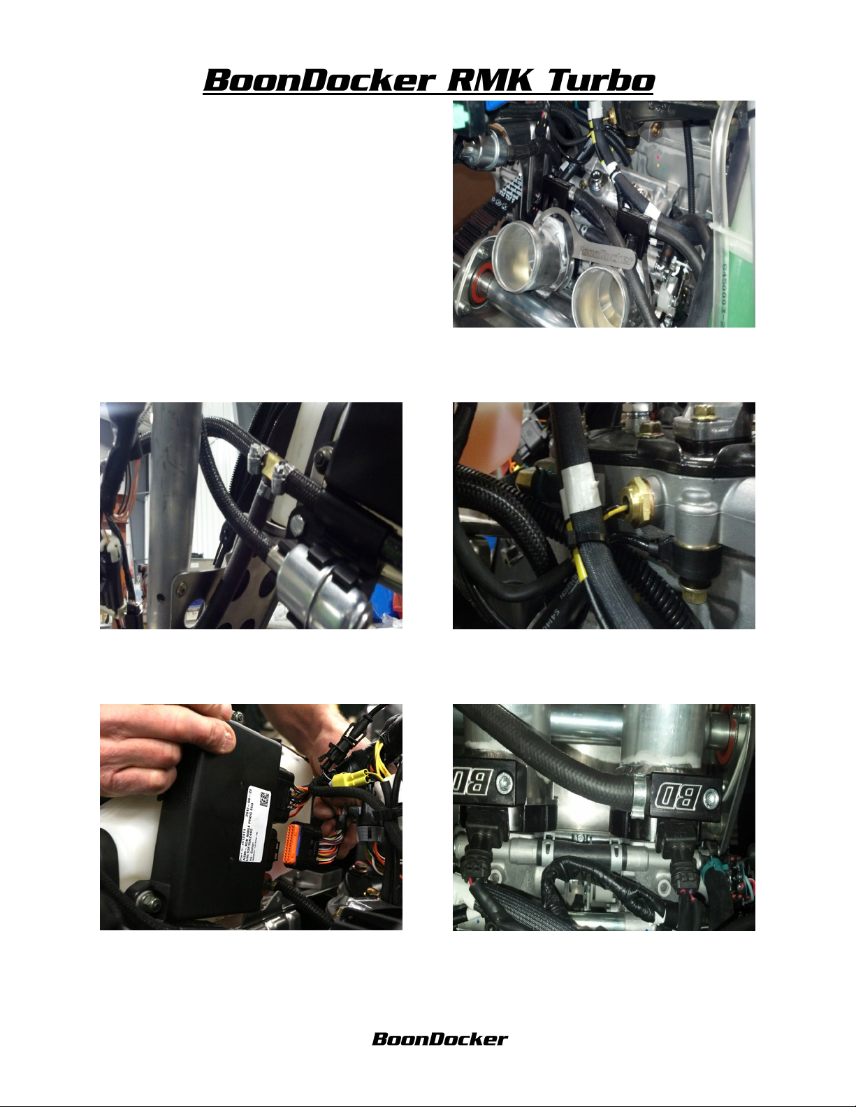
38.Install machined throttle body adapters, make
sure o-ring is in throttle body groves tighten using supplied spanner wrench NOTE: tighten un-
til compression ring bottom ,do not over tighten
39.Route fuel line from auxiliary injectors over
to fuel line bracket. Cut and splice into the fuel
line behind the bracket, NOTE: splice into the
line that does NOT have in line filter.
41. Unplug the lower multi-pin connector from
the ECU, (located on backside of oil tank) Plug
the Boondocker wire harness in to ECU and
stock connector into Boondocker harness.
40.Rotate the DET sensor as shown torque to
11- 12 ft lbs. Route wiring and zip tie to throttle
body coolant line.
42. Route the Auxiliary injector connectors to
throttle body adapters and plug into Boondocker
injectors on fuel rails. Secure with zip ties
Revised 10/22/2014 Page 8 of ?
www.boondockers.com………………..... ……….………………....877-522-7805
Page 9

43. Zip tie factory ECU plug so there is proper
clearance with out wire chaffing or rubbing.
44. Install Torque building silicone air box,
make sure not to slide on to far for proper jackshaft clearance. Tighten hose clamps.
NOTE: if installing inner-cooler see next step.
45. Install silicone hose onto throttle body adapters make sure to have proper jackshaft clearance
IF NOT installing inner-cooler go to step#49
46.Install Torque building inner-cooler, (Tech
tip, moving steering post may make install easier.) Adjust for clearance of head, electrical wiring, fuel filter, fan, and chassis before tighten-
47Locate the A/C PWR plug, (A/C plug is located in Velcro pouch above the fan near steering post. Plug the fan booster into the factory A/
C plug, and rubber connector into fan.
48.Install the fan onto the inner-cooler using the
supplied 1/4” bolts and lock washers. Route the
fan power to fan booster and secure w/ zip ties.
Revised 10/22/2014 Page 9 of ?
www.boondockers.com………………..... ……….………………....877-522-7805
Page 10

49. Locate the temp sensor wiring (located in
rear of inner-cooler or in silicone air box) route
and plug into control box harness secure with
zip ties.
51. Install charge tube, (Inner-cooler and Air
Box) Adjust for maximum clearance and tighten
clamps
53. Locate solenoid power connector from the
control box, follow stock wire harness over
steering linkage over to boost solenoid and plug
in secure with zip ties.
52.Install electronic boost solenoid using Velcro
and zip tie to secure to coolant hose. Route
3/16” line from brass fitting to top of solenoid .
54. Route 3/16” line from 90 fitting on boost
solenoid to the boost actuator on turbo bracket.
NOTE: make sure to use small zip ties on ALL
3/16” hose connections to prevent blow off..
Revised 10/22/2014 Page 10 of ?
www.boondockers.com………………..... ……….………………....877-522-7805
Page 11

55. Install fittings on the waste gate as shown,
Top cap 1-vent and 1-plug . Below Diaphragm
1-pressure Fitting, and 2–plugs, and leave the
n2o ports empty.
56. Route 3/16” line from the 90 fitting on boost
solenoid to air fitting on external waste gate on
lower diaphragm .
57. At this time check all routing! Check all fuel
lines, wiring, and hose, make sure everything is
properly secured and zip tied to prevent rubbing
and chaffing!
59.Cut out the provided template and position on
plenum as shown. Template will follow plenum
58. Remove the stock air intake plenum from
under side of the hood. NOTE: heat on the tabs
will help prevent breaking the tabs. Remove all
internal ducting.
60. Trim the oval hole out as shown
mold. Trace the oval hole as shown.
Revised 10/22/2014 Page 11 of ?
www.boondockers.com………………..... ……….………………....877-522-7805
Page 12

61.Drill the three 3/16 holes and rivet from the
inside as shown, Remove the foam from around
stock air intake Install the frog skin over the
stock air hole on plenum.
62. Install the silicone hose to turbo with two
clamps, leave loose install silicone onto adapter
on hood only one clamps will be used here for
easy hood removal.. Adjust for fit and tighten.
64.Reinstall-Fuel Tank, seat and Hood . Attach
the control box using supplied Velcro Route the
Boost pressure line from the control box to the
push to connect fitting on the Air box or Cooler.
65.Install the Clutch Kit , Primary spring, and
clutch weights, Install Secondary spring and
Helix. Recommended helix start: 40-46-36, if
less RPM desired 42-48-36 Faster up shift.
Revised 10/22/2014 Page 12 of ?
www.boondockers.com………………..... ……….………………....877-522-7805
 Loading...