

Page 1

M 1000 Race Gas Installation instructions
Step 1: Tear Down
Parts Needed: Tools Needed:
None Basic Tool Set
Air Saw
Revised 11/18/08 Arctic Cat M-1000 Turbo Installation instructions Page 1
www.boondockers.com............................BoonDocker..........................................877-522-7805
Page 2
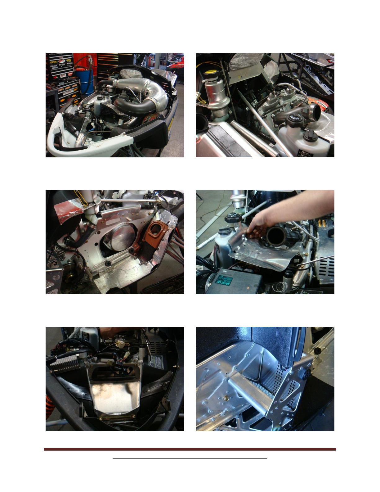
A. Remove hood and side panels. B. Remove pipe.
C. Remove can (remove the stock rubber
mount from the exhaust can, we will
need this later).
E. Remove air box and ECU.
D. Remove “Y” pipe and heat shield.
F. Remove right hand step panel and reverse
beeper.
Revised 11/18/08 Arctic Cat M-1000 Turbo Installation instructions Page 2
www.boondockers.com............................BoonDocker..........................................877-522-7805
Page 3
Step 1: (continued) Tear Down
G. Remove throttle bodies. H. Cut and remove this portion of the bulk-
head.
Step 2: Throttle bodies
Parts Needed: Tools Needed:
2- 10/32 x 3/16” barbed 90 Basic Tool Set
3/16” Brass T Lock tite
2- 2.5” pieces of 3/16” hose 10/32 tap
30” piece of 3/16” hose Drill
6- 4” zip ties
5/8 hex bracket
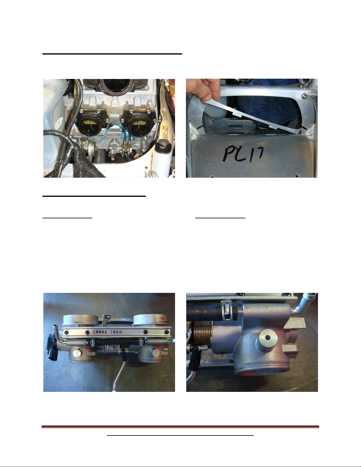
A. Mark throttle bodies with center punch. B. Drill at punch mark using 5/32” drill bit.
Revised 11/18/08 Arctic Cat M-1000 Turbo Installation instructions Page 3
www.boondockers.com............................BoonDocker..........................................877-522-7805
Page 4
Tap hole in throttle bodies using a 10-32
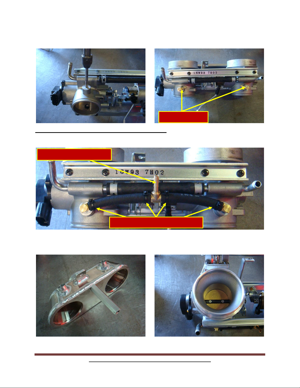
Use lock-tight here
Secure connections using small zip-ties
Connect 30”x 3/16” hose here
tap.
C. Install 10-32 x 3/16” 90° fittings, position
as shown.
Step 2: (continued) Throttle bodies
D. Install two 2 ½”x 3/16”, one 30”x 3/16” rubber boost hose, and one 3/16” brass tee.
E. Install air box mount to air box.
F. Temporarily install throttle body
machined rings and turbo air box to
throttle body.
Revised 11/18/08 Arctic Cat M-1000 Turbo Installation instructions Page 4
www.boondockers.com............................BoonDocker..........................................877-522-7805
Page 5
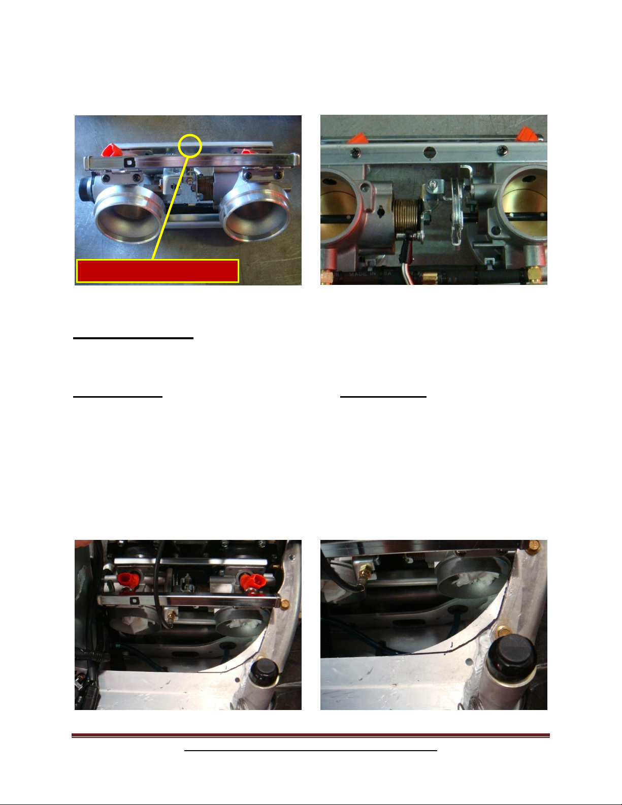
G. With the Airbox installed mark where
Mark here with air box installed
the mounting bracket hits the throttle
body cross-support.
Step 3: Air Box
H. Drill cross-support at mark using 3/8”
drill bit.
Parts Needed: Tools Needed:
Airbox Air saw
5/16 x 1” bolt Assembly lube
5/16” lock washer
2-Machined rings with o-rings
B. Reinstall the throttle bodies. Cover the
holes on the throttle bodies to keep from
getting shavings into the throttle bodies.
C. Mark bulk head as shown, and trim.
Revised 11/18/08 Arctic Cat M-1000 Turbo Installation instructions Page 5
www.boondockers.com............................BoonDocker..........................................877-522-7805
Page 6
A. Lubricate the o-rings in the Airbox,
Slide air box into place.
E. Install air box to machined rings
B. Lubricate the o-rings on the machined
rings before installing. Install machined
rings to throttle bodies.
F. Fasten air box in place using 5/16”x
1” bolt and lock washer.
Revised 11/18/08 Arctic Cat M-1000 Turbo Installation instructions Page 6
www.boondockers.com............................BoonDocker..........................................877-522-7805
Page 7
Step 4: Installing the Control Box
Parts Needed: Tools Needed:
Control Box w/instructions Basic tool set
A. SEE CONTROL BOX INSTRUCTIONS FOR INSTALLATION.
Step 5: Oil Tank/Turbo Assembly Bracket
Parts Needed: Tools Needed:
2-8mm x 20mm bolts Basic tool set
2- lock washers Assembly lube
3 hole drain gasket (packaged in turbo box)
Oil drain
Rubber grommet from stock muffler
2- rubber boot seals
2- 5/16 x ½” bolts
Turbocharger
Oil tank assembly bracket
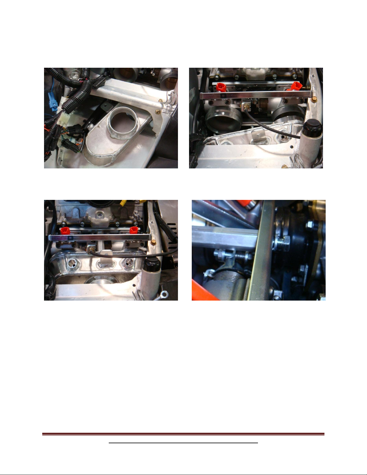
A. Install the stock rubber grommet (removed
from the stock muffler in step 1) and install it
to the oil tank assembly bracket as shown in
picture. Install the 2 rubber boot seals as
shown in picture. Important: DO NOT
LUBRICATE THESE BOOTS.
B. Loosen the 6 exhaust housing bolts on the turbo.
C. Loosen the 4 bolts on the intake or compressor housing of turbo.
Revised 11/18/08 Arctic Cat M-1000 Turbo Installation instructions Page 7
www.boondockers.com............................BoonDocker..........................................877-522-7805
Page 8
D. Locate the 2- 8mm x 20mm bolts, lock
washers, oil drain and oil drain gasket. Now
LOOSLEY bolt to turbocharger as shown, this
will make it easier to install the turbo to the oil
tank assembly bracket.
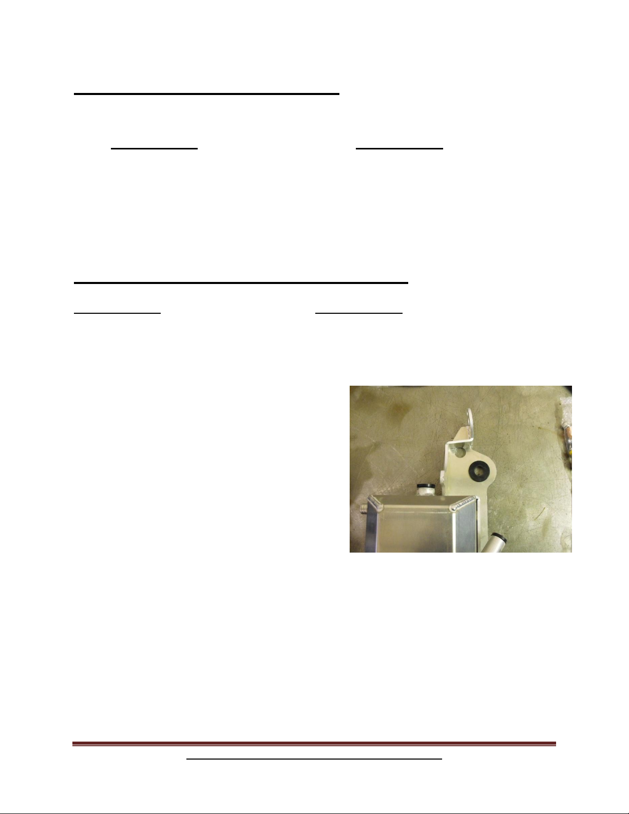
E. The center cartridge should rotate freely, rotate
the center cartridge so that the oil drain is on the
opposite of the exhaust inlet as shown in
picture.
F. Using assembly grease, liberally lubricate the
oil drain before installing the turbo into the oil
tank boot.
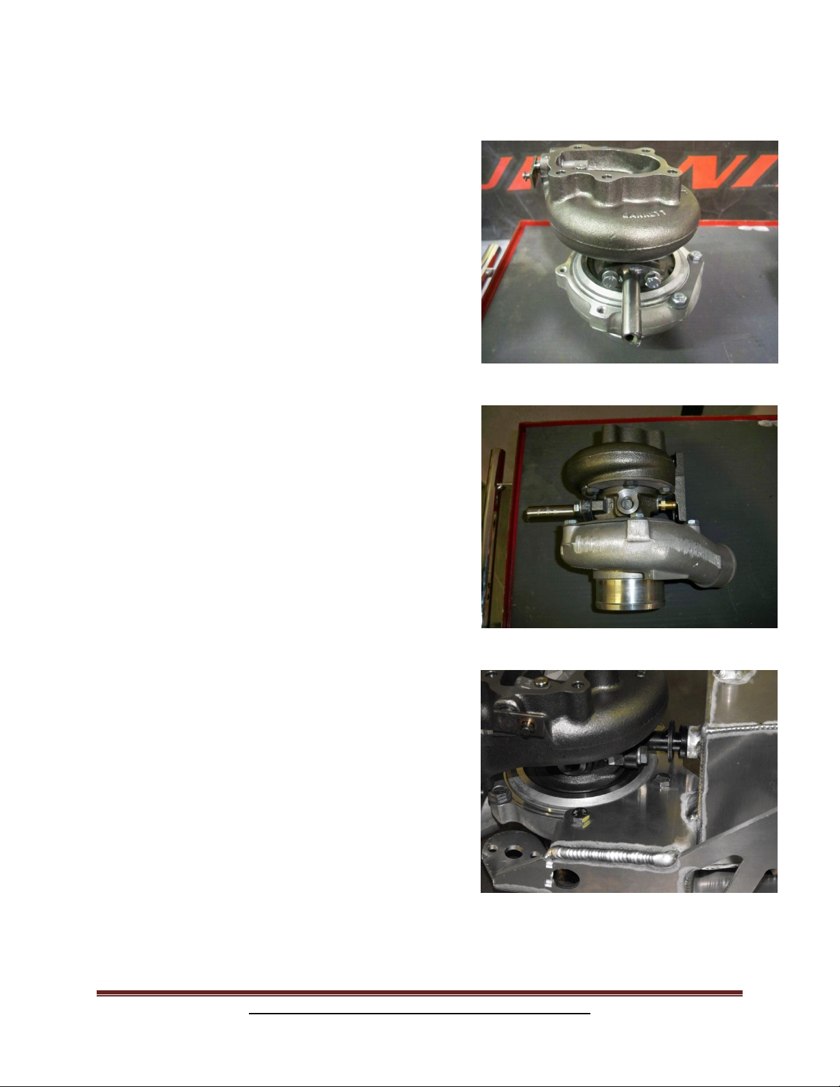
G. Insert the turbo onto the oil tank, align the
remaining 2 holes on the turbo housing with the
2 holes in the turbo mounting bracket as shown
in picture. Use the 2 provided 5/16 x ½” bolts
and tighten these first.
H. Tighten the remaining 4 bolts on the turbo
housing.
I. Tighten the 2 oil drain bolts, snug 1 bolt on
exhaust side of turbo housing.
Revised 11/18/08 Arctic Cat M-1000 Turbo Installation instructions Page 8
www.boondockers.com............................BoonDocker..........................................877-522-7805
Page 9

Step 6: Muffler
Parts Needed: Tools Needed:
Muffler Basic tool set
5- 8mm x 25mm Allen head bolts 3” hole saw
Spring tab Die grinder
¼” x ½” bolt with lock nut 2 ¼” hole saw
Muffler support with rubber bumper
2- Aluminum rivets
4- Gold exhaust springs
Turbo oil tank assembly
12” of heat tape
A. Using the provided 12” piece of heat tape.
Wrap the plastic wire loom on the coolant line
as shown in picture.
B. Mount the oil tank/ turbo assembly to the sled using the stock exhaust can mounts as
shown in picture
Revised 11/18/08 Arctic Cat M-1000 Turbo Installation instructions Page 9
www.boondockers.com............................BoonDocker..........................................877-522-7805
Page 10

3”
1 7/8”
Hole center
Be sure to trim here for best fit
C. Using a 3” hole saw make this first cut as shown in picture.
D. Using a 2 ¼” hole saw make this first cut as shown
E. NOTE: You will have to do additional trimming in the holes to get the muffler to fit, use a die
grinder for this step (see below). You can now fit the muffler inside the foot rest.
Revised 11/18/08 Arctic Cat M-1000 Turbo Installation instructions Page 10
www.boondockers.com............................BoonDocker..........................................877-522-7805
Page 11

F. From the inside of the footrest, find the center
row in the vertical hole pattern and the hole in
the very bottom of the horizontal pattern.
Install the spring tab here using the ¼” x ½”
bolt with lock nut as shown in picture.
G. Using the hole pattern on the front of the foot
rest count 6 holes up on the middle vertical
hole pattern and 5 holes up on the right vertical
hole pattern. Fasten the muffler support
bumper here using the 2 aluminum rivets as
shown in picture.
H. Trim 3 rounded spots on the foot rest as shown and mount the reverse beeper.
Revised 11/18/08 Arctic Cat M-1000 Turbo Installation instructions Page 11
www.boondockers.com............................BoonDocker..........................................877-522-7805
Page 12

I. Install the 5 hole muffler flange to the turbo exhaust housing using the 5- 8mm
x25mm Allen heat bolts. Install the 4 gold springs as shown.
Step: 7 Fuel System
Parts Needed: Tools Needed:
Fuel regulator fitting (Copper) Basic tool set
1/8” NPT x 1/8” PTC 90 Vise
1/4 “ flat washer Drill w/ 5/16” drill bit
Bulkhead fitting with 1/8” push to connect Nut driver
5/16 nylon lock nut
4- 8” cable zip ties
Note: The 2008 and older sleds will need a
replacement pump provided by Boondocker.
A. Disconnect and remove the electrical connector for
fuel pump, fuel line, brass fitting and the nut shown
in picture, then remove the factory fuel pump from
the gas tank.
Revised 11/18/08 Arctic Cat M-1000 Turbo Installation instructions Page 12
www.boondockers.com............................BoonDocker..........................................877-522-7805
Page 13

B. Locate the brass fuel regulator fitting and using a
9/16” socket press the fitting on the stock fuel
regulator using a vise as shown in picture.
C. Thread the 1/8 push to connect 90 into the copper cap
as shown in picture
D. Reinstall the fuel pump in gas tank.
E. Find a flat surface on the fuel tank to mount the bulkhead fitting. Drill a 5/16” hole and
install the bulkhead union in gas tank. Fasten the bulkhead fitting using the provided 5/16
lock nut and ¼” washer tighten using a nut driver. IMPORTANT: Do not over tighten this
fitting it will break.
Revised 11/18/08 Arctic Cat M-1000 Turbo Installation instructions Page 13
www.boondockers.com............................BoonDocker..........................................877-522-7805
Page 14

Step: 8 Fuel Rail installation
Parts Needed: Tools Needed:
2- Auxiliary fuel injectors 10- 4” zip ties Basic Tool Set
5- Size 4 hose clamps 10- 8” zip ties Thread sealant
¼” pipe plug 5/16 x ¾” bolt Assembly grease
¼ npt x 5/16” hose barb 90 5/16 lock washer
5 way rubber molded splitter Fuel rail
5/16 Brass T 20” of EFI fuel line
4- #4 hose clamps Auxiliary injector harness
A. Locate the ¼ pipe plug, ¼” 90, 2 injectors and fuel
rail, assemble as shown in picture. Be sure to use
assembly lubricant on the injector o-rings and pipe
sealant on the brass fittings.
B. Install the fuel injector assembly to the Boondocker
air box and fasten using the 5/16 x ¾” bolt and lock
washer, Again Be sure to lubricate the injector o-rings
with assembly lubricant.
C. Install the 5/16” Brass T as shown in picture.
Fasten with the 2 #4 hose clamps.
D. Using the provided 5/16” fuel line, connect the newly
installed T Boondocker fuel rail. Fasten this connection
with the remaining 2 #4 hose clamps.
E. Install the Boondocker auxiliary injector harness to the
Boondocker injectors and route the harness to the
Boondocker control box.
Revised 11/18/08 Arctic Cat M-1000 Turbo Installation instructions Page 14
www.boondockers.com............................BoonDocker..........................................877-522-7805
Page 15

Step: 9 Intercooler
Parts Needed: Tools Needed:
Intercooler Basic tool set
Rubber bumper with 5/16 studs w/ lock nuts
Intercooler mounting bracket
2.5” x 3” charge tube
5” of 2.5” silicone
1 2.5”x 3” silicone hump hoses
4- #40 hose clamps
30” of 3/16 hose
Factory air temp sensor
Blow off valve
A. Mount ADA temp sensor.
(see control box instructions)
B. Relocate power regulator/CCU as shown.
A. Install 5”x 2 ½” silicon hose to air box.
Revised 11/18/08 Arctic Cat M-1000 Turbo Installation instructions Page 15
www.boondockers.com............................BoonDocker..........................................877-522-7805
B. Install 3”x 2 ½” charge tube and 2 ½”
hump hose to air box.
Page 16

C. Install intercooler, and bolt to control arm
bolts.
D. Install rubber mount with 5/16” studs to
inter cooler, drill and bolt lower bracket
to bulkhead.
E. Install blow off valve to intercooler.
F. Connect 30”x 3/16” hose from throttle
bodies to blow off valve. Fasten with 4” zip tie.
Revised 11/18/08 Arctic Cat M-1000 Turbo Installation instructions Page 16
www.boondockers.com............................BoonDocker..........................................877-522-7805
Page 17

Step 10: Oil System
Parts Needed: Tools Needed:
Power adapter harness for oil pump None
4- 4” zip ties
A. Disconnect the factory fuel pump harness and plug in
the Boondocker adaptor harness.
B. Route the oil pump harness to the newly installed
molded connector.
C. Route the oil pump harness from the oil pump to the newly installed power adaptor. Zip tie
away from any sharp or moving objects.
Step 11:Exhaust Pipe
Parts Needed: Tools Needed:
Air saw or band saw
4- 8mm non Nylon lock nuts Welder
Stock pipe Basic tool kit
Boondocker turbo inlet Grinder or sand paper
4- 8mm x 25mm bolts
4- High tension exhaust springs
A. Remove stock heat shield from pipe.
Revised 11/18/08 Arctic Cat M-1000 Turbo Installation instructions Page 17
www.boondockers.com............................BoonDocker..........................................877-522-7805
Page 18

B. Cut the exhaust pipe right after the weld on the
inlet side as shown in picture. You will also
need to grind about 1.5” inches off the factory
weld of the pipe as shown in picture.
C. Sand the end of the pipe and inlet for a clean
weld on the pipe.
D. Using the provided 8mm bolts and nuts, bolt the
turbo inlet to the exhaust housing on the turbo
as shown Note: the exhaust housing side of the
turbo should still be loose, this will allow you to
rotate the housing as needed to fit the exhaust
pipe.
E. Reinstall the bottom heat shield on the pipe and
install the exhaust pipe as shown in picture. Be
sure to spring the pipe in place to ensure proper
placement (use factory springs).
F. Rotate the inlet to the exhaust pipe for a proper
fit and tighten at least 2 bolts on the exhaust
housing side of the turbo to fasten the turbo in
place.
G. We are now ready to weld the inlet to the
exhaust pipe. Either mark the inlet and pipe with
a permanent marker and remove pipe to tack
and weld, or If you plan on tacking the inlet to
the pipe on the sled, be sure to disconnect the
ECU. Failure to follow this step will result in
damage to your ECU. Remove pipe and finish
the weld.
NOTE: Do not reinstall the exhaust pipe until
step 13.
Revised 11/18/08 Arctic Cat M-1000 Turbo Installation instructions Page 18
www.boondockers.com............................BoonDocker..........................................877-522-7805
Page 19

Step 12: Installing Water Lines And Actuator
Parts Needed: Tools Needed:
2-Banjo style water fittings 1 @ 17” 1 @ 19’’ Basic tool set
2- Bolts for Banjo fittings T20 torx head bit
4- Copper washers High temp silicone
1-¼” x ¼” barbed fitting
Actuator
Actuator extension rod
2 nuts for actuator
E-clip for waste gate
2- #4 hose clamps
Heat deflector plate
A. Before reinstalling the exhaust pipe. Remove the 5
hole muffler exhaust flange from the turbo, and
remove the fastener pin that holds the turbo/oil tank
assembly to the sled. This will allow you to pull the
turbo/oil tank away from the sled to give you better
access to the back side of the turbo.
B. Tighten the remaining bolts on the exhaust housing
side of the turbo. It is a good idea to double check
all bolts on the turbo to make sure they are tight.
C. Install the 19” water line to the inside of the turbo,
and the 17” water line to the outside of the turbo as
shown in picture. Be sure to use 1 copper washer on
each side of the banjo fitting to ensure a proper seal.
D. While the turbo/oil tank assembly is loose bolt on the turbo actuator with the barb facing
up as shown.
Revised 11/18/08 Arctic Cat M-1000 Turbo Installation instructions Page 19
www.boondockers.com............................BoonDocker..........................................877-522-7805
Page 20

E. Install the actuator rod to the actuator. Important:
Pay close attention when setting your actuator tension.
Adjust the actuator rod just enough to where it easily
slips on the waste gate arm and does not rattle. Note:
you should not have to pull the rod to get it to fit, when
properly installed the waste gate arm should have no
play.
F. Tighten the lock nut on the actuator and fasten the
actuator rod to the turbo waste gate arm using the Eclip. Reinstall the turbo/oil tank assembly to the factory
exhaust can mount.
G. Place a bead of high temp silicone around the
muffler flange as shown in picture, reinstall to turbo.
H. Reinstall the 4 gold exhaust springs to the muffler.
I. To route the water lines, tilt the sled on its side and
remove the belly plate using a T20 torx head bit.
J. Locate the factory water line that runs from the
throttle bodies to the back of the motor. Pinch the
factory water line with a pair of vise grips or other
clamping pliers and remove the factory clamp Note:
you may have to rotate the clamp to gain access to
the worm drive fastener on the hose clamp.
K. Connect the 19” water line on the turbo charger to
the back of the motor and fasten with the factory clamp
L. Trim the protective plastic cover right before the
clamp. We will use this later.
Revised 11/18/08 Arctic Cat M-1000 Turbo Installation instructions Page 20
www.boondockers.com............................BoonDocker..........................................877-522-7805
Page 21

M. Route the 17” water line from the turbo to the stock
water line that you just pinched off. Trim the factory
water line to proper length and connect the factory
water line to the 17” turbo water line using the supplied
¼” barb and fasten with the 2 #4 hose clamps provided
in the kit, as shown in picture.
N. Install the piece of trimmed plastic sleeving on the
upper side of the water line, this will keep the hose
from rubbing on any sharp edges (see picture).
O. While the sled is on its side, install the heat deflector
plate as shown in picture. Fasten using the factory
bolts.
Step 13: Exhaust Pipe Final Install
Parts Needed: Tools Needed:
Air saw or band saw
4- High tension exhaust spring Basic tool kit
4- 8mm x 25mm bolts Spring tool
4- 8mm top lock nuts Black high temp spray paint
4 Hole exhaust gasket (packaged in turbo box)
Exhaust Pipe with heat shield
Factory heat shield
A. For a cleaner look, paint the welded inlet on the
exhaust pipe with a black high temp spray paint.
B. Reinstall the factory heat shield on exhaust pipe.
Revised 11/18/08 Arctic Cat M-1000 Turbo Installation instructions Page 21
www.boondockers.com............................BoonDocker..........................................877-522-7805
Page 22

C. Using an air saw or band saw, trim the exhaust heat
shield as shown in picture
D. Reinstall the heat shield to the sled.
E. To save you a headache, install the 2 high tension
exhaust springs on the right side of the pipe first.
This allows you to use the exhaust pipe to torque
the springs instead of a spring puller. Be sure to
install the short hook onto the pipe side and the
long side of the spring to the Y pipe.
F. Be sure to add the 4-hole gasket on the turbo side of
the pipe. Fasten this connection using the provided
8mm bolts with lock nuts.
G. Install the remaining high tension exhaust springs
Step 14: Oil Catch Can
Parts Needed: Tools Needed:
Oil catch can Basic tool set
19” of ½ hose Drill with ¼” drill bit
¼ x1” bolt
¼” nylon lock nut
¼” flat washer
A. Set the oil catch can in place and mark, then
drill the mounting hole using a ¼” drill bit.
Revised 11/18/08 Arctic Cat M-1000 Turbo Installation instructions Page 22
www.boondockers.com............................BoonDocker..........................................877-522-7805
Page 23

B. Using the provided ¼ nut bolt and washer.
Fasten the oil catch can as shown in picture
C. Run the 19” piece of ½” hose from the
catch can to the oil tank, no clamps are
needed for this connection.
Step: 15 Charge Tube
Parts Needed: Tools Needed:
Charge tube Basic tool set
2.5” x 2” rubber reducer
2.5” x 3” hump hose
3- #40 hose clamps
#32 hose clamps
40” of Poly line
40” of 3/16 clear tubing
6 zip ties
1/8 npt x 1/8 PTC 90
Revised 11/18/08 Arctic Cat M-1000 Turbo Installation instructions Page 23
www.boondockers.com............................BoonDocker..........................................877-522-7805
Page 24

A. Install the charge tube from the intercooler
to the turbo as shown in picture.
F. B. Locate the black poly line, insert the line in the plastic push to connect fitting on the
bulkhead fitting (installed in step 7E) and connect it to the push to connect fitting on the
copper cap we installed in part 7C.
G. Install the push to connect 90 on the charge tube in the form drilled hole closest to the rear of
the sled.
H. Route the black poly line from the bulkhead fitting to the charge tube, you can use the
provided 3/16” clear tubing to cover the poly line, this will help protect the poly line.
I. Zip tie the poly line away from any sharp or moving objects.
Step 16: Final Touches
Parts Needed: Tools Needed:
Snorkel filter Basic tool set
Oil tube w/dipstick Assembly lube
A. Using assembly lubrication, thoroughly coat the
oil tube, and insert it into the oil tank.
Revised 11/18/08 Arctic Cat M-1000 Turbo Installation instructions Page 24
www.boondockers.com............................BoonDocker..........................................877-522-7805
Page 25

B. Fasten the oil tube to the bulkhead using the
factory bolt as shown.
C. Using the provided size 48 hose clamps, fasten the snorkel filter to the turbo inlet as
shown.
A. Fill oil tank with 16oz of synthetic 2 stroke
engine oil. IMPORTANT: start the sled to
make sure the oil pump is working before
installing it to the turbo.
B. Install the oil hose to the top of the turbo as
shown
C. Clean up and zip-tie all hoses.
D. Well you did it, good job. Replace the hood and side panels, oh yeah, and don’t forget
to hold on!!! Thanks for choosing Boondocker Performance Products.
Revised 11/18/08 Arctic Cat M-1000 Turbo Installation instructions Page 25
www.boondockers.com............................BoonDocker..........................................877-522-7805
 Loading...