

Page 1
Installation and Operation Instructions
Electronic Boost Controller (Rev. F1)
Contents list:
Before installation of your Boondocker Electronic Boost Controller (EBC), check the contents of your kit.
Find the appropriate list for your application in the Appendix.
Installation
After installation, calibration is required! (See page 2.)
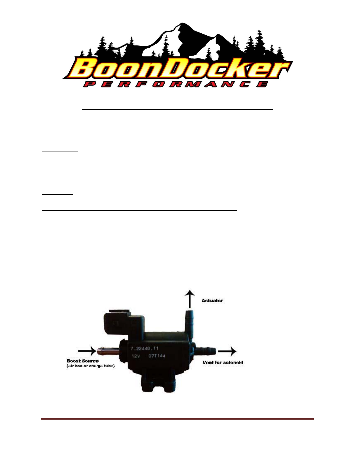
Install the boost solenoid in a pressure line between the air box (or charge tube) and wastegate actuator.
Attach the metal port of the solenoid with a 3/16” hose to the air box (or charge tube) fitting (see the
figure below). Connect the right-angle port of the solenoid with a 3/16” hose to the wastegate actuator.
Attach a short length of hose to the third port and point it downward so that it won’t get water in it. This
is the actuator vent hose. Attach the solenoid so that it is supported. Use small zip ties to secure the
hoses to the ports.
BoonDocker Performance 2379 W. Heyrend Way Idaho Falls, ID 83402
Toll Free (US) 877-552-6127 or 208-542-4411 www.boondockers.com
Revised 10-28-11 Electronic Boost Controller install/operation instructions Page 1
Page 2

Installation (continued)
Attach the electronic boost controller (EBC) mounting bracket to a convenient location on the console or
handlebars. Slide the EBC onto the bracket.
Connecting the EBC harness to power is different for every sled:
For Polaris Dragon, the EBC harness plugs into accessory power near the top of the firewall.
This connector has a red/white and brown wire. Be sure that the molded rubber EBC connector
having the male pin with the red wire plugs into the sled harness, aligning with the red/white
wire. The other EBC connector having the female pin with the red wire can be used for the oil
pump and/or fan. Be sure that red (or red/white) wires go to red wires and brown wires go to
brown wires.
For Polaris RMK Pro, the EBC harness plugs into accessory power under the left side panel. It
is the white connector labeled “DC Power”.
For Polaris RZR, the EBC harness plugs into the accessory power provided by the relay that
powers the intercooler fan. Be sure that the molded rubber EBC connector having the male pin
with the red wire plugs into the relay harness so the colors line up. The other mating rubber
molded connector with the pin with the brown wire that is exposed will plug into the fan wiring
harness. The two position connector with the brown and blue wires will plug into the new
supplied turbo harness going to the fuel control box. This will provide the boost pressure signal
to the fuel control box.
For Arctic Cat M8 and M1000 WITHOUT a fuel pump booster, unplug the fuel pump at the
right side of the firewall and plug the EBC harness in line so that all the black connectors are
used.
For Arctic Cat M8 and M1000 WITH a fuel pump booster, only the fuel booster connects in
line between the fuel pump and its power connector. DO NOT CONNECT THE EBC IN
LINE WITH THE STOCK HARNESS. DO NOT PLUG THE EBC INTO THE FUEL
BOOSTER CONNECTOR WITH THE RED AND BLACK WIRES. One of the black
connectors on the EBC harness plugs into the extra connector on the fuel pump booster. The
other black connector on the EBC harness is used only for the optional auxiliary injectors. DO
NOT ATTEMPT TO USE POWER FROM THIS CONNECTOR OR FROM THIS
POWER CIRCUIT FOR ANY OTHER PURPOSE.
The rest of the connections are the same for every sled:
Attach the handlebar button in a convenient location on the left side of the handlebar and plug it
into the EBC harness. This is your Push-to-Pass button. According to your Plus HP button
setting (SET +HP), this gives more boost when the button is pressed. Plug this button into the
mating connector on the EBC harness.
Plug the EBC harness into the boost solenoid. Plug the 6-pin connector of the EBC harness into
the EBC pigtail.
BoonDocker Performance 2379 W. Heyrend Way Idaho Falls, ID 83402
Toll Free (US) 877-552-6127 or 208-542-4411 www.boondockers.com
Revised 10-28-11 Electronic Boost Controller install/operation instructions Page 2
Page 3

Installation (continued)
Connections (continued):
The supplied ADA (Air Density Advantage) harness attaches to the Boondocker Control Box. (If
you are not using a Boondocker fuel control box, then this harness is not needed.) If using the
EBC to provide a boost pressure signal to the Fuel Control Box, plug the remaining two-pin
connector into the mating connector on the ADA Harness. Refer to the ADA instructions to
install the remainder of the ADA kit.
For TPS Smart feature (explained later), plug the blade connector on the white wire into the short
pigtail from the ADA harness. If not using a Boondocker fuel control box, then tap this into the
TPS signal wire (not +5V and not ground). To find this signal without a schematic, it is the wire
that will usually be about 1V at idle and about 4V at full throttle. This hook-up is optional.
Without it, you will regulate at full boost regardless of throttle position.
Install the supplied push to connect 90 fitting into the threaded hole in the BoonDocker airbox or
intercooler.
Feed one end of the 1/8” poly line through the EBC pigtail sheath and insert it into the push-to-
connect fitting marked “B” on the back of the EBC. On Polaris, route this line to the air box, cut
to length and insert it into a similar fitting. On an Arctic Cat, “Y” into the fuel pressure boost
line.
Finally, plug the six-pin plug of the EBC harness into the EBC. For Polaris RMK, be aware
that there are other six-pin connectors of the same type. Do NOT plug the EBC or EBC
harness connector into the Boondocker EFI harness or stock EFI harness.
Calibration
If you are using a Boondocker Fuel Control Box and the EBC will be providing the pressure signal (i.e.,
you are NOT using a separate pressure transducer), then calibration of the EBC is required.
The EBC provides an electrical signal to the Boondocker Fuel Control Box that represents boost pressure.
The Control Box uses this signal to determine how much fuel to add for boost air. It is vital that when
boost is zero, the Control Box reads zero. This is to avoid adding fuel at idle or failing to add enough fuel
when on boost. This signal is calibrated at the factory so will be close, but might need minor adjustment.
Go to the first “STATS” screen on the Fuel Control Box. Notice the boost reading on the Fuel Control
Box. With the motor idling scroll down the EBC menu (short button pushes to “CFG PT CAL” in the
configuration menu. If “CFG PT CAL” does not appear, go to the altitude screen and hold the button for
five seconds until it advances to “CFG”. After “PT” and “CAL” are displayed, the screen will display a
number. Hold the button one second to make this number flash. Use short pushes of the button on the
EBC face to adjust this value up or down. Hold the button down for one second to change direction,
shown by the “+” or “-” sign. Change the number until control box reads zero boost. It is preferred to
use the lowest setting that reads zero or a setting that alternates between -0.3 and 0.0psi. This will avoid
BoonDocker Performance 2379 W. Heyrend Way Idaho Falls, ID 83402
Toll Free (US) 877-552-6127 or 208-542-4411 www.boondockers.com
Revised 10-28-11 Electronic Boost Controller install/operation instructions Page 3
Page 4

adding fuel at idle. Changing the direction twice without making an adjustment will lock the calibration
and the flashing will stop.
More information on using the buttons and menus follows.
Using the EBC
There are several user menus, some having numbers or selections that are adjustable by the user. Each
value or selection is preceded by one or more scrolling labels that describe the value or selection. These
descriptive labels along with the value comprise one element. The button on the box can be used to
display the element description, make adjustments, or advance to the next element. For example, the
boost-setting element works like this:
SET
BST
8.5
Some elements have text selections, such as “YES” and “NO”, rather than numbers. Press and hold the
button one second to make the selection flash, then use quick button presses to toggle or scrool through
the choices. A one second button push locks it in.
There are three elements in normal mode: Set Boost (SET BST), Set Plus HP (SET +HP), and Altitude
(ALT). Whenever you are on boost, actual boost pressure is displayed. When off boost, the last menu
shows again.
These first two labels (“SET” and “BST”) each show for a fraction of a second each,
then the display stops on the value (“8.5” in this example). If the number is
showing, a quick button push will display “SET” and “BST” again, to remind you
which value is currently displayed. Since this number is adjustable, holding the
button for one second causes the “5” to flash. While it is flashing, quick presses of
the button will cause this digit to scroll zero through nine. Holding a button for one
second will advance to the next digit (“8” in this example) which will then flash.
Quick button presses adjust this value. When the third digit value is set, holding the
button for one second locks in the value and the flashing stops. The new boost
setting will not be locked in unless you pass through all three digits. While any label
such as “SET” or “BST” are showing, a quick button press will advance to the next
element. You can advance through several elements quickly by repeated presses of
the button.
There are six elements in user configuration mode. To get to user configuration mode, go to the altitude
screen, then press the button for five seconds until CFG is displayed. You now have access to all the
configuration elements. You can exit configuration mode so that the menu only shows the three elements
of the normal user menu.
BoonDocker Performance 2379 W. Heyrend Way Idaho Falls, ID 83402
Toll Free (US) 877-552-6127 or 208-542-4411 www.boondockers.com
Revised 10-28-11 Electronic Boost Controller install/operation instructions Page 4
Page 5

Theory
The Boondocker EBC is a true PID controller. The user chooses a desired boost (SET BST), called a set
point. The controller evaluates the error between the set point and actual boost, watches the rate of
approach to the set point, and changes the amount of air pressure allowed to the wastegate actuator to
achieve the desired boost level. The advantage of this approach is that the wastegate can be held
completely shut during spool-up to achieve minimum lag. By comparison, a boost tee will gradually
open the wastegate as boost comes up, slowing boost rise time. This controller can also open the
wastegate more quickly than a boost tee to avoid boost spikes when going from partial to full throttle.
The Boondocker EBC is safer for your engine AND gives superior performance.
According to the user-selected configuration, the boost set point can be fixed or it can compensate for
altitude. If Altitude Compensation is off and the set point is 8.5psi, then no matter what the altitude is,
the controller will always control to 8.5psi. But when going from 5000 feet to 7300 feet altitude, you will
lose horsepower because you have lost one PSI of ambient air pressure. To keep total air to the engine
constant, turn on Altitude Compensation (found in the configuration menu). Then if the boost is set at
8.5psi when you are at 5000 feet altitude, it will control to 9.5psi at 7300 feet altitude.
The handlebar button is used to add extra boost on demand. The amount of extra boost is set with Set
Plus HP (SET +HP).
WARNING: Add SET +HP and SET BST values to get total boost. Don’t exceed safe boost for
your setup and fuel octane!
New for 2012 is Boondocker’s TPS Smart feature. Engines can tolerate higher boost at higher RPMs, so
TPS Smart adjusts the boost set point proportional to throttle position. For example, full set point is
reached at full throttle. At 75% throttle, regulation will occur at 75% of the boost set point.
The two boost settings above plus actual boost can be configured to read in PSI or bar. Use Boost Units
of Measure (BST U-M) in the configuration menu to make this selection.
Altitude can be configured to read in either thousands of feet or thousands of meters. Use Altitude Units
of Measure (ALT U-M) in the configuration menu to make this selection.
The EBC provides a boost pressure signal to the Fuel Control Box which is calibrated to give zero boost
at an idle. Use Pressure Transducer Calibration (PT CAL) in the configuration menu for this calibration.
The boost solenoid can be tested by advancing to SOL TST in the configuration menu. When the EBC
display shows BZZ, the solenoid should be buzzing or vibrating. This is not usually audible above engine
noise, but can be felt with your hand.
BoonDocker Performance 2379 W. Heyrend Way Idaho Falls, ID 83402
Toll Free (US) 877-552-6127 or 208-542-4411 www.boondockers.com
Revised 10-28-11 Electronic Boost Controller install/operation instructions Page 5
Page 6

Menu Description
SCREEN
DISPLAY
SET
BST
8.5
SET
+HP
2.0
ALT
2.7
CFG
PT
CAL
48
DESCRIPTION
SETTING BOOST LEVEL
Set this value for the boost you want at your present altitude. The number displayed
will change with altitude and weather if Altitude Compensation is turned on. If
Altitude Compensation is on, then when you set this value, the current ambient
pressure is automatically captured. Ambient pressure is used as the reference point
when adding or subtracting the compensating boost.
SETTING PUSH-TO-PASS
You can set how much extra boost you desire when you press the handlebar button.
ALTITUDE ABOVE SEA LEVEL
This is shown in thousands of feet or thousands of meters. Under normal weather
conditions it will be accurate within about +/-300 feet or +/-100m. Good or
improving weather is associated with high pressure which will make the gauge read
low. Bad or declining weather will make the gauge read high.
CONFIGURATION MODE
In normal mode (showing only the three elements above), a short button press while
ALT is displayed will take you back to the top of the menu (SET HP). Holding the
button for five seconds while the Altitude value is displayed will display CFG and
take you to the configuration menu, described below.
PRESSURE TRANSDUCER CALIBRATION
Calibrate the pressure transducer input to your Boondocker Control Box for proper
fuel regulation, but only if you are not using a separate Boondocker pressure
transducer. Set the Fuel Control Box to show boost by going to the first “STATS”
screen, then adjust this value up or down until control box reads zero boost. See the
calibration procedure above for more details.
BoonDocker Performance 2379 W. Heyrend Way Idaho Falls, ID 83402
Toll Free (US) 877-552-6127 or 208-542-4411 www.boondockers.com
Revised 10-28-11 Electronic Boost Controller install/operation instructions Page 6
Page 7

ALT
CMP
NO/YES/2X
SOL
TST
BZZ
BST
U-M
PSI/BAR
ALT
U-M
KFT/KM
REV
E0
XIT
CFG
YES/NO
ALTITUDE COMPENSATION
To turn Altitude Compensation off, choose NO. Then the boost set point will
remain constant regardless of weather or altitude, though horsepower will drop with
altitude due to less ambient air. To turn Altitude Compensation on, choose YES.
This will give one-to-one compensation, where one pound of lost ambient air
pressure will result in a one pound increase in boost set point. To get two-to-one
compensation, choose 2X. This will result in more total horsepower at higher
altitudes. Be careful when setting this at a lower altitude than you will be riding.
You must leave margin so that boost at high altitude doesn’t exceed your system’s
capability with the fuel you are burning. (Pressure change with altitude is about
0.5psi per 1000ft under 5000ft altitude and 0.4psi per 1000 from 5000ft to 10,000ft.
In metric units, it is about 0.011bar per 100m under 1500m and about 0.009bar per
100m from 1500m to 3000m.)
SOLENOID TEST
While BZZ is showing, the boost solenoid is operating at 50% duty cycle (on half
the time). This is provided so you can test the solenoid operation.
BOOST UNITS SELECTION
Choose English or metric units for boost pressure. When changing these units you
must re-enter your SET BST in order to properly capture ambient pressure.
ALTITUDE UNITS SELECTION
Choose English or metric units for altitude, displayed in thousands of feet or
thousands of meters.
REVISION
This shows the current revision of the EBC code. Have this available whenever
contacting Boondocker or your dealer with questions.
EXIT CONFIGURATION MODE
After calibrating and configuring your EBC, select “YES” to exit configuration
mode. Then you will see only the three main user elements.
BoonDocker Performance 2379 W. Heyrend Way Idaho Falls, ID 83402
Toll Free (US) 877-552-6127 or 208-542-4411 www.boondockers.com
Revised 10-28-11 Electronic Boost Controller install/operation instructions Page 7
Page 8

Appendix
Kit Contents list for Arctic Cat M8 and M1000 (2011 and Older):
1- Electronic Boost Controller (EBC) 2- 24” length x 1/8” O.D. Poly line
1- Boost Solenoid 24” length x 3/16” I.D. vacuum line
1- Mounting bracket (Velcro) 4- small zip ties
1- Handlebar Push Button (optional) 4- large zip ties
1- Push-to-Connect Y 1- Push to connect 90
1- Arctic Cat EBC Harness (w/6 pin connector)
1- ADA harness (w/10 pin connector, only for use with Boondocker Fuel Control Box)
Kit Contents list for Polaris Dragon:
1- Electronic Boost Controller (EBC) 24” length x 1/8” O.D. Poly line
1- Boost Solenoid 30” length x 3/16” I.D. vacuum line
1- Mounting bracket 4- small zip ties
1- Polaris Handlebar Push Button (optional) 4- large zip ties
1- Polaris EBC Harness (w/6 pin connector) 1- ¼-20 x 1” bolt and lock washer
1- ADA harness (w/10 pin connector, only for use with Boondocker Fuel Control Box)
1- Push to connect 90
Kit Contents list for 2011 Polaris RMK:
1- Electronic Boost Controller (EBC) 36” length x 1/8” O.D. Poly line
1- Boost Solenoid 24” length x 3/16” I.D. vacuum line
1- Mounting bracket 4- small zip ties
1- Handlebar Push Button (optional) 4- large zip ties
1- ’11 RMK EBC Harness (w/6 pin connector) 2- Small self-tapping screws
1- ADA harness (w/10 pin connector, only for use with Boondocker Fuel Control Box)
1- Push to connect 90
Kit Contents list for Polaris RZR:
1- Electronic Boost Controller (EBC) 96” length x 1/8” O.D. Poly line
1- Boost Solenoid 48” length x 3/16” I.D. vacuum line
1- Mounting bracket (dash mount) 4- small zip ties
1- Handlebar Push Button (optional) 4- large zip ties
1- Polaris EBC Harness (w/6 pin connector) 1- #28 Hose clamp
2- #4 hose clamps 1- 7’ EBC harness extension
1- Turbo transducer harness (w/10 pin connector, only for use with Boondocker Fuel Control Box)
1-Push to connect 90
BoonDocker Performance 2379 W. Heyrend Way Idaho Falls, ID 83402
Toll Free (US) 877-552-6127 or 208-542-4411 www.boondockers.com
Revised 10-28-11 Electronic Boost Controller install/operation instructions Page 8
Page 9

Kit Contents list for Nytro:
1- Electronic Boost Controller (EBC) 36” length x 1/8” O.D. Poly line
1- Boost Solenoid 30” length x 3/16” I.D. vacuum line
1- Mounting bracket 4- small zip ties
1- Handlebar Push Button (optional) 4- large zip ties
1- Nytro EBC Harness (w/6 pin connector) 1- ¼-20 x 1” bolt and lock washer
1- ADA harness (w/10 pin connector, only for use with Boondocker Fuel Control Box)
1- Push to connect 90
Kit Contents list for Arctic Cat M8 (2012):
1- Electronic Boost Controller (EBC) 1- 52” length Clipperd tubing with Poly line ends
1- Boost Solenoid 28” length x 3/16” I.D. vacuum line
1- Mounting bracket (Velcro) 4- small zip ties
1- Handlebar Push Button (optional) 6- large zip ties
1- Push to connect 90
1- Arctic Cat EBC Harness (w/6 pin connector)
1- ADA harness with auxiliary injectors (w/10 pin connector, only for use with Boondocker Fuel Control
Box)
Kit Contents list for Skidoo ETEC:
1- Electronic Boost Controller (EBC) 36” length x 1/8” O.D. Poly line
1- Boost Solenoid 30” length x 3/16” I.D. vacuum line
1- Velcro for mounting EBC 4- small zip ties
1- Polaris Handlebar Push Button (optional) 4- large zip ties
1- Skidoo EBC Harness (w/6 pin connector)
1- ADA harness (w/10 pin connector, only for use with Boondocker Fuel Control Box)
1- Push to connect 90
BoonDocker Performance 2379 W. Heyrend Way Idaho Falls, ID 83402
Toll Free (US) 877-552-6127 or 208-542-4411 www.boondockers.com
Revised 10-18-10 Electronic Boost Controller install/operation instructions Page 9
 Loading...