

Page 1
BoonDocker Adjustable Actuator- Install and Operation Instructions.
Installing your Adjustable Actuator
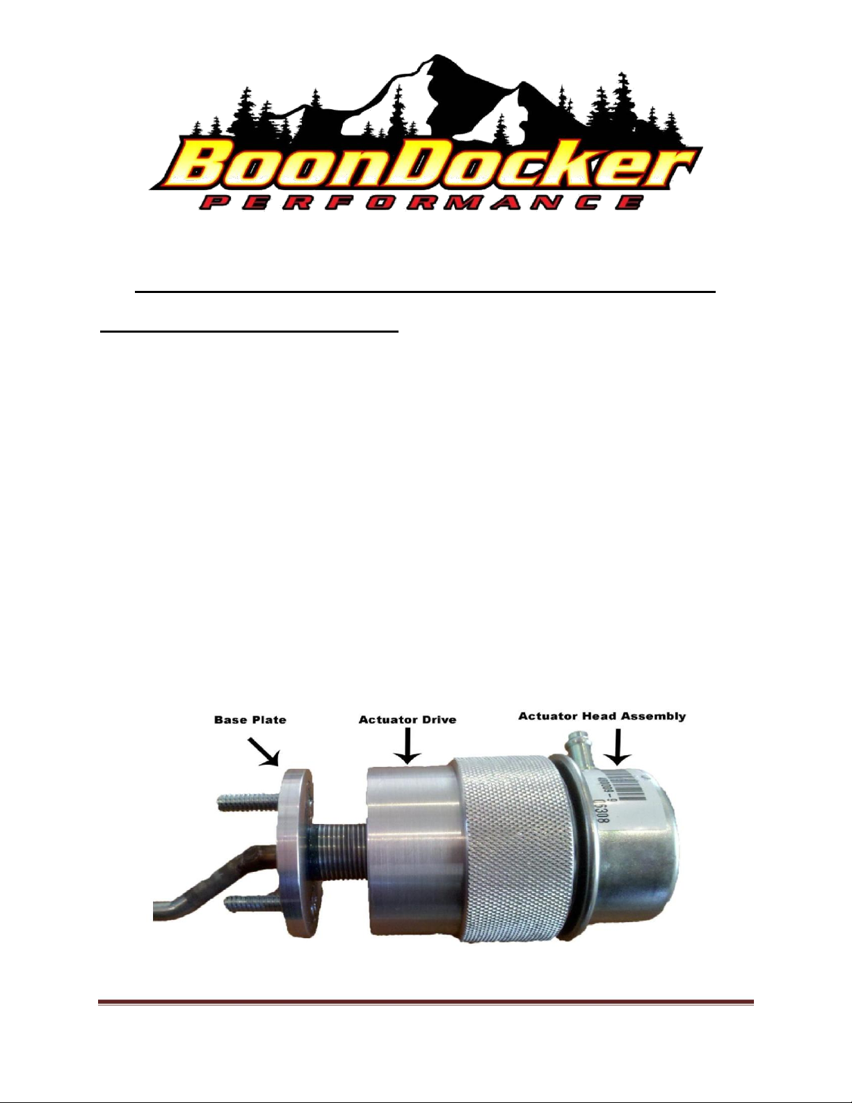
The Adjustable Actuator is comprised of three main components.
1. Actuator Base Plate
2. Actuator Drive/with knurled ring
3. Actuator Head Assembly
Begin your install by removing your existing actuator and attaching the Actuator Base Plate to the
Actuator bracket.
The next step is to thread the Actuator Drive onto the base plate. You will thread it down until it comes
in contact with the base plate.
Next loosen the Actuator head and thread it in two to three turns until you feel slight pressure against the
spring. Note: This will set the minimum boost pressure range. If this is too tight your minimum boost
pressure will be increased.
Then connect your boost line to the vacuum port on the Actuator Head assembly.
Page 1
Page 2
Adjusting your Adjustable Actuator
With the Base Plate bolted to the actuator bracket this is now fixed. With your pressure line on the
Actuator Head assembly it is now basically in a fixed position and cannot turn. To increase your
minimum boost pressure you will turn the knurled Actuator Drive toward the Actuator Head
Assembly, away from the Actuator Base Plate while holding the Actuator Head Assembly. This
increases tension on the spring without changing the rod length to the waste gate.
Note: The overall length of the actuator will not change as the spring pressure is increased.
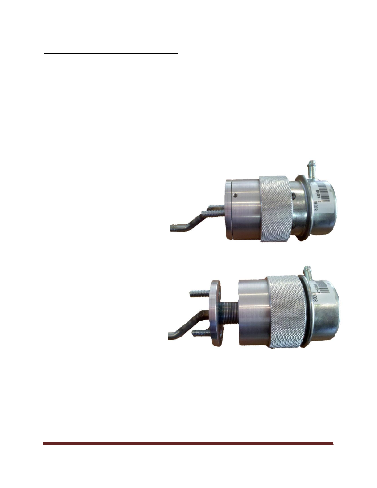
This photo represents an Adjustable
Actuator that is adjusted to a minimum
boost setting.
This photo represents an Adjustable
Actuator that is adjusted to a maximum
boost setting.
Page 2
 Loading...