

Page 1

Boondocker Performance www.boondockers.com 208-542-4411 2010 M8 Turbo Kit Instructions
1
Arctic Cat M8 Pump Gas Turbo Install Instructions
Revised 9/30/2010
Page 2
Boondocker Performance www.boondockers.com 208-542-4411 2010 M8 Turbo Kit Instructions
2
Important Information Before Installing This System:
The 2010 -2011 M8 will require a head modification to run pump gas call Boondocker for
more information.
Before you begin your turbo install, read through these instructions to determine if you are
comfortable installing this system. If not please take it to an experienced mechanic for your
install. It is also a good idea to check the kit contents to verify all parts were provided in the kit
before getting started. This install requires time and patience. Do not rush the installation, if you
have any questions on your installation please contact Boondocker tech support at 1-877-522-
7805.
Step 1: Tear Down
Parts Needed: Tools Needed:
None Basic tool set
Air saw
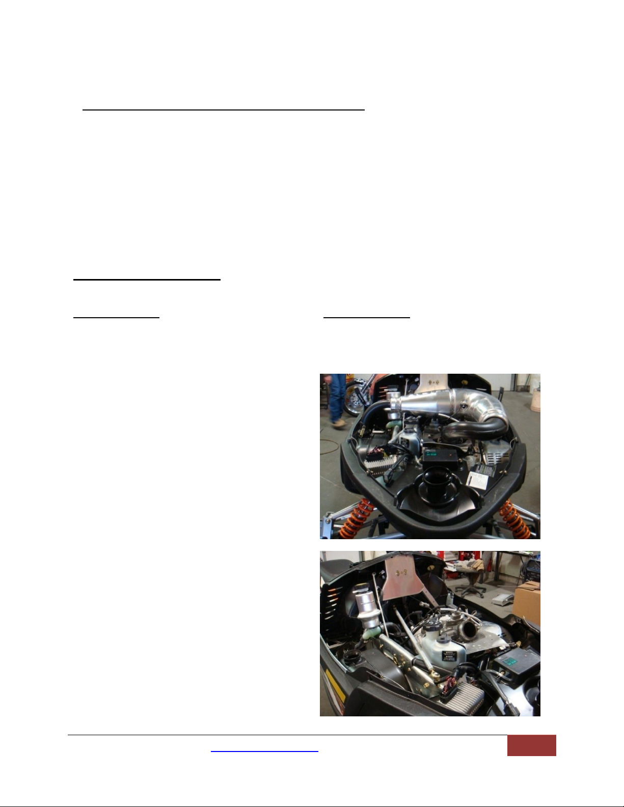
A. Remove hood and side panels
B. Remove pipe and can (remove the
stock rubber mount from the exhaust
can we will need this later).
Revised 9/30/2010
Page 3

BoonDocker Performance www.boondockers.com 208-542-4411 2010 M8 Turbo Kit Instructions
3
C. Remove Y pipe and heat shield. Note: If
you are installing EGT’s now would be the
time to weld on the EGT bungs. Be sure to
mount them 2 ½” from the flange.
D. Remove airbox from nose cone and
remove the plastic boot that connects to
the throttle bodies.
E. Remove the temp sensor from the airbox
and set it aside, you will need this later in
the install.
F. Remove right hand step panel and reverse
beeper.
G. Cut and remove this portion of bulk head
using an air saw, if you do not have an
airsaw you can work this piece loose with
a pair of pliers.
Page 4
BoonDocker Performance www.boondockers.com 208-542-4411 2010 M8 Turbo Kit Instructions
4
Step 2: Mounting The Airbox and ECU
Drill here
Parts Needed: Tools Needed:
2- Machined rings/o-rings installed Drill with 5/16 drill bit
Air temp sensor (removed from stock airbox) Basic tool set
Boondocker airbox Assembly lube
2- self tapping sheet metal screws Silicone
5/16 x ¾” bolt with lock washer
2- Rubber ECU mounts
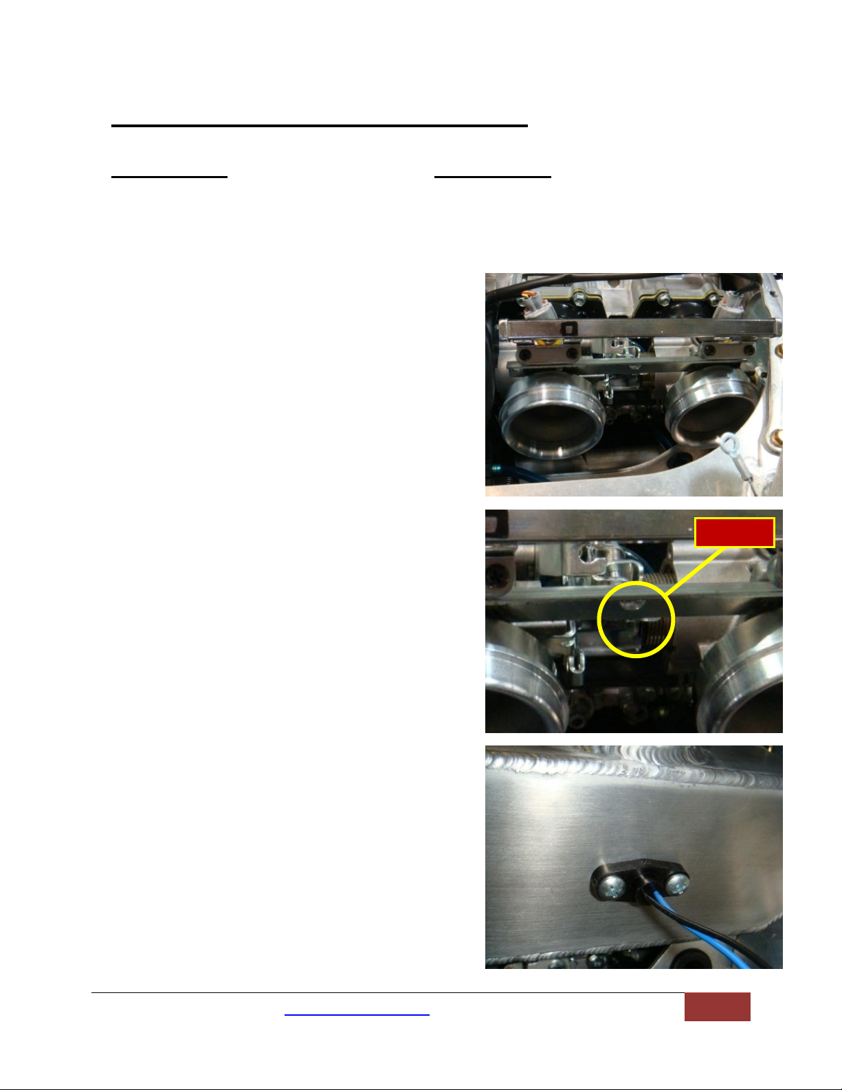
A. Lubricate the o-rings on the machined rings, this
will help ensure a good o-ring seat. Install the
rings to the throttle bodies as shown.
B. Insert the airbox over the machined rings. Mark
and drill a 5/16” hole in the throttle body
support for the airbox mount.
C. Use silicone around the factory temp sensor to
help seal this connection. Be sure not to get any
silicone on the sensor itself. Install the sensor in
the predrilled hole in Boondocker airbox using
the provided self tapping screws.
Page 5
BoonDocker Performance www.boondockers.com 208-542-4411 2010 M8 Turbo Kit Instructions
5
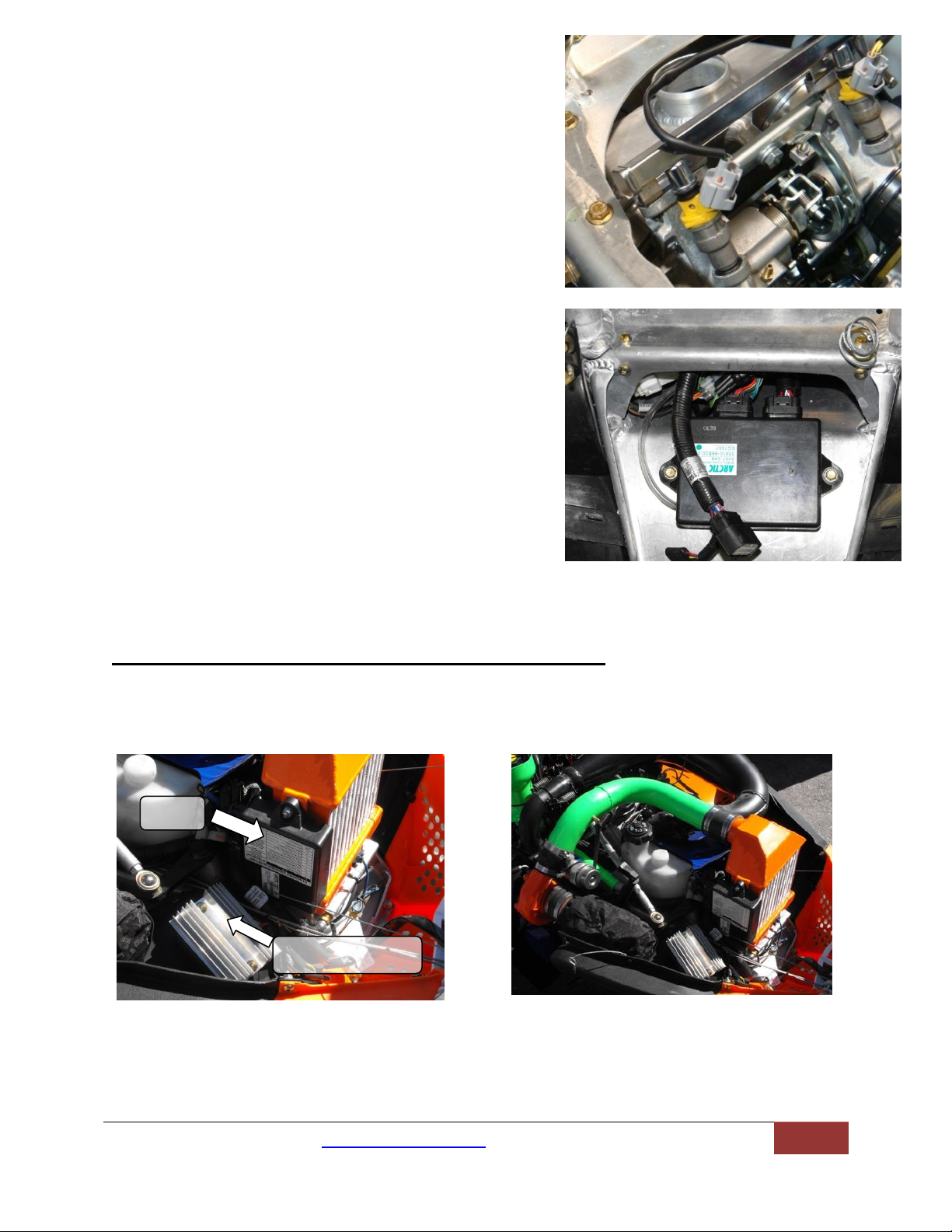
D. Reroute the ECU Harness. Be sure the harness
Voltage regulator
ECU
does not rub on the chassis, this can cause a short
in the wiring,
E. Install the Boondocker airbox and fasten it using
the provided 5/16 x ¾” bolt with lock washer.
F. Relocate the ECU as shown in the picture. Be sure
to mount the ECU far enough forward so that the
connectors plug in without hitting the bulkhead.
Use the factory bolts, and the provided rubber
ECU mounts in between the ECU and bulkhead to
dampen the vibration.(DO NOT
OVERTIGHTEN)
Installing Intercooler (in place of Airbox)
Follow step A-E for Airbox. Relocate the ECU to the side of the Intercooler and re locate the
voltage regulator (see pictures). For wiring fan see Step 6 section B
Page 6
BoonDocker Performance www.boondockers.com 208-542-4411 2010 M8 Turbo Kit Instructions
6
Step 3: Install the Air Density Advantage Kit:
Parts Needed; Tools Needed:
ADA kit bag w/ instructions Basic tool set
Step 4: Installing the Control Box (See Control Box
Instuctions):
Parts Needed: Tools Needed:
Control Box w/instructions Basic tool set
Step 5: Muffler
Parts Needed: Tools Needed:
Muffler Basic tool set
5- 8mm x 25mm Allen head bolts 3” hole saw
Spring tab Die grinder
¼” x ½” bolt with lock nut 2 ¼” hole saw
Muffler support with rubber bumper
2- Aluminum rivets
4- Gold exhaust springs
Turbo oil tank assembly
12” of heat tape
A. Using the provided 12” piece of heat tape.
Wrap the coolant line as shown in picture.
Page 7

BoonDocker Performance www.boondockers.com 208-542-4411 2010 M8 Turbo Kit Instructions
7
B. Using a 3” hole saw make the first cut as shown in picture.
Be sure to trim here for best fit
3”
1 7/8”
Hole center
C. Using a 2 ¼” hole saw make this first cut as shown
D. NOTE: You will have to do additional trimming in the holes to get the muffler to fit, use a die
grinder for this step (see below). You can now fit the muffler inside the foot rest.
Page 8

BoonDocker Performance www.boondockers.com 208-542-4411 2010 M8 Turbo Kit Instructions
8
E. From the inside of the footrest find the center row in the vertical hole pattern and the
hole in the very bottom of the horizontal pattern. Install the spring tab here using the ¼”
x ½” bolt with lock nut as shown in picture.
F. Trim the hole pattern on the front of the foot rest count 6 holes up on the middle vertical
hole pattern and 5 holes up on the right vertical hole pattern. Fasten the muffler support
bumper here using the 2 aluminum rivets as shown in picture.
G. Trim 3 rounded spots on the foot rest as shown and mount the reverse beeper.
H. Place a bead of high temp silicone around the muffler flange as shown, reinstall to turbo.
I. Install the 5 hole muffler flange to the turbo exhaust housing using the 5- 8mm x25mm
Allen heat bolts. Install the 4 gold springs as shown.
.
Page 9

BoonDocker Performance www.boondockers.com 208-542-4411 2010 M8 Turbo Kit Instructions
9
J. Turn the sled on its side and install the heat deflector plate as shown in picture, fasten
Install rubber grommet from
stock exhaust.
using the factory bolts
Step 6: Turbo/Oil Tank
Assembly Installations
Parts Needed: Tools Needed:
Turbo/Oil Tank Assembly Basic Tool Kit
A. Mount the oil tank/ turbo assembly to the sled using the stock exhaust can mounts as
shown in picture.
Page 10

BoonDocker Performance www.boondockers.com 208-542-4411 2010 M8 Turbo Kit Instructions
10
B. Wiring your oil pump. Use the Voltage Regulator Power Adapter (supplied in the kit,
see picture), plug in between the chassis harness and voltage regulator (see picture). If
you have an Intercooler with fan you will connect here also.
Step 7: Installing Water Lines
Parts Needed: Tools Needed:
2-Banjo style water fittings 1 @ 17” 1 @ 19’’ Basic tool set
2- Bolts for Banjo fittings 4- Copper washers
1-¼” x ¼” barbed fitting
T20 torx head bit.
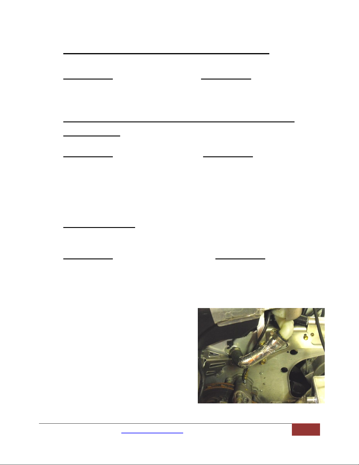
A. To route the water lines tilt the sled on its side
and remove the belly plate using a T20 torx head
bit.
B. Locate the factory water line that runs from the
throttle bodies to the back of the motor. Pinch the
factory water line with a pair of vise grips or
other clamping pliers and remove the factory
clamp Note: you may have to rotate the clamp to
gain access to
The worm drive fastener on the hose clamp.
Page 11

BoonDocker Performance www.boondockers.com 208-542-4411 2010 M8 Turbo Kit Instructions
11
C. Connect the 19” water line on the turbo charger
to the back of the motor and fasten with the
factory clamp
D. Trim the protective plastic cover right before the
clamp. We will use this later.
E. Route the 17” water line from the turbo to the
stock water line that you just pinched off. Trim
the factory water line to proper length and
connect the factory water line to the 17” turbo
water line using the supplied ¼” barb and fasten
with the 2 #4 hose clamps provided in the kit (as
shown in picture).
\
C. Install the piece of trimmed plastic sleeving on
the upper side of the water line, this will keep
the hose from rubbing on any sharp edges (see
picture).
Page 12

BoonDocker Performance www.boondockers.com 208-542-4411 2010 M8 Turbo Kit Instructions
12
Step:8 Fuel System
Parts Needed: Tools Needed:
Fuel regulator fitting Basic tool set
2- 1/8” NPT x 1/8” PTC 90 Vise
41” of 1/8” poly line Drill w/ 5/16” drill bit
Bulkhead fitting with 1/8” push to connect Nut driver
5/16 nylon lock nut
1/4 “ flat washer
4- 8” cable zip ties
7” of clear 3/16” tubing
Boondocker airbox
A. Disconnect and remove the electrical connector, fuel
line, brass fitting and the nut shown in picture, then
remove the factory fuel pump from the gas tank.
B. Locate the brass fuel regulator fitting and using a
9/16” socket press the fitting on the stock fuel
regulator using a vise as shown in picture.
C. Thread the 1/8 push to connect 90 into the copper
cap as shown in picture
D. Reinstall the fuel pump in gas tank.
E. Find a flat surface on the fuel tank to mount the
bulkhead fitting. Drill a 5/16” hole and install the
bulkhead union in gas tank. Fasten the bulkhead
fitting using the provided 5/16 lock nut and ¼” tighten using a nut driver. IMPORTANT:
Do not over tighten this fitting it will break.
Page 13

BoonDocker Performance www.boondockers.com 208-542-4411 2010 M8 Turbo Kit Instructions
13
F. Install the 90 degree push to connect fitting in
the air box as shown
G. Locate the 41” of 1/8” black poly and route the
poly line to the bulkhead fitting following the
throttle cable as shown. Insert the 7” of clear
tubing onto the poly line as shown and connect
to airbox. Note: be sure to avoid sharp edges,
possible melting and kinking the 3/16” hose.
H. Push the poly line through the bulkhead fitting
and connect it to the fitting on the copper cap we
installed in part C.
Page 14

BoonDocker Performance www.boondockers.com 208-542-4411 2010 M8 Turbo Kit Instructions
14
Step 9:Exhaust Pipe
Parts Needed: Tools Needed:
Air saw or band saw
4- 8mm non Nylon lock nuts Welder
Stock pipe Basic tool kit
Boondocker turbo inlet Grinder or sand paper
4- 8mm x 25mm bolts
A. Remove stock heat shield from pipe.
B. Cut the exhaust pipe right before the weld as
shown in picture. You will also need to grind
about 1.5” inches off the factory weld of the
pipe as shown in picture.
C. Sand the end of the pipe and the inlet for a
clean weld on the pipe
D. Bolt the turbo inlet to the exhaust housing on
the turbo as shown using the provided 8mm
bolts and nuts Note: the exhaust housing side of
the turbo should still be loose, this will allow
you to rotate the housing as needed to fit the
exhaust pipe.
Page 15

BoonDocker Performance www.boondockers.com 208-542-4411 2010 M8 Turbo Kit Instructions
15
E. Reinstall the bottom heat shield on the pipe and
install the exhaust pipe as shown in picture Be
sure to spring the pipe in place to ensure proper
placement (use factory springs).
F. We are now ready to weld the inlet to the exhaust
pipe. Either mark the inlet and pipe with a
permanent marker and remove pipe to tack and
weld, or If you plan on tacking the inlet to the pipe
on the sled, be sure to disconnect the ECU failure
to follow this step will result in damage to your
ECU. Remove pipe and finish the weld.
NOTE: Do not reinstall the exhaust pipe until you
complete step 9.
Page 16

BoonDocker Performance www.boondockers.com 208-542-4411 2010 M8 Turbo Kit Instructions
16
Step 10: Exhaust Pipe Final Install
Parts Needed: Tools Needed:
Air saw or band saw
4- High tension exhaust spring Basic tool kit
4- 8mm x 25mm bolts Spring tool
4- 8mm top lock nuts Black high temp spray paint
4 Hole exhaust gasket (packaged in turbo box)
Exhaust Pipe with heat shield
Factory heat shield
A. For a cleaner look, paint the welded inlet on the
exhaust pipe with a black high temp spray paint.
B. Reinstall the factory heat shield on exhaust pipe.
C. Using an air saw or band saw trim the exhaust heat
shield as shown in picture
D. Reinstall the heat shield to the sled
E. To save you a headache install the 2 high tension
exhaust springs on the right side of the pipe first,
this allows you to use the exhaust pipe to torque the
springs instead of a spring puller. Be sure to install
the short hook onto the pipe side and the long side
of the spring to the Y pipe.
F. Be sure to add the 4-hole gasket on the turbo side
of the pipe. Fasten this connection using the
provided 8mm bolts with lock nuts.
G. Install the remaining high tension exhaust springs
Page 17

BoonDocker Performance www.boondockers.com 208-542-4411 2010 M8 Turbo Kit Instructions
17
Step 12: Charge Tube ( If Intercooler kit same process)
Parts Needed: Tools Needed:
2” x 3” black silicone Basic tool set
2” x 2” black silicone
4- Size 32 hose clamps
6.5” of 3/16” hose
2- 4” zip ties
A. Install 2” x 2” black silicone to the Boondocker
airbox and loosely place 2 size 32 hose clamps over
the silicone.
B. Install 2” x 3” black silicone to the turbo charger
and loosely place 2 size 32 hose clamps over the
silicone.
C. Insert the charge tube into the 2 silicone pieces as
shown
D. Tighten all 4 size 32 hose clamps
E. Route the 6.5” piece of 3/16” tubing from the
actuator to the barbed fitting on the charge tube.
F. Zip tie these 2 connections.
Page 18

BoonDocker Performance www.boondockers.com 208-542-4411 2010 M8 Turbo Kit Instructions
18
Step 13: Final Touches
Parts Needed: Tools Needed:
Snorkel filter Basic tool set
Oil tube w/dipstick Assembly lube
A. Fill oil tank with 16oz of synthetic 2 stroke
engine oil IMPORTANT: start the sled to
make sure the oil pump is working before
installing it to the turbo.
B. Install the oil hose to the top of the turbo as
shown
C. Clean up and zip tie all hoses.
D. Using the provided size 48 hose clamp, fasten
the snorkel filter to the turbo inlet as shown.
E. Well you did it, good job. Replace the hood
and side panels, oh yeah, and don’t forget to
hold on!!! Thanks for choosing Boondocker
Performance Products.
 Loading...