

Page 1

Customer Reference Manual
Model M3628PUT
Portable Ultracapacitor Tester
Page 2

Bonitron, Inc.
Bonitron, Inc.
Nashville, TN
An industry leader in providing solutions for AC drives.
ABOUT BONITRON
Bonitron designs and manufactures quality industrial electronics that improve the reliability of
processes and variable frequency drives worldwide. With products in numerous industries, and
an educated and experienced team of engineers, Bonitron has seen thousands of products
engineered since 1962 and welcomes custom applications.
With engineering, production, and testing all in the same facility, Bonitron is able to ensure its
products are of the utmost quality and ready to be applied to your application.
The Bonitron engineering team has the background and expertise necessary to design,
develop, and manufacture the quality industrial electronic systems demanded in today’s market.
A strong academic background supported by continuing education is complemented by many
years of hands-on field experience. A clear advantage Bonitron has over many competitors is
combined on-site engineering labs and manufacturing facilities, which allows the engineering
team to have immediate access to testing and manufacturing. This not only saves time during
prototype development, but also is essential to providing only the highest quality products.
The sales and marketing teams work closely with engineering to provide up-to-date information
and provide remarkable customer support to make sure you receive the best solution for your
application. Thanks to this combination of quality products and superior customer support,
Bonitron has products installed in critical applications worldwide.
2
Page 3

Bonitron, Inc.
Undervoltage Solutions
Overvoltage Solutions
Uninterruptible Power for Drives
(DC Bus Ride-Thru)
Voltage Regulators
Chargers and Dischargers
Energy Storage
Braking Transistors
Braking Resistors
Transistor/Resistor Combo
Line Regeneration
Dynamic Braking for Servo Drives
Common Bus Solutions
Portable Maintenance Solutions
Single Phase Power Supplies
3-Phase Power Supplies
Common Bus Diodes
Capacitor Formers
Capacitor Testers
Power Quality Solutions
Green Solutions
12 and 18 Pulse Kits
Line Regeneration
AC DRIVE OPTIONS
In 1975, Bonitron began working with AC inverter drive specialists at synthetic fiber plants to
develop speed control systems that could be interfaced with their plant process computers.
Ever since, Bonitron has developed AC drive options that solve application issues associated
with modern AC variable frequency drives and aid in reducing drive faults. Below is a sampling
of Bonitron’s current product offering.
WORLD CLASS PRODUCTS
3
Page 4

M3628PUT
1. INTRODUCTION ..........................................................................................................................7
1.1. Who Should Use ........................................................................................................................ 7
1.2. Purpose and Scope..................................................................................................................... 7
1.3. Manual Version and Change Record ......................................................................................... 7
Figure 1-1: M3628PUT ........................................................................................................................ 7
1.4. Symbol Conventions Used in this Manual and on Equipment .................................................. 8
2. PRODUCT DESCRIPTION / FEATURES ........................................................................................9
2.1. Related Products ........................................................................................................................ 9
2.2. Part Number Breakdown ......................................................................................................... 10
Figure 2-1: Example of Part Number Breakdown .............................................................................. 10
2.3. General Specifications ............................................................................................................. 10
Table 2-1: General Specifications Table ............................................................................................ 10
2.4. General Precautions and Safety Warnings .............................................................................. 11
3. INSTALLATION INSTRUCTIONS ................................................................................................13
3.1. Environment ............................................................................................................................ 13
3.2. Wiring and Customer Connections ......................................................................................... 13
3.2.1. Power Wiring .............................................................................................................................. 13
Figure 3-1: M3628PUT Faceplate ...................................................................................................... 13
3.2.2. Source Considerations ................................................................................................................. 14
3.2.3. Load Considerations .................................................................................................................... 14
4. OPERATION ..............................................................................................................................15
4.1. Functional Description ............................................................................................................ 15
4.2. Features ............................................................................................................................. 15
4.2.1. AC Power Input Connector ......................................................................................................... 15
4.2.2. DC Output Connectors ................................................................................................................ 15
4.2.3. Display ........................................................................................................................................ 15
4.2.4. Interface Buttons ......................................................................................................................... 15
4.2.5. LEDs ............................................................................................................................................ 15
4.2.6. Abort Button ................................................................................................................................ 15
4.2.7. Voltage Present Indicator ............................................................................................................ 16
4.2.8. Fuse ............................................................................................................................................. 16
4.2.9. Power Switch / Circuit Breaker ................................................................................................... 16
4.3. Screens & Menu Navigation ................................................................................................... 16
4.3.1. Main Menu .................................................................................................................................. 16
Figure 4-1: M3628PUT Charging Profile ........................................................................................... 17
Figure 4-2: M3628PUT Interface Screen Tree ................................................................................... 18
4.4. Faults ............................................................................................................................. 20
4.4.1. Overtemp ..................................................................................................................................... 20
4.4.2. Communication Loss ................................................................................................................... 20
4.4.3. Reverse Bias ................................................................................................................................ 20
4.4.4. Fuse Loss ..................................................................................................................................... 20
4.4.5. Relay Failure ............................................................................................................................... 20
4.4.6. Short IGBT ................................................................ ................................................................ .. 20
5. MAINTENANCE AND TROUBLESHOOTING ...............................................................................21
5.1. Maintenance Items .................................................................................................................. 21
5.2. Troubleshooting....................................................................................................................... 21
Table 5-1: Troubleshooting ................................................................................................................ 21
5.3. Technical Help ........................................................................................................................ 22
6. ENGINEERING DATA ................................................................................................................23
4
Page 5

Table of Contents
6.1. Ratings Chart ........................................................................................................................... 23
Table 6-1: Ratings Chart ..................................................................................................................... 23
6.2. Dimensional Drawing .............................................................................................................. 23
Figure 6-1:M3628PUT Dimensions ................................................................................................... 23
6.3. Block Diagram ........................................................................................................................ 23
Figure 6-2: Block Diagram ................................................................................................ ................. 23
7. APPENDIX .................................................................................................................................25
7.1. Application Notes .................................................................................................................... 25
7.1.1. Typical Capacitor Bank Forming / Testing Procedure ................................................................ 25
5
Page 6

M3628PUT
This page intentionally left blank
6
Page 7
User’s Manual
1. INTRODUCTION
1.1. WHO SHOULD USE
This manual is intended for use by trained personnel responsible for maintaining or
testing Ultracapacitors.
Please keep this manual for future reference.
1.2. PURPOSE AND SCOPE
This manual is a user’s guide for the Model M3628PUT. It will provide the user with
the necessary information to successfully connect and operate the M3628PUT.
In the event of any conflict between this document and any publication and/or
documentation related to any associated hardware (capacitor bank, etc.), the latter
shall have precedence.
1.3. MANUAL VERSION AND CHANGE RECORD
Rev 00 is the original printing of the M3628PUT manual.
The Example of the Part Number Breakdown was changed in Rev 00a.
Input Voltage options were added in Rev 01.
The manual template was updated in Rev01a.
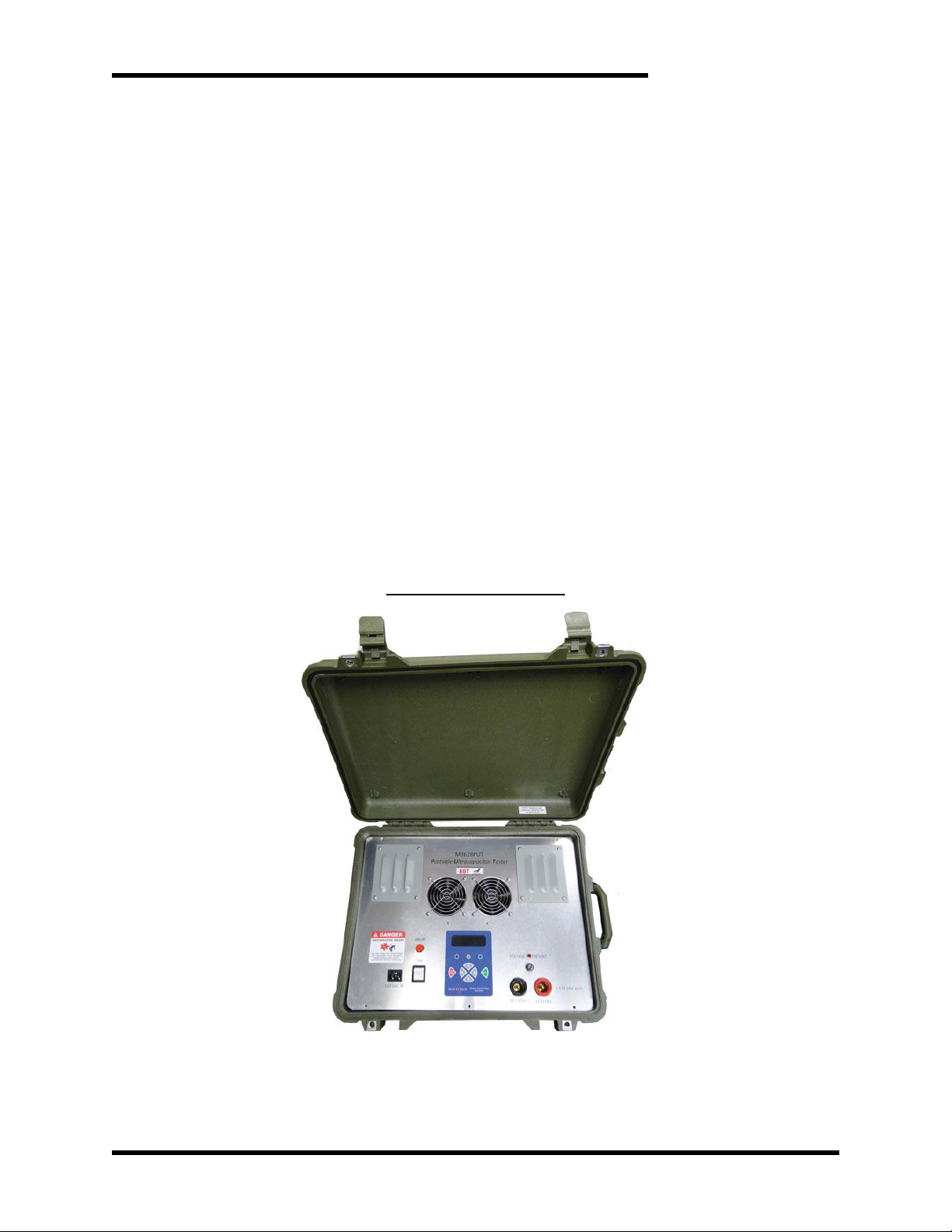
Figure 1-1: M3628PUT
7
Page 8
M3628PUT
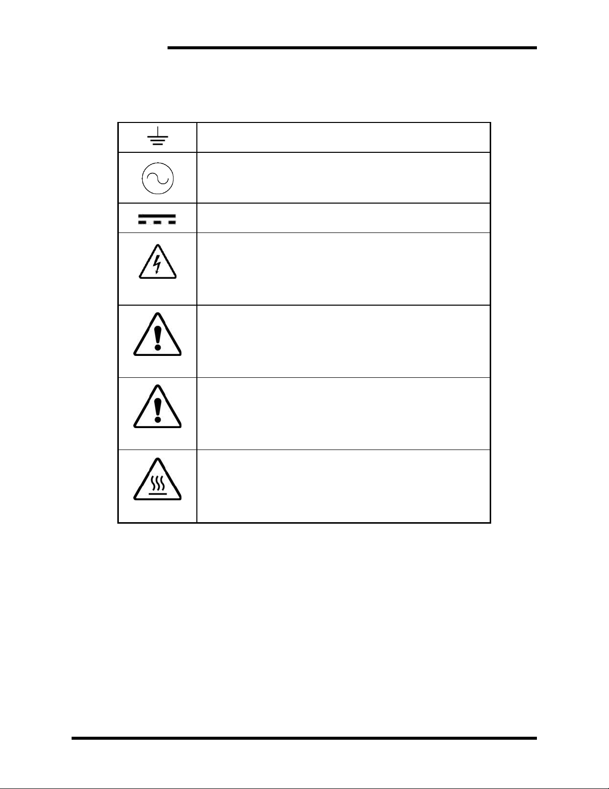
Earth Ground or Protective Earth
AC Voltage
DC Voltage
DANGER!
Electrical Hazard - Identifies a statement that indicates a shock
or electrocution hazard that must be avoided.
DANGER!
DANGER: Identifies information about practices or
circumstances that can lead to personal injury or death,
property damage, or economic loss.
CAUTION!
CAUTION: Identifies information about practices or
circumstances that can lead to property damage, or economic
loss. Attentions help you identify a potential hazard, avoid a
hazard, and recognize the consequences.
CAUTION!
Heat or burn hazard - Identifies a statement regarding heat
production or a burn hazard that should be avoided.
1.4. SYMBOL CONVENTIONS USED IN THIS MANUAL AND ON
EQUIPMENT
8
Page 9

User’s Manual
2. PRODUCT DESCRIPTION / FEATURES
The M3628PUT is designed for testing of ultracapacitors. As ultracapacitors age and
wear, their capacitance decreases, and their ESR increases. This can result in
decreased system performance, and ultimately, process failure. Measurement of an
ultracapacitor's capacitance and ESR can help avoid expensive preemptive
replacement.
The M3628PUT is a portable digitally-controlled capacitor tester. The digital interface
allows the user to charge an attached ultracapacitor to a specified voltage, and then
discharge the capacitor. After discharge is complete, the display will show the
capacitance and ESR of the ultracapacitor.
2.1. RELATED PRODUCTS
M3528 ULTRACAPACITOR/ BATTERY CHARGER
The M3528 Charger can charge strings of batteries or ultracapacitors to voltages
required for industrial and commercial applications. AC or DC input is available,
along with separate float and equalization charge levels. The charger is current
limited, and designed for use in integrated storage and backup systems, but can also
be used in bench or mobile systems.
M3628 ULTRACAPACITOR DISCHARGE CONTROLLER
Large capacitor banks store huge amounts of energy, and can be a hazard when
systems are shut down for system maintenance. The M3628 system discharges
capacitor banks to safe working levels quickly, allowing work on the system to begin
in seconds, rather than hours.
M3628PCF PORTABLE CAPACITOR FORMER
The M3628 Portable Capacitor Former can be used to charge or discharge capacitor
banks as large as 50 kJ. The output voltage is manually variable between 0 and 900
VDC, and the system is capable of supplying 1 ADC continuously. The unit can be
used for reforming disused capacitors.
M3628PCT PORTABLE CAPACITOR TESTER
The M3628 Portable Capacitor Tester can be used to charge, discharge and
measure capacitor banks as large as 300 kJ. The output voltage can be set by
digital control to between 0 and 800 VDC, and the system is capable of supplying 1
ADC up to 450 VDC. When discharging, the unit times the discharge and gives a
capacitance value for capacitor banks between 2200 uF and 1F. The unit can also
be used for automatic reforming of disused capacitors.
9
Page 10
M3628PUT
PARAMETER
SPECIFICATION
Input Voltage
110-120VAC, 220-240VAC, 1ø
Output Voltage
0-130VDC
Output Current
1-7ADC
Minimum Load Capacitance
1 Farad
Maximum Load Energy
500 kJ
Minimum Cycle Voltage
5V
Controls
Six display soft keys
Abort button
Display
Four line, eighty character LCD (4x20)
Unit Size (H x W x D)
18.00" x 22.00" x 10.50"
Weight
50 lbs.
Storage Temp
-20°C to +65°C
Humidity
Below 90% non-condensing
Atmosphere
Free of corrosive gas and dust
M3628PUT
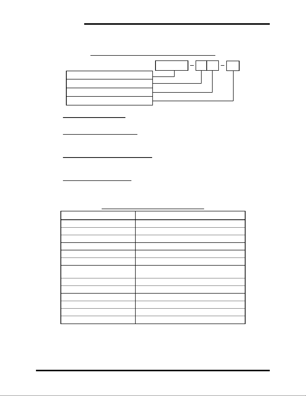
U
07
BASE MODEL NUMBER
OUTPUT VOLTAGE
MAXIMUM OUTPUT CURRENT
INPUT VOLTAGE
2.2. PART NUMBER BREAKDOWN
Figure 2-1: Example of Part Number Breakdown
BASE MODEL NUMBER
The Base Model Number for all Portable Ultracapacitor Testers is M3628PUT.
OUTPUT VOLTAGE RATING
The Maximum Output Voltage Rating indicates the DC output voltage the unit can
supply. At present there is only a U model.
MAX OUTPUT CURRENT RATING
The Maximum Output Current rating indicates the maximum DC current the unit can
supply at its maximum voltage.
INPUT VOLTAGE RATING
This indicates the input voltage for the unit.
2.3. GENERAL SPECIFICATIONS
Table 2-1: General Specifications Table
10
Page 11
User’s Manual
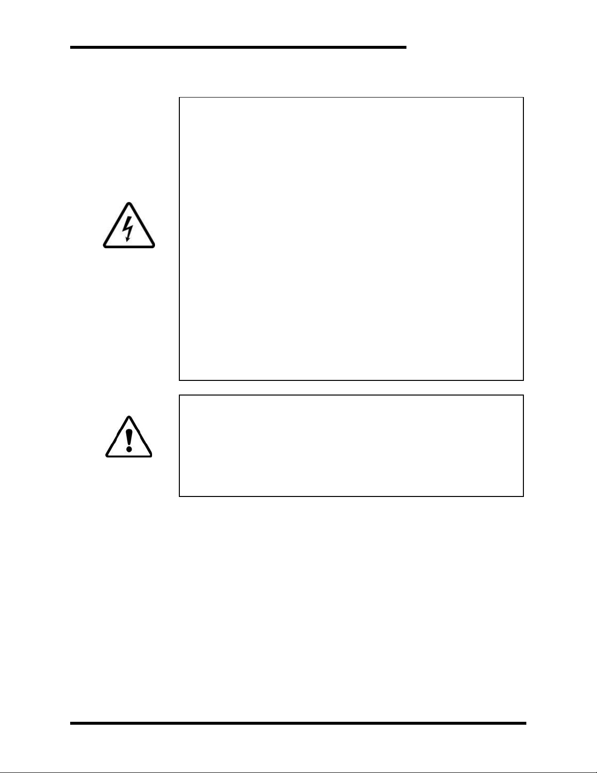
ELECTROCUTION
HAZARD!
THIS UNIT PRODUCES VOLTAGES CAPABLE OF CAUSING INJURY
OR DEATH!
FOR USE BY QUALIFIED AND TRAINED PERSONNEL ONLY!
IMPROPER OPERATION OF THE PRODUCT OR
IGNORING THESE WARNINGS MAY RESULT IN
SERIOUS BODILY INJURY OR DEATH!
BEFORE CONNECTING THE M3628PUT TO A CAPACITOR BANK,
ENSURE THAT THE BANK IS FULLY DISCHARGED BY CHECKING
WITH A VOLTMETER.
CONNECTING THE M3628PUT’S VOLTAGE OUTPUT TO A LOAD
WITH THE POLARITY REVERSED CAN CAUSE DAMAGE TO YOUR
EQUIPMENT AND POTENTIALLY CREATE A FIRE OR EXPLOSION
HAZARD, THREATENING LIVES. ENSURE THAT THE POSITIVE
AND NEGATIVE TERMINALS ON BOTH THE SOURCE AND LOAD
ARE POSITIVELY IDENTIFIED AND CORRECTLY CONNECTED
BEFORE OPERATION.
NEVER OPERATE THIS PRODUCT WITH THE ENCLOSURE COVER
REMOVED.
DANGER!
NEVER ATTEMPT TO SERVICE THIS PRODUCT.
CERTAIN PARTS INSIDE THIS PRODUCT MAY GET HOT DURING
OPERATION.
BEFORE CONNECTING THIS DEVICE TO ANY OTHER PRODUCT,
BE SURE TO REVIEW ALL DOCUMENTATION OF THAT PRODUCT
FOR PERTINENT SAFETY PRECAUTIONS.
2.4. GENERAL PRECAUTIONS AND SAFETY WARNINGS
ANY QUESTIONS AS TO APPLICATION, INSTALLATION, OR SERVICE
SAFETY SHOULD BE DIRECTED TO THE EQUIPMENT SUPPLIER.
11
Page 12

M3628PUT
This page intentionally left blank
12
Page 13
User’s Manual
WARNING!
Attaching the unit to an AC input voltage other than that specified for your
unit may cause improper operation or damage!
ABORT
ON
OFF
110 VAC IN
NEGATIVE POSITIVE
VOLTAGE PRESENT
0-130 VDC OUT
M3628PUT
PORTABLE ULTRACAPACITOR TESTER
Dwg: 120270 Rev: 20120726
3. INSTALLATION INSTRUCTIONS
3.1. ENVIRONMENT
While closed, the M3628PUT is water, dust, and crush resistant. When open and in
operation, the unit should be used only in dry, clean areas. Ensure that the interior
of the unit casing is kept dry.
3.2. WIRING AND CUSTOMER CONNECTIONS
3.2.1. POWER WIRING
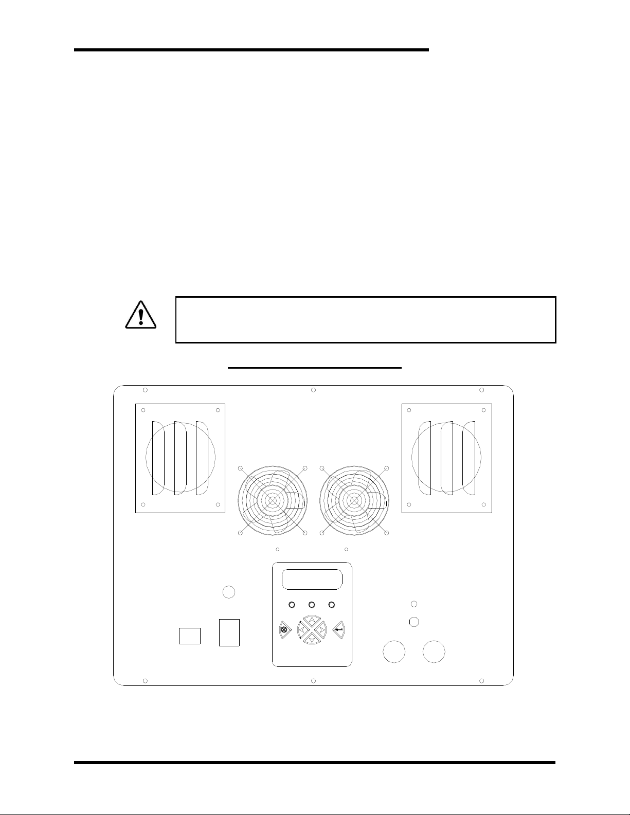
The Power Input connector accepts 50-60Hz AC from the included standard
C13 power cable. The DC Output connectors supply DC voltage at the
user-selected level via a pair of high-current connectors. Output leads can
be constructed as needed. The unit should be powered ON before
connecting to a load, as the unit is in discharge mode when powered off.
Figure 3-1: M3628PUT Faceplate
13
Page 14

M3628PUT
WARNING!
Drawing current from a capacitor in excess of its maximum rated current
can cause the capacitor to overheat and explode! Confirm the maximum
current rating of the capacitor before charging or discharging.
3.2.2. SOURCE CONSIDERATIONS
3.2.3. LOAD CONSIDERATIONS
It is important to only connect this unit to a source that meets the specified
voltage and current requirements.
The source must be capable of supplying 14A @110VAC or 7A @ 220VAC
under normal operating conditions.
Failure to meet the minimum current requirement may result in improper
operation.
Connecting the unit to an input voltage other than that specified on the unit
faceplate may also result in improper operation or damage to the unit.
To ensure the most accurate possible measurements, the capacitor under
test should be charged to its full rated voltage. Note that the M3628PUT will
discharge the attached load capacitor to 2VDC. This unit is thus not
recommended for use on ultracapacitors rated at less than 5VDC.
Before charging or discharging an attached capacitor, ensure that the
capacitor is capable of safely sourcing the current which will be drawn by
the .6 ohm discharge resistor at the desired charge voltage. I=V/R.
14
Page 15

User’s Manual
4. OPERATION
4.1. FUNCTIONAL DESCRIPTION
The M3628PUT is a digitally controlled DC supply capable of sourcing between 1
and 7 amps at between 0 and 130VDC. The unit is powered by standard 50-60 Hz
AC. The output voltage is controlled by the digital interface panel on the front of the
unit. The unit is capable of safely charging and discharging connected capacitors. It
is also capable of executing a pre-programmed charging profile, with defined step
voltages and hold times. When a capacitor is discharged, the unit will calculate and
display the capacitance and ESR of the capacitor. An Abort button is present in case
of user error when selecting charge voltage. The unit automatically enters discharge
mode when powered off.
4.2. FEATURES
4.2.1. AC POWER INPUT CONNECTOR
The M3628PUT is equipped with a standard IEC C14 connector for input
power. This connector mates with a standard C13 cable, commonly used
with desktop computers, to provide power to the unit.
4.2.2. DC OUTPUT CONNECTORS
Two high-current jacks provide the user with DC output voltage between 0
and 130VDC, and provide a discharge path for the current from the
capacitor being tested. Cables are included, and can be constructed as
desired.
4.2.3. DISPLAY
The digital display presents the user with information about the present
status of the system, including the output voltage and current. The display
also presents the user with options to control system operation, including
charging and discharging attached capacitors.
4.2.4. INTERFACE BUTTONS
The function of each button depends on the active screen. For menu
screens, enter selects a menu option, while cancel moves back to the
previous screen. Up and down move the menu curser. On screens where
numbers are input by the user, the left and right buttons move the cursor,
while the up and down buttons change the selected digit. Enter stores the
present value, while cancel undoes any changes. On some screens,
certain buttons may perform no function.
4.2.5. LEDS
Three LEDs indicate the present status of the PUT. Red indicates a fault
condition. Yellow indicates that the unit is presently charging or discharging.
Green indicates that the unit has power.
4.2.6. ABORT BUTTON
There is a red Abort button on the face of the unit. This button will cause
the system to immediately switch to discharge mode, regardless of the
15
Page 16

M3628PUT
WARNING!
Do not use this light as an indication that the output is safe to work on!
Always check the output with a working voltmeter before servicing
equipment, as the lamp may be malfunctioning!
ELECTROCUTION HAZARD! This unit produces dangerous levels of
voltage that can cause injury or death. Always follow safety protocols
when working with high voltages!
4.2.7. VOLTAGE PRESENT INDICATOR
4.2.8. FUSE
present system activity. In the event the unit is accidentally set to charge to
a higher voltage than is safe for one load, this button should be pressed
immediately.
A red light indicates that there is an unsafe voltage on the DC output of the
unit. Do not touch the output connectors or the attached equipment while
this light is on, as electric shock will result.
This fuse is in the charging output of the PUT. If the fuse fails, power down
the unit, and replace it with the same fuse. (see Section 5) Do not replace
the fuse while the system is live!
4.2.9. POWER SWITCH / CIRCUIT BREAKER
The Power Switch also acts as a circuit breaker to protect from overload
conditions. If the breaker is tripped, you can reset it by simply turning the
switch back on.
NOTE: When switched OFF, the unit is in Discharge mode.
4.3. SCREENS & MENU NAVIGATION
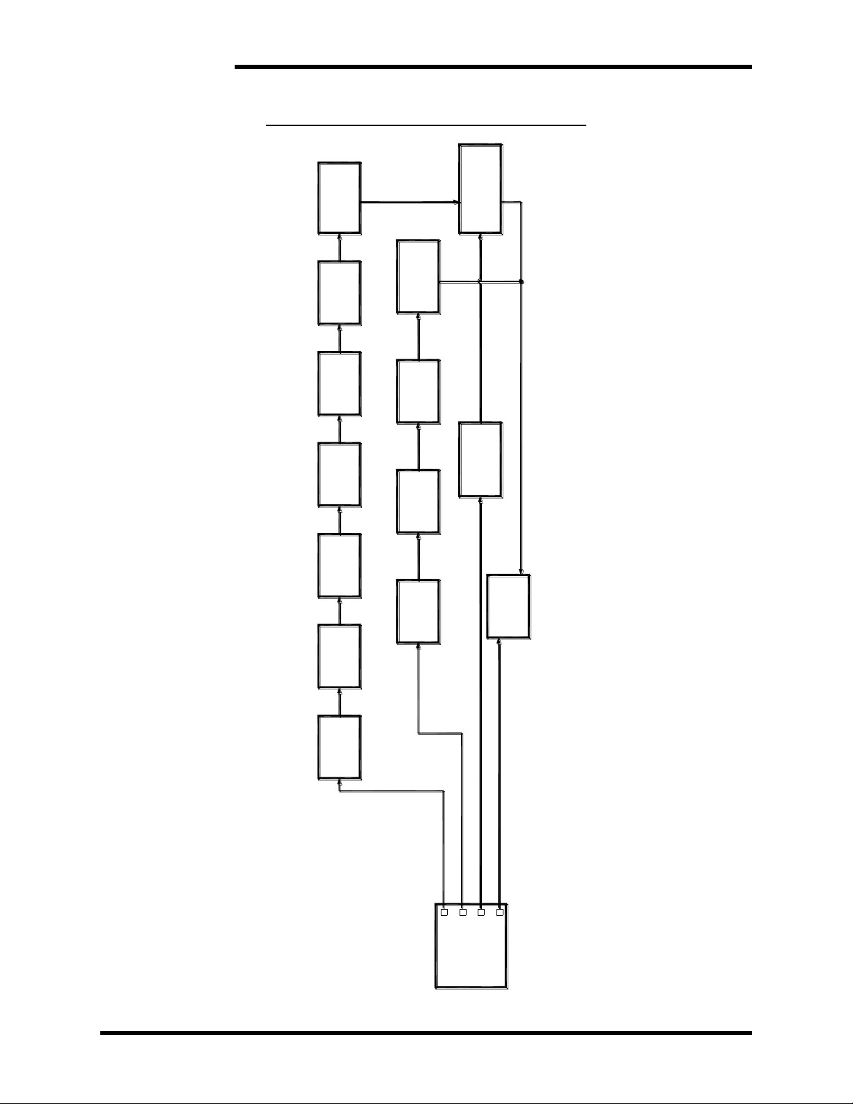
Many screens are menus allowing access to other screens, or lists presenting a
number of options. The presently selected item on the menu is indicated by a ‘>’
character. This selection indicator is moved using the up and down buttons. If a line
on the menu represents another screen, that screen may be accessed with the enter
key. The cancel button will typically return the display to the parent screen.
4.3.1. MAIN MENU
The Charging Profile, Single Charge, Discharge, and Previous Results
screens may be accessed from the Main Menu.
4.3.1.1. CHARGING PROFILE
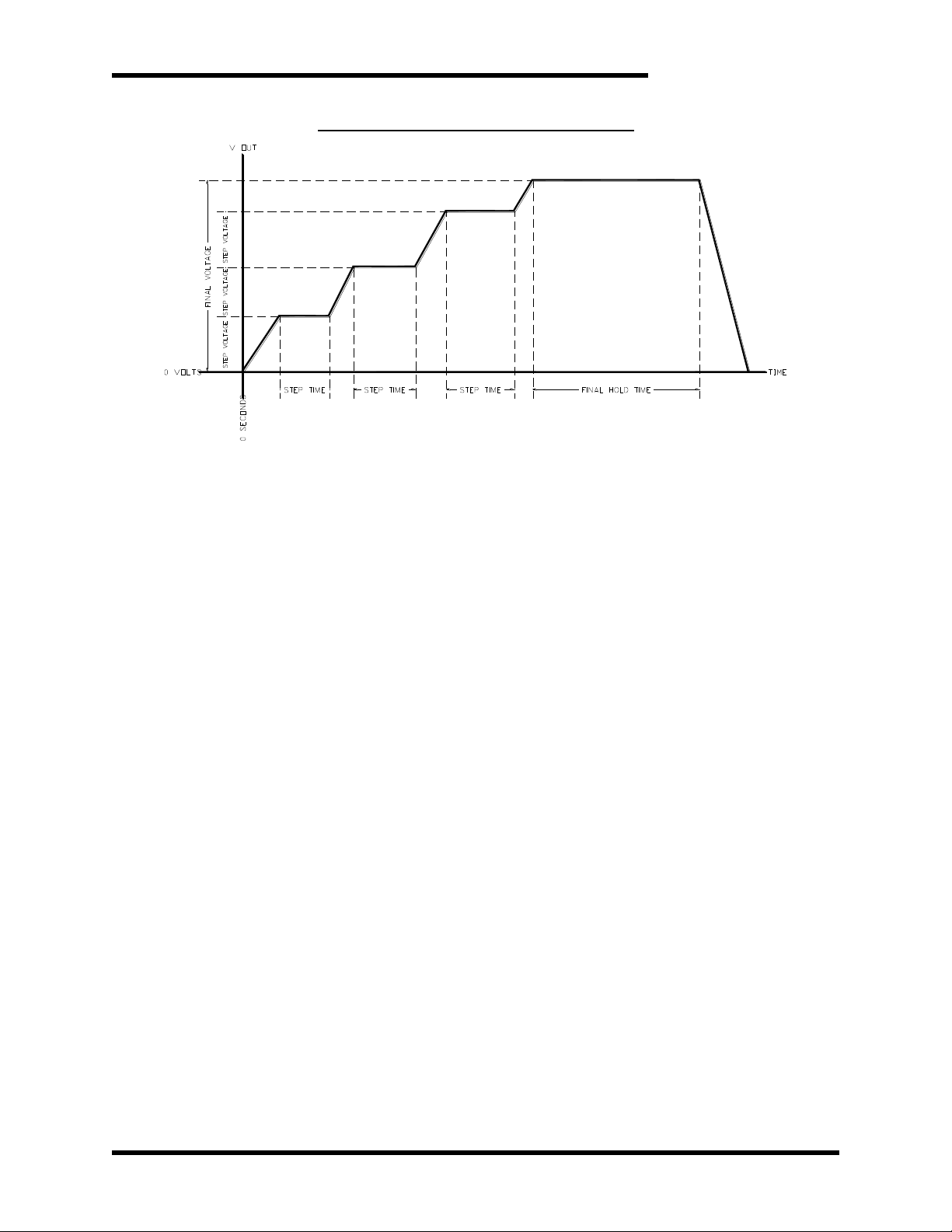
From this selection, the user may input the variables necessary to
execute an automatic Charging Profile. A charging profile charges the
capacitor in steps, each step a specified voltage apart. When each step
voltage is reached, the load is held at that voltage for a specified
number of seconds before charging to the next step voltage. When the
final voltage is reached, the load is held at that voltage for a specified
number of seconds before discharging. See Figure 4-2.
16
Page 17
User’s Manual
Dwg: 090115 Rev: 20090421
Figure 4-1: M3628PUT Charging Profile
4.3.1.1.1. SET PROFILE FINAL VOLTAGE
From this screen the user may set the final charge voltage. The
right and left buttons control which digit is being edited, and the
up and down buttons increment or decrement that digit. Enter will
save changes. Cancel will abort changes.
4.3.1.1.2. SET PROFILE STEP VOLTAGE
From this screen the user may set the voltage step by which the
load will approach the final voltage. The right and left buttons
control which digit is being edited, and the up and down buttons
increment or decrement that digit. Enter will save changes.
Cancel will abort changes.
4.3.1.1.3. SET PROFILE CURRENT
From this screen the user may set the maximum charge current.
The right and left buttons control which digit is being edited, and
the up and down buttons increment or decrement that digit. Enter
will save changes. Cancel will abort changes.
4.3.1.1.4. SET PROFILE STEP HOLD TIME
From this screen the user may set the number of seconds each
step voltage will be held. The right and left buttons control which
digit is being edited, and the up and down buttons increment or
decrement that digit. Enter will save changes. Cancel will abort
changes.
4.3.1.1.5. SET PROFILE FINAL HOLD TIME
From this screen the user may set the number of seconds the
final voltage will be held. The right and left buttons control which
digit is being edited, and the up and down buttons increment or
decrement that digit. Enter will save changes. Cancel will abort
changes.
17
Page 18
M3628PUT
MENU
MAIN
RESULTS/
CONFIRM
DISCHARGE
DISCHARGING
PREVIOUS RESULTS
STATUS
VOLTAGE
CHARGE
SINGLE CHARGE
DISCHARGE
CURRENT
CHARGE
CHARGE
CONFIRM
CHARGE
EXECUTING
CHARGE PROFILE
VOLTAGE
FINAL
PROFILE
VOLTAGE
STEP
PROFILE
CURRENT
PROFILE
TIME
STEP
PROFILE
TIME
FINAL
PROFILE
PROFILE
CONFIRM
PROFILE
EXECUTING
Dwg: 090114 Rev: 20120803
Figure 4-2: M3628PUT Interface Screen Tree
18
Page 19

User’s Manual
4.3.1.1.6. CHARGE PROFILE CONFIRM
At this screen the user is asked to confirm the Profile settings.
Enter will start charging. Cancel will abort charging.
4.3.1.1.7. EXECUTING PROFILE
This screen displays the present output voltage and current and
seconds left for each step. It transitions to the "Discharging"
screen (4.3.1.2.6.) when the output voltage reaches the set point
and is held for the specified number of seconds. Charging may
be aborted by pressing cancel. This will not initiate discharging; if
charging is aborted via the cancel button, the load will remain at
voltage until discharging is manually initiated or the unit is turned
off.
4.3.1.2. SINGLE CHARGE MENU
The user may set the charge voltage and current, and initiate charging
from here.
4.3.1.2.1. SET CHARGE VOLTAGE
From this screen the user may set the charge voltage. The right
and left buttons control which digit is being edited, and the up and
down buttons increment or decrement that digit. Enter will save
changes. Cancel will abort changes.
4.3.1.2.2. SET CHARGE CURRENT
From this screen the user may set the maximum charge current.
The right and left buttons control which digit is being edited, and
the up and down buttons increment or decrement that digit. Enter
will save changes. Cancel will abort changes.
4.3.1.2.3. CHARGE CONFIRM
At this screen, the user is asked to confirm the charge voltage
and current. Enter will start charging. Cancel will abort charging.
4.3.1.2.4. CHARGING
This screen displays the present output voltage and current. It
transitions to the Results screen (4.3.1.2.7) when the output
voltage reaches the set point. Charging may be aborted by
pressing any of the four directional buttons. This does not initiate
discharging. Caps will remain at voltage until discharging is
manually initiated or the unit is turned off.
4.3.1.3. DISCHARGE CONFIRM
At this screen the user is asked to confirm their intent to discharge the
capacitor bank. If the user confirms, the capacitor starts discharging,
until the load voltage reaches 2VDC. The time the capacitor takes to
discharge is measured, and from this value the load capacitance is
calculated.
4.3.1.4. DISCHARGING
This screen displays the present output voltage and discharge current.
It transitions to the “Results” screen when the output voltage reaches
2VDC.
19
Page 20

M3628PUT
4.3.1.5. RESULTS
4.4. FAULTS
If a fault condition occurs, the red LED will illuminate, and the display will indicate the
nature of the fault. Once a fault state has cleared, the red LED will turn off; and the
description of the fault will remain. Press the cancel button to return to the main
menu.
4.4.1. OVERTEMP
4.4.2. COMMUNICATION LOSS
This screen presents the user with the present output voltage and the
results of the previous capacitor discharge and measurement, including
capacitance and ESR. The system transitions to this screen after a
period of inactivity.
This fault indicates that the unit has exceeded its safe operating
temperature range. Leave the unit connected to power and load, and allow
the unit to cool. The fault should clear within 60 minutes.
This fault indicates that a serial connection has been lost within the
M3628PUT. This is not user-serviceable. Contact Bonitron for service
options (Section 5.3).
4.4.3. REVERSE BIAS
This fault indicates that the voltage on the output terminals of the
M3628PUT is of the incorrect polarity; the negative terminal is higher than
the positive terminal. Check the polarity of the leads attached to the
ultracapacitor under test.
4.4.4. FUSE LOSS
This fault indicates that the fuse in the charging link of the M3628PUT has
failed. Power down the unit and replace the fuse with one of comparable
specifications (Section 5.1).
4.4.5. RELAY FAILURE
This fault indicates that the relay driving the output of the M3628PUT is
open. If the fault will not clear, your unit is damaged. Contact Bonitron for
service options (Section 5.3).
4.4.6. SHORT IGBT
This fault indicates that the discharge control transistor has shorted. If this
fault will not clear, your unit is damaged. Contact Bonitron for service
options (Section 5.3).
20
Page 21

User’s Manual
Output fuse failed
Power down the unit and wait for the load to discharge.
Replace the fuse with another of the same current rating.
Display never comes on
Ensure that the input power cable is connected firmly to the unit
and to a functioning power source of appropriate voltage.
If both connections and the power supply are good, make sure
the input circuit breaker has not tripped.
Output voltage never rises
above zero while charging
Check the connections between the unit and the load, making
sure that the connection is solid and that the polarity is correct.
Check the fuse on the faceplate of the unit.
Check the output voltage with a separate voltage meter; if
voltage is present, the internal circuitry may need service.
Consult Bonitron for service options.
Display shows no output
current while charging
Check the output connections to make sure there is good
contact.
Make sure there is voltage at the output terminals and on the
load.
Load capacitor takes a long
time to charge/discharge
Make sure the charging current is not set to a very low value.
Check the connections between the unit and the load, making
sure that the connection is solid and that the polarity is correct.
Large loads may take a long time to charge or discharge such as
a load in excess of 500 Farads.
Excessively leaky loads may not be able to reach the full 130V
range.
Red voltage present light is
ON
The voltage present light indicates that there is voltage between
the output terminals of the unit. If the display indicates that no
voltage is present, contact Bonitron.
Red voltage present light
never turns on regardless of
output voltage
Check the output voltage with a separate voltmeter. If the
voltage is above 50VDC, your unit may require service. Contact
Bonitron.
WARNING!
Always monitor the output voltage while operating the unit. Ensure that
the attached loads do not exceed their rated voltage, as catastrophic
damage, injury, or death may occur.
5. MAINTENANCE AND TROUBLESHOOTING
5.1. MAINTENANCE ITEMS
The fuse on the front panel of the unit must be rated to break the short circuit DC
current of the attached ultracapacitor. Recommended replacements are Littelfuse
505 series or equivalent, 20ADC.
5.2. TROUBLESHOOTING
If a problem occurs on start-up or during normal operation, refer to the problems
described below. If a problem persists after following the steps below, contact the
product supplier or your system integrator for assistance.
Repairs or modifications to this equipment are to be performed by Bonitron approved
personnel only. Any repair or modification to this equipment by personnel not
approved by Bonitron will void any warranty remaining on this unit.
Table 5-1: Troubleshooting
21
Page 22

M3628PUT
5.3. TECHNICAL HELP
If technical help is required, please have the following information available when
contacting Bonitron (615-244-2825 or email:[email protected]):
Model number of unit
Serial number of unit
Name of original equipment supplier (if available)
Brief description of the application
Nameplate information of capacitor under test
AC line voltage
22
Page 23
User’s Manual
Input Voltage
110-120VAC
Output Voltage
0-130VDC
Output Current
0-7.0A
Discharge Resistor
.6 Ohm
V V
A
10.5”
18.0”
22.0”
Dwg: 090164 Rev: 20120726
6. ENGINEERING DATA
6.1. RATINGS CHART
Table 6-1: Ratings Chart
6.2. DIMENSIONAL DRAWING
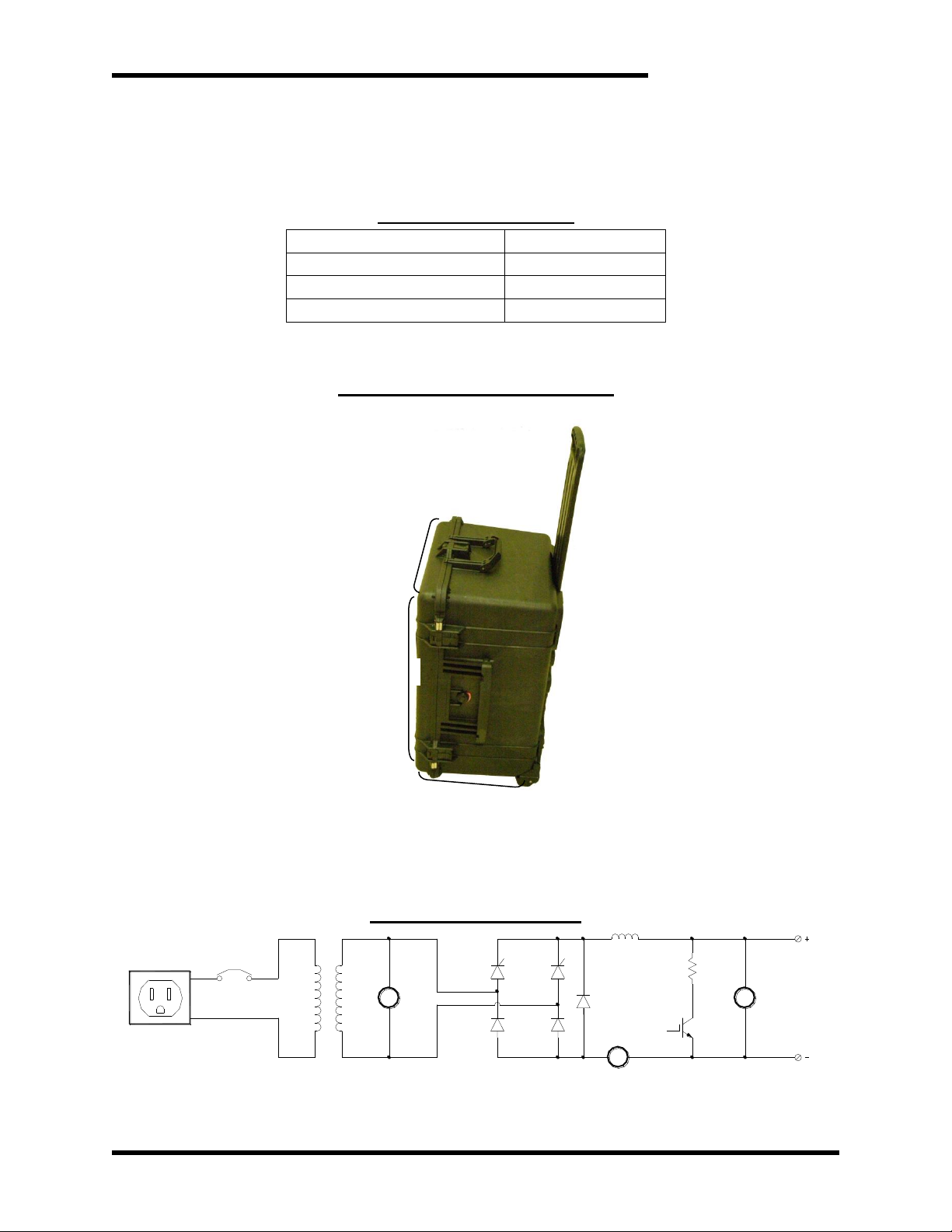
Figure 6-1:M3628PUT Dimensions
Note: Handle is not included in dimensions and retracts flush with the unit when not needed.
6.3. BLOCK DIAGRAM
Figure 6-2: Block Diagram
23
Page 24

M3628PUT
This page intentionally left blank
24
Page 25

User’s Manual
7. APPENDIX
7.1. APPLICATION NOTES
7.1.1. TYPICAL CAPACITOR BANK FORMING / TESTING PROCEDURE
Capacitors may undergo physical changes when stored for long periods.
Depending on the ambient conditions of the storage, this can be from six
months to two years. If the capacitors are rapidly taken to their rated
voltage, excessive leakage current may cause them to overheat and fail.
Capacitors also undergo physical and chemical changes after long periods
of use. If wear continues, these capacitors can fail, potentially causing
catastrophic damage. Capacitor lifetime is heavily dependent on use and
ambient conditions, and thus impossible to predict. Periodically measuring
the capacitance of a bank can help quantify the wear on and remaining
lifetime of the capacitors, helping avoid catastrophic failure without
periodically replacing the entire bank.
If the capacitor bank is part of a larger system, as a Variable Frequency
Drive, check with the drive manufacturer for specific instructions on how to
reform the capacitor bank.
A short description is below.
1. Ensure the capacitor bank is fully discharged and floated.
2. Apply power to the M3628PUT.
3. Attach the output leads to the capacitor bank directly. If you are
forming the capacitors in a drive, ensure that you are directly across
the DC bus, not attached through the braking circuit.
4. Select "Charging Profile" from the main menu.
5. Set the final voltage to the rated voltage of the capacitor bank.
6. Set the step voltage to approximately 10% of the rated voltage of the
capacitor.
7. Set the charging current to its maximum setting, unless counterindicated by the capacitor manufacturer.
8. Set the step hold time to at least 600 seconds.
9. Set the final hold time to at least 900 seconds, or consult the
equipment manufacturer for a suitable reforming time.
10. Begin charging the capacitor, listening for abnormal sounds or other
indications in the capacitors or attached equipment. Monitor the
current indicator to make sure there is not excessive leakage current,
and the voltage indicator to see that the voltage is rising. Continually
monitor the capacitor banks or attached equipment for abnormal signs,
such as noise, heating, or smell. Internal bleeder resistors on the
capacitor bank may require current during the process. Consult the
equipment manufacturer for more information.
IF AT ANY TIME ABNORMAL SIGNS ARE DETECTED, OR THE LOAD
CAPACITORS ARE OVERVOLTAGED, PRESS AND HOLD THE
IMMEDIATE DISCHARGE BUTTON TO END THE PROCEDURE.
11. After the final hold time, the unit will discharge the load and calculate
its capacitance. Wait until discharging is complete before dis-
25
Page 26

M3628PUT
connecting the load. Record the calculated capacitance and ESR
somewhere safe, along with the designation of the capacitor being
tested. Multiple tests may be performed if desired, to ensure
repeatability.
12. Once the procedure is completed successfully, the capacitor bank or
equipment can be returned to storage or put into use, as appropriate.
If the storage bank is put into storage, a ground strap should be placed
across the + and – of the ultracapacitor.
13. If the bank is put into service, test the capacitor bank periodically, on a
schedule recommended by the capacitor manufacturer. Ensure that all
tests are performed in a similar ambient temperature, otherwise
comparison between results may not be valid. If, over time, the bank
capacitance falls below the manufacturer-recommended percentage of
the original recorded capacitance, discard and replace the capacitor.
NOTES
26
Page 27

Page 28

D_M3528PUT_CMAN_VALL_01a 04/07/2014
521 Fairground Court ● Nashville, TN 37211 ● USA
 Loading...