

Page 1
IT
Libretto istruzioni per l'installazione e l'uso di cucine a gas, miste
ed elettriche. Serie:
GB
RU
GR
FR
NL
Instructions for use and maintenance of gas, gas-electric and
electric cookers. Series:
Rukovodstvo po ustanovke i `kspluatacii gazovyx, kombinirovannyx i `lektriheskix plit. Serii%
√‰ЛБ›В˜ БИ· ЩЛ ¯Ъ‹ЫЛ О·И ЩЛ Ы˘УЩ‹ЪЛЫЛ ОФ˘˙ИУТУ ˘БЪ·ВЪ›Ф˘,
ЛПВОЩЪИОТУ О·И МИОЩТУ. ªФУЩ¤П·:
Notice d'installation et d'utilisation des cuisinières à gaz et mixtes. Séries:
Handleiding voor installatie en gebruik van gas-, gemengde en
elektrische fornuizen. Serie:
66 N
Page 2

IT
Dati tecnici e caratteristiche ...................................................... 3
Installazione .......................................................................... 4 - 5
Aerazione del locale ................................................................ 4
Ubicazione .............................................................................. 4
Collegamento gas ................................................................... 4
Adattamento ai diversi gas ...................................................... 4
Sostituzione iniettori ................................................................ 4
Regolazione minimo ................................................................ 4
Allacciamento elettrico ............................................................ 5
Accensione elettrica ................................................................ 5
Dispositivo di sicurezza ........................................................... 5
Per l' utente ........................................................................ 6 - 11
Aerazione del locale ................................................................ 6
Accensione dei bruciatori ........................................................ 6
Accensione del forno a gas ..................................................... 6
Accensione del grill a gas ....................................................... 6
Dispositivo di sicurezza ........................................................... 6
Accensione elettrica ................................................................ 6
Uso piano di cottura a gas ..................................................... 6
Uso piastre elettriche .............................................................. 6
Uso forno a gas ...................................................................... 6
Uso grill a gas o elettrico ......................................................... 7
Uso forno elettrico multi 4........................................................ 7
Uso forno elettr.statico "4New" ................................................ 7
Uso forno elettr.ventilato "4" .................................................... 7
Uso forno elettrico multifunzione 6 .......................................... 7
Uso forno elettrico multifunzione ............................................. 7
Uso del girarrosto .................................................................... 8
Uso del contaminuti ................................................................. 8
Uso programmatore fine cottura monoco mando ..................... 8
Uso programmatore elettronico ............................................... 8
Per togliere la porta del forno .................................................. 9
Uso forno autopulente ............................................................. 9
Uso degli accessori del forno .................................................. 9
Uso piano cottura vetroceramica............................................. 9
Pulizia piano cottura vetroceramica ...................................... 10
Consigli e avvertenze ........................................................... 10
La Direttiva 2002/96/EC (RAEE) ........................................... 11
Regolamento Europeo 1935/2004 ........................................ 11
Figure ............................................................................... 59 - 61
Indice
Introduzione
- La nostra Società, nel ringraziarVi per aver scelto uno dei suoi
qualificati prodotti, desidera vivamente che otteniate da questa
apparecchiatura le migliori prestazioni, giustamente auspicate
al momento dell’acquisto. A questo scopo Vi invita a leggere
e seguire attentamente le istruzioni del presente libretto; considerando ovviamente solo quei paragrafi che riguardano accessori e strumentazione presenti nel Vostro apparecchio. La
Ditta costruttrice declina ogni responsabilità per danni a cose o
a persone derivanti da cattiva installazione o non corretto uso
dell’apparecchio stesso.
- Nello spirito di produrre apparecchi sempre più allineati alle tecniche moderne, e/o per una sempre migliore qualità del prodotto,
la nostra Società si riserva il diritto di apportare modifiche, anche
senza preavviso, senza per altro creare disagi in utenza.
- Per eventuali richieste di pezzi di ricambio, la domanda al Vostro
rivenditore deve essere completata dal n° di modello e n° di
matricola stampigliati sulla targhetta matricolare. La targhetta è
visibile aprendo il vano scaldapiatti (se esiste) oppure è situato
nello schienale della cucine.
- APPARECCHIO CONFORME ALLE DIRETTIVE:
- CEE 2009/142/CE (ex 90/396 )
- 2006/95/CE Bassa Tensione(sostituisce la 73/23/CEE e suc-
cessivi emendamenti)
- CEE 2004/108 (Radiodisturbi)
- Regolamento Europeo 1935/2004 (materiali a contatto con
alimenti )
- Regolamento Europeo 1275/2008 ( consumo energia in stand-by
e off-mode)
- CEE 40/2002
- CEE 92/75
- 2002/96/EC (RAEE)
- 2005/32/CE ( Energy-using Products)
PREMESSA
- Del presente libretto interessano solo voci e capitoli relativi agli
accessori presenti in cucina.
2
Page 3
Dimensioni esterne nominali Cucine 60x60
Altezza al piano di lavoro
Altezza a coperchio alzato
Profondità a porta chiusa
Profondità a porta aperta
Larghezza
Dimensioni utili Forno
Larghezza
Profondità
Altezza
Volume
BRUCIATORI A GAS (iniettori e portate)
Gas Bruciatore Iniettore portata
G20
ausiliario
20
semirap.
mbar
rapido
forno
grill
tripla corona ec.
G30
ausiliario
28-30
semirap.
mbar
rapido
G31
forno
37
grill
mbar
tripla corona ec.
G110
ausiliario
8
semirap.
mbar
rapido
forno
grill
tripla corona ec.
60x60 statico
cm. 45
cm. 47
cm. 34
l. 72
77
97
123
130
99
145
50
65
83
86
68
98
150
185
265
300
200
350
cm. 86,5
cm. 143
cm. 60
cm. 104
cm. 60
Forno
60x60 con ventola
cm. 41
cm. 38
cm. 31
l. 50
ridotta
(kW)
0,40
0,58
0,80
1,00
-
1,70
0,40
0,58
0,80
1,00
-
1,70
0,40
0,58
0,80
1,00
-
1,70
nominale
portata
(kW)
1,00
1,65
2,80
3,00
1,85
4,00
1,00
1,65
2,80
3,00
1,85
4,00
1,00
1,65
2,80
3,00
1,85
4,00
Cat.: vedi targhetta matricolare in copertina; Classe 1 oppure 2.1
Cucine di tipo "X"
PIASTRE ELETTRICHE
ø 145 1,2 kW - Piastra High-Light
ø 180 1,5 kW - Piastra Normale
1,8 kW - Piastra High-Light
2,0 kW - Piastra Rapida
ø 210 -120 2,1 - 0,7 kW - Piastra High-Light
ø 265 -170 2,2 - 1,4 kW - Piastra High-Light
Dati e caratteristiche tecnicheIT
EQUIPAGGIAMENTO
Tutti i modelli sono dotati di dispositivo di sicurezza per bruciatori
forno e grill.
Secondo i modelli, le cucine possono avere inoltre:
- Dispositivo di sicurezza per uno o più bruciatori del piano di cottura
- Accensione elettrica ai bruciatori superiori
- Accensione elettrica ai bruciatori forno e grill
- Pareti del forno a smalto autopulente
- Termostato (o rubinetto) per forno
- Illuminazione elettrica nel forno
- Girarrosto
- Bruciatore del grill
- Contaminuti meccanico
- Protezione pentole
- Una o più piastre elettriche
- Programmatore di fine cottura monocomando
- Programmatore elettronico
Per la DISPOSIZIONE DEI BRUCIATORI SUL PIANO, vedere i
modelli rappresentati in figura 1 in fondo al libretto.
Per lo SCHEMA ELETTRICO vedere la figura 2 in fondo al libretto.
La potenza elettrica è riportata sulla targhetta matricolare. La targhetta è visibile aprendo il vano scaldapiatti (se esiste) oppure è
situato nello schienale della cucina.
Una copia della targhetta è incollata sulla copertina del libretto (solo
per i prodotti a gas o misti).
Informazioni utili per il consumo energetico forni elettrici.
Queste informazioni completano ed arricchiscono quelle riportate
nella scheda tecnica ( stiker adesivo ) assieme al libretto istruzioni.
Forno 66
N statico
Marchio UE di qualità ecologica No No No
Tempo impiegato per cottura carico
normale statico in minuti
Tempo impiegato per cottura carico
normale ventilato in minuti
Consumo posizione stand-by in watt ... ... ...
Superficie utile del piano di cottura
leccarda in cm
2
1300 1143 1143
Fo r n o6 6
N venti-
43,2 ... 43,8
... 44,9 44,9
lato
Forno 66 N
mult ifunzi-
one
POTENZA FORNO ELETTRICO
platea cielo totale
forno statico 1,5 kW 0,7 kW 2,2 kW
forno multifunzione 1,5 kW 0,7 kW 2,2 kW
resistenza circolare forno 2,0 kW
grill 2,0 kW
3
Page 4

INSTALLAZIONE
L'installazione deve essere effettuata da persona qualificata che
dovrà attenersi alle norme di installazione vigenti.
Prima dell'installazione assicurarsi che le condizioni di distribuzione
locale (natura e pressione del gas) e la regolazione dell'apparecchio
siano compatibili.
Le condizioni di regolazione di questo apparecchio sono scritte
sulla targhetta in copertina.
Questo apparecchio non è raccordato ad un dispositivo di evacuazione dei prodotti di combustione. Dovrà essere installato e
raccordato conformemente alle regole di installazione in vigore.
Questo apparecchio può essere installato e funzionare solo in locali
permanentemente ventilati secondo le norme nazionali in vigore.
- Per l'Italia: UNI 7129 o 7131. Inoltre per gli apparecchi privi del
dispositivo di sicurezza per l’assenza di fiamma sul piano di lavoro
vale: "Questo apparecchio può essere utilizzato solo in ambienti
con ventilazione maggiorata secondo il D.M. 1 Aprile 1993".
AERAZIONE DEL LOCALE
I locali in cui sono installati gli apparecchi a gas devono essere
ben aerati al fine di permettere una combustione del gas e una
ventilazione corretta.
In particolare l'afflusso di aria necessaria per la combustione non
deve essere inferiore a 2 m3/h per ciascun kW di portata nominale
installato.
InstallazioneIT
- Il regolatore di pressione per GPL deve essere conforme a UNI
7432.
- Il raccordo della rampa è conforme a ISO 228-1.
- Evitare curve brusche nel tubo e tenerlo opportunamente scostato
da pareti calde.
ADATTAMENTO AI DIVERSI GAS
Qualora la cucina non fosse già predisposta per funzionare con
il tipo di gas disponibile, occorre trasformarla, procedendo nel
seguente ordine:
- Sostituzione degli iniettori (consultando il quadro a pag. 3);
- regolazione dell’aria primaria;
- regolazione dei "minimi".
Nota: Ad ogni cambiamento di gas incollare sull'etichetta matricolare l'indicazione del gas di nuova regolazione.
PER SOSTITUIRE GLI INIETTORI AI BRUCIATORI DEL PIANO
DI LAVORO (Fig. 4)
- Togliere la griglia, gli spartifiamma (A) e i bruciatori (B);
- svitare e togliere l'iniettore situato nel fondo di ciascun
portainiettore (C);
- sostituire l'iniettore conformemente alla tabella di pag. 3,utilizzando
una chiave da 7 mm, avvitare e stringere a fondo;
- verificare la tenuta del gas;
- riposizionare i bruciatori, gli spartifiamma e la griglia.
UBICAZIONE
Liberare la cucina dagli accessori d’imballaggio, comprese le pellicole che rivestono le parti cromate o inox.
Collocare la cucina in luogo asciutto, agevole, esente da correnti
d’aria. Tenere l’opportuna distanza da pareti che temono il calore
(legno, linoleum, carta, ecc.).
La cucina può essere installata libera (classe 1) oppure tra due
mobili (in classe 2 st 2-1) le cui pareti devono resistere a una
temperatura di 100°C e che non possono essere più alte del piano
di lavoro.
COLLEGAMENTO ALL’ALIMENTAZIONE DEL GAS
ATTENZIONE:
L'apparecchio viene predisposto con portagomma per installazione libera.
Nel caso di apparecchio installato tra due mobili classe 2 st.
2-1, l'unico collegamento ammesso è quello rappresentato in
fig. 3 - A (norma d'installazione UNI 7129 paragrafo 2.5.2.3).
Prima di collegare la cucina verificare che sia predisposta per il
gas con il quale sarà alimentata. In caso contrario eseguire la trasformazione indicata nel paragrafo "Adattamento ai diversi gas".
Il collegamento dell'apparecchio si fa a destra. Se il tubo deve
passare dietro, deve rimanere nella parte bassa della cucina. In
tale zona la temperatura è circa 50°C.
- Raccordo con tubo metallico flessibile o con tubo metallico rigido
(vedi Figura 3 disegno A):
Il raccordo si effettua con un tubo conforme alle norme nazionali,
avvitato direttamente sul raccordo, con l'interposizione di una
guarnizione di tenuta, fornita in dotazione.
- Raccordo con tubo in gomma su portagomma (vedi Figura 3
disegno B e C):
Si effettua con un tubo in gomma che porta il marchio di confor-
mità alla norma in vigore. Il tubo deve essere sostituito alla data
indicata e deve essere assicurato alle due estremità per mezzo di
fascette stringitubo normalizzate (UNI CIG 7141) e deve essere
assolutamente accessibile per il controllo del suo stato su
tutta la sua lunghezza.
- Dopo l'installazione verificare la buona tenuta dei raccordi.
- Per il funzionamento con B/P verificare che la pressione del gas
sia conforme a quanto indicato sulla targhetta matricolare.
IMPORTANTE:
- Impiegare solo tubi flessibili metallici (UNI CIG 9891) o in gomma
(UNI CIG 7140) normalizzati.
PER SOSTITUIRE L’INIETTORE AL BRUCIATORE DEL FORNO
(Fig. 5a)
- Allentare la vite di fissaggio del fondo forno;
- togliere il fondo forno (spingendolo all’indietro e sollevandolo);
- asportare il bruciatore forno dopo aver tolto la vite che lo fissa;
- sostituire l’iniettore utilizzando una chiave a tubo da 7 mm.
PER SOSTITUIRE L’INIETTORE AL BRUCIATORE DEL GRILL
(Fig. 5b)
- Asportare il bruciatore dopo aver tolto le due viti che lo fissano;
- sostituire l’iniettore utilizzando una chiave a tubo da 7 mm.
RACCOMANDAZIONI IMPORTANTI:
- Non serrare mai esageratamente gli iniettori;
- a sostituzione avvenuta, controllare la tenuta gas di tutti gli iniettori.
REGOLAZIONE DEL "MINIMO" BRUCIATORI PIANO Dl LAVORO
Nel caso che la cucina debba funzionare con gas liquido (B/P), il
by-pass dei rubinetti deve essere avvitato a fondo.
La cucina può essere dotata di rubinetti tipo "A", aventi il by-pass
all’interno (vi si accede introducendo un piccolo cacciavite nell’astina) o di tipo "B" aventi il by-pass all’esterno, sul lato destro (vi si
accede direttamente). Vedi figura 6.
Se la cucina deve funzionare con gas naturale si procede nel
seguente modo per entrambi i tipi di rubinetto:
- Accendere il bruciatore con la fiamma al max.;
- sfilare la manopola, per semplice trazione, senza fare leva sul
cruscotto, che si potrebbe danneggiare;
- accedere al by-pass con un piccolo cacciavite e svitarlo di 3 giri
circa (ruotando il cacciavite in senso antiorario);
- ruotare ulteriormente l’astina del rubinetto, in senso antiorario,
fino all’arresto: la fiamma si presenterà al max.;
- riavvitare molto lentamente il by-pass, senza spingere assialmente
il cacciavite, fino a creare una fiamma apparentemente ridotta di
3/4, curando tuttavia che sia sufficientemente stabile anche con
moderate correnti d’aria.
REGOLAZIONE DEL "MINIMO" BRUCIATORE FORNO
Nel caso che la cucina debba funzionare con gas liquido (B/P), il
by-pass del termostato deve essere avvitato a fondo.
Qualora invece la cucina debba funzionare con gas naturale si
procede nel seguente modo:
- Togliere il fondo del forno (spingendolo verso lo schienale ed
4
Page 5

InstallazioneIT
alzandolo);
- accendere il bruciatore del forno posizionando l’indice della manopola sulla posizione di "massimo";
- chiudere la porta del forno;
- accedere al by-pass del termostato o del rubinetto (vedi fig. 7);
- svitare il by-pass del termostato di circa 3 giri;
- trascorsi 5 o 6 minuti, portare l’indice della manopola sulla posizione di "minimo";
- riavvitare lentamente il by-pass osservando l’abbassarsi della
fiamma attraverso l’oblò della porta (chiusa) fino a che il dardo
della fiamma si presenta lungo 4 mm circa. Si raccomanda di
non tenere la fiamma eccessivamente bassa. Essa deve risultare
stabile anche con movimento deciso della porta del forno sia in
chiusura che in apertura;
- spegnere il bruciatore, rimontare il fondo forno.
ALLACCIAMENTO ALLA RETE ELETTRICA
Prima di procedere all’allacciamento, assicurarsi che:
- la tensione in rete corrisponda a quella indicata sulla targhetta
matricolare;
- la presa di "terra" sia efficiente.
Per il collegamento diretto alla rete, è necessario prevedere un dispositivo che assicuri la disconnissione dalla rete, con una distanza
di apertura dei contatti che consenta la disconnessione completa
nelle condizioni della categoria di sovratensione III, conformemente
alle regole di installazione.
Se l'apparecchio è equipaggiato di un cavo senza spina, la spina
da utilizzare è di tipo normalizzato e tenere conto che:
- cavo verde-giallo deve essere utilizzato per il collegamento a
terra;
- cavo blu per il neutro;
- cavo marrone per la fase;
- il cavo non deve entrare in contatto con pareti calde che siano
superiori a 75°C;
- in caso di sostituzione del cavo, deve essere di tipo H05RR-F o
H05V2V2-F con sezione adeguata (vedere schemi in fig. 2);
- in caso l'apparecchio sia fornito senza cavo, utilizzare cavo tipo
H05RR-F o H05V2V2-F con sezione adeguata (vedere schemi
in fig. 2).
IMPORTANTE: il costruttore declina ogni responsabilità per danni
dovuti all'assenza del rispetto delle regolamentazioni e delle norme
in vigore. Si raccomanda di controllare che il collegamento a terra
dell'apparecchio sia fatto in modo corretto (vedere schemi in fig.
2 in fondo al libretto).
- abbandonare la manopola in questa posizione ed accostare un
fiammifero acceso al bruciatore: NON DEVE ACCENDERSI.
Tempo occorrente per eccitare il magnete durante l’accensione:
10 secondi circa.
Tempo di intervento automatico, dopo lo spegnimento della fiamma
non oltre 90 secondi per i bruciatori del piano; non oltre 60 secondi
per i bruciatori forno e grill.
AVVERTENZE:
- Qualunque intervento tecnico all'interno della cucina deve essere
preceduto dal disinserimento della spina elettrica e dalla chiusura
del rubinetto del gas.
- Le verifiche di tenuta sul circuito gas non devono essere eseguite
con l'uso di fiamme. Se non si dispone di uno specifico dispositivo
di controllo, si può utilizzare schiuma od acqua abbondantemente
saponata.
- Richiudendo il piano di lavoro curare che i fili elettrici delle candele
(se vi sono) non si trovino in prossimità degli iniettori, per evitare
che vadano a posarsi sugli stessi.
PER CUCINE MUNITE Dl ACCENSIONE ELETTRICA
Le corrette distanze fra l’elettrodo ed il bruciatore sono indicate
nelle figure 5a,5b .
Se non scocca la scintilla è bene non insistere: si potrebbe danneggiare il generatore. Possibili cause di funzionamento anomalo
o inefficiente:
- candela umida, incrostata o rotta;
- distanza non corretta elettrodo-bruciatore;
- filo conduttore della candela rotto o privo di guaina;
- scintilla che scarica a massa (in altre parti della cucina);
- generatore o microinterruttore danneggiati;
- accumulo di aria nelle tubazioni (specie dopo lunga inattività della
cucina);
- miscela aria-gas non corretta (cattiva carburazione).
IL DISPOSITIVO Dl SICUREZZA
La corretta distanza fra l’estremità dell’elemento sensibile della
termocoppia ed il bruciatore é indicata nelle figure 5a,5b .
Per controllare l’efficienza della valvola, operare come segue:
- accendere il bruciatore e lasciarlo funzionare per 3 minuti circa;
- spegnere il bruciatore riportando la manopola sulla posizione di
chiusura (
- trascorsi 90 secondi per i bruciatori del piano, 60 secondi per i
bruciatori forno e grill, portare l’indice della manopola sulla posizione di “aperto”;
);
5
Page 6

IT
COME SI USA LA CUCINA
AERAZIONE DEL LOCALE
L'utilizzo di un apparecchio di cottura a gas porta alla produzione
di calore e umidità nel locale in cui è installato. Vigilare al fine di
assicurare una buona aerazione della cucina: mantenere aperti gli
orifizi di aerazione naturale, oppure installare una cappa di aspirazione forzata. Nel caso di un uso intensivo e prolungato può essere
necessaria un'aerazione supplementare per esempio, aprendo una
finestra, o un'aerazione più efficace, aumentando per esempio la
potenza della ventilazione forzata.
ACCENSIONE DEI BRUCIATORI DEL PIANO Dl LAVORO
- Premere e ruotare la manopola in senso antiorario fino al simbolo
segnato sul cruscotto (posizione di fiamma al max.);
- nel contempo accostare un fiammifero acceso alla testa del bru-
ciatore;
- volendo una riduzione della fiamma, ruotare ulteriormente la
manopola nello stesso senso portando l’indice della stessa sul
simbolo
PER BRUCIATORI DEL PIANO MUNITI DEL DISPOSITIVO Dl
SICUREZZA
- Premere e ruotare in senso antiorario fino al simbolo
scotto (posizione fiamma al max.);
- accostare un fiammifero acceso al bruciatore e mantenere la
manopola premuta a fondo per 10 secondi circa;
- abbandonare quindi la manopola ed accertarsi che il bruciatore
rimanga acceso. In caso contrario, ripetere l’operazione.
ACCENSIONE DEL BRUCIATORE FORNO
- Aprire la porta del forno;
- premere e ruotare la manopola in senso antiorario fino alla posi-
zione di "massimo";
- accostare un fiammifero acceso al foro centrale del fondo forno
e premere a fondo la manopola (vedi fig. 8);
- verificare l’avvenuta accensione attraverso i due fori laterali del
fondo mantenendo sempre premuta la manopola;
- dopo 10 secondi circa, abbandonare la manopola ed accertarsi
che il bruciatore sia rimasto acceso. In caso contrario, ripetere
l’operazione.
ACCENSIONE DEL BRUCIATORE GRILL (GRILL A GAS)
- Collocare la protezione manopole come indicato in fig. 11;
- premere e ruotare la manopola del forno verso destra, fino al-
l’arresto;
- accostare un fiammifero acceso al tubo forato del bruciatore e
premere a fondo la manopola (vedi fig. 9);
- verificare l’avvenuta accensione del bruciatore mantenendo
sempre premuta la manopola;
- dopo 10 secondi circa, abbandonare la manopola ed accertarsi
che il bruciatore sia rimasto acceso. In caso contrario, ripetere
l’operazione.
IL DISPOSITIVO Dl SICUREZZA
I bruciatori muniti di questo dispositivo hanno il pregio di essere
protetti in caso di spegnimento accidentale. Infatti, in tal caso,
l’erogazione del gas al bruciatore interessato viene autonomamente
bloccata, evitando in tal modo pericoli derivanti da una fuoriuscita
di gas incombusto: dallo spegnimento della fiamma, non devono
trascorrere più di 60 secondi per i bruciatori forno e grill o 90 secondi
per i bruciatori del piano di cottura.
PER CUCINE MUNITE DI ACCENSIONE ELETTRICA
Vale interamente quanto detto sopra, salvo che l’uso del fiammifero
è sostituito da una scintilla che si ottiene premendo, anche ripetutamente, il pulsante che si trova sul cruscotto, oppure premendo
la manopola del bruciatore che si intende accendere.Qualora
l'accensione elettrica si rilevasse difficoltosa per determinati tipi di
(posizione di fiamma al min.).
sul cru-
Per l'utente
gas, si consiglia di effettuare l'operazione con la manopola sulla
posizione di "minimo" (fiamma piccola).
- Per le cucine munite di accensione elettrica ai bruciatori forno
e grill, è imperativo accendere questi bruciatori con la porta del
forno totalmente aperta;
- Durante l'accensione dei bruciatori del forno e del grill che sono
provvisti del dispositivo di accensione, esso non deve essere
azionato per più di 10 secondi. Se dopo questi 10 secondi il bruciatore non è acceso, smettere di agire sul dispositivo, lasciando
la porta aperta e attendere almeno un minuto prima di riprovare
ad accendere il bruciatore. Qualora il malfunzionamento del dispositivo di accensione dovesse ripetersi, provvedere all'accensione
manuale e chiamare il servizio assistenza.
AVVERTENZE:
- Se, dopo una certa inattività della cucina, l’accensione risultasse
difficoltosa, è un fatto normale. Basteranno tuttavia pochi secondi
perché l’aria accumulatasi nelle tubazioni venga espulsa;
- in ogni caso, bisogna evitare una esagerata erogazione di gas
incombusto dai bruciatori. Se l’accensione non avviene in un
tempo relativamente breve, si ripete l’operazione dopo avere
riportato la manopola sulla posizione di chiusura ( );
- alla prima accensione del forno e del grill si potrà avvertire un
caratteristico odore e fumo uscire dalla bocca del forno stesso.
Ciò è dovuto al trattamento delle superfici ed a residui oleosi sui
bruciatori.
COME SI USANO I FUOCHI DEL PIANO DI COTTURA
Usare recipienti con diametro adeguato al tipo di bruciatore. Le
fiamme infatti non devono sporgere dal fondo delle pentole. Consigliamo:
- per bruciatore ausiliario = recipiente di almeno cm. 8 utilizzando
la griglia di riduzione fornita con la cucina
- per bruciatore semirapido = recipiente di almeno cm. 14
- per bruciatore rapido e tripla corona = recipiente di almeno cm.
22
NOTA: non stazionare mai la manopola in posizioni intermedie fra
il simbolo di fiamma al massimo
PER CUCINE MUNITE DI PIASTRE ELETTRICHE
Le diverse intensità di calore si ottengono nel seguente modo:
- posiz. 1 = intensità minima per tutte le piastre;
- posiz. 6 = intensità massima per piastre normali e piastre rapide
(con disco rosso);
- posiz. 0 = tutto spento
Le pentole non devono mai avere diametro inferiore a quello della
piastra ed il loro fondo deve essere piatto il più possibile (fig. 10).
AVVERTENZE:
- Non lasciare funzionare piastre non coperte da pentole, salvo la
prima volta, per circa 10 minuti, per far asciugare residui di olio
o di umidità;
- se la piastra deve rimanere a lungo inattiva, è bene ungerne
moderatamente la superficie verniciata;
- evitare le incrostazioni sulla piastra per non essere costretti all’uso
di abrasivi per pulirla.
COME SI USA IL FORNO A GAS
- Dopo aver acceso il bruciatore, lasciare riscaldare il forno per 10
minuti;
- predisporre la vivanda da cuocere in una teglia di normale commercio, e appoggiarla sulla griglia cromata;
- introdurre il tutto nel forno utilizzando di preferenza il gradino più
alto possibile e portare l’indice della manopola sulla posizione
desiderata;
- la fase di cottura può essere osservata attraverso l’oblò della
porta e con forno illuminato. In tal modo si eviterà di aprire frequentemente la porta stessa, salvo che per oleare o ungere la
vivanda;
NOTA: Per cucine prive di termostato:
- con la manopola in posizione di "massimo"
6
e la posizione di chiusura ( ).
= 280°C
Page 7
IT
- con la manopola in posizione di "minimo" = 150°C
- Tutte le altre temperature comprese fra 150°C ed 280°C si ricercano approssimativamente fra le posizioni di min. e max.
Non stazionate mai la manopola in posizioni intermedie fra i simboli
di "massimo"
COME SI USA IL GRILL A GAS
- collocare la protezione manopole (vedi fig. 11);
- accendere il bruciatore ed attendere qualche minuto per dare
tempo al bruciatore di riscaldarsi;
- posare la vivanda sulla griglia;
- introdurre il tutto sul gradino più alto del forno;
- collocare la leccarda sul gradino inferiore;
- richiudere dolcemente la porta appoggiandola alla protezione
manopole;
- dopo qualche minuto rivoltare la vivanda per esporre l’altro lato
ai raggi infrarossi; (il tempo di esposizione è subordinato al tipo
di vivanda ed al gusto personale dell’ utente).
Vedere tabella " Alimenti da grigliare"
Alimenti da grigliare Tempo in minuti
Carni basse o sottili
Carni moderatamente alte
Pesci sottili e senza squame
Pesci moderatamente voluminosi
Salsicce
Toast
Piccoli volatili
NOTA: al primo impiego del grill si nota una fuoriuscita di fumo dal
forno. Prima di mettere vivande a cuocere, occorre quindi attendere
che eventuali residui di olio sul bruciatore siano totalmente bruciati.
Il grill deve essere usato solo alla sua portata calorica nominale.
Durante l’uso l’apparecchio diventa molto caldo. Si dovrebbe fare
attenzione a non toccare gli elementi riscaldanti all’interno del
forno.
ATTENZIONE: le parti accessibili possono diventare molto calde
durante l’uso. I bambini dovrebbero essere tenuti a distanza.
COME SI USA IL GRILL ELETTRICO CON FORNO A GAS
- accendere resistenza grill;
- posare la vivanda sulla griglia;
- introdurre il tutto sul gradino più alto del forno;
- collocare la leccarda sul gradino inferiore;
- richiudere dolcemente la porta ;
- dopo qualche minuto rivoltare la vivanda per esporre l’altro lato
ai raggi infrarossi; (il tempo di esposizione è subordinato al tipo
di vivanda ed al gusto personale dell’ utente).
Vedere tabella "Alimenti da grigliare"
La resistenza del grill, collocata nella parte alta del forno, si mette
in funzionamento ruotando la manopola del termostato in senso
orario fino al simbolo del grill sul cruscotto.L’accensione della spia
rossa segnalerà l’avvenuto inserimento della resistenza.
FORNO ELETTRICO MULTI 4
Grazie ai diversi elementi riscaldanti comandati da un selettore e
regolati da un termostato, partendo dalla posizione 0 (spento) e girando la manopola in senso orario si hanno le seguenti posizioni:
- simbolo
accesa anche con l’indice della manopola su tutte le altre posizioni).
- simbolo :cottura convenzionale forno "statico", la temperatura
del forno viene regolata mediante la manopola del termostato.
- simbolo :cottura con forno ventilato, la temperatura del forno
viene regolata mediante la manopola del termostato.
- simbolo :accensione grill;
NOTA - La spia gialla si accende secondo l’intervento del termo-
e di chiusura ( ).
1° Lato 2° Lato
6
8
10
15
12
5
20
: accensione lampada forno (che rimarrà sempre
4
5
8
12
10
2
15
Per l'utente
stato.Prima di introdurre le vivande da cuocere, si lasci riscaldare
il forno per 10 minuti almeno.
FORNO ELETTRICO STATICO " 4 New"
Grazie ai diversi elementi riscaldanti comandati da un selettore e
regolati da un termostato, partendo dalla posizione 0 (spento) e girando la manopola in senso orario si hanno le seguenti posizioni:
- simbolo
cesa anche con l’indice della manopola su tutte le altre posizioni).
- simbolo
del forno viene regolata mediante la manopola del termostato.
- simbolo
del forno viene regolata mediante la manopola del termostato.
- simbolo
NOTA - La spia gialla si accende secondo l’intervento del termostato.Prima di introdurre le vivande da cuocere, si lasci riscaldare
il forno per 10 minuti almeno.
FORNO ELETTRICO VENTILATO "4 POSIZIONI"
Grazie ai diversi elementi riscaldanti comandati da un selettore e
regolati da un termostato, partendo dalla posizione 0 (spento) e girando la manopola in senso orario si hanno le seguenti posizioni:
- simbolo
accesa anche con l’indice della manopola su tutte le altre posizioni).
- simbolo :funzionamento della ventola.
- simbolo :cottura con forno ventilato, su uno o due livelli, la
temperatura del forno viene regolata mediante la manopola del
termostato.
- simbolo : accensione grill;
NOTA - La spia gialla si accende secondo l’intervento del termostato.Prima di introdurre le vivande da cuocere, si lasci riscaldare
il forno per 10 minuti almeno.
FORNO ELETTRICO MULTIFORNO " 6 POSIZIONI "
Grazie ai diversi elementi riscaldanti comandati da un selettore e
regolati da un termostato (da 50 a 250°C), partendo dalla posizione
0 (spento) e girando la manopola di selezione in senso orario si
hanno le seguenti posizioni:
- simbolo
- simbolo
mento della ventola.
- simbolo
del forno viene regolata mediante la manopola del termostato.
- simbolo
temperatura del forno viene regolata mediante la manopola del
termostato.
- simbolo
del termostato deve essere in posizione di temperatura massima.
- simbolo
forno viene regolata mediante la manopola del termostato.
In tutte le posizioni, tranne lo zero, si ha l’accensione della spia
rossa e della lampada forno.
NOTA: La spia gialla si accende secondo l’intervento del termostato.
Prima di introdurre le vivande da cuocere, si lasci riscaldare il forno
per 10 minuti almeno.
FORNO ELETTRICO MULTIFUNZIONE
Grazie ai diversi elementi riscaldanti comandati da un selettore e
regolati da un termostato, questo forno offre più modi di cucinare,
impostati su tre fonti di calore principali:
a) Propagazione forzata del calore (forno ventilato).
b) Propagazione spontanea del calore (convezione o forno stati-
co).
c) Raggi infrarossi (grill).
Partendo dalla posizione 0 (spento) e girando la manopola di selezione in senso orario si hanno le seguenti posizioni:
7
:accensione lampada forno (che rimarrà sempre ac-
:cottura lenta con resistenza platea , la temperatura
:cottura convenzionale forno "statico", la temperatura
:accensione grill;
:accensione lampada forno (che rimarrà sempre
:accensione lampada forno e spia rossa.
:accensione lampada forno e spia rossa, funziona-
:cottura convenzionale forno “statico”, la temperatura
:cottura con forno ventilato, su uno o due livelli, la
:accensione del grill (sul plafone forno), la manopola
:cottura veloce con forno ventilato, la temperatura del
Page 8
IT
- simbolo :accensione lampada forno e spia rossa, funzionamento della ventola.
- simbolo
ratura del forno viene regolata mediante la manopola del termostato.
- simbolo
temperatura del forno viene regolata mediante la manopola del
termostato.
- simbolo
temperatura del forno viene regolata mediante la manopola del
termostato.
- simbolo
del termostato deve essere in posizione di temperatura massima.
- simbolo
del termostato deve essere in posizione di temperatura massima.
Il girarrosto è in funzione.
- simbolo
plafone forno), la temperatura del forno viene regolata mediante
la manopola del termostato. Il girarrosto è in funzione.
In tutte le posizioni, tranne lo zero, si ha l’accensione della spia
rossa e della lampada forno.
NOTA: La spia gialla si accende secondo l’intervento del termostato.
Prima di introdurre le vivande da cuocere, si lasci riscaldare il forno
per 10 minuti almeno
COME SI USA IL GRILL ELETTRICO CON FORNO ELETTRICO
- per soli modelli con "Forno Elettrico " comandati da due
manopole separate (selettore - termostato) si deve grigliare
a porta chiusa, senza l'uso della protezione manopola.Con
la grigliatura a porta chiusa, non si devono utilizzare temperature superiori a 200°C.
COME SI USA IL GIRARROSTO
a) Con grigliatura a porta aperta.
- collocare la protezione manopole come indicato in figura 12;
- accendere il bruciatore del grill, oppure mettere in funzionamento
la resistenza del grill;
- infilzare la carne da cuocere nello schidione e fissarla al centro a
mezzo dei due forchettoni;
- infilare la punta dello schidione nel mozzo del motorino;
- privare lo schidione della sua impugnatura;
- collocare la leccarda sul gradino più basso del forno;
- richiudere dolcemente la porta appoggiandola alla protezione
manopole;
- avviare il motorino premendo l’apposito interruttore contrassegnato
con il simbolo del girarrosto.
- ungere la carne di tanto in tanto. A cottura avvenuta, avvitare
l’impugnatura sul mozzo dello schidione e sfilare il tutto dal mozzo
del motorino.
b) Con grigliatura a porta chiusa.
- come sopra, senza l'utilizzo della protezione manopola indicato
in fig. 12
ATTENZIONE: I forchettoni dello schidione potrebbero avere le
punte acuminate. Maneggiare con cautela.
COME USARE IL CONTAMINUTI (Fig.13)
Impostare il tempo che si ritiene necessario per la cottura ruotando
la manopola del contaminuti in senso orario. Al termine del tempo
impostato suonerà un allarme.
COME SI USA IL PROGRAMMATORE Dl FINE COTTURA
MONOCOMANDO (SENZA OROLOGIO) Fig.14
Consente di programmare la durata di cottura. Funzionamento:
- Posizionare la manopola sul tempo di cottura desiderato (120 minuti
al max. per il forno elettrico; 100 minuti al max. per il forno a gas).
- Scegliere la temperatura mediante la manopola del termostato e
:cottura convenzionale forno “statico”, la tempe-
:cottura con forno ventilato, su uno o due livelli, la
:cottura con forno ventilato, su uno o due livelli, la
:accensione del grill (sul plafone forno), la manopola
:accensione del grill (sul plafone forno), la manopola
:cottura con forno ventilato e accensione del grill (sul
Per l'utente
posizionare la manopola del selettore sul tipo di cottura prescelto.
- Quando la manopola del programmatore si posizionerà sul simbolo
0 la cottura sarà terminata. L’interruzione della cottura è automatica.
- Riportare la manopola del termostato sul simbolo
- Riportare la manopola del selettore sul simbolo 0.
N.B.: Il forno, senza l’uso della programmazione, funziona solamente
quando la manopola del programmatore è sulla posizione manuale .
COME SI USA IL PROGRAMMATORE ELETTRONICO (Fig. 15)
Consente di programmare l’ora di inizio e la durata di cottura in forno.
Se la cottura inoltre non necessita di controllo a vista, essa può avvenire
anche in assenza dell’utente.Al momento dell’installazione o dopo
un periodo di mancanza dell’alimentazione elettrica, il visualizzatore
lampeggia; è quindi necessario sincronizzare l’ora, altrimenti le
programmazioni non risultano corrette.
SlNCRONIZZAZlONE DELL’ORA
- Premendo contemporaneamente 2 tasti (DURATA COTTURA, FINE
COTTURA) ed il tasto "+" o "-" si imposta l’ora. Con tale operazione
vengono cancellati eventuali programmi precedentemente impostati
ed il simbolo AUTO lampeggia.
NOTA: quando il simbolo AUTO lampeggia non è possibile mettere
in funzione manualmente il forno.
TASTI "+" E "-"
- Azionando i tasti "+" o "-" il tempo aumenta o decresce ad una
velocità variabile a seconda della durata della pressione esercitata
sul tasto.
FUNZIONAMENTO MANUALE
- Azionare il tasto MANUALE: il simbolo AUTO si spegne (se
lampeggiante o acceso permanentemente), il simbolo PENTOLA
si illumina, ed è possibile mettere in funzione il forno agendo sulle
manopole del termostato forno e del selettore secondo le istruzioni
del manuale.
FUNZIONAMENTO AUTOMATICO CON DURATA E FlNE
COTTURA
- Facciamo un esempio: sono le ore 9.25; si desidera che il forno
entri in funzione alle ore 11.00 e che termini la cottura alle ore 12.00
(durata cottura 1 ora).
- Premere il tasto DURATA COTTURA ed entro 5 secondi premere
il tasto "+" fino all’indicazione 01.00, eventualmente aggiustare
l’indicazione col tasto "-". I simboli AUTO e PENTOLA si illuminano
in permanenza.
- Premere il tasto FINE COTTURA ed entro 5 secondi premere il tasto
"+" fino all’indicazione 12.00. Il simbolo PENTOLA si spegne, mentre
il simbolo AUTO rimane illuminato permanentemente.
- Posizionare la manopola del termostato forno sulla temperatura
desiderata, ed il selettore sul tipo di cottura prescelto; la spia rossa
si illumina, la luce del forno di accende ed il programmatore è
predisposto al funzionamento: alle ore 11.00 il forno viene acceso
automaticamente ed il simbolo PENTOLA si illumina.
- Al termine della cottura (ore 12.00) il simbolo AUTO lampeggia il
simbolo PENTOLA si spegne e un segnale acustico avverte della
fine cottura: per interromperlo è necessario premere un pulsante
qualsiasi.
- Posizionare quindi le manopole del termostato forno e del selettore
sulla posizione di spento.
FUNZlO N A M ENTO S E M IAUTOMATICO CON DURATA
COTTURA
- Facciamo un esempio: sono le 11.35 e si desidera che il forno
rimanga in funzione per 25 minuti a partire da questo momento.
- Premere il tasto DURATA COTTURA ed entro 5 secondi premere
il tasto "+" fino all’indicazione di 00.25, eventualmente aggiustare
l’indicazione con il tasto "-". I simboli AUTO e PENTOLA si illuminano
in permanenza.
- Posizionare la manopola del termostato forno sulla temperatura
desiderata, ed il selettore sul tipo di cottura prescelta; la spia rossa
si illumina, la luce del forno si accende ed il forno entra in funzione.
- Dopo 25 minuti il forno ed il simbolo PENTOLA si spengono, il simbolo
AUTO lampeggia ed il segnale acustico avverte della fine cottura:
per interromperlo è necessario premere un pulsante qualsiasi.
- Posizionare quindi le manopole del termostato forno e del selettore
8
.
Page 9
IT
sulla posizione di spento.
CONTAMINUTI
- Premere il tasto CONTAMINUTI e selezionare il tempo desiderato
mediante il tasto "+" o "-".
- Durante il funzionamento del contaminuti si illumina il simbolo
CAMPANA.
- Al termine del tempo impostato si mette in funzione il segnale
acustico e il simbolo CAMPANA si spegne.
SEGNALE ACUSTICO
- Il segnale acustico si mette in funzione al termine di una
programmazione ed ha la durata di 7 minuti.
- Per interromperlo prima si dovrà premere un tasto qualsiasi.
- Azionando il tasto "-" senza avere prima selezionato una funzione
è possibile cambiare la frequenza del segnale acustico. Si può
scegliere fino a 3 diversi tipi di segnale. Il segnale selezionato si
avvertirà fin-tantoché verrà tenuto premuto il tasto "-".
INIZIO PROGRAMMA E CONTROLLO
- Il programma ha inizio dopo ca. 4 secondi dall’impostazione.
- In qualsiasi momento è possibile controllare il programma impostato
premendo il tasto corrispondente.
ERRORI Dl PROGRAMMAZIONE
- Esempio: alle ore 12.15 si impostano 30 minuti di DURATA
COTTURA e si imposta il tempo di FINE COTTURA alle ore
12.30.
- L’errore di impostazione puo essere corretto variando la durata o il
tempo di fine cottura, oppure premendo il pulsante MANUALE e poi
si ripete correttamente la programmazione.
- In presenza di un errore di impostazione il forno non viene
inserito.
ANNULLAMENTO Dl UN PROGRAMMA
- Si può cancellare un programma premendo il tasto di DURATA
COTTURA e di seguito il tasto "-" fino a che sul display non compare
l’indicazione 0.00.
IMPORTANTE: ALLA FINE Dl OGNI COTTURA PROGRAMMATA
SI CONSIGLIA Dl PREMERE IL TASTO
NON FUNZIONA MANUALMENTE.
, ALTRIMENTI IL FORNO
Per l'utente
USO DEGLI ACCESSORI DEL FORNO
- La griglia del forno serve a supportare teglie di commercio per
contenere dolci, arrosti o direttamente le carni da cuocere al grill.
- La leccarda posizionata sotto la griglia serve per raccogliere i sughi
colati dagli alimenti cotti direttamente sulla griglia stessa. La leccarda può essere usata anche per cuocere gli alimenti.
- Se si effettua la cottura a forno ventilato, è possibile caricare contemporaneamente due griglie. Tuttavia, se gli alimenti differiscono
fra loro per quantità o qualità, anche i tempi saranno ovviamente
diversi.
USO DEL PIANO DI COTTURA IN VETROCERAMICA
La potenza delle piastre è dosata da un dispositivo sequenziale che
assicura un'eccellente regolazione della temperatura di cottura.
Le diverse intensità di calore sono graduate da 1 a 6. La manopola
può essere portata sulla posizione desiderata ruotandola verso
destra o verso sinistra.
Per le piastre a doppio circuito, la manopola si gira solamente in
senso orario, le diverse intensità di calore sono graduate da 1 a 6
per le sole zone centrali delle piastre.
Un ulteriore scatto in avanti, dopo l'ultima graduazione, accenderà
le restanti zone delle piastre.
Quando una delle piastre è calda, la spia E (vedere fig. 1) si accende
e non si spegnerà finché la temperatura di tutte le zone di cottura
non sarà scesa al di sotto dei 60° C circa.
Le quattro zone di cottura sono delimitate dai contorni serigrafati
sul piano. Per avere un buon rendimento e un consumo in energia
proporzionato, è indispensabile utilizzare esclusivamente pentole e
utensili il cui fondo sia spesso e perfettamente piano (vedi fig. 10).
Il diametro del fondo del recipiente deve essere almeno uguale ai
contorni segnati sul piano. Se il fondo del recipiente non copre la
zona riscaldante, si verifica uno spreco in energia.
È meglio se è leggermente più grande.
Il fondo dei recipienti e il piano di cottura devono essere puliti e
asciutti. L'inosservanza di questi consigli comporterebbe una perdita
di calore e quindi di energia.
PER TOGLIERE LA PORTA DEL FORNO
La porta può essere rimossa per poter pulire il forno in maniera
più agevole seguendo le seguenti istruzioni:
- aprire completamente la porta.
- posizionare due monete da 10 centesimi dentro le due fessure
delle cerniere.
- richiudere la porta fino ad avvertire la resistenza delle due
monete (fig.16).
- chiudere ulteriormente la porta e poi sollevarla tenendola per i lati
e portarla leggermente in avanti, é a questo punto che la porta
si estrae con facilità.
- per riposizionare la porta rimettere le cerniere nella loro posizione
assicurandosi che siano agganciate nelle loro sedi; abbassare
completamente la porta ed estrarre le monete precedentemente
inserite.
- richiudere la porta fino alla sua posizione di chiusura totale.
- controllare sempre lo stato di efficienza della guarnizione porta
forno, in caso di usura non esitare per la sostituzione presso il
servizio assistenza.
PER CUCINE CON FORNO AUTOPULENTE
Le due pareti laterali e quella frontale sono rivestite di smalto autopulente ad azione catalitica. Ogni 10 - 15 cotture si lascia funzionare,
con forno vuoto ed alla massima potenza.
Il tempo necessario per questa operazione è subordinato allo stato di
conservazione del forno stesso. Alcune proiezioni tendono ad indurirsi
e possono rendere il rivestimento inoperante. In effetti otturano i pori
dello smalto speciale e l’ossidazione non ha più luogo.
Bisogna allora, appena il forno è completamente raffreddato, rendere
la crosta più molle con acqua molto calda ed una spazzola tenera,
senza usare detergente, riaccendere poi il forno al massimo per
alcuni minuti.
(Importante: non usare mai abrasivi o spazzole metalliche).
Nota:
- Non cuocere mai direttamente sulle piastre.
- Con le piastre radianti, per guadagnare un po' di tempo, è possibile
iniziare la cottura a pieno regime alla posizione 6, poi riportare la
manopola alla posizione scelta per la preparazione.
- Tutte le piastre sono provviste di un limitatore di temperatura che
ne impedisce il surriscaldamento, anche in caso di funzionamento
di una piastra al massimo regime senza pentole o di utilizzo di
recipienti con fondo non piatto.
A titolo orientativo si può consultare il seguente quadro ricordandosi
tuttavia che si possono avere variazioni dovute alla qualità ed alla
quantità delle vivande messe a cuocere e al gusto di ciascuno.
Posizione
manopola
1 - 2 Tenuta in caldo, besciamella,creme
2 - 3 Riscaldamento cibi
3 - 4 Pasta, minestra di verdure, ragù
4 - 5 Ebollizione, arrosti
5 - 6 Verdure a vapore, bistecche, pesce
6 Grigliate, frittate, Costolette di agnello
ATTENZIONE
- Non fissare le piastre alogene durante il loro funzionamento, in
quanto la luce emessa dalle piastre potrebbe danneggiare gli
occhi.
- La superficie del vetroceramica è molto resistente, ma non infrangibile, e non deve essere utilizzato per depositarvi alcunchè
sopra.
9
Tipo cottura
Page 10

IT
- L'urto violento con oggetti appuntiti o molto duri può danneggiarla.
- Se si riscontrano rotture, incrinature o crepe sulla, superficie si
consiglia di sospenderne l'uso e di contattare subito il servizio
assistenza.
- Fogli in alluminio e recipienti in plastica non devono essere posti
su superfici calde.
- Durante il primo periodo di funzionamento il piano può emettere
un odore di bruciato, che scomparirà dopo alcune utilizzazioni.
IMPORTANTE:
I bambini, vista la loro statura, rischiano di non vedere la spia di
calore residuo. Occorre pertanto, fare attenzione che non appoggino
le mani sulle piastre, anche se le resistenze sono spente.
PULIZIA PIANO COTTURA IN VETROCERAMICA
La forma piatta del piano in vetroceramica facilita enormemente la
pulizia rispetto ai piani di cottura a piastre tradizionali. Lo sporco
leggero e non incrostato si toglie con un foglio di carta inumidito.
Per togliere lo sporco resistente si possono applicare gli stessi
metodi di pulizia solitamente adottati per i vetri e utilizzare quindi
prodotti specifici. In caso di fuoriuscita del contenuto della pentola
sul piano, togliere il deposito formatosi per mezzo di una spatola.
Se si rovesciano zucchero o sciroppo, bisogna provvedere a rimuoverli subito prima che si caramellizzino sul vetro. Allo stesso modo
occorre togliere immediatamente anche ogni residuo di pellicole
d'alluminio o di materie plastiche lasciato da oggetti inopportunamente appoggiati sulla zona di cottura ancora calda. L'alone
d'acqua e le tracce di calcare possono essere rimosse con aceto
di vino bianco. Ricordarsi sempre di sciacquare e asciugare la
superficie con carta assorbente dopo l'uso. Non utilizzare in alcun
caso detergenti abrasivi o corrosivi come bombolette spray per
forni, sgrassatori, prodotti togli-ruggine, detersivi lucidanti in polvere
e spugne abrasive. Evitare che si depositino granelli di sabbia durante la mondatura di verdure, per esempio, in quanto potrebbero
graffiare la superficie. Evitare di strisciare pentole a fondo ruvido
che potrebbero segnare il vetro o addirittura graffiarlo.
CONSIGLI ED AVVERTENZE DI ORDINE GENERALE
- Questo apparecchio non è destinato all’uso da parte di persone
(inclusi i bambini) con ridotte capacità psichiche o motorie, o con
mancanza di esperienza e conoscenza, a meno che ci sia una
supervisione o istruzione sull’uso dell’apparecchio da parte di una
persona responsabile per la loro sicurezza.
I bambini devono essere sorvegliati per assicurarsi che non giochino
con l’apparecchio.
- Qualsiasi intervento, all'interno del forno o ove vi sia la possibilità di
accedere a parti sotto tensione, deve essere preceduto sempre dal
disinnesco dell'alimentazione elettrica.
- Non utilizzare il vano scaldapiatti come ripostiglio per liquidi infiammabili od oggetti che temono il calore, come legno, carta, bombolette
a pressione, fiammiferi, ecc.
- Controllare frequentemente il tubo di raccordo in gomma curare che
sia sufficientemente lontano da pareti calde, che non abbia curve
brusche o strozzature, e che sia in buone condizioni. Il tubo deve
essere sostituito al più tardi alla data indicata e deve essere assicurato
alle due estremità per mezzo di fascette stringitubo normalizzate.
- Nel caso la rotazione dei rubinetti divenga difficoltosa nel tempo,
contattare il Servizio Assistenza Tecnica.
- Le parti smaltate o cromate si lavano con acqua tiepida saponata o
con detersivi non abrasivi. Per i bruciatori superiori e gli spartifiamma,
invece, si può usare anche uno spazzolino metallico per disincrostare.
Asciugare accuratamente.
- Non usare abrasivi per pulire parti smaltate o cromate.
- Lavando il piano di cottura, evitare inondazioni. Fare attenzione che
non entri acqua o altro nei fori di alloggiamento dei bruciatori; ciò
potrebbe risultare pericoloso.
- Le candele per l’accensione elettrica devono essere mantenute pulite
ed asciugate al termine di ogni impiego, soprattutto se vi sono stati
gocciolamenti o trabocchi dalle pentole.
- In caso di coperchio in vetro: Non chiuderlo finché i bruciatori
o le piastre del piano lavoro sono caldi perché potrebbe scheg-
Per l'utente
giarsi o rompersi.
- Non urtare le parti smaltate e le candele di accensione (se vi
sono).
- Quando la cucina non è in servizio, è buona norma chiudere il rubinetto centrale (o murale) del gas.
- Non usare per la pulizia materiali ruvidi abrasivi o raschietti metallici
affilati per pulire le porte di vetro del forno dato che possono graffiare
la superficie e causare la frantumazione del vetro.
- Non utilizzare pulitori a vapore per la pulizia dell’apparecchio.
- Non è previsto un piedistallo per l’installazione della cucina.
ATTENZIONE: L'uso di un apparecchio a gas per cucinare porta
alla produzione di calore, umidità e prodotti di combustione nella
stanza in cui è installato. Assicurarsi che la cucina sia ben ventilata specialmente quando l'apparecchio è in funzione: mantenere
i fori di ventilazione naturale aprire o installare un dispositivo di
ventilazione meccanica (cappa aspirante).
ATTENZIONE: Questo apparecchio è deve essere utilizzato solo
a scopo di cottura. Non deve essere utilizzato per altri scopi, ad
esempio per riscaldamento di ambienti.
L'utilizzo di apparecchi elettrodomestici comporta il rispetto di alcune
norme fondamentali, in particolare:
- Il piano di cottura in vetroceramica presenta una buona resistenza
meccanica e sopporta quindi minimi urti accidentali. Se in seguito
a un urto il piano presenta rotture o fessure, si consiglia di non
usare l'apparecchio, staccare l'allacciamento elettrico e contattare
il rivenditore.
- Non spostare mai la cucina tenendola per la maniglia porta
forno.
Consigli da seguire in caso di anomalie.
Prima di consultare il Servizio Assistenza di fiducia controllare
che:
- la spina sia correttamente inserita nella presa di corrente
- la spia generale di funzionamento sia accesa.
Se il problema persiste, consultare un tecnico qualificato e autorizzato che sia in grado di riparare il guasto.
Se la luce del forno non funziona, procedere come segue:
- staccare il collegamento all'alimentazione elettrica. Togliere il
vetro di protezione che si trova all'interno del forno nella parte
posteriore e sostituire la lampadina.
Si declina ogni responsabilità per danni a cose o a persone derivanti
da una cattiva installazione o da un uso non corretto della cucina.
In caso di anomalie, e soprattutto se si avvertissero fughe di gas
o di corrente, interpellare il tecnico senza alcun indugio.
10
Page 11
IT
LA DIRETTIVA 2002/96/EC (RAEE): INFORMAZIONI AGLI UTENTI
Fig. A
Questa nota informativa è rivolta esclusivamente ai possessori di
apparecchi che presentano il simbolo di (Fig. A) nell’etichetta adesiva riportante i dati tecnici, applicata sul prodotto stesso (etichetta
matricolare):
Questo simbolo indica che il prodotto è classificato ,secondo le norme
vigenti,come apparecchiatura elettrica od elettronica ed è conforme
alla Direttiva EU 2002/96/EC (RAEE) quindi, alla fine della propria
vita utile, dovrà obbligatoriamente essere trattato separatamente dai
rifiuti domestici, consegnandolo gratuitamente in un centro di raccolta
differenziata per apparecchiature elettriche ed elettroniche oppure
riconsegnandolo al rivenditore al momento dell’acquisto di una nuova
apparecchiatura equivalente.L’utente è responsabile del conferimento
dell’apparecchio a fine vita alle appropriate strutture di raccolta, pena
le sanzioni previste dalla vigente legislazione sui rifiuti.
L’adeguata raccolta differenziata per l’avvio successivo dell’apparecchio dismesso al riciclaggio, al trattamento e allo smaltimento ambientalmente compatibile contribuisce ad evitare possibili effetti negativi
sull’ambiente e sulla salute e favorisce il riciclo dei materiali di cui è
composto il prodotto.Per informazioni più dettagliate inerenti i sistemi
di raccolta disponibili, rivolgersi al servizio locale di smaltimento rifiuti,
o al negozio in cui è stato effettuato l’acquisto.
I produttori e gli importatori ottemperano alla loro responsabilità per il
riciclaggio, il trattamento e lo smaltimento ambientalmente compatibile sia direttamente sia partecipando ad un sistema collettivo.
Per l'utente
REGOLAMENTO EUROPEO N° 1935/2004 - MATERIALI A CONTATTO CON ALIMENTI.
INFORMAZIONE AGLI UTENTI.
Il simbolo rappresentato in figura, presente sulla confezione imballo, indica che i materiali che possono venire a contatto con gli
alimenti, in questo prodotto, sono conformi a quanto prescritto dal
regolamento europeo n° 1935/2004.
All’interno della cavità del forno gli alimenti potrebbero venire a
contatto con: griglie forno, leccarde, piastre pasticcere, vetro porta
forno, guarnizioni in gomma, schidioni girarrosti, pareti forno,
Sul piano di lavoro con: griglie, bruciatori e piano lavoro medesimo.
Nel cassetto scaldavivande con le pareti medesime.
11
Page 12

GB
Index
Technical data and specifications ....................... 13
Installation .....................................................14 - 15
Ventilation ..................................................................14
Positioning ...................................................................14
Gas connection............................................................14
Adapting to different types of gas ................................14
Replacing the injectors ................................................14
Minimum setting ..........................................................14
Electrical connection....................................................14
Electric ignition ............................................................15
Safety device ...............................................................15
For the user .................................................... 15- 20
Ventilation ....................................................................15
Igniting the burners ......................................................15
Igniting the gas oven ...................................................15
Igniting the gas grill......................................................15
Safety device ...............................................................15
Electrical switch-on ......................................................15
Using the gas hob........................................................16
Using the electric hot-plates ........................................16
Using the gas oven ......................................................16
Using the gas or electric grill .......................................16
Using the multi-function electric oven 4 .......................16
Using the static electric oven" 4 New " ........................16
Using the fan electric oven" 4 programs " ...................15
Using the multi-function electric oven 6 programs .......17
Using the multi-function electric oven ..........................17
Using the rotisserie ......................................................17
Using the minute minder..............................................17
Using the single-control cooking timer........................17
Using the electronic timer ............................................17
Removing the oven door .............................................18
Using the self-cleaning oven .......................................18
Using oven accessoires...............................................18
Using the ceramic hob .................................................18
Cleaning of the ceramic hob ........................................19
Advice and precautions ...............................................19
European Directive 2002/96/EC (WEEE) ....................20
European Regulation 1935/2004 .................................20
Figures ...........................................................59 - 61
Introduction
- Thank you for choosing one of our quality products, capable of
giving you the very best service. To make full use of its performance features, read the parts of this manual which refer to your
appliance carefully. The Manufacturer declines all responsibility
for injury or damage caused by poor installation or improper use
of the appliance.
- To ensure its appliances are always at the state of the art, and/or to
allow constant improvement in quality, the manufacturer reserves
the right to make modifications without notice, although without
creating difficulties for users.
- When ordering spare parts, inform your dealer of the model number and serial number punched on your appliance’s nameplate,
visible inside the warming compartment (if present) or on the back
of the cooker.
- APPLIANCE COMPLYING WITH THE FOLLOWING DIRECTIVES:
- EEC 2009/142/CE ( ex 90/396 )
- 2006/95/EC Low Voltage (replaces 73/23/EEC and subsquent
amendments)
- EEC 2004/108 (radio-frequency interference)
- European Regulation 1935/2004 (materials in contact with
food)
- European Regulation 1275/2008
- EEC 40/2002
- EEC 92/75
- 2002/96/EC (WEEE)
- 2005/32/CE ( Energy-using Products )
FOREWORD
- Refer only to the headings and sections covering accessories
actually installed on your cooker.
12
Page 13
Nominal external dimensions Cookers 60x60
Height at hob
Height with lid raised
Depth with door closed
Depth with door open
Width
Usable dimensions
Width
Depth
Height
Volume
60x60 static oven 60x60 fan oven
cm. 45
cm. 47
cm. 34
l. 72
cm. 86,5
cm. 143
cm. 60
cm. 104
cm. 60
cm. 41
cm. 38
cm. 31
l. 50
GAS BURNERS (injectors and flow-rates)
Gas Burner Injector low
G20
20
mbar
G30
28-30
mbar
G31
37
mbar
G110
8
mbar
auxiliary
semi-rapid
rapid
oven
grill
ultra-rapid ec.
auxiliary
semi-rapid
rapid
oven
grill
ultra-rapid ec.
auxiliary
semi-rapid
rapid
oven
grill
ultra-rapid ec.
77
97
123
130
99
145
50
65
83
86
68
98
150
185
265
300
200
350
flow-rate
(kW)
0,40
0,58
0,80
1,00
-
1,70
0,40
0,58
0,80
1,00
-
1,70
0,40
0,58
0,80
1,00
-
1,70
Cat.: seename plate on cover; Class 1 or 2.1
Type “X” cookers
ELECTRIC HOTPLATES
ø 145 1,2 kW - High-Light hotplate
ø 180 1,5 kW - Normal hotplate
1,8 kW - High-Light hotplate
2,0 kW - Rapid hotplate
ø 210 -120 2,1 - 0,7 kW - High-Light hotplate
ø 265 -170 2,2 - 1,4 kW - High-Light hotplate
nominal
flow-rate
(kW)
1,00
1,65
2,80
3,00
1,85
4,00
1,00
1,65
2,80
3,00
1,85
4,00
1,00
1,65
2,80
3,00
1,85
4,00
Technical data and specificationsGB
EQUIPMENT
All models are equipped with safety device for oven and grill burners.
Depending on the models, cooker may also have:
- Safety device for one or more hob burners
- Electric ignition on top burners
- Electric ignition on oven and grill burners
- Self-cleaning enamelled liners
- Oven thermostat (or tap)
- Electric oven lighting
- Rotisserie
- Grill burner
- Mechanical timer
- Pan retainers
- One or more electric plates
- Single-control end of cooking timer
- Electronic timer
For the LAYOUT OF HOB BURNERS see the models illustrated
in figure 1 at the back of this manual.
For the ELECTRIC WIRING DIAGRAM see figure 2 at the back
of this manual.
The electrical power is stated on the nameplate visible inside the
warming compartment (if present) or on the back of the cooker.
A copy of the nameplate is glued to the cover of this manual (for
gas or gas-electric products only).
Useful information concerning the energy consumption of
electric ovens.
This information completes and expands on the figures provided
on the technical data sticker supplied with the instruction manual.
Oven 66 N
static
EU environmental quality mark No No No
Time required to cook a normal load
in conventional mode in minutes.
Time required to cook a normal load
in fan mode in minutes.
Power consumption in stand-by
setting in Watts
Usable area of the dripping pan in
2
cm
43,2 ... 43,8
... 44,9 44.9
... ... ...
1300 1143 1143
Oven
66N fan
Oven 66 N
multifunctions
ELECTRIC OVEN POWER
bottom top total
static oven 1,5 kW 0,7 kW 2,2 kW
multi-function oven 1,5 kW 0,7 kW 2,2 kW
circular element 2,0 kW
grill 2,0 kW
13
Page 14

GB
INSTALLATION
The appliance must be installed by qualified staff working in accordance with the regulations in force.
Before installing, ensure that the appliance is correctly preset for
the local distribution conditions (gas type and pressure).
The presettings of this appliance are indicated on the nameplate
shown on the cover. This appliance is not connected to a flue gas
extractor device. It must be installed and connected in accordance
with the regulations in force.
This appliance may only be installed and may only operate in rooms
permanently ventilated in accordance with national regulations in
force.
VENTILATION
The rooms in which gas appliances are installed must be well ventilated in order to allow correct gas combustion and ventilation.
The air flow necessary for combustion is at least 2 m3/h for each
kW of rated power.
POSITIONING
Remove the packaging accessories, including the films covering the
chrome plated and stainless steel parts, from the cooker.
Position the cooker in a dry, convenient and draft free place. Keep
at an appropriate distance from walls which may be damaged by
heat (wood, linoleum, paper, etc.).
The cooker may be installed alone or between two kitchen units; in
this case, the sides of the units must withstand a temperature of 100
degrees C and they must not be higher than the cooker hob.
CONNECTING TO THE GAS SUPPLY
Before connecting the cooker, check that it is preset for the gas to be
used. Otherwise, make the conversion as described in the section
headed "Adapting to different gas types". The connection is on the
right; if the pipe has to pass behind the cooker, it must be kept low
down where the temperature is about 50 degrees C.
- Rigid connection (see Figure 3, diagram D):
The connection to the mains gas supply may be made using a
rigid metal pipe (D). Remove the hose connector and screw the
rigid union onto the threaded connection of the gas train. The
union for rigid connection is amongst the cooker accessories.
- Connection using a rubber hose (see Figure 3, diagrams B and
C):
Connect a rubber hose carrying the conformity mark currently in
force to the hose connector. The hose must be replaced at the
date indicated, and must be secured at both ends using standard
hose clamps. It must be absolutely accessible to allow its
condition to be checked along its entire length.
- Connection using a metal hose (see Figure 3, diagram D):
Make the connection using a hose which complies with national
standards, screwing it onto the connector with a ring seal, which
is delivered amongst the cooker accessories.
- After installation, check that all connections are airtight.
- For operation with butane/propane, check that the gas pressure
is as indicated on the nameplate.
IMPORTANT:
- Use only standard rubber hoses. For LPG, use a hose which
complies with the national regulations in force.
- Avoid sharp bends in the pipe and keep it well away from hot
surfaces.
References to the regulations covering the gas connection to the
appliance: ISO 7-1.
ADAPTING TO DIFFERENT TYPES OF GAS
If the cooker is not already preset to operate with the type of gas
available, it must be converted. Proceed as follows:
- Replace the injectors (see table on page 12);
- regulate the primary air flow;
- regulate the minimum settings.
N.B.: every time you change the type of gas, indicate the new type
of gas on the serial number label.
Installation
REPLACING THE HOB BURNER INJECTORS (Fig. 4)
- Remove the grid, the burner caps (A), and the burners (B);
- Unscrew and remove the injector in the bottom of each injector
holder (C);
- replace the injector in accordance with the table in page 12, using
a 7 mm socket wrench, tighten and screw right down;
- check that the system is gas-tight;
- replace the burners, the burner caps and the grid.
IMPORTANT:
- Never over-tighten the injectors;
- after replacing, check that all the injectors are airtight.
REPLACING THE OVEN BURNER INJECTOR (Fig. 5a)
- Loose the screw securing the oven bottom;
- remove the oven bottom (push back and raise);
- remove the oven burner, after taking out its fixing screw;
- replace the injector, using a 7 mm socket wrench.
REPLACING THE GRILL BURNER INJECTOR (Fig. 5b)
- Remove the burner after taking out the two screws which secure
it;
- replace the injector using a 7 mm socket wrench.
IMPORTANT:
- Never over tighten the injectors;
- after replacing, check that all the injectors are airtight.
SETTING HOB BURNER MINIMUM LEVELS
If the cooker is to work on bottled gas (butane/propane), the tap
by-pass must be screwed right down.
The cooker may be equipped with type A taps, with by-pass inside
(accessed by inserting a small screwdriver into the rod) or type B
taps, with by-pass on the outside on the right (accessed directly).
See figure 6.
If the cooker is to work on natural gas, proceed as follows for both
types of tap:
- Ignite the burner at maximum flame;
- pull off the knob, without using a lever against the control panel,
which might be damaged;
- access the by-pass with a small screwdriver and back off by about
3 turns (turning the screwdriver anti-clockwise);
- turn the tap rod anti-clockwise again until it stops: the burner will
be at maximum flame;
- screw the by-pass slowly back in, without pushing the screwdriver, until the flame has apparently shrunk to 1/4 of the maximum
size, checking that it is sufficiently stable even in quite strong
draughts.
SETTING OVEN BURNER MINIMUM LEVELS
If the cooker is to work on bottled gas (butane/propane), the thermostat by-pass must be screwed right down.
If the cooker is to work on natural gas, proceed as follows:
- Remove the oven bottom (push towards the back and raise);
- ignite the oven burner, turning the knob pointer to the maximum
setting;
- shut the oven door;
- access the thermostat or tap by-pass (see fig. 7);
- back off the thermostat by-pass by about 3 turns;
- after 5 or 6 minutes, turn the knob pointer to the minimum setting;
- slowly retighten the by-pass, watching the flame decrease in
size through the window in the closed oven door until the tongue
of the flame is about 4 mm long. Never keep the flame too low.
It must be stable even when the oven door is opened or closed
quickly;
- turn off the burner and replace the oven bottom.
CONNECTING TO THE ELECTRICAL MAINS
Before making the connection, check that:
- the mains voltage is as indicated on the nameplate;
- the earth connection is in good working order.
14
Page 15
GB
For direct connection to a power mains, a device that ensures
disconnection from the mains must be installed, with a opening
distance for the contacts that allows for a complete disconnection
under conditions of category III electrical overload, in conformity
with the installation instructions.
If the appliance power lead is not fitted with a plug, use an approved
standard type, remembering that:
- the green-yellow wire must be used for the earth connection;
- the blue wire is the neutral;
- the brown wire is live;
- the lead must never touch hot surfaces over about 75 degrees
C;
- replacement leads must be of type H05RR-F or H05V2V2-F of
suitable size (see diagrams in fig. 2).
- if the appliance is supplied without lead, using type H05RR-F or
H05V2V2-F cable of suitable size (see diagrams in fig. 2).
IMPORTANT:
The manufacturer declines all liability for damage due to failure to
comply with the regulations and standards in force. Check that the
appliance is correctly connected to the earth (see diagrams in fig.
2 at the back of the manual).
FOR COOKERS WITH ELECTRIC IGNITION
The correct gaps between the electrode and the burner are shown
in figures 5a,5b.
If no spark is generated, do not keep on trying as this might damage the generator.
Possible causes of malfunctions:
- spark plug damp, dirty or broken;
- electrode-burner gap not correct;
- spark plug wire broken or without sheathing;
- spark discharging to earth (to other parts of the cooker);
- generator or microswitch damaged;
- air has built up in the pipes (particularly if the cooker has been
out of use for a long time);
- air-gas mixture incorrect (poor fuel setting).
THE SAFETY DEVICE
The correct gap between the end of the thermocouple sensor and
the burner is shown in figures 5a,5b.
To check that the valve is working properly, proceed as follows:
- ignite the burner and leave it to work for about 3 minutes;
- turn off the burner by returning the knob to off position ( );
- after 90 seconds for hob burners, 60 seconds for oven and grill
burners, turn the knob pointer to the "on" position;
- release the knob in this position and move a burning match towards
the burner; IT MUST NOT IGNITE.
Time needed to excite the magnet during ignition: 10 seconds
approx.
Automatic tripping time, after flame has been turned off: not more
than 90 seconds for hob burners; not more than 60 seconds for
oven and grill burners.
IMPORTANT:
- Before doing any work inside the cooker, disconnect the mains
plug and shut the gas tap.
- Never use matches to check the gas circuit for leaks. If a specific
control device is not available, foam or very soapy water can be
used.
- When re-closing the hob, check that the electrical wires of the
spark plugs (if present) are not close to the injectors, so that they
cannot run across them.
Installation
For the user
HOW TO USE THE COOKER
VENTILATION
All gas cooking appliances produce heat and moisture in the rooms
where they are installed. Take care to ensure that the kitchen is
well ventilated; keep the ventilation openings unobstructed or install
an extractor hood with fan.In case of intensive or prolonged use,
additional ventilation may be required; open a window, or increase
the extractor fan power.
IGNITING THE HOB BURNERS
- Press the knob and turn it anti-clockwise until it reaches the
symbol on the control panel (maximum flame position);
- at the same time, move a burning match towards the burner
head;
- to reduce the flame, turn the knob further in the same direction until
its pointer is against the
FOR HOB BURNERS EQUIPPED WITH SAFETY DEVICE
- Press the knob and turn it anti-clockwise until it reaches the
symbol on the control panel (maximum flame position);
- move a burning match towards the burner, keeping the knob
pressed right down for about 10 seconds;
- then release the knob and check that the burner remains on.
Otherwise, repeat the operation.
IGNITING THE OVEN BURNER
- Open the oven door;
- press the knob and turn it anti-clockwise to the maximum flame
position;
- move a burning match towards the hole in the centre of the oven
bottom and press the knob right down (see fig. 8);
- look through the two holes in the sides of the bottom to check
that the burner has ignited, keeping the knob pressed down;
- after about 10 seconds, release the knob and check that the
burner remains on. Otherwise, repeat the operation.
IGNITING THE GRILL BURNER (GAS GRILL)
- Fit the control knob guard as shown in fig. 11;
- press the oven knob and turn it to the right until it reaches the
stop;
- move a burning match towards the perforated burner pipe and
press the knob right down (see fig. 9);
- check that the burner has ignited, keeping the knob pressed
down;
- after about 10 seconds, release the knob and check that the
burner remains on. Otherwise, repeat the operation.
SAFETY DEVICE
Burners equipped with this device have the advantage that they
are protected if they accidentally go out. If this occurs, the supply
of gas to the burner concerned is automatically cut off, preventing
the hazards deriving from a leak of unburnt gas. The gas supply
must be cut off within no more than 60 seconds for the oven and
grill burners or 90 seconds for the hob burners.
FOR COOKERS WITH ELECTRIC IGNITION
All the above applies, except that the match is no longer required; a
spark is obtained by pressing the button on the control panel once
or more, or by pressing the knob of the burner to be ignited.
If electronic ignition is difficult with some types of gas, set the knob
on the low (small flame) setting.
- For cookers with electric ignition of the oven and grill burners,
ensure the oven door is completely open when these burners are
ignited;
- Do not operate the ignition device for more than 10 seconds when
igniting the oven and grill burners. If the burner has not lit after
these 10 seconds, stop using the device, leave the door open
and wait one minute before trying again to ignite the burner. If the
15
symbol (minimum flame position).
Page 16
GB
ignition device malfunctions again, light the burner with a match
and call the after-sales service.
IMPORTANT:
- Difficulty in igniting burners is normal if the cooker has been out
of use for some time. The air accumulated in the pipes will be
expelled in a few seconds;
- Never allow too much unburnt gas to flow from the burners. If
ignition is not achieved within a relatively short time, repeat the
procedure after returning the knob to the off position ( );
- when the oven and grill are lit for the first time, a smell may be
noticed and smoke may come out of the oven. This is because of
the surface treatment and oily residues on the burners.
HOW TO USE THE HOB BURNERS
Use pans of diameter suitable for the burner type. The flames must
not project beyond the base of the pan. Recommended sizes:
- for auxiliary burners = pans of at least 8 cm using the adjusting
grid supplied with the cooker
- for semi-rapid burners = pans of at least 14 cm
- for rapid and triple flame burners = pan of at least 22 cm.
N.B.: Never keep the knob at settings between the maximum flame
symbol
FOR COOKERS EQUIPPED WITH ELECTRIC HOTPLATES
The different heat settings are obtained as follows:
- 1 = minimum setting for all hotplates;
- 6 = maximum setting for normal and rapid hotplates (with red
disc);
- 0 = off.
Pans must never be smaller in diameter than the hotplates and their
bottoms must be as flat as possible (see fig. 10).
IMPORTANT:
- Never leave hotplates on without pans, except when first used;
leave for about 10 minutes to dry oil or moisture residues;
- if the hotplate is to be out of use for a long time, apply a little grease
to its painted surface;
- do not allow spills to burn onto the hotplate, requiring the use of
abrasive cleaners.
HOW TO USE THE GAS OVEN
- After igniting the burner, leave the oven to heat up for about 10
minutes;
- place the food for cooking in an ordinary oven dish and place it
on the chrome-plated shelf;
- place in the oven on the highest possible runners, and turn the
knob pointer to the setting required;
- cooking can be observed through the window in the door with
the oven light on. This will avoid opening and closing the door
frequently, unless oil or fat has to be added to the dish.
N.B.: For cookers without thermostat:
- with the knob on the maximum setting
- with the knob on the minimum setting
- All other temperatures between 150 and 280 degrees C are
obtained approximately by positioning the knob between the
maximum and minimum settings.
Never leave the knob in positions between the maximum symbol
and the off setting ( ).
HOW TO USE THE GAS GRILL
- fit the knob guard (see fig. 11);
- light the burner and wait a few minutes to give the burner time to
warm up;
- place the foods on the chrome-plated shelf;
- insert on the highest runner;
- insert the drip tray on the bottom runner;
- gently close the oven door, resting it against the knob guard;
- after a few minutes, turn the food to expose the other side to the
infrared radiation (the cooking time depends on the type of food
and personal taste).
and the off position ( ).
= 280 degrees C
= 150 degrees C
For the user
The table below "Food to be grilled" will serve as a guide.
N.B.: the first time the grill is used smoke will come out of the oven.
Before inserting foods for cooking, wait until any oil residues on the
burner have completely burnt away.The grill must only be used at
its full rated heat.
The appliance becomes very hot during use. Care should be taken
not to touch the heating elements inside the oven.
ATTENTION: Accessible parts may be hot when the heating element is in use.Keep children well away.
Food to be grilled Time minutes
1st side 2nd side
Thin pieces of meat
Fairly thick pieces of meat
Thin fish or fish without scale
Fairly thick fish
Sausages
Toasted sandwiches
Small poultry
HOW TO USE THE ELECTRIC GRILL WITH GAS OVEN
- ignite the grill heating element;
- place the foods on the chrome-plated shelf;
- insert on the highest runner;
- insert the drip tray on the bottom runner;
- gently close the oven door;
- after a few minutes, turn the food to expose the other side to the
infrared radiation (the cooking time depends on the type of food
and personal taste). To see table " Food to be grilled"
The grill element in the top of the oven is switched on by turning the
thermostat knob clockwise to the grill symbol on the control panel.
The red light will come on to show the element is in operation.
MULTIFUNCTIONS ELECTRIC OVEN 4 POSITIONS
With different heating elements controlled using a selector switch
and regulated by a thermostat, starting from the 0 (off) position, the
knob can be turned clockwise to the following settings:
- symbol
pointer is turned to the other settings).
- symbol :conventional "static" oven cooking, the oven temperature is controlled using the thermostat knob.
- symbol :cooking with fan oven, on one or two levels, the oven
temperature is controlled using the thermostat knob.
- symbo l : grill on;
N.B. - The yellow light switches on and off as the thermostat is
tripped. Before placing food inside, allow the oven to heat up for
at least 10 minutes.
STATIC ELECTRIC OVEN " 4 New "
With different heating elements controlled using a selector switch
and regulated by a thermostat, starting from the 0 (off) position, the
knob can be turned clockwise to the following settings:
- symbol
pointer is turned to the other settings).
- symbol :slow cooking using the bottom element; the oven
temperature is regulated using the thermostat knob.
- symbol
perature is controlled using the thermostat knob.
- symbol :grill on.
N.B. - The yellow light switches on and off as the thermostat is
tripped.
Before placing food inside, allow the oven to heat up for at least
10 minutes.
ELECTRIC FAN OVEN WITH 4 COOKING PROGRAMS
With different heating elements controlled using a selector switch
and regulated by a thermostat, starting from the 0 (off) position, the
knob can be turned clockwise to the following settings:
16
: oven lamp on (it will remain on even if the knob
:oven lamp on (it will remain on even if the knob
:conventional "static" oven cooking, the oven tem-
6
8
10
15
12
5
20
4
5
8
12
10
2
15
Page 17
GB
- symbol : oven lamp on (it will remain on even if the knob
pointer is turned to the other settings).
- symbol
- symbol : cooking with fan oven, on one or two levels, the oven
temperature is controlled using the thermostat knob.
- symbol
N.B. - The yellow light switches on and off as the thermostat is
tripped. Before placing food inside, allow the oven to heat up for
at least 10 minutes.
MULTIFUNCTION ELECTRIC OVEN WITH 6 COOKING PROGRAMS
With different heating elements controlled using a selector switch
and regulated by a thermostat (from 50 to 250° C), starting from
the position 0 (off) the selector knob can be turned clockwise to
the following positions:
- symbol
- symbol
fan.
- symbol
perature is controlled using the thermostat knob.
- symbol
temperature is controlled using the thermostat knob.
- symbol
must be set at maximum temperature.
- symbol
ture is controlled using the thermostat knob.
In all positions except zero (0) the red warning light and the oven
light are on.
NOTE: The yellow warning light comes on according to thermostat
variations. Before putting food in to be cooked, the oven should be
pre-heated for at least 10 minutes.
MULTI-FUNCTION ELECTRIC OVEN
With different heating elements controlled using a selector switch
and regulated by a thermostat, this oven offers various cooking
methods. There are three principle sources of heat:
a) Forced heat diffusion (fan oven).
b) Spontaneous heat diffusion (static oven).
c) Infra-red rays (grill).
Starting from the 0 (off) position and turning the selector knob
clockwise, the following settings are obtained:
- symbol
- symbol
temperature is regulated by means of the thermostat knob.
- symbol
temperature is regulated by means of the thermostat knob.
- symbol
temperature is regulated by means of the thermostat knob.
- symbol
be on the maximum temperature setting.
- symbol
be on the maximum temperature setting. The roaster is in operation.
- symbol
oven temperature is regulated by means of the thermostat knob.
The roaster is in operation.
In all positions except zero (0) the red warning light and the oven
light are on.
NOTE: The yellow warning light comes on according to thermostat
variations. Before putting food in to be cooked, the oven should be
pre-heated for at least 10 minutes.
: operation of fan.
: grill on.
:oven light and red warning light on
: oven light and red warning light on, operation of
:conventional “static” oven cooking, the oven tem-
:cooking with fan oven,on one or two levels, the oven
:grill on (on oven top element), the thermostat knob
:quick cooking using the fan oven, the oven tempera-
:oven light and red light on, fan running.
:conventional oven cooking without fan, the oven
:fan oven cooking on one or two levels, the oven
:fan oven cooking on one or two levels, the oven
:grill (in top of oven) on, the thermostat knob must
:grill (in top of oven) on, the thermostat knob must
:fan oven cooking and grill (in top of oven) on, the
For the user
HOW TO USE THE ELECTRIC GRILL WITH ELECTRIC OVEN
- For models with “ Electric Oven” only,controlled by two knobs
separately (selector-thermostat), grilling is permitted with
the door closed, without using the front side. Temperatures
above 200°C. must not be used when grilling with the door
closed.
HOW TO USE THE ROTISSERIE
a) Grilling with the door open.
- fit the control knob guard as shown in figure 12.
- ignite the grill burner, or switch on the grill element;
- impale the meat for cooking on the spit and fix it in the centre of
the two forks;
- insert the end of the spit into the motor drive socket;
- remove the handle from the spit;
- place the drip tray on the bottom runner of the oven;
- gently close the oven door, resting it against the knob guard;
- start the rotisserie motor by pressing the switch on the symbol.
- baste the meat from time to time. When cooked, screw the handle
onto the spit and remove from the motor drive socket.
b) Grilling with the door closed.
- as above without using the knob protection as shown in fig.12
CAUTION: The spit forks may have sharp points. Handle with care.
HOW TO USE THE MINUTE MINDER (Fig. 13)
Set the cooking time considered necessary by turning the timer knob
clockwise. An alarm will sound at the end of the preset time.
USE OF SINGLE-CONTROL END OF COOKING TIMER (WITHOUT CLOCK) (Fig. 14)
This allows the cooking time to be programmed. Operation:
- Move the knob to the desired cooking time (120 mins max. for
the electric oven; 100 mins max. for the gas oven).
- Choose the temperature using the thermostat knob and move the
selector knob to the required cooking method.
- When the programming knob is at the 0 position the oven will
switch itself off. This is automatic.
- Move the thermostat knob back to symbol
- Move the selector knob to symbol 0.
N.B. If the timer is not used, the oven programming knob is to be
set to the manual position
USE OF THE ELECTRONIC TIMER (Fig. 15)
This allows the start time and cooking duration time to be programmed. If food does not need to be watched, this timer can be
selected even when the user is absent. Soon after installation and
at any electrical supply cut-outs the display flashes; the clock must
then be synchronized again to allow programming.
SETTING THE TIMER TO THE CURRENT TIME
- The current time is set by pressing the 2 buttons (COOKING TIME
and STOP) and the "+" or "-" button at the same time. Any previous
programmes are cancelled and the AUTO symbol flashes.
NOTE: when the AUTO symbol is flashing the oven cannot be used
manually.
"+" AND "-" BUTTONS
- Pressing the "+" or "- "buttons makes time go up or down at variable speed according to how long the button is pressed for.
MANUAL USE
- Press the MANUAL button: the AUTO symbol goes out (if flashing
or permanently on) the SAUCEPAN symbol lights up and the oven
can be used by adjusting the thermostat knob and the selector
switch according to the instructions given in the manual.
AUTOMATIC OPERATION WITH END OF COOKING AND DURATION TIMERS
- Let’s use an example: it is 9:25 am; you want the oven to switch
on at 11 am and switch off at 12 pm (cooking time 1 hour).
- Press the COOKING DURATION button and within 5 seconds press
"+" button until it shows 01.00, adjust using "-" button if necessary.
The AUTO and PAN symbols come on permanently.
17
.
.
Page 18

GB
- Press the END OF COOKING button and within 5 seconds press "+"
button until it shows 12.00. The PAN symbol goes out but the AUTO
symbol remains permanently on.
- Move the oven thermostat knob to the desired temperature, and
the selector switch to the required cooking method; the red warning light comes on the oven light comes on and the timer is ready
to start: at 11am the oven will come on automatically and the
symbol will light up.
- When cooking is over (12 am) the
symbol goes out and a buzzer sounds; to turn off the buzzer press
any button.
- Move the thermostat and selector knob to the OFF position.
SEMI-AUTOMATIC OPERATION WITH COOKING DURATION
SELECTION
- Let’s take an example: it is 11:35 am and you want the oven to
stay on for 25 minutes from now on.
- Press the
the "+" button until it shows 00.25, adjusting the time with the "-"
button if necessary. The
nently.
- Turn the oven thermostat knob to the desired temperature and the
selector switch to the required cooking method; the red warning
light comes on, the oven light comes on and the oven starts to
operate.
- After 25 minutes the oven and the PAN symbol go out. The AUTO
symbol flashes and the buzzer tells you that cooking is over: to
turn off the buzzer press any button.
- Then move the oven thermostat knob and the selector switch to
the OFF position.
MINUTE MINDER
- Press the
the "+" or "-" button.
- The BELL symbol lights up when the minute minder is in use.
- When the pre-set time is over, the buzzer sounds and the
symbol goes out.
BUZZER
- The buzzer sounds at the end of a programme and lasts for a
maximum of 7 minutes.
- To turn it off, press any button.
- Pressing the "-" button without having previously selected a
function the frequency of the signal changes. A selection from 3
possibilities can be made. The selected signal is audible as long
as the "-" button is pressed.
STARTING AND CHECKING A PROGRAMME
- The programme starts after about 4 seconds of it being set.
- The set programme can be checked at any point by pushing the
corresponding buttons.
PROGRAMMING ERRORS
- Example: at 12:15 pm a COOKING DURATION time of 30 minutes is
set and a
- The programme error can be rectified by changing the duration
or the end of cooking time, or by pressing the
programming again.
- If there is a programming error the oven will not come on.
ANNULLING A PROGRAMME
- A programme can be cancelled by pressing the
button and then the "-" button until the display shows 0.00.
IMPORTANT:
AT THE END OF EVERY PROGRAMMED COOKING OPERATION
YOU ARE ADVISED TO PRESS THE
THE OVEN CANNOT BE OPERATED MANUALLY.
REMOVING THE OVEN DOOR
The door can be removed for easier oven cleaning, proceeding
as follows:
- fully open the door.
- insert two small coins (e.g. 10 Eurocents) into the two slots in
the hinges.
- close the door until the coins start to prevent it closing further
COOKING DURATION button and within 5 seconds press
AUTO and PAN symbols light up perma-
MINUTE MINDER button and choose the desired time using
END OF COOKING is programmed in at 12:30 pm.
AUTO symbol flashes, the PAN
MANUAL button and
COOKING DURATION
BUTTON, OTHERWISE
PAN
BELL
For the user
(fig. 16).
- close the door some more and lift it off, holding it at the sides
and moving it slightly forward; this is the point at which the door
can be removed easily.
- to put the door back in place, return the hinges to their positions, checking that they have fitted into their seats.
- lower the door completely and remove the coins inserted earlier.
- fully close the door.
- always inspect the oven door gasket and if worn have it replaced at once by the after-sales service.
FOR COOKERS WITH SELF-CLEANING OVEN
The two side walls and the back are coated with a catalytic selfcleaning enamel.
Every 10-15 times it is used, leave the oven empty at full heat. The
time required for cleaning depends on the condition of the oven.
Some splashes tend to set hard and may clog the pores of the special coating, preventing oxidation and eliminating its self-cleaning
properties. In this case, as soon as the oven has completely cooled
apply very hot water to soften the deposits and use a soft brush,
without detergent, to remove them. Then switch the oven back on
at maximum heat for a few minutes.
(Important: never use metal brushes or abrasive substances).
HOW TO USE OVEN ACCESSORIES
- The oven shelf is designed to take normal oven dishes for cooking
sweets or roasts, or is used without a pan for cooking foods under
the grill.
- The drip pan under the grill is used to collect juices, which drip
from the food that is cooked directly on the grill. The drip pan can
also be used for cooking.
- Remember that cooking times may vary if food is cooked on two
shelves at the same time.
HOW TO USE THE CERAMIC HOB
The hotplate power has a sequential control device which ensures
excellent control of the cooking temperature.
The heat settings are from 1 to 6. The knob can be set in the required
position by turning it to right or left.
On dual circuit plates, the knob only turns clockwise and the heat
settings are from 1 to 6, for the central zones of the plates only.
If the knob is turned forward another notch after the last heat setting, the other zones of the plates will switch on.
When one of the cooking zones is hot, the warning light E (see fig. 1)
comes on; it will not go off until the temperature of all the hotplates
has dropped below about 60 degrees C).
The four cooking zones are indicated by the outlines screen-printed
on the hob. For good efficiency and appropriate energy consumption, only use saucepans and utensils with thick, perfectly flat bottoms (see fig.10). The diameter of the base of the pan must be at
least as large as the outline marked on the hob. If the bottom of
the pan does not cover the heating area, energy will be wasted.
Preferably, it should be slightly larger in diameter.
Pan bottoms and the cooking surface must be clean and dry. Otherwise heat, and thus energy, will be wasted.
Note:
- Never cook directly on the hotplates.
- To save time, cooking with the hotplates may be started at full
heat (knob on 6), turning down to the ideal temperature once the
contents of the pan have heated up.
- All the hotplates are equipped with a temperature limiter which
prevents them from overheating, even if a hotplate is operated at
the highest setting with no pan, or if pans with uneven bottoms
are used.
The table below will serve as a guide, bearing in mind that cooking times and temperatures may vary depending on the type and
amount of foods cooked and personal taste.
18
Page 19
GB
Knob
setting
1 - 2 Keeping foods warm, bechamel sauce, custard
2 - 3 Reheating foods
3 - 4 Pasta, vegetable soups, ragout
4 - 5 Boiling, roasting
5 - 6 Steamed vegetables, steaks, fish
6 Grilling, omelettes, lamb chops
CAUTION
- Do not look directly at the halogen hotplates while they are on,
as the light emitted from the hotplates may be harmful to your
eyes.
- The ceramic glass surface is very tough but it is not shatterproof
and it may not be used to place objects upon it.
- It may be damaged if struck violently by sharp or very hard objects.
- If breakages, crazing or cracks appear on its surface, stop using
it and contact the after-sales service immediately.
- Do not place aluminium foil or plastic film wrappings on the hob
while it is still hot.
- Soon after installation, the hob may give off a burnt smell; this will
disappear after the first few times it is used.
IMPORTANT:
Because of their height, children may fail to see the residual heat
warning light. Take care that they do not touch the hob, even if the
heating elements are switched off.
CLEANING OF THE CERAMIC HOB
The ceramic hob is much easier to clean than a hob with conventional hotplates. Light dirt can be removed with a sheet of damp
kitchen paper. To remove tougher dirt, use the same cleaning
methods as for glass, with specific detergents. If a pan boils over
onto the hob, use a spatula to remove the deposit formed. Sugar or
syrup must be removed immediately before it forms caramel on the
glass. Any residues of aluminium foil or plastic film wrappings accidentally placed on the hob while it is still hot must also be removed
at once. Water marks and traces of scale can be removed with white
wine vinegar. Always remember to rinse and dry the surface with
kitchen paper after use. Never use abrasive or corrosive detergents,
such as oven sprays, degreasers, rust-removers, powder polishing
detergents or abrasive sponges. Do not allow grains of sand to be
left on the hob when cleaning vegetables, for example, as they may
scratch the surface. Do not slide pans with rough bottoms over the
hob; they may mark or even scratch the glass.
GENERAL PRECAUTIONS
- This appliance must not be used by those with reduced mental or
motor capacities (including children), or by those who are not experienced or know how to work it, unless supervised or instructed
on its use by safety personnel.
Children must be supervised to ensure that they do not play with
the appliance.
- Always disconnect the power supply before any work inside the
oven or where live parts may be accessed.
- Never use the warming compartment for storing inflammable liquids or items which do not withstand heat, such as wood, paper,
aerosol cans, matches, etc.
- Make frequent checks on the rubber connection hose, ensuring
that it is well away from hot surfaces, that there are no sharp
bends or kinks, and that it is in good condition. The hose must be
replaced at the latest at the indicated date and must be secured
at both ends using a standard hose clamp.
- If taps become stiff to operate over time, contact the After-Sales
service.
- Wash enamelled or chrome-plated parts with soapy lukewarm
water or non-abrasive detergents. A metal brush may be used
Cooking process
For the user
to remove deposits from hob burners and flame caps. Dry thoroughly.
- Never use abrasives to clean enamelled or chrome-plated
parts.
- Do not use too much water when washing the hob. Take care that
no water or other substances enter the burner housing holes, as
this may be dangerous.
- The spark plugs for electric ignition must be kept clean and dry;
always check after use, particularly if there have been drips or
overflows from pans.
- Never move the cooker by means of the handle.
- Do not clean the glass doors of the oven with rough, abrasive
materials or sharp metal scrapers, since they may scratch the
surface and cause the glass to shatter.
- Do not use vapor jets to clean the appliance.
- The cooker does not have an installation stand.
- Never close glass lids until the hob burners or hotplates have
cooled completely; it might shatter or crack.
- Never knock enamelled parts or ignition spark plugs (where
present).
- The main or wall gas tap should be turned off when the cooker is
not in use.
CAUTION: The use of a gas cooking appliance results in the
production of heat, moisture and products of combustion in
the room in which it is installed. Ensure that the kitchen is well
ventilated especially when the appliance is in use: keep natural
ventilation holes open or install a mechanical ventilation device
(mechanical extractor hood).
CAUTION: This appliance is for cooking purposes only. It must
not be used for other purposes, for example room heating.
A number of fundamental precautions must be complied with when
using household electrical appliances. In particular:
- The ceramic-glass hob has good mechanical strength and thus
withstands small accidental knocks. If the knob is broken or
cracked by a knock, do not use the appliance, disconnect the
power supply and contact your dealer.
Advice in case of malfunctions
Before contacting your After-Sales Service, check that:
- the plug is fitted properly into the mains socket;
- the master pilot is on.
If the problem persists, consult a qualified, authorised technician
capable of repairing the fault.
If the oven light does not work, proceed as follows:
- Disconnect the power supply. Remove the protective glass on the
back of the oven and replace the bulb.
No liability is accepted for injury or damage caused by poor installation or improper use of the cooker.
In case of malfunctions, particularly gas leaks or short-circuits,
contact your engineer without delay.
19
Page 20
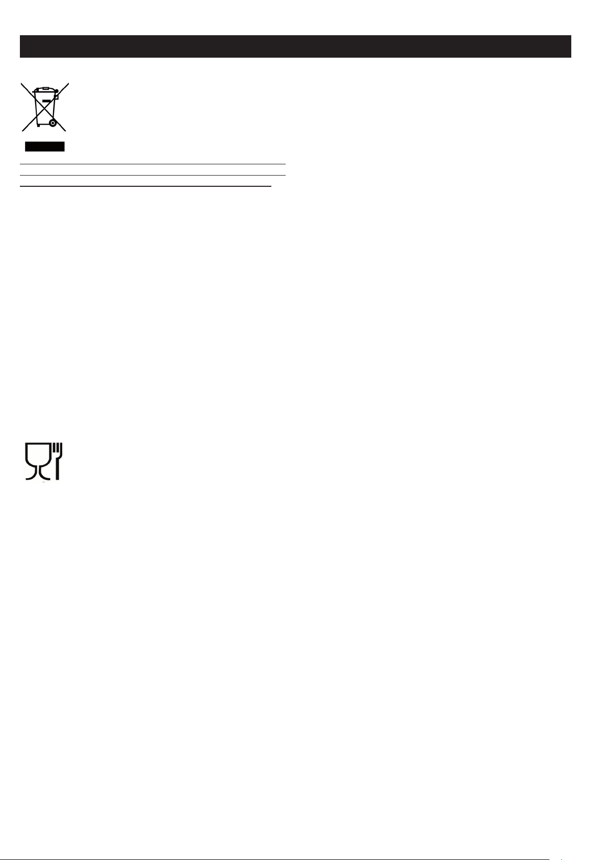
GB
EUROPEAN DIRECTIVE 2002/96/EC (WEEE): INFORMATION
FOR THE CONSUMER
Fig. A
This information is strictly addressed to those who have a product
showing the symbol below (Fig.A). This symbol is indicated on the
technical data sticker (rating label) placed on the product itself.
This symbol indicates that the appliance is considered as Waste
Electrical and Electronic Equipment and complies with the European
directive 2002/96/EC (WEEE).
Therefore this product is not to be treated as household waste. Instead it shall be handed over to the applicable collection point for the
recycling of electrical and electronic equipment or it can be handed
back to the retailer when you want to purchase a new equivalent
product.The consumer is responsible for a correct disposal of the
product towards an appropriate collection point. Otherwise the
consumer can be exposed to a penalty sanction by laws in force for
waste disposal. Appropriate separate waste collection followed by
recycling the product, the treatment and compatible environmental
disposal contributes to avoid negative effects towards the environment and health and helps to recycle material which the product is
composed of.For more detailed information regarding the available
waste collection systems of this product please contact your local
city office or contact the retailer where the product was purchased.
The manufacturers and importers will obey to their responsibility
for recycling, treatment and compatible environmental disposal by
participating directly and through a joint cooperative system.
For the user
EUROPEAN REGULATION NO 1935/2004 – MATERIALS IN
CONTACT WITH FOOD. NOTICE TO USERS.
The symbol shown here, which appears on the packaging, indicates
that the materials in this product which may come into contact with
food are compliant with the requirements of European Regulation
No 1935/2004.
Inside the oven chamber, food might come into contact with oven
shelves, dripping pans, pastry trays, oven door glazing, rubber
gaskets, rotisserie spits, and the sides of the oven itself.
On the hob, contact is possible with pan stands, burners and the
hob skin.
In the food-warmer, contact may occur with the sides of the compartment.
20
Page 21

RU
Soder'anie
Texniheskie dannye
ixarakteristiki .........................................................................21
Ustanovka ..............................................................................22 - 24
Ventilqciq pome]eniq ....................................................................... 22
Razme]enie .............................................................................................. 22
Podkl[henie k gazoraspredelitel;noj seti ............................... 22
Nastrojka na razlihnye tipy gaza .................................................. 23
Zamena 'iklerov ................................................................................... 23
Regulirovka minimal;nogo plameni .............................................. 23
Podkl[henie k `lektroseti ............................................................... 23
~lektriheskoe za'iganie ................................................................... 23
Predoxranitel;noe gazokontrol;noe ustrojstvo ...................... 24
Informaciq dlq potrebitelej ......................................24 - 29
Ventilqciq pome]eniq ....................................................................... 24
Za'iganie gorelok ............................................................................... 24
Vkl[henie gazovoj duxovki ............................................................... 24
Vkl[henie gazovogo grilq ................................................................. 24
Predoxranitel;noe ustrojstvo gazokontrolq ............................ 24
~lektriheskoe za'iganie ................................................................... 24
Ispol;zovanie gazovyx gorelok rabohej poverxnosti plity 25
Ispol;zovanie `lektriheskix konforok ....................................... 25
Ispol;zovanie gazovoj duxovki ....................................................... 25
Ispol;zovanie gazovogo ili `lektriheskogo grilq .................. 25
Ispol;zovanie konvekcionnoj `lektriheskoj duxovki ........... 25
`lektriheskoj duxovki " 4 New " ..................................................... 25
~LEKTRIHESKAQ DUXOVKA S SISTEMOJ VENTILQCII " 4 "..............25
Ispol;zovanie kombinirovannoj
Ispol;zovanie polifunkcional;noj
`lektriheskoj duxovki ....................................................................... 26
Ispol;zovanie vertela ....................................................................... 26
Duxovki s termoregulqtorom ........................................................... 26
Ispol;zovanie tajmera ....................................................................... 26
Ispol;zovanie programmiru[]ego
ustrojstva s cifrovymi hasami ..................................................... 27
Ispol;zovanie programmiru[]ego ustrojstva bez hasov ....... 27
Ispol;zovanie `lektronnogo
programmiru[]ego ustrojstva ........................................................ 28
Ispol;zovanie samoohi]a[]ejsq duxovki .................................. 28
Ispol;zovanie za]itnogo ogra'deniq
rabohej poverxnosti plity .............................................................. 28
алийгъбйЗДзаЦ лнЦдгйдЦкДеауЦлдйв ийЗЦкпзйлна иганх.. ................. .28
уалндД лнЦдгйдЦкДеауЦлдйв ийЗЦкпзйлна иганх..................................28
Rekomendacii po texnike bezopasnosti ........................................ 29
ЕВРОПЕЙСКИЙ РЕГЛАМЕНТ № 1935/2004 ............................................. 29
Директива 2002/96/EC (WEEE)...........................................................29
Risunki ..................................................................................59 - 61
СОfl УФВ‰ВОВМЛfl ‰‡Ъ˚ ‚˚ФЫТН‡ ФЛ·У‡ ФУ‚В¸ЪВ 9-БМ‡˜М˚И
ТВЛИМ˚И МУПВ, ЫН‡Б‡ММ˚И М‡ ТВВ·ЛТЪУИ ˝ЪЛНВЪНВ, М‡
ЫНУ‚У‰ТЪ‚В ФУ ˝НТФОЫ‡Ъ‡ˆЛЛ Л М‡ Т‡ПУП ФЛ·УВ:
AABBCDDDD
AA = ЙйС ЗхимлдД (М‡ФЛПВ: 99=1999, 00=2000, Л Ъ.‰.)
BB= зЦСЦгь ЗхимлдД (М‡ФЛПВ: 03 ЪВЪ¸fl МВ‰ВОfl „У‰‡ AA)
C= СЦзъ ЗхимлдД (М‡ФЛПВ: 1= ФУМВ‰ВО¸МЛН МВ‰ВОЛ BB,
2= ‚ЪУМЛН,
3=ТВ‰‡, 4=˜ВЪ‚В„, 5=ФflЪМЛˆ‡, 6=ТЫ··УЪ‡)
DDDD: ФУfl‰НУ‚˚И МУПВ ‚˚ФЫТН‡ (М‡ФЛПВ: 0004: ˜ВЪ‚ВЪ‡fl
ФОЛЪ‡, ‚˚ФЫ˘ВММ‡fl ‚ ‰ВМ¸ C МВ‰ВОЛ BB „У‰‡ AA).
Vstuplenie
nogo povyweniq kahestva nawix izdelij, fabrika ostavlqet
za soboj pravo vneseniq kakix-libo izmenenij da'e bez
predvaritel;nogo predupre'deniq, hto, odnako, ne vyzyvaet
problem ili zatrudnenij pri `kspluatacii.
- Esli vozniknet neobxodimost; zakaza zaphastej, nado sdelat;
zapros Vawemu prodavcu, gde sleduet ukazat; nomer modeli i nomer serii plity, ^prowtampovannye na fabrihnoj
opoznavatel;noj tablihke. ~ta tablihka mo'et byt; raspolo'ena vnutri otdeleniq razogreva tarelok (esli est;) ili
na zadnej storone plity.
- Plita sootvetstvuet normativam%
- CEE 2009/142/ ( ex - 90/396 )
- 2006/95/СЕ по низкому напряжению (заменяет 73/23/ЕЕС и последующие
поправки)
- CEE 2004/108 (po urovn[ radiopomex)
- ЕВРОПЕЙСКИЙ РЕГЛАМЕНТ № 1935/2004 (kontaktirovanie s pi]evymi produktami)
- ЕВРОПЕЙСКИЙ РЕГЛАМЕНТ № 1275/2008
- CEE 40/2002
- CEE 92/75
- 2002/96/EC (WEEE)
- 2005/32/CE ( Energy-using Producs )
POQSNENIE
- V nastoq]em rukovodstve predstavlq[t interes tol;ko te
paragrafy ili razdely, gde govorit;sq o priborax, kotorymi
osna]ena Vawa plita.
Nomin. naru'n. razmery Plity 60x60
Vysota do rabohej poverxnosti
Vysota s podnqtoj krywkoj
Glubina s zakrytoj dvercoj duxovki
Glubina s otkrytoj dvercoj duxovki
Wirina
Poleznye razmery Duxovka
Wirina
Glubina
Vysota
Ob=em
60x60 konvekc.
cm. 45
cm. 47
cm. 34
l. 72
Kat.% smotri fabrihnu[ tablihku na oblo'ke
Klass 1 ili 'e 2-1
Stepen; teplizolqcii ^X&
~LEKTRIHESKIE KONFORKI
ø 145 1,2 kVt - High-Light konforka
ø 180 1,5 kVt - Obyhnaq konforka
1,8 kVt High-Light konforka
2,0 kVt - Bystraq konforka
ø 210 -120 2,1 - 0,7 kVt - High-Light konforka
ø 265 -170 2,2 - 1,4 kVt - High-Light konforka
cm. 86,5
cm. 143
cm. 60
cm. 104
cm. 60
Duxovka
60x60 s vozduxod.
cm. 41
cm. 38
cm. 31
l. 50
- Nawa firma blagodarit Vas za vybor i pokupku odnogo iz nawix
vysokokahestvennyx izdelij. My gorqho nadeemsq, hto v Vawix
rukax nawi plity budut funkcionirovat; s maksimal;noj
otdahej i nailuhwimi rezul;tatami, opravdyvaq vse Vawi
o'idaniq. S `toj cel;[ predlagaem Vam vnimatel;no prohitat; nastoq]ee rukovodstvo i prider'ivat;sq tex ego ukazanij, gde reh; idet o priborax i sistemax, kotorymi osna]
ena Vawa plita. Fabrika - izgotovitel; snimaet s sebq vsqku[
otvetstvennost; za povre'deniq, neispravnosti i neshastnye
sluhai, vyzvannye nesobl[deniem rekomendacij po ustanovke
i `kspluatacii plity.
- Dlq togo, htoby vypuskat; plity v sootvetstvii s sovremennymi texnologiheskimi reweniqmi i#ili dlq postoqn-
MO}NOST: ~LEKTRIHESKOJ DUXOVKI 60x60
pod svod polnaq
Konvekcionnaq
duxovka 1,5 kVt 0,7 kVt 2,2 kVt
Kombinirovannaq
duxovka 1,5 kVt 0,7 kVt 2,2 kVt
Krugovaq spiral; duxovki 2,0 kVt
Gril; 2,0 kVt
21
Page 22

RU
Texniheskie dannye i xarakteristiki
GAZOVYE GORELKI ('iklery i mo]nosti)
Tip
Tip gorelki In'ektor Umen;wennaq
gaza
G20
20
mbar
G30
28-30
mbar
G31
37
mbar
G110
8
mbar
malaq
srednqq
bol;waq
duxovka
gril;
ÚÓÈ̇fl
malaq
srednqq
bol;waq
duxovka
gril;
ÚÓÈ̇fl
malaq
srednqq
bol;waq
duxovka
gril;
ÚÓÈ̇fl
77
97
123
130
99
145
50
65
83
86
68
98
150
185
265
300
200
350
mo]nost;
(kVt)
0,40
0,58
0,80
1,00
-
1,70
0,40
0,58
0,80
1,00
-
1,70
0,40
0,58
0,80
1,00
-
1,70
Nomin
mo]nost;
(kVt)
1,00
1,65
2,80
3,00
1,85
4,00
1,00
1,65
2,80
3,00
1,85
4,00
1,00
1,65
2,80
3,00
1,85
4,00
иУОВБМ˚В Т‚В‰ВМЛfl ‚ У·О‡ТЪЛ ˝МВ„УФУЪВ·ОВМЛfl ˝ОВНЪЛ˜ВТНЛı
‰ЫıУ‚УН.
щЪЛ Т‚В‰ВМЛfl Б‡‚В¯‡˛Ъ Л ‰УФУОМfl˛Ъ ЛМЩУП‡ˆЛ˛, ФЛ‚В‰ВММЫ˛
М‡ М‡НОВИНВ Т ЪВıМЛ˜ВТНЛПЛ ‰‡ММ˚ПЛ ‚ ЫНУ‚У‰ТЪ‚В ФУ
˝НТФОЫ‡Ъ‡ˆЛЛ
RASPOLO"ENIE GORELOK NA RABOHEJ POVERXNOSTI smotri modeli na risunke 1 v konce nastoq]ego rukovodstva.
SXEMU PODKL{HENIQ K ~LEKTROSETI smotri na risunke 2 v
konce nastoq]ego rukovodstva.
~lektriheskaq mo]nost; ukazana na fabrihnoj opoznavatel;noj
tablihki. ~ta tablihka mo'et byt; raspolo'ena vnutri otdeleniq razogreva tarelok (esli est;) ili na zadnej storone plity.
Odin `kzemplqr `toj tablihki nakleen na oblo'ke nastoq]ego
rukovodstva (tol;ko dlq gazovyx ili kombinirovannyx plit).
USTANOVKA
Ustanovku plity dol'en vypolnqt; kvalificirovannyj personal v strogom sootvetstvii s dejstvu[]imi polo'eniqmi
po texnike bezopasnosti.Pre'de hem pristupit; k ustanovke
ubedit;sq, hto parametry mestnoj gazoraspredelitel;noj
seti (priroda i davlenie gaza) podxodqt dlq funkcionirovaniq plity. Usloviq regulirovaniq dannoj plity ukazany na
`tiketke na oblo'ke. ~ta plita ne soedinena s ustrojstvom
otvoda produktov goreniq. Takoe ustrojstvo dol'no byt; ustanovleno i podkl[heno k plite v sootvetstvii s dejstvu[]imi
polo'eniqmi po ustanovke i `kspluatacii.
Ustanovka plit razrewaetsq tol;ko v postoqnno provetrivaemyx
pome]eniqx soglasno dejstvu[]im nacional;nym pravilam.
VENTILQCIQ POME}ENIQ
V pome]enii, gde predpolagaetsq ustanovka gazovyx plit,
dol'en byt; postoqnnyj pritok sve'ego vozduxa, hto obespehivaet gorenie gaza i pozvolqet xorowu[ ventilqci[. V hastnosti,
kolihestvo sve'ego vozduxa, neobxodimogo dlq goreniq gaza,
dol'no byt; ne men;we, hem 2 m
3
#has na ka'dyj kVt nominal;noj
ustanovlennoj mo]nosti.
å‡ÍËӂ͇ Öë˝ÍÓÎӄ˘ÂÒÍÓ„Ó
͇˜ÂÒÚ‚‡.
ЗВПfl ‚ ПЛМЫЪ‡ı, Б‡Ъ‡˜ВММУВ ‰Оfl
ТЪ‡ЪЛ˜ВТНУИ „УЪУ‚НЛ МУП‡О¸МУ„У
НУОЛ˜ВТЪ‚‡ ФУ‰ЫНЪУ‚.
ЗВПfl ‚ ПЛМЫЪ‡ı, Б‡Ъ‡˜ВММУВ ‰Оfl
‚ВМЪЛОЛЫВПУИ „УЪУ‚НЛ МУП‡О¸МУ„У
ÍÓ΢ÂÒÚ‚‡ ÔÓ‰ÛÍÚÓ‚.
иУЪВ·ОВМЛВ ‚ З‡ЪЪ‡ı ‚ ВКЛПВ
УКЛ‰‡МЛfl.
иУОВБМ‡fl ФОУ˘‡‰¸
ФУЪЛ‚Мfl ‚ ТП
2
~LEKTRIHESKAQ
STATIHESKAQ
DUXOVKA
66 N
No No No
43,2 ... 43,8
1300 1143 1143
~LEKTRIHESKAQ
DUXOVKA S
SISTEMOJ
VENTILQCIIt
66 N
... 44,9 44.9
... ... ...
~LEKTRIHESKAQ
DUXOVKA
S SISTEMOJ
VENTILQCII
66 N
KOMPLEKTACIQ
Plity vsex modelej ukomplektovany predoxranitel;nym
ustrojstvom dlq gorelok duxovki i grilq.Krome togo, v zavisimosti ot modeli, v komplektaci[ plity vxodit%
- Predoxranitel;noe ustrojstvo gazokontrolq dlq odnoj ili
neskol;kix gorelok rabohej poverxnosti plity
- ~lektriheskoe za'iganie gorelok rabohej poverxnosti
- ~lektriheskoe za'iganie gorelok duxovki i grilq
- Samoohi]a[]eesq `malirovannoe pokrytie stenok duxovki
- Termoregulqtor (ili kran) dlq duxovki
- ~lektriheskoe osve]enie duxovki
- Vertel
- Gorelka dlq grilq
- Mexaniheskij tajmer
- Za]itnoe ogra'denie rabohej poverxnosti
- Odna ili neskol;ko `lektriheskix konforok
- Programmiru[]ee ustojstvo duxovki s cifrovymi hasami
- Programmiru[]ee ustrojstvo bez hasov
- ~lektronnoe programmiru[]ee ustrojstvo
RAZME}ENIE
Vynut; plitu iz upakovki i snqt; s nee vse upakovohnye materialy, v tom hisle za]itnoe plenohnoe pokrytie xromirovannyx i stal;nyx ner'ave[]ix hastej. Ustanovit; plitu
v xorowo provetrivaemom suxom pome]enii bez skvoznqkov.
Plita ne dol'na soprikasat;sq s neustojhivymi k dejstvi[
temperatury materialami. Pri ee ustanovke sobl[dat; bezopasnoe rasstoqnie ot takix poverxnostej (kak derevo, linoleum,
bumaga i. t. d.). Mo'no ustanavlivat; plitu samu po sebe ili
me'du kuxonnoj mebel;[, pri uslovii, hto stenki `toj mebeli
vyder'iva[t temperaturu do 100°C i ix vysota ne prevywaet
vysotu rabohej poverxnosti plity.
PODKL{HENIE K GAZORASPREDELITEL:NOJ SETI
Pre'de hem podkl[hat; plitu k gazoraspredelitel;noj seti
ubedit;sq, hto tip gaza sovpadaet s tem, na kotoryj plita
nastroena. V protivnom sluhae dejstvujte soglasno opisani[
paragrafa ^Nastrojka na razlihnye tipy gaza&. Pri podkl[henii
plity gazovyj wlang dol'en proxodit; sprava. Esli wlang proxodit szadi, on dol'en raspolagat;sq v ni'nej hasti plity.
V `toj zone plita nagrevaetsq do 50°C.
- Soedinenie s gibkoj metalliheskoj truboj (ris. 3-A)
Soedinenie vypolnqetsq pri pomo]i truby, sootvetstvu[]ej
dejstvu[]im nacional;nym standartam. Truba navinhivaetsq na wtucer, na kotoryj predvaritel;no ustanavlivaetsq
uplotnitel;naq prokladka.
- Soedinenie s rezinovym wlangom (ris. 3-V i 3-S)
Soedinenie vypolnqetsq pri pomo]i rezinovogo wlanga, marka
katorogo sootvetstvuet dejstvu[]im nacional;nym standartam. Oba konca wlanga dol'ny byt; zakrepleny standartnymi
za'imami. V ustanovlennyj srok neobxodimo proizvodit;
zamenu wlanga i dostup k nemu dol'en byt; obleghen dlq
kontrolq ego sostoqniq po vsej dline.
- Posle podkl[heniq plity k gazoraspredelitel;noj seti
neobxodimo proverit; gazonepronicaemost; wtucerov i soedinenij.
- Dlq funkcionirovaniq plity na Butane#Propane neobxodimo
ubedit;sq, hto davlenie gaza seti sootvetstvuet davleni[,
ukazannomu na fabrihnoj opoznavatel;noj tablihke.
VNIMANIE%
22
Page 23

RU
- Ispol;zovat; tol;ko standartnye gibkie metalliheskie truby
ili rezinovye wlangi.
- Regulqtor davleniq dol'en sootvetstvovat; normativam.
- Soedinenie rampy sootvetstvuet normam ISO 228-1.
- Izbegat; sil;nyx izgibov i pere'atij truby ili wlanga i
starat;sq ne prislonqt; ego k razogretym stenkam plity.
NASTROJKA NA RAZLIHNYE TIPY GAZA
V sluhae, esli ispol;zuemyj dlq funkcionirovaniq plity gaz
otlihaetsq ot ukazannogo, neobxodimo nastroit; plitu, dejstvuq sledu[]im obrazom%
- Zamenit; 'iklery (v sootvetstvii s tablicej na ris 20).
- Vypolnit; regulirovku podahi vozduxa.
- Vypolnit; regulirovku minimal;nogo plameni vsex gorelok.
Primehanie% Pri ka'doj smene gaza nakleivat; na fabrihnu[
tablihku nazvanie novogo tipa gaza, na kotoryj nastroena
plita.
ZAMENA "IKLEROV GORELOK RABOHEJ POVERXNOSTI PLITY
(ris. 4)
- Snqt; rew\tku, rassekateli plameni (A) i gorelki (V)>
- otvintit; i snqt; 'ikler, raspolo'ennyj na dne ka'dogo
der'atelq 'iklera (S)>
- Zamenit; in'ektory v sootvetstvii s tablicej, prived\nnoj
na str. 20, zavintit; i zatqnut; ix do upora.
- Proverit; germetihnost; gaza.
- ustanovit; na pre'nee mesto gorelki, rassekateli plameni i
rew\tku.
VA"NYE REKOMENDACII
- Ni v koem sluhae ne zatqgivat; izliwne in'ektory.
- Proizvedq zamenu, prokontrolirovat; germetihnost; gaza. vsex
in'ektorov.
Z A M E N A " I K L E R O V G O R E L K I D U X O V K I
(ris. 5a)
- Otkrutite vint krepleniq dna duxovki.
- Snimite dno duxovki (sdvigaq ego nazad i podnimaq)
- Snimite gorelku duxovki, predvaritel;no otkrutiv krepq]ij
ee vint
- Zamenite 'ikler, ispol;zuq torcevoj trubhatyj kl[h na 7
mm.
ZAMENA "IKLEROV GORELKI GRILQ (ris. 5b)
- Snimite gorelku, predvaritel;no otkrutiv dva krepq]ie ee
vinta
- Zamenite 'ikler, ispol;zuq torcevoj trubhatyj kl[h na 7
mm.
REKOMENDACII
- Pri ustanovke 'iklerov nikogda izliwne ne zatqgivajte ix
kl[hom
- Posle zameny vsex 'iklerov prover;te ix gazonepronicaemost;.
REGULIROVKA MINIMAL:NOGO PLAMENI GORELOK RABOHEJ
POVERXNOSTI PLITY
V sluhae, esli plita funkcioniruet na s'i'ennom gaze (B#P),
regulirohnyj vint dol'en byt; zakruhen do upora. Plita mo'et
byt; osna]ena kranami tipa ^A&, s ustanovlennym vnutri regulirovohnym vintom ( regulirovat; kotoryj mo'no pri pomo]i
malen;koj otvertki herez ster'en;) ili tipa ^V& s naru'nym
regulirovohnym vintom s pravoj storony (ego mo'no regulirovat; neposredstvenno), smotri ris. 6.Esli dlq funkcionirovaniq plity ispol;zuetsq natural;nyj gaz, to nezavisimo ot
tipa krana dejstvovat; sledu[]im obrazom%
- Za'gite gorelku i ustanovite maksimal;noe plamq.
- Snimite ruhku regulqtora, potqnuv ee na sebq, ne na'imaq na
peredn[[ panel; plity vo izbe'anie ee povre'deniq.
- Pri pomo]i malen;koj otvertki otkrutite regulirovohnyj
vint priblizitel;no na tri oborota (vra]aq otvertku protiv
hasovoj strelki).
- Povernite e]e raz ster'en; krana protiv hasovoj strelki do
ego blokirovki. V `tom sluhae budet maksimal;noe plamq.
USTANOVKA
- Ohen; medlenno zakrutite regulirovohnyj vint, ne na'imaq
na otvertku, do tex por, poka plamq ne umen;witsq na 3#4. Pri
`tom obratite osoboe vnimanie na to, htoby plamq bylo dostatohno ustojhivym da'e pri umerennom potoke vozduxa.
REGULIROVKA MINIMAL:NOGO PLAMENI GORELKI DUXOVKI
V sluhae, esli plita funkcioniruet na s'i'ennom gaze (B#P),
regulirohnyj vint dol'en byt; zakruhen do upora. Esli dlq
funkcionirovaniq plity ispol;zuetsq natural;nyj gaz, to
nezavisimo ot tipa krana regulirovka minimal;nogo plameni
vypolnqetsq sledu[]im obrazom%
- Snimite dno duxovki (sdvigaq ego k zadnej stenke i podnimaq).
- Za'gite gorelku duxovki i ustanovite ukazatel; regulirovohnoj ruhki v polo'enie maksimal;nogo plameni.
- Zakrojte dvercu duxovki.
- Najdite regulirovohnyj vint termoregulqtora ili krana
(ris. 7)
- Otkrutite regulirovohnyj vint priblizitel;no na tri oborota.
- Herez 5-6 minut ustanovite ukazatel; ruhki v polo'enie
minimal;nogo plameni.
- M edle nno zakru tit e reg ulir ovoh nyj vint , nab l[da q
umen;wenie plameni herez steklo v dverce duxovki (dverca
zakryta) do tex por, poka konus plameni ne umen;witsq do
4 mm. priblizitel;no. Ne rekomenduetsq sliwkom umen;wat;
plamq. Ono dol'no byt; stabil;nym da'e pri bystrom
otkryvanii i zakryvanii dvercy duxovki.
- Vykl[hite gorelku i ustanovite dno duxovki na mesto.
PODKL{HENIE K ~LEKTROSETI
Pre'de hem podkl[hat; plitu k `lektroseti, neobxodimo
ubedit;sq, hto%
- naprq'enie vnewnej seti sootvetstvuet parametram, ukazannym na fabrihnoj opoznavatel;noj tablihke
- rozetka zazemleniq funkcioniruet
Для выполнения прямого подключения к сети необходимо
подготовить устройство, которое будет обеспечивать отключение от
сети, расстояние открытия контактов в котором должно позволять
полное отключение в условиях перенапряжение категории III и в
соответствии в правилами установки.
Esli plita ukomplektovana setevym wnurom bez vilki, to dlq
podkl[heniq mo'no ispol;zovat; standartnu[ vilku. Pri `tom
neobxodimo uhityvat; sledu[]ee%
- 'elto-zelenyj provod dol'en ispol;zovat;sq dlq zazemleniq
- goluboj provod dlq nejtrali
- korihnevyj provod dlq naprq'eniq seti
- w n u r ne do l 'en soprik a s a t ;sq so stenka m i pl i t y,
nagreva[]imisq bolee 75°C
- v sluhae zameny setevogo wnura ispol;zovat; wnur tipa
HO5RR-F ili HO5V2V2-F podxodq]ego seheniq (smotri
sxemy na ris. 2).
- esli plita postavlena bez setevogo wnura, pri podkl[henii
ispol;zovat; wnur tipa HO5RR-F ili HO5V2V2-F podxodq]ego
seheniq (smotri sxemy na ris. 2).
VNIMANIE%
Proizvoditel; ne neset otvetstvennosti za povre'deniq, vyzvannye nesobl[deniem vyweukazannyx trebovanij i dejstvu[]ix
pravil po texnike bezopasnosti pri podkl[henii plity.
Obqzatel;no prover;te, hto provod zazemleniq plity pravil;no
soedinen s set;[ zazemleniq (smotri sxemy na ris. 2).
PLITY, OSNA}ENNYE SISTEMOJ ~LEKTROZA"IGANIQ
Tohnye rasstoqniq me'du `lektrodom i gorelkoj ukazany na
ris. 5a,5b..
Esli iskra ne vybivaetsq, ne uporstvujte, t. k. mo'no povredit; generator. Sistema za'iganiq mo'et ne srabatyvat; po
sledu[]im prihinam%
- vla'naq, neispravnaq ili zagrqznennaq sveha.
- nepravil;no ustanovleno rasstoqnie me'du `lektrodom i
gorelkoj.
- tokoprovodqwij provodok svehi povre'den ili ogolen.
23
Page 24

RU
- iskrovoj razrqd uxodit v zeml[ (v drugix hastqx plity).
- povre'den generator ili mikrovykl[hatel;.
- s kopl eni e v ozdu xa v trub opr ovod ax (osob enn o p osle
dlitel;nogo perioda neispol;zovaniq plity).
- nepravil;no sostavlena gazovozduwnaq smes; (nepravil;noe
gorenie)
PREDOXRANITEL:NOE USTROJSTVO GAZOKONTROLQ
Pravil;noe rasstoqnie me'du koncami huvstvitel;nogo `lementa termopary i gorelkoj pokazano na ris. 5a,5b.
Dlq kontrolq funkcionirovaniq klapana gazokontrolq dejstvovat; sledu[]im obrazom%
- Za'gite gorelku i ostav;te ee vkl[hennoj priblizitel;no na
3 minuty.
- Vykl[hite gorelku i povernite ruhku regulqtora v polo'enie
^zakryto&, oboznahennoe simvolom (
- Herez 90 sekund v sluhae kontrolq gorelok rabohej poverxnosti i herez 60 sekund v sluhae gorelok duxovki i grilq
povernut; ruhku v polo'enie ^otkryto&.
- Ostav;te ruhku v `tom polo'enii i priblizit; za''ennu[
sspihku k gorelke% GORELKA NE DOL"NA ZA"EH:SQ.
Vo vremq za'iganiq trebu[tsq priblizitel;no 10 sekund dlq
vozbu'deniq magnita.
Klapan gaz okont rol q srabatyv aet avtoma tihes ki pos le
vykl[heniq plameni ne bolee hem herez 90 sekund dlq gorelok
rabohej poverxnosti plity i herez 60 sekund dlq gorelok
duxovki i grilq
PREDUPRE"DENIE
- Pered l[boj operaciej po histke ili texobslu'ivani[
otkl[hajte plitu ot `lektroseti i zakryvajte kran podahi
gaza.
- Pri podkl[henii plity k istohniku podahi gaza ne proverqjte germetihnost; stykov pri pomo]i plameni. Esli v
vawem rasporq'enii net special;nyx priborov dlq kontrolq
gazonepronicaemosti, mo'no ispol;zovat; penu ili koncentrirovannu[ myl;nu[ vodu.
- Ustanavlivaq na mesto rabohu[ poverxnost; plity ubedites;, hto `lektriheskie provodki svehej (esli ime[tsq) ne
soprikasa[tsq s 'iklerami i ne perekryva[t ix.
KAK ISPOL:ZOVAT: PLITU
VENTILQCIQ POME}ENIQ
~kspluataciq gazovoj plity soprovo'daetsq vydeleniem teploty i vla'nosti v pome]enii, gde ona ustanovlena. Po`tomu,
neobxodimo obespehit; ventilqci[ pome]eniq i podder'ivat;
otkrytymi estestvennye ventilqcionnye otverstiq ili ustanovit; vytq'noj zont.V sluhae dlitel;nogo i intensivnogo
ispol;zovaniq plity voznikaet neobxodimost; dopolnitel;noj
ventilqcii, kak, naprimer, otkryt; okno ili uvelihit;
mo]nost; vynu'dennoj ventilqcii i vytq'nogo zonta.
VKL{HENIE GORELOK RABOHEJ POVERXNOSTI PLITY
- Na'mite i povernite regulirovohnu[ ruhku protiv hasovoj
strelki i ustanovit; otmetku naprotiv simvola
nogo na perednej paneli plity (polo'enie maksimal;nogo
plameni).
- Zatem podnesite za''ennu[ spihku k gorelke.
- Dlq umen;weniq plameni povorahivajte ruhku v tom 'e napravlenii, ustanavlivaq otmetku naprotiv simvola
minimal;nogo plameni).
VKL{HENIE GORELOK RABOHEJ POVERXNOSTI, OSNA}ENNYX KLAPANOM GAZOKONTROLQ
- Na'mite i povernite regulirovohnu[ ruhku protiv hasovoj
strelki i ustanovite otmetku naprotiv simvola
nogo na perednej paneli plity (polo'enie maksimal;nogo
plameni).
- Zatem podnesite za''ennu[ spihku k gorelke i na'mite na ruhku do upora i der'ite ee pri'atoj v tehenii
priblizitel;no 10 sekund.
- Otpustite ruhku i ubedites;, hto gorelka za'glas;. V protivnom sluhae povtorite vse snahala.
USTANOVKA
).
, oboznahen-
(polo'enie
, oboznahen-
INFORMACIQ DLQ POTREBITELEJ
VKL{HENIE GORELKI DUXOVKI
- Otkrojte dvercu duxovki
- Na'mite na ruhku i povernite ee protiv hasovoj strelki do
polo'eniq maksimal;nogo plameni.
- Zatem podnesite za''ennu[ spihku k central;nomu otversti[
na dne duxovki i na'mite na ruhku do upora ( ris. 8).
- Ne otpuskaq ruhki ubedites; v tom, hto gorelka za'glas;,
nabl[daq plamq herez dva bokovyx otverstiq na dne duxovki
- Priblizitel;no herez 10 sekund otpustite ruhku i prover;te,
ne potuxla li gorelka. V protivnom sluhae povtorit; vse
snahala.
VKL{HENIE GORELKI GRILQ (GAZOVYJ GRIL:)
- Ustanovite planku dlq za]ity regulirovohnyx ruhek ot potoka gorqhego vozduxa, kak ukazano na ris. 11.
- Na'mite na regulirovohnu[ ruhku duxovki i povernite ee
vpravo do konca.
- Zatem podnesite za''ennu[ spihku k perforirovannoj trube
gorelki i na'mite na ruhku do upora (smotri ris. 9).
- Ne otpuskaq ruhku ubedites;, hto gorelka za'glas;.
- Priblizitel;no herez 10 sekund otpustite ruhku i ubedites;,
hto gorelka ne potuxla. V protivnom sluhae povtorite vse
snahala.
PREDOXRANITEL:NOE USTROJSTVO GAZOKONTROLQ
Preimu]estvo osna]ennyx `tim ustrojstvom gorelok sostoit v
tom, hto v sluhae neproizvol;nogo gaweniq pameni srabatyvaet
sistema za]ity. Dejstvitel;no, v `tom sluhae avtomatiheski
prekra]aetsq podaha gaza k potuxwej gorelke, pozvolqq takim
obrazom izbe'at; opasnosti utehki gaza. Posle neproizvol;nogo
gaweniq plameni klapan gazokontrolq srabatyvaet avtomatiheski ne bolee hem herez 90 sekund dlq gorelok rabohej poverxnosti plity i herez 60 sekund dlq gorelok duxovki i grilq.
PLITY, OSNA}ENNYE SISTEMOJ ZA"IGANIQ OT ~LEKTRIHESKOJ
ISKRY
Princip za'iganiq takoj 'e kak opisano vywe, za iskl[heniem
togo, hto vmesto spihki ispol;zuetsq iskra, poluhaemaq pri
na'atii, da'e mnogokratnom, raspolo'ennoj na perednej
paneli knopki, ili 'e na'imaq na rukoqtku gorelki, kotoraq
dol'na byt; vkl[hena. V sluhae, esli gorelka ne za'igaetsq,
poprobovat; e]e raz, ustanoviv regulirovohnu[ ruhku v po-
lo'enie minimal;nogo plameni (
- Esli plita osna]ena sistemoj `lektroza'iganiq gorelok duxovki i grilq, pri ix vkl[henii obqzatel;no der'at; dvercu
duxovki polnost;[ otkrytoj.
- Vo vremq vkl[heniq gorelok duxovki i grilq, osna]ennyx
sistemoj `lektroza'iganiq, ne na'imjte na knopku za'iganiq
bolee hem na 10 sekund. Esli herez 10 sekund gorelka ne za'getsq, otpustite knopku, otkrojte dvercu duxovki i podo'dite po
krajnej mere minutu pre'de hem povtorit; vkl[henie. Esli
'e gorelka ne vkl[haetsq po prihine neispravnosti sistemy
`lektroza'iganiq, to za'gite gorelku vruhnu[ pri pomo]i
spihki, a zatem vyzovite specialista po texobslu'ivani[.
PREDUPRE"DENIE
- Obyhno posle dlitel;nogo neispol;zovaniq plity srazu
ne udaetsq za'eh; gorelki. Pered za'iganiem dostatohno
podo'dat; neskol;ko sekund, poka ne vyjdet skopivwijsq v
truboprovodax vozdux.
- Starajtes;, htoby vmeste s vypuskaemym iz gorelok vozduxom ne vywlo mnogo gaza. Esli gorelka ne za'getsq v tehenii
neskol;kix sekund, povtorite za'iganie, predvaritel;no
povernuv regulirovohnu[ ruhku v polo'enie zakryvaniq (
), a zatem vnov; otkryv ee.
- Kogda duxovka ili gril; ispol;zu[tsq vpervye, iz otverstiq
duxovki mo'et poqvit;sq dym i nepriqtnyj zapax, vyzvannyj
razogrevaniem `malirovannogo pokrytiq stenok duxovki i
ostatkov maslqnistoj smazki gorelok.
ISPOL:ZOVANIE KONFOROK GAZOVOJ PLITY
Ispol;zujte kastr[li s diametrom dna, podxodq]ego k dannomu razmeru konforki. Plamq ne dol'no vyryvat;sq iz pod
24
).
Page 25

RU
kastr[li. Rekomenduetsq%
- dlq maloj gorelki ispol;zovat; kastr[li diametrom 8
sm, ustanavlivaq postavlqemu[ vmeste s plitoj setku dlq
umen;weniq diametra gorelki.
- dlq srednej gorelki ispol;zovat; kastr[li diametrom 14
- dlq bystroj gorelki ili tÓÈ̇fl gorelki / \mkost; s diametrom
ne menee 22 sm.
нУИМ‡fl „УВОН‡ ФЛ„У‰М‡ ‰Оfl ЛТФУО¸БУ‚‡МЛfl Н‡ТЪ˛О¸ Wok.
PRIMEHANIE% ni v koem sluhae ne ostavlqt; ruhku v prome'utohnyx polo'eniqx me'du simvolom maksimal;nogo
plameni
. i polo'eniem "zakryto" ( ).
INFORMACIQ DLQ POTREBITELEJ
Prigotovlqemoe na grile bl[do Vremq v minutax
1 storona 2 storona
Tonkie kuski mqsa
Dostatohno tolstye kuski mqsa
Melkaq ryba bez hewui
Dostatohno krupnaq ryba
Sosiski
Tosty
Melkaq ptica
6
8
10
15
12
5
20
4
5
8
12
10
2
15
PLITY S ~LEKTRIHESKIMI KONFORKAMI
Konforki ime[t razlihnu[ intensivnost; nagrevaniq v zavisimosti ot polo'eniq regulqtora.
- polo'enie 1 / minimal;noe nagrevanie vsex konforok
- polo'enie 6 / maksimal;noe nagrevanie obyhnyx i bystryx
konforok (s krasnym diskom)
- polo'enie 0 / vykl[henie vsex konforok.
Ne ispol;zujte kastr[li s diametrom dna men;we diametra
konforki. Dno kastr[li dol'no byt; kak mo'no bolee ploskim,
htoby luhwe prilegat; k poverxnosti konforki (ris. 10).
PREDUPRE"DENIE
- Ne ostavlqjte konforku vkl[hennoj bez kastr[li. Esli 'e vy
ispol;zuete konforku vpervye, to rekomenduetsq ostavit;
ee vkl[hennoj priblizitel;no na 10 minut dlq togo, htoby
prosuwit; vlagu i ostatki smazki na ee poverxnosti.
- Esli konforka ne ispol;zuetsq v tehenii dlitel;nogo perioda
vremeni, rekomenduetsq slegka smazat; 'irovoj smazkoj ee
`malirovannu[ poverxnost;.
- Izbegajte primeneniq abrazivnyx sredstv pri ohistke poverxnosti konforki.
ISPOL:ZOVANIE GAZOVOJ DUXOVKI
- Posle vkl[heniq gorelki zakrojte krywku i ostav;te duxovku
v tehenii 10 minut dlq razogrevaniq.
- Ulo'ite prigotovlqemu[ pi]u na obyhnu[ skovorodu bez
ruhki i postav;te ee na xromirovannu[ rewetku.
- Pomestite rewetku vmeste so skovorodoj v duxovku kak mo'no
vywe i ustanovite ukazatel; ruhki regulqtora v 'elaemoe polo'enie.
- Za prigotovleniem pi]i mo'no nabl[dat; herez zasteklennu[
dvercu duxovki pri vkl[hennom `lektriheskom osve]enii. Takim
obrazom mo'no izbe'at; postoqnnogo otkryvaniq dvercy, esli
v `tom net opredelennoj nadobnosti, kak, naprimer, polit;
gotovq]eesq bl[do 'irom.
PRIMEHANIE% dlq plit bez termoregulqtora%
- ruhka regulqtora v polo'enii maksimal;nogo nagreva
280°C
- ruhka regulqtora v polo'enii minimal;nogo nagreva
150°C
- V se p rome'utohnye tempera tury me'du 150°C i 280°C
us tana vliv a[ts q prib lizi tel; no m e'du polo' enie m
minimal;nogo i maksimal;nogo nagreva.
Nikogda ne ustanavlivajte ruhku regulqtora v prome'utohnoe polo'enie me'du simvolami maksimal;nogo nagreva
otkl[heniq duxovki ( ).
ISPOL:ZOVANIE GAZOVOGO GRILQ
- Ustanovite planku dlq za]ity regulirovohnyx ruhek ot potoka gorqhego vozduxa, kak ukazano na ris. 11.
- 3a'gite gorelku i podo'dite neskol;ko minut, poka nagreetsq
duxovka.
- Razmestite na rewetke prigotovlqemoe na grile kuwan;e.
- Ustanovite rewetku v duxovku v samoe verxnee polo'enie.
- Hut; ni'e rewetki postav;te protiven;.
- Zakrojte dvercu duxovki, prislonqq ee k za]itnoj planke.
- Herez neskol;ko minut perevernite 'arivwu[sq na grile
pi]u takim obrazom, htoby obe storony podverglis; odinakovomu dejstvi[ infrakrasnogo izluheniq i za'arilis;
ravnomerno. (vremq prigotovleniq zavisit ot tipa produkta
i individual;nogo vkusa). Prigotovlqemoe na grile bl[do.
/
/
i
PRIMEHANIE% pri vkl[henii grilq vpervye mo'no zametit;
poqvlenie dyma iz duxovki. Pre'de hem pristupit; k prigotovleni[ pi]i, rekomenduetsq podo'dat; poka polnost;[ ne
sgorqt ostatki smazki nekotoryx detalej. Vo vremq prigotovleniq pi]i na grile ne prevywat; nominal;nu[ ustanovlennu[
temperaturu.
Во время работы прибор сильно нагревается. Необходимо
обращать внимание на то, чтобы не касаться нагревательных
элементов внутри духовки.
PRIMEHANIE%Pri ispol;zovanii grilq naru’nye hasti duxo-
vki mogut sil;no nagrevat;sq. Ne podpuskajte detej blizko k
duxovke.
ISPOL:ZOVANIE GAZOVOGO GRILQ ISPOL:ZOVANIE GAZOVOJ
DUXOVKI
- 3a'gite gorelku i podo'dite neskol;ko minut, poka nagreetsq
duxovka, ili 'e vkl[hite `lektrihesku[ spiral; grilq.
- Razmestite na rewetke prigotovlqemoe na grile kuwan;e.
- Ustanovite rewetku v duxovku v samoe verxnee polo'enie.
- Hut; ni'e rewetki postav;te protiven;.
- Zakrojte dvercu duxovki.
- Herez neskol;ko minut perevernite 'arivwu[sq na grile pi]u
takim obrazom, htoby obe storony podverglis; odinakovomu dejstvi[ infrakrasnogo izluheniq i za'arilis; ravnomerno. (vremq
prigotovleniq zavisit ot tipa produkta i individual;nogo
vkusa).
Prigotovlqemoe na grile bl[do
VNIMANIE% Pri ispol;zovanii grilq naru'nye hasti duxovki mogut sil;no nagrevat;sq. Ne podpuskajte detej blizko k duxovke.
~lektriheskaq spiral; duxovki, raspolo'ennaq v verxnej ee hasti, vkl[haetsq pri pomo]i povorota regulirovohnoj ruhki po
hasovoj strelke. Otmetka ukazatelq na ruhke dol'na sovpadat; s
simvolom grilq na perednej panele plity. Pri vkl[henii grilq
zagoraetsq krasnaq lampohka, oboznaha[]aq vkl[henie `lektriheskoj spirali.
~LEKTRIHESKAQ POLIFUNKCIONAL:NAQ KONVEKCIONNAQ DUXOVKA 4
Blagodarq razlihnym nagreva[]im `lementam, privodimym
v dejstvie posredstvom perekl[hatelq i reguliruemym pri
pomo]i termoregulqtora,Nahinaq s nulevogo polo'eniq 0
(vykl[heno) i povorahivaq ruhku po hasovoj strelke mo'no
ustanovit; ee v sledu[]ie polo'eniq
- Simvol
ukazatelq. Funkcionirovanie kryl;hatki.
- Simvol
peratura duxovki reguliruetsq pri pomo]i termoregulqtora.
- Simvol
neskol;kix urovnqx. Temperatura duxovki reguliruetsq pri
pomo]i termoregulqtora.
- Simvol
PRIMEHANIE% Pri vkl[henii termoregulqtora. zagoraetsq 'eltaq lampohka.Pre'de hem pristupit; k prigotovleni[ pi]i v
duxovke, neobxodimo snahala razogret; ee po krajnej mere v
tehenii 10 minut.
~LEKTRIHESKAQ KONVEKCIONNAQ DUXOVKA
" 4 New "
Nahinaq s nulevogo polo'eniq 0 (vykl[heno) i povorahivaq
%vkl[henie lampohki duxovki i krasnoj lampohki-
%vkl[henie konvekcii ^statiheskoj& duxovki. Tem-
%vkl[henie duxovki s vozduxoduvkoj na odnom ili
%vkl[henie grilq.
25
Page 26

RU
ruhku po hasovoj strelke mo'no ustanovit; ee v sledu[]ie
polo'eniq%
- S i m vol
vkl[haetsq kogda ukazatel; regulqtora ustanovlen v l[bom
iz oboznahennyx polo’enij).
- Simvol
duxovki reguliruetsq pri pomo]i termoregulqtora.
- Simvol
Temperatura duxovki reguliruetsq pri pomo]i termoregul-
qtora.
- Simvol
PRIMEHANIE% Pri vkl[henii termoregulqtora. zagoraetsq
'eltaq lampohka.
Pre'de hem pristupit; k prigotovleni[ pi]i v duxovke, neobxodimo snahala razogret; ee po krajnej mere v tehenii 10
minut.
~LEKTRIHESKAQ DUXOVKA S SISTEMOJ VENTILQCII " 4 "
Blagodarq razlihnym nagreva[]im `lementam, privodimym
v dejstvie posredstvom perekl[hatelq i reguliruemym pri
pomo]i termoregulqtora, nahinaq s nulevogo polo'eniq 0
(vykl[heno) i povorahivaq ruhku po hasovoj strelke mo'no
ustanovit; ee v sledu[]ie polo'eniq%
- Simvol
kogda ukazatel; regulqtora ustanovlen v l[bom iz oboznahennyx polo'enij).
- Simvol
- Simvol :vkl[henie duxovki s vozduxoduvkoj na odnom ili
neskol;kix urovnqx. Temperatura duxovki reguliruetsq pri
pomo]i termoregulqtora.
- Simvol :vkl[henie grilq
PRIMEHANIE% Pri vkl[henii termoregulqtora. zagoraetsq
'eltaq lampohka.
Pre'de hem pristupit; k prigotovleni[ pi]i v duxovke, neobxodimo snahala razogret; ee po krajnej mere v tehenii 10
minut.
% v k l[hen i e lampohk i du xovki (l a mpohk a
% medlennoe nagrevanie duxovki. Temperatura
% vkl[henie konvekcii ^statiheskoj& duxovki.
% vkl[henie grilq
:vkl[henie lampohki duxovki (lampohka vkl[haetsq
:Funkcionirovanie kryl;hatki.
INFORMACIQ DLQ POTREBITELEJ
·ÚȘ ËÁ¤˜ ı¤ÚÌ·ÓÛ˘:
·) ∂Н·У·БО·ЫМ¤УЛ О˘ОПФКФЪ›· ЩЛ˜ ıВЪМfiЩЛЩ·˜ (·ВЪИ˙fiМВУФ˜
КФ‡ЪУФ˜)
‚) º˘ЫИО‹ О˘ОПФКФЪ›· ЩЛ˜ ıВЪМfiЩЛЩ·˜ (ЫЩ·ЩИОfi˜ КФ‡ЪУФ˜)
Á) À¤Ú˘ıÚ˜ ·ÎÙ›Ó˜ (grill).
•ВОИУТУЩ·˜ ·fi ЩЛ ı¤ЫЛ 0 (Ы‚ЛЫЩfi˜) О·И Б˘ЪУТУЩ·˜ ЩФУ ‰И·ОfiЩЛ
ВИПФБ‹˜ ‰ВНИfiЫЩЪФК· Ы˘У·УЩ¿ЩВ ЩИ˜ ·ОfiПФ˘ıВ˜ ı¤ЫВИ˜:
- ۇ̂ÔÏÔ
ПВИЩФ˘ЪБ›· ЩФ˘ ·УВМИЫЩ‹Ъ·
- ۇ̂ÔÏÔ
ıВЪМФОЪ·Ы›· ЩФ˘ КФ‡ЪУФ˘ Ъ˘ıМ›˙ВЩ·И М¤Ыˆ ЩФ˘ ‰И·ОfiЩЛ ЩФ˘
ıВЪМФЫЩ¿ЩЛ.
- ۇ̂ÔÏÔ
›‰·, Л ıВЪМФОЪ·Ы›· ЩФ˘ КФ‡ЪУФ˘ Ъ˘ıМ›˙ВЩ·И М¤Ыˆ ЩФ˘
‰И·ОfiЩЛ ЩФ˘ ıВЪМФЫЩ¿ЩЛ.
- ۇ̂ÔÏÔ
Ф ‰И·ОfiЩЛ˜ ЩФ˘ ıВЪМФЫЩ¿ЩЛ Ъ¤ВИ У· В›У·И ЫЩЛ ı¤ЫЛ ЩЛ˜
М¤БИЫЩЛ˜ ıВЪМФОЪ·Ы›·˜.
- ۇ̂ÔÏÔ
grill, Ы˘УИЫЩТМВУФ БИ· ВОЩВЩ·М¤У· „ЛЫ›М·Щ·, Ф ‰И·ОfiЩЛ˜
ЩФ˘ ıВЪМФЫЩ¿ЩЛ Ъ¤ВИ У· В›У·И ЫЩЛ ı¤ЫЛ ЩЛ˜ М¤БИЫЩЛ˜
ıВЪМФОЪ·Ы›·˜.
- ۇ̂ÔÏÔ
ıВЪМФОЪ·Ы›· ЩФ˘ КФ‡ЪУФ˘ Ъ˘ıМ›˙ВЩ·И М¤Ыˆ ЩФ˘ ‰И·ОfiЩЛ ЩФ˘
ıВЪМФЫЩ¿ЩЛ.
- ۇ̂ Ô Ï Ô
ıВЪМФОЪ·Ы›· ЩФ˘ КФ‡ЪУФ˘ Ъ˘ıМ›˙ВЩ·И М¤Ыˆ ЩФ˘ ‰И·ОfiЩЛ ЩФ˘
ıВЪМФЫЩ¿ЩЛ.
™В fiПВ˜ ЩИ˜ ı¤ЫВИ˜ ВОЩfi˜ ·fi ЩФ 0, ·У¿‚ВИ Л ОfiООИУЛ П˘¯У›· О·И Л
П¿М· ЩФ˘ КФ‡ЪУФ˘.
™∏ª∂πø™∏: ∏ О›ЩЪИУЛ П˘¯У›· ·У¿‚ВИ ·У¿ПФБ· МВ ЩИ˜ ВВМ‚¿ЫВИ˜
ЩФ˘ ıВЪМФЫЩ¿ЩЛ.
¶ЪИУ ‚¿ПВЩВ ЩФ К·БЛЩfi БИ· „‹ЫИМФ, ·К‹ЫЩВ У· ıВЪМ·УıВ› Ф
КФ‡ЪУФ˜ БИ· 10 ПВЩ¿ ЩФ˘П¿¯ИЫЩФУ.
: ¿У·ММ· П¿М·˜ КФ‡ЪУФ˘ О·И ОfiООИУЛ˜ П˘¯У›·˜,
: ·Ú·‰ÔÛÈ·Îfi „‹ÛÈÌÔ “ÛÙ·ÙÈÎfi˜ ÊÔ‡ÚÓÔ˜”, Ë
: „‹ÛÈÌÔ Ì ·ÂÚÈ˙fiÌÂÓÔ ÊÔ‡ÚÓÔ, Û ¤Ó· ‹ ‰‡Ô
: ¿Ó·ÌÌ· ÙÔ˘ grill (ÛÙÔ ¿Óˆ ̤ÚÔ˜ ÙÔ˘ ÊÔ‡ÚÓÔ˘),
: „‹ÛÈÌÔ Ì ˘¤Ú˘ıÚ˜ ·ÎÙ›Ó˜ “ÂÓÈÛ¯˘Ì¤ÓÔ”
: ÁÚ‹ÁÔÚÔ „‹ÛÈÌÔ Ì ·ÂÚÈ˙fiÌÂÓÔ ÊÔ‡ÚÓÔ, Ë
: ·ÚÁfi „‹ÛÈÌ Ô ÌÂ ·ÂÚÈ˙ fi ÌÂÓÔ ÊÔ‡ÚÓ Ô , Ë
KOMBINIROVANNAQ ~LEKTRIHESKAQ DUXOVKA
Blagodarq razlihnym nagreva[]im `lementam, privodimym
v dejstvie posredstvom perekl[hatelq i reguliruemym pri
pomo]i termoregulqtora,Nahinaq s nulevogo polo'eniq 0
(vykl[heno) i povorahivaq ruhku po hasovoj strelke mo'no
ustanovit; ee v sledu[]ie polo'eniqq%
-ÒËÏ‚ÓÎ
·ÏÔ˚.
- ТЛП‚УО
ЛМ‰ЛН‡ЪУМУИ О‡ПФ˚, ‡·УЪ‡ ‚ВМЪЛОflЪУ‡.
- ТЛП‚УО
‰ЫıУ‚НВ”, ЪВПФВ‡ЪЫ‡ ‰ЫıУ‚НЛ В„ЫОЛЫВЪТfl ФЛ ФУПУ˘Л
ЪВПУВ„ЫОflЪУ‡.
- ТЛП‚УО
У‰МУП ЛОЛ ‰‚Ыı ЫУ‚Мflı, ЪВПФВ‡ЪЫ‡ ‰ЫıУ‚НЛ В„ЫОЛЫВЪТfl
ФЛ ФУПУ˘Л ЪВПУВ„ЫОflЪУ‡.
- ТЛП‚УО
Ы˜Н‡ ЪВПУВ„ЫОflЪУ‡ ‰УОКМ‡ М‡ıУ‰ЛЪ¸Тfl ‚ ФУОУКВМЛЛ
П‡НТЛП‡О¸МУИ ЪВПФВ‡ЪЫ˚.
- ТЛП‚УО
ЪВПФВ‡ЪЫ‡ ‰ЫıУ‚НЛ В„ЫОЛЫВЪТfl ФЛ ФУПУ˘Л
ÚÂÏÓ„ÛÎflÚÓ‡.
Vo vsex polo’eniqx, za iskl[heniem nulq, proisxodit za’iganie
krasnoj indikatornoj lampohki i lampy duxovki.
ZAMEHANIE%‘\ltaq indikatornaq lampohka za’igaetsq v zavisimosti ot vkl[heniq termostata.
Pre’de hem stavit; v duxovku produkty dlq varki, ona dol’na
razogret;sq v tehenie po krajnej mere 10 minut.
:‡„Ó‡ÌË ·ÏÔ˚ ‰ÛıÓ‚ÍË Ë Í‡ÒÌÓÈ Ë̉Ë͇ÚÓÌÓÈ
:Á‡„Ó‡ÌË ·ÏÔ˚ ‰ÛıÓ‚ÍË Ë Í‡ÒÌÓÈ
:НУМ‚ВНˆЛУММ‡fl „УЪУ‚Н‡ ‚ “ТЪ‡ЪЛ˜ВТНУИ
:„УЪУ‚Н‡ ‚ ‰ЫıУ‚НВ Т ТЛТЪВПУИ ‚ВМЪЛОflˆЛЛ, М‡
:Á‡ÊË„‡ÌË „ËÎfl (̇ Ô·ÙÓÌ ‰ÛıÓ‚ÍË),
:·˚ТЪ‡fl „УЪУ‚Н‡ Т ‚ВМЪЛОЛЫВПУИ ‰ЫıУ‚НУИ,
∏§∂∫∆ƒπ∫√™ º√Yƒ¡√™ ¶√§§∞¶§ø¡ §∂π∆√Àƒ°πø¡
Г¿ЪЛ ЫЩ· ıВЪМ·УЩИО¿ ЫЩФИ¯В›· Ф˘ ВП¤Б¯ФУЩ·И ·fi ¤У·У ВИПФБ¤·
О·И Ъ˘ıМ›˙ФУЩ·И ·fi ¤У· ıВЪМФЫЩ¿ЩЛ, ·˘Щfi˜ Ф КФ‡ЪУФ˜ ЪФЫК¤ЪВИ
ВЪИЫЫfiЩВЪФ˘˜ ЩЪfiФ˘˜ „ЛЫ›М·ЩФ˜, Ф˘ ‚·Ы›˙ФУЩ·И ЫВ ЩЪВИ˜
КАК ПОЛ ЬЗОВАТЬСЯ ЭЛЕ К ТРИ ЧЕСКИМ ГРИЛЕМ В
ЭЛЕКТРИЧЕСКОЙ ДУХОВКЕ
- Лишь только для моделей с “Электрической духовкой”,
управляемых двумя раздельными ручками (селектор -
терморегулятор), можно готовить на гриле при закрытой
дверце, не пользуясь защитой ручек.
Пр и готовке на гриле с закрытой дверцей нельзя
использовать температуры, превышающие 200°C.
ISPOL:ZOVANIE VERTELA
a) Для приготовления на гриле с открытой дверцей.
- Ustanovite planku dlq za]ity regulirovohnyx ruhek ot po-
toka gorqhego vozduxa, kak ukazano na ris. 12.
- Za'gite gorelku grilq ili vkl[hite `lektrihesku[ spiral;
grilq.
- Pomestite kusok mqsa dlq pod'arivaniq na vertel, zakrepiv
ego special;nymi vilkami.
- Vstav;te ostrie vertela v stupicu mikrodvigatelq.
- Snimite s vertela special;nu[ ruhku.
- Ustanovite protiven; v samom nizu duxovki.
- Zakrojte dvercu duxovki, prislonqq ee k za]itnoj planke.
- Zapustite vertel, na'imaq na special;nyj vykl[hatel;.
- Vremq ot vremeni polivajte 'irom mqso. Kogda mqso budet
gotovo, zakrutite na vertel special;nu[ ruhku i vyn;te ego
iz stupicy mikrodvigatelq.
b) Для приготовления на гриле с закрытой дверцей.
– как указано выше, без использования защиты ручки, как
показано на рис.12
¶PO™OXH: OИ ¿ОЪВ˜ ЩЛ˜ ЫФ‡‚П·˜ ı· МФЪФ‡Ы·У У· В›У·И М˘ЩВЪ¤˜.
N· ЩИ˜ И¿УВЩВ ЪФЫВОЩИО¿.
ISPOL:ZOVANIE MEXANIHESKOGO TAJMERA (ris. 13)
Ustanovite vremq, neobxodimoe dlq prigotovleniq pi]i, povorahivaq ruhku tajmera po hasovoj strelke. Po istehenii
26
Page 27

RU
ustanovlennogo vremeni vy uslywite zvonok, izve]a[]ij ob
okonhanii prigotovleniq.
ISPOL:ZOVANIE PROGRAMMIRU{}EGO USTROJSTVA BEZ HASOV
(ris. 14)
~to programmiru[]ee ustrojstvo pozvolqet programmirovanie
vremeni okonhaniq prigotovleniq pi]i.
Funkcionirovanie%
- Ustanovite 'elaemoe vremq prigotovleniq (maksimum 120
minut dlq `lektriheskoj duxovki i maksimum 100 minut dlq
gazovoj duxovki).
- Pri pomo]i ruhki termoregulqtora vyberite temperaturu i
ustanovite perekl[hatel; na 'elaemom sposobe prigotovleniq.
- Kogda ruhka programmatora dojdet do nulevogo polo'eniq
(0), pi]a budet gotova i duxovka avtomatiheski otkl[hitsq.
- Posle `togo perevedite ruhku termoregulqtora v polo'enie
.
- Ustanovite perekl[hatel; v nulevoe polo'enie 0.
PRIMEHANIE% Bez ispol;zovaniq programmiru[]ego ustrojstva duxovka funkcioniruet tol;ko v tom sluhae, kogda ruhka
programmatora ustanovlena v polo'enie ruhnogo re'ima,
oboznahennoe simvolom
ISPOL:ZOVANIE ~LEKTRONNOGO PROGRAMMIRU{}EGO USTROJSTVA (ris. 15)
Pozvolqet programmirovanie vremeni nahala prigotovleniq i
prodol'itel;nost; prigotovleniq pi]i. Esli net neobxodimosti nabl[dat; za processom prigotovleniq, to dostatohno ustanovit; vremq, po istehenii kotorogo duxovka avtomatiheski
otkl[hitsq. Posle monta'a ili posle vremennogo otkl[heniq
ot `lektroseti `lektronnyj displej migaet. V takom sluhae,
dlq pravil;nogo programmirovaniq neobxodimo vystavit;
tohnoe vremq.
NASTROJKA HASOV
- Na'imaq odnovremenno na 2 knopki (PRODOL"ITEL:NOST: PRIGO-
TOVLENIQ
mo'no ustanovit; vremq. Pri `tom avtomatiheski stira[tsq
ranee ustanovlennye programmy i migaet nadpis; AUTO,
oboznaha[]aq funkcionirovanie v avtomatiheskom re'ime.
PRIMEHANIE% esli nadpis; AUTO migaet, funkcionirovanie
duxovki v ruhnom re'ime nevozmo'no.
KNOPKI <<Ÿ<< i <<-<<
- Na'imaq knopki <<Ÿ<< i <<-<< mo'no uvelihivat; ili umen;wat;
ustanov lennoe vremq. Skoro st; i zmeneniq zavis it ot
dlitel;nosti na'atiq knopki.
FUNKCIONIROVANIE V RUHNOM RE"IME
- Na'at; na knopku RUHNOJ RE"IM% nadpis; AUTO pogasnet (esli
ona do `togo migala ili gorela postoqnnym svetom) i zagoraetsq simvol KASTR{LQ. Teper; mo'no vkl[hit; duxovku,
povorahivaq v sootvetstvii s ukazaniqmi rukovodstva ruhku
termoregulqtora i ruhku perekl[hatelq dlq vybora sposoba
prigotovleniq .
FUNKCIONIROVANIE V AVTOMATIHESKOM RE"IME S PROGRAMMIROVANIEM VREMENI PRODOL"ITEL:NOSTI I OKONHANIQ
PRIGOTOVLENIQ
- Rassmotrim primer% sejhas 9 h 25 min. Vy 'elaete, htoby duxovka vkl[hilas; v 11 h. i otkl[hilas; v 12 h. (dlitel;nost;
prigotovleniq 1 has).
- Na'at; knopku PRODOL"ITEL:NOST: PRIGOTOVLENIQ, zatem v tehenii
5 sekund na'at; knopku <<Ÿ<< poka na displee ne poqvitsq vremq
01.00. V sluhae nadobnosti ispol;zovat; knopku <<-<<. Nadpis;
AUTO i simvol KASTR{LQ zagorqtsq postoqnnym svetom.
- Na'at; knopku OKONHANIE PRIGOTOVLENIQ, zatem v tehenii 5 sekund
na'at; knopku <<Ÿ<< do tex por, poka na displee ne poqvitsq
vremq 12.00. Simvol KASTR{LQ pogasnet, a nadpis; AUTO osta-
netsq goret; postoqnnym svetom.
- Ustanovite ruhku termoregulqtora na 'elaemom znahenii
temperatury i pri pomo]i perekl[hatelq vyberite sposob
prigotovleniq pi]i. Pri `tom zagoraetsq krasnaq lampohka,
vkl[haetsq `lektriheskoe osve]enie duxovki i vxodit v dejstvie programmiru[]ee ustrojstvo s zadannoj programmoj.
V 11 hasov duxovka avtomatiheski vkl[haetsq i zagoraetsq
, OKONHANIE PRIGOTOVLENIQ) i na knopku <<Ÿ<< ili <<-<<,
.
INFORMACIQ DLQ POTREBITELEJ
simvol
- Po istehenii vremeni prigotovleniq (v 12 hasov) nadpis; AUTO
zamigaet i simvol KASTR{LQ pogasnet. Zvonok izvestit vas ob
okonhanii ustanovlennoj programmy. Dlq vykl[heniq zvonka
dostatohno na'at; l[bu[ knopku.
- Povernite v nulevoe polo'enie regulqtor temperatury duxovki i perekl[hatel; sposoba prigotovleniq.
FUNKCIONIROVANIE V POLUAVTOMATIHESKOM RE"IME S PROGRAMMIROVANIEM VREMENI PRODOL"ITEL:NOSTI PRIGOTOVLENIQ
- Rassmotrim primer% sejhas 11h 35 min., Vy 'elaete, htoby
duxovka vkl[hilas; na 25 minut, nahinaq s `togo momenta.
- Na'at; knopku PRODOL"ITEL:NOST: PRIGOTOVLENIQ i v tehenii 5
sekund na'at; knopku <<Ÿ<<, poka na displee ne poqvitsq vremq
00.25. V sluhae nadobnosti ispol;zovat; knopku <<-<<. Nadpis;
AUTO i simvol KASTR{LQ zagorqtsq postoqnnym svetom.
- Ustanovite ruhku termoregulqtora na 'elaemom znahenii
temperatury i pri pomo]i perekl[hatelq vyberite sposob
prigotovleniq pi]i. Pri `tom zagoraetsq krasnaq kontrol;naq
lampohka, vkl[haetsq `lektriheskoe osve]enie duxovki i
duxovka nahinaet funkcionirovat;.
- Herez 25 minut duxovka vykl[hitsq, simvol KASTR{LQ pogasnet, a nadpis; AUTO migaet. Zvonok izvestit vas ob okonhanii
ustanovlennoj programmy. Dlq vykl[heniq zvonka dostatohno
na'at; l[bu[ knopku.
- Povernite v nulevoe polo'enie regulqtor temperatury duxovki i perekl[hatel; sposoba prigotovleniq.
TAJMER
- Na'mite knopku TAJMER i pri pomo]i knopok <<Ÿ<< ili <<-<<
vystavite 'elaemoe vremq.
- Vo vremq funkcionirovaniq tajmera zagoraetsq simvol ZVO-
NOK
- Po istehenii ustanovlennogo vremeni podaetsq zvukovoj signal i simvol ZVONOK pogasnet.
ZVONOK
- Po okonhanii programmy nahinaet zvenet; zvonok v tehenii
7 minut.
- Dlq vykl[heniq zvonka na'mite l[bu[ knopku.
- Na'imaq knopku <<-<<, bez vybora re'ima funkcionirovaniq,
mo'no izmenqt; hastotu zvukovogo signala. Mo'no vybrat;
odin iz trex tipov signala. Vybrannyj zvukovoj signal budet
zvonit; do tex por, poka ne otpustite knopku <<-<<.
NAHALO PROGRAMMY I KONTROL:
- Programma vxodit v dejstvie priblizitel;no herez 4 sekundy
posle ee ustanovki.
- V l[boj moment, na'imaq sootvetstvu[]u[ knopku, mo'no
proverit; ustanovlennu[ programmu.
OWIBKI PRI PROGRAMMIROVANII
- Naprimer, v 12 h. 15 min. vy ustanovili PRODOL"ITEL:NOST:
PRIGOTOVLENIQ
30 min.
- Owibku programmirovaniq mo'no ispravit; izmenqq prodol'itel;nost; ili vremq okonhaniq prigotovleniq, ili 'e
na'at; knopku RUHNOJ RE"IM. Posle `togo povtorite programmirovanie.
- P r i na l i hii owibk i pr o g r a mmirov a n i q du xovka n e
vkl[haetsq.
SBROS PROGRAMMY
- Ustanovlennu[ programmu mo'no steret;, na'imaq na knopku
PRODOL"ITEL:NOST: PRIGOTOVLENIQ, a zatem knopku <<-<< do tex por,
poka na displee ne vysvetqtsq cifry 0.00.
VNIMANIE%
PO OKONHANII KA"DOJ PROGRAMMY REKOMENDUETSQ NA"AT:
KNOPKU
RE"IME NEVOZMO"NO.
ДЕМОНТАЖ ДВЕРЦЫ ДУХОВКИ
Дверца может сниматься для более удобной очистки духовки, выполняя
следующие инструкции:
- полностью откройте дверцу.
- вставьте две монеты по 10 центов в две щели петель.
- закройте дверцу до того, как вы почувствуете сопротивление монет
(рис. 16).
27
KASTR{LQ.
.
30 minut, a vremq OKONHANIQ PRIGOTOVLENIQ v 12 h.
, INAHE FUNKCIONIROVANIE DUXOVKI V RUHNOM
Page 28

RU
- продолжайте закрывать дверцу, после чего поднимите ее, взявшись
за бока, и слегка сместите вперед. После этого дверцу можно будет
легко снять.
- для установки дверцы на место вставьте петли в их изначальное
положение, убедившись, что они полностью вошли в гнезда.
- затем полностью опустите дверцу и выньте ранее вставленные
монеты.
- закройте дверцу до положения полного закрытия.
- всегда проверяйте сохранность уплотнения дверцы духовки; в случае
ее износа немедленно замените ее в сервисном центре.
PLITY S SAMOHI}A{}EJSQ DUXOVKOJ
Zadnie i bokovye stenki duxovki pokryty samohi]a[]ejsq
`mal;[ katalitiheskogo dejstviq.
Herez ka'dye 10-15 prigotovlenij pi]i vypolnqetsq histka
duxovki. Dlq `togo nado vkl[hit; pustu[ duxovku na polnu[
mo]nost;. Vremq ohistki zavisit ot sostoqniq zagrqzneniq
duxovki. Esli vydelqemye pri prigotovlenii pi]i soki i 'ir
zatverdeva[t na stenkax, `to zatrudneet dejstvie `mali, tak kak
tverdye ostatki pi]i zabiva[t pory pokrytoj special;noj
`mal;[ poverxnosti, zatrudnqq okislenie. V takom sluhae, kak
tol;ko duxovka polnost;[ ostynet, razmqghite zasoxwu[ korku
pri pomo]i gorqhej vody i mqhkoj ]etohki bez primeneniq
mo[]ix sredstv. Zatem snova vkl[hite duxovku na neskol;ko
minut, ustanoviv maksimal;nu[ temperaturu.
(Vnimanie% nikogda ne ispol;zujte abrazivnye histq]ie sredstva i metalliheskie ]etki).
ПРИНАДЛЕЖНОСТИ ДУХОВКИ
- Na rewetku duxovki ustanavlivaetsq skovoroda, v kotoroj
mo'no gotovit; sladkie bl[da, 'arkoe. Pri prigotovlenii
pi]i na grile, mqso raskladyvaetsq neposredstvenno na
rewetke.
- Противень размещается под решеткой и служит для сбора
стекающего сока приготавливаемых продуктов на решетке.
Противень можно использовать и для готовки блюд.
- V sluhae prigotovleniq pi]i v duxovke s vozduxoduvkoj
mo'no ispol;zovat; odnovremenno dve rewetki. V l[bom
sluhae, esli prigotovlqemye bl[da razliha[tsq me'du soboj
po sostavu i kolihestvu, vremq ix gotovnosti tak'e budet
razlihnym.
алийгъбйЗДзаЦ лнЦдгйдЦкДеауЦлдйв ийЗЦкпзйлна
иганх
еУ ˘ МУ Т Ъ ¸ ˝ О В Н Ъ Л ˜ ВТ НЛ ı Н У М ЩУ У Н В „ ЫО Л Ы ВЪ Т fl
ФУТОВ‰У‚‡ЪВО¸М˚П ЫТЪУИТЪ‚УП, У·ВТФВ˜Л‚‡˛˘ЛП УЪОЛ˜МЫ˛
В„ЫОЛУ‚НЫ ЪВПФВ‡ЪЫ˚ ФЛ„УЪУ‚ОВМЛfl.к‡БОЛ˜М˚В ЫУ‚МЛ
ЪВФО‡ „‡‰ЫЛУ‚‡М˚ УЪ 1 ‰У 6. кЫ˜Н‡ ПУКВЪ ·˚Ъ¸ ЫТЪ‡МУ‚ОВМ‡
М‡ КВО‡ВПЫ˛ УЪПВЪНЫ, ФУ‚У‡˜Л‚‡fl Вfi ‚Ф‡‚У ЛОЛ ‚ОВ‚У.
Для конфорок с двойным контуром ручка вращается лишь только
по часовой стрелке; интенсивность тепла градуирована от 1 до 6
лишь только для центральных зон конфорок.
При последующем щелчке вперед после последнего деления
включатся остальные зоны конфорок.
иУН‡ У‰М‡ ЛБ ˝ОВНЪЛ˜ВТНЛı НУМЩУУН „Уfl˜‡fl, ТЛ„М‡О¸М‡fl
О‡ПФ‡ Ц (ТПУЪЛ ЛТ. 1) ‚НО˛˜ЛЪТfl Л МВ УЪНО˛˜ЛЪТfl ‰У ЪВı ФУ,
ФУН‡ ЪВПФВ‡ЪЫ‡ ‚ТВı БУМ ФЛ„УЪУ‚ОВМЛfl МВ УФЫТЪЛЪТfl МЛКВ
60°C.
уВ Ъ˚В БУМ˚ Ф Л„УЪУ ‚ОВМЛ fl У· УБМ‡˜ ВМ˚ М‡МВ ТВММ˚ ПЛ
М‡ Ф У‚ВıМУТЪ Л УЪПВЪН‡ П Л . СОfl М‡ Л‚˚Т¯ВИ УЪ ‰‡˜Л Л
Т·‡О‡МТЛУ‚‡ММУ„У ‡ТıУ‰‡ ˝ОВНЪУ˝МВ„ЛЛ МВУ·ıУ‰ЛПУ
ЛТФУО¸БУ‚‡Ъ¸ ЪУО¸НУ Н‡ТЪ˛ОЛ Л ФЛМ‡‰ОВКМУТЪЛ Т ЪУОТЪ˚П Л
ТУ‚В¯ВММУ У‚М˚П ‰МЛ˘ВП (ТПУЪЛ ЛТ. 10). СЛ‡ПВЪ ‰МЛ˘‡
ВПНУТЪЛ ‰УОКВМ ·˚Ъ¸ МВ ПВМВВ М‡МВТВММ˚ı М‡ ФУ‚ВıМУТЪЛ
УЪПВЪУН. ЦТОЛ ‰МЛ˘В ВПНУТЪЛ МВ ФУН˚‚‡ВЪ М‡„В‚‡˛˘Ы˛
БУМЫ, ЪУ ˝МВ„Лfl ‡ТıУ‰ЫВЪТfl ‚ФЫТЪЫ˛. гЫ˜¯В ‚ТВ„У, ВТОЛ ‰МЛ˘В
МВПМУ„У ·УО¸¯В М‡„В‚‡˛˘ВИ БУМ˚.
СМЛ˘В ВПНУТЪВИ Л ‡·У˜‡fl ФУ‚ВıМУТЪ¸ ‰УОКМ˚ ·˚Ъ¸ ˜ЛТЪ˚ПЛ
Л ТЫıЛПЛ. зВТУ·О˛‰ВМЛВ ˝ЪУИ ВНУПВМ‰‡ˆЛЛ ‚ОВ˜ВЪ Б‡ ТУ·УИ
ФУЪВ˛ ЪВФО‡ Л, ТОВ‰У‚‡ЪВО¸МУ, ˝МВ„ЛЛ.
иЛПВ˜‡МЛfl:
- зЛ ‚ НУВП ТОЫ˜‡В МВ „УЪУ‚ЛЪ¸ ·О˛‰‡ МВФУТВ‰ТЪ‚ВММУ М‡
˝ОВНЪЛ˜ВТНЛı НУМЩУН‡ı.
- óÚÓ·˚ ÒÓ͇ÚËÚ¸ ‚ÂÏfl ÔË„ÓÚÓ‚ÎÂÌËfl ̇ ËÁÎÛ˜‡˛˘Ëı
INFORMACIQ DLQ POTREBITELEJ
НУМЩУН‡ı ПУКМУ М‡˜‡Ъ¸ ФЛ„УЪУ‚ОВМЛfl М‡ П‡НТЛП‡О¸МУИ
УЪПВЪНВ 6, ФУТОВ ˜В„У ТМУ‚‡ ЫТЪ‡МУ‚ЛЪ¸ Ы˜НЫ ‚ ‚˚·‡ММУВ ‰Оfl
ФЛ„УЪУ‚ОВМЛfl ФУОУКВМЛВ.
- ЗТВ ˝ОВНЪЛ˜ВТНЛВ НУМЩУНЛ У·УЫ‰У‚‡М˚ У„‡МЛ˜ЛЪВОВП
ЪВПФВ‡ЪЫ˚, ФВ‰УЪ‚‡˘‡˛˘ЛП Лı ФВ„‚ ‰‡КВ ‚ ТОЫ˜‡В
‡·УЪ˚ НУМЩУНЛ М‡ П‡НТЛП‡О¸МУИ УЪПВЪНВ ·ВБ Н‡ТЪ˛О¸ ЛОЛ
‚ ТОЫ˜‡В ФЛПВМВМЛfl ВПНУТЪВИ Т МВУ‚М˚П ‰МЛ˘ВП.
зЛКВ ФЛ‚В‰ВМ‡ УЛВМЪЛУ‚У˜М‡fl Ъ‡·ОЛˆ‡ ВКЛП‡ ФЛ„УЪУ‚ОВМЛfl
‡БОЛ˜М˚ı ·О˛‰. зВ Б‡·˚‚‡ИЪВ, ˜ЪУ ˝ЪЛ Ф‡‡ПВЪ˚ ПУ„ЫЪ
ЛБПВМflЪ¸Тfl ‚ Б‡‚ЛТЛПУТЪЛ УЪ НУОЛ˜ВТЪ‚‡ Л ЪЛФ‡ ФЛ„УЪУ‚ОflВПУИ
ФЛ˘Л Л ЛМ‰Л‚Л‰Ы‡О¸МУ„У ‚НЫТ‡.
иУОУКВМЛВ
Ы˜НЛ
1 - 2 иУ‰‰ВК‡МЛВ ФЛЪВПФВ‡ЪЫВ,·В¯‡ПВО¸ НВП
2 - 3 ê‡Áӄ‚ ·Î˛‰
3 - 4 å‡Í‡ÓÌÌ˚ ËÁ‰ÂÎËfl, Ó‚Ó˘ÌÓÈ ÒÛÔ, ‡„Û
4 - 5 LJ͇, ʇÍÓÂ
5 - 6 é‚Ó˘Ë Ì‡ Ô‡Û,·ËÙ¯ÚÂÍÒ, ˚·‡
6 Å≇ ̇ „ËÎÂ,fl˘Ìˈ‡, ÓÚ·Ë‚Ì˚ ËÁ fl„ÌÂÌ͇
ЗзаеДзаЦ
- Ne smotrite na galogennye plastiny vo vremq ix raboty tak
kak svet plastin mo'et povredit; glaza.
- лЪВНОУНВ‡ПЛ˜ВТН‡fl ФУ‚ВıМУТЪ¸ fl‚ОflВЪТfl У˜ВМ¸ ФУ˜МУИ, МУ,
МВТПУЪfl М‡ ˝ЪУ, ·¸˛˘ВИТfl, ФУ˝ЪУПЫ М‡ МВВ МВ ТОВ‰ЫВЪ НО‡ТЪ¸
МЛН‡НЛВ ФВ‰ПВЪ˚.
- лЛО¸М˚И Ы‰‡ УТЪ˚ПЛ ЛОЛ У˜ВМ¸ КВТЪНЛПЛ ФВ‰ПВЪ‡ПЛ ПУКВЪ
ФУ‚В‰ЛЪ¸ ВВ.
- иЛ У·М‡ЫКВМЛЛ ФУОУПУН, ЪУМНЛı ЛОЛ „ОЫ·УНЛı ЪВ˘ЛМ
М‡ ФУ‚ВıМУТЪЛ ВНУПВМ‰ЫВЪТfl МВ ФУО¸БУ‚‡Ъ¸Тfl ФОЛЪУИ Л
У·‡ЪЛЪ¸Тfl ‚ ТОЫК·Ы ЪВıМЛ˜ВТНУИ ФУПУ˘Л.
- зВ НО‡ТЪ¸ ‡О˛ПЛМЛВ‚Ы˛ ЩУО¸„Ы Л ФО‡ТЪП‡ТТУ‚˚В ВПНУТЪЛ М‡
„Уfl˜ЛВ ФУ‚ВıМУТЪЛ.
- З ФВ‚˚В ‰МЛ ‡·УЪ˚ ФУ‚ВıМУТЪ¸ ПУКВЪ ЛПВЪ¸ Б‡Ф‡ı „УВОУ„У,
НУЪУ˚И ЛТ˜ВБМВЪ ФУ ПВВ ВВ ЛТФУО¸БУ‚‡МЛfl.
ЗзаеДзаЦ
аБ-Б‡ МВ‚˚ТУНУ„У УТЪ‡, ‰ВЪЛ ПУ„ЫЪ МВ ‚Л‰ВЪ¸ ТЛ„М‡О¸МЫ˛ О‡ПФЫ
УТЪ‡ЪУ˜МУ„У ЪВФО‡. иУ˝ЪУПЫ МВУ·ıУ‰ЛПУ ФУБ‡·УЪЛЪТfl У ЪУП,
˜ЪУ·˚ УМЛ МВ НО‡ОЛ ЫНЛ М‡ ˝ОВНЪЛ˜ВТНЛВ НУМЩУНЛ, ‰‡КВ
НУ„‰‡ М‡„В‚‡ЪВО¸М˚В ˝ОВПВМЪ˚ УЪНО˛˜ВМ˚.
íËÔ ÔË„ÓÚÓ‚ÎÂÌËfl
уалндД лнЦдгйдЦкДеауЦлдйв ийЗЦкпзйлна иганх
иОУТН‡fl ЩУП‡ ТЪВНОУНВ‡ПЛ˜ВТНУИ ‡·У˜ВИ ФУ‚ВıМУТЪЛ
ФОЛЪ˚ БМ‡˜ЛЪВО¸МУ У·ОВ„˜‡ВЪ ВВ ˜ЛТЪНЫ ФУ Т‡‚МВМЛ˛ Т
‡·У˜ЛПЛ ФУ‚ВıМУТЪflПЛ Т Ъ‡‰ЛˆЛУММ˚ПЛ НУМЩУН‡ПЛ.
гВ„Н‡fl, В˘В МВ УЪОУКЛ‚¯‡flТfl „flБ¸ Ы‰‡ОflВЪТfl ТПУ˜ВММУИ
·ЫП‡„УИ. СОfl ЫТЪ‡МВМЛfl ТЪУИНУИ „flБЛ ПУКМУ ЛТФУО¸БУ‚‡Ъ¸
Ъ‡НЛВ КВ ПВЪУ‰˚ ˜ЛТЪНЛ, НУЪУ˚В У·˚˜МУ ЛТФУО¸БЫ˛ЪТfl ‰Оfl
ТЪВНО‡, Л, ТОВ‰У‚‡ЪВО¸МУ, ПУКМУ ЛТФУО¸БУ‚‡Ъ¸ ТФВˆЛ‡О¸М˚В
ПУ˛˘ЛВ ТВ‰ТЪ‚‡ ‰Оfl ТЪВНО‡. ЦТОЛ ТУ‰ВКЛПУВ Н‡ТЪ˛ОЛ
‚˚ЪВНОУ М‡ ФУ‚ВıМУТЪ¸, Ы‰‡ОЛЪВ У·‡БУ‚‡‚¯ЛВТfl УЪОУКВМЛfl
ФЛ ФУПУ˘Л ¯Ф‡ЪВОfl. ЦТОЛ ‚˚ЪВНОЛ Т‡ı‡ ЛОЛ ТЛУФ, ЪУ
МВУ·ıУ‰ЛПУ МВПВ‰ОВММУ Ы‰‡ОЛЪ¸ Лı, ‰У Лı Уڂ‰‚‡МЛfl М‡
ТЪВНОВ. ДМ‡ОУ„Л˜МУ ˝ЪУПЫ, МВУ·ıУ‰ЛПУ МВПВ‰ОВММУ Ы‰‡ОЛЪ¸
Ъ‡НКВ Л О˛·˚В УТЪ‡ЪНЛ ‡О˛ПЛМЛВ‚УИ ЩУО¸„Л ЛОЛ ФО‡ТЪП‡ТТ˚,
ВТОЛ ФВ‰ПВЪ˚ ·˚ОЛ ТОЫ˜‡ИМУ ФУОУКВМ˚ М‡ В˘В „Уfl˜Ы˛ БУМЫ
ФЛ„УЪУ‚ОВМЛfl. ЗУ‰flМ˚В ФflЪМ‡ Л ТОВ‰˚ ‚У‰МУ„У Н‡ПМfl ПУ„ЫЪ
·˚Ъ¸ Ы‰‡ОВМ˚ ·ВО˚П ‚ЛММ˚П ЫНТЫТУП. иУТОВ ЛТФУО¸БУ‚‡МЛfl
ФУ‚ВıМУТЪЛ МВУ·ıУ‰ЛПУ ‚ТВ„‰‡ ФУП˚Ъ¸ Л ‚˚ТЫ¯ЛЪ¸ ВВ
‚ФЛЪ˚‚‡˛˘ВИ ‚О‡„Ы ·ЫП‡„УИ. зЛ ‚ НУВП ТОЫ˜‡В МВ ЛТФУО¸БЫИЪВ
‡·‡БЛ‚М˚В ЛОЛ НУУБЛИМ˚В ПУ˛˘ЛВ ТВ‰ТЪ‚‡, Ъ‡НЛВ Н‡Н
ТФВИ ‰Оfl ‰ЫıУ‚УН, У·ВБКЛЛ‚‡˛˘ЛВ ТВ‰ТЪ‚‡, ТВ‰ТЪ‚‡
‰Оfl Ы‰‡ОВМЛfl К‡‚˜ЛМ˚, ФУУ¯НУ‚˚В ФУОЛЫ˛˘ЛВ ТВ‰ТЪ‚‡
Л ‡·‡БЛ‚М˚В ПУ˜‡ОНЛ. зВ ‰УФЫТН‡ИЪВ М‡НУФОВМЛВ ФВТН‡,
М‡ФЛПВ, ФЛ ˜ЛТЪНВ У‚У˘ВИ, Ъ‡Н Н‡Н ФВТУН ПУКВЪ ФУˆ‡‡Ф‡Ъ¸
ФУ‚ВıМУТЪ¸. зВ ‰‚Л„‡Ъ¸ Н‡ТЪ˛ОЛ Т ¯В¯‡‚˚П ‰МЛ˘ВП, Ъ‡Н
Н‡Н УМЛ ПУ„ЫЪ УТЪ‡‚ЛЪ¸ ТОВ‰˚ М‡ ТЪВНОВ ЛОЛ ‰‡КВ ФУˆ‡‡Ф‡Ъ¸
В„У.
28
Page 29

RU
OB}IE REKOMENDACII I PREDUPRE"DENIQ PO TEXNIKE BEZOPASNOSTI I UXODU ZA PLITOJ
- Данный прибор не предназначен для использования людьми с
ограниченными физическими или двигательными способностями
(в ключая детей), либо неопытными или незнако мыми с
устройством, за исключением случаев применения прибора
под надзором или следуя инструкциям лица, ответственного за
безопасность. Следить, чтобы дети не играли с прибором.
- Pered l[boj operaciej po texobslu'ivani[, histke ili
remontu vnutri duxovki i vezde, gde su]estvuet opasnost;
soprikosnoveniq s naxodq]imisq pod naprq'eniem detalqmi,
otkl[haje plitu ot `lektroseti.
- Ne ispol;zujte otdelenie razogreva tarelok i otdelenie
razme]eniq gazovogo ballona dlq xraneniq vosplamenq[]ixsq
'idkostej ili neustojhivyx k dejstvi[ temperatury materialov, takix kak derevo, bumaga, a`rozoli, 'idkosti i gazy
pod davleniem, spihki i t. d.
- Hasto proverqjte sostoqnie wlanga, soedinq[]ego plitu s
istohnikom podahi gaza. Obratite vnimanie na to, htoby on
byl dostatohno udalen ot nagreva[]ixsq stenok., htoby ne
bylo sil;nyx izgibov, pere'atij ili povre'denij wlanga.
Pri obnaru'enii povre'denij nado nemedlenno proizvesti
zamenu wlanga. V l[bom sluhae ego neobxodimo zamenqt; v
ustanovlennyj srok. Oba konca wlanga dol'ny byt; zakrepleny pri pomo]i standartnyx garantiru]ix bezopasnost;
za'imov.
- V sluhae, esli so vremenem kran podahi gaza budet okryvat;sq
s trudom, rekomenduetsq vyzvat; specialista Texniheskoj
Slu'by.
- Dlq ohistki `malirovannyx ili xromirovannyx hastej plity
primenqjte teplu[ myl;nu[ vodu ili neabrazivnye mo[]ie
sredstva. Dlq ohistki gorelok rabohej poverxnosti i rassekatelej plameni mo'no ispol;zovat; metallihesku[ ]etohku
dlq udaleniq nakipi. Akkuratno vysuwivajte ohi]ennye
poverxnosti.
- Ne primenqjte abrazivnye mo[]ie sredstva dlq histki `malirovannyx ili xromirovannyx hastej.
- Pri histke starajtes; ne zalivat; vodoj rabohu[ poverxnost;
plity. Izbegajte popadaniq vody ili mo[]ego sredstva v
otverstiq gorelok.
- Vsegda podder'jvajte v histote svehi dlq `lektroza'iganiq (esli ime[tsq ) i prosu wivajte ix posle ka'dogo
ispol;zovaniq plity, osobenno esli v processe prigotovleniq
pi]i iz kastr[l; vytekala 'idkost;.
- Esli plita ukomplektovana steklqnnoj krywkoj, nikogda ne
zakryvajte krywku do tex por, poka ne ostynut gorelki ili
`lektrokonforki rabohej poverxnosti. Krywka mo'et tresnut;
ili razbit;sq.
- Ne podvergajte udaram `malirovannye hasti plity i svehi
`lektroza'iganiq (esli est;).
- Posle ka'dogo ispol;zovaniq plity rekomenduetsq zakryvan;
central;nyj (ili nastennyj) gazovyj kran, perekryva[]ij
podahu gaza.
- Не беритесь за ручку для переноса плиты.
- Для чистки стеклянных дверец духовки не следует использовать
грубые абразивные материалы или острые металлические
скребки, так как они могут поцарапать поверхность и разбить
стекло.
- Не использовать паровые полировщики для чистки устройства.
- Для установки плиты подиум не предусмотрен.
INFORMACIQ DLQ POTREBITELEJ
- ТЪВНОУНВ‡ПЛ˜ВТН‡fl ‡·У˜‡fl ФУ‚ВıМУТЪ¸ ЛПВВЪ ıУУ¯ВВ
ПВı‡МЛ˜ВТНУВ ТУФУЪЛ‚ОВМЛВ, Л ФУ˝ЪУПЫ ‚˚‰ВКЛ‚‡ВЪ
ТО‡·˚В ТОЫ˜‡ИМ˚В Ы‰‡˚. ЦТОЛ ФУТОВ Ы‰‡‡ М‡ ФУ‚ВıМУТЪЛ
У·М‡ЫКЛ‚‡˛ЪТfl ЛБОУП˚ ЛОЛ ЪВ˘ЛМ˚, ЪУ ВНУПВМ‰ЫВЪТfl МВ
ФУО¸БУ‚‡Ъ¸Тfl ФОЛЪУИ, УЪНО˛˜ЛЪ¸ Вfi УЪ ˝ОВНЪЛ˜ВТНУИ ТВЪЛ
Л У·‡ЪЛЪ¸Тfl Н ФУ‰‡‚ˆЫ.
иЛ У·М‡ЫКВМЛЛ МВЛТФ‡‚МУТЪВИ ВНУПВМ‰ЫВЪТfl ‚˚ФУОМЛЪ¸
ТОВ‰Ы˛˘ВВ:
иВВ‰ ‚˚БУ‚УП лОЫК·˚ ЪВıМЛ˜ВТНУИ ФУПУ˘Л ВНУПВМ‰ЫВЪТfl
ФУ‚ВЛЪ¸, ˜ЪУ:
- ‚ЛОН‡ ‚ТЪ‡‚ОВМ‡ М‡‰ОВК‡˘ЛП У·‡БУП ‚ УБВЪНЫ
- Ò˄̇θ̇fl ·ÏÔӘ͇ ‡·ÓÚ˚ ÔÎËÚ˚ „ÓËÚ.
ЦТОЛ ФУ·ОВП‡ МВ ЫТЪ‡МflВЪТfl, ‚˚БУ‚ЛЪВ Н‚‡ОЛЩЛˆЛУ‚‡ММУ„У
Л ЫФУОМУПУ˜ВММУ„У ТФВˆЛ‡ОЛТЪ‡, НУЪУ˚И ПУКВЪ ЫТЪ‡МЛЪ¸
МВЛТФ‡‚МУТЪ¸.
ЦТОЛ УТ‚В˘ВМЛВ ‰ЫıУ‚НЛ МВ ‚НО˛˜‡ВЪТfl, МВУ·ıУ‰ЛПУ
‚˚ФУОМЛЪ¸ ТОВ‰Ы˛˘ВВ:
- УЪНО˛˜ЛЪ¸ ФОЛЪЫ УЪ ˝ОВНЪУТВЪЛ. лМflЪ¸ Б‡˘ЛЪМУВ ТЪВНОУ,
‡ТФУОУКВММУВ ‚ Б‡‰МВИ ˜‡ТЪЛ ‚МЫЪВММВИ ФУОУТЪЛ ‰ЫıУ‚НЛ,
Л Б‡ПВМЛЪ¸ О‡ПФУ˜НЫ.
Fabrika - izgotovitel; ne neset otvetstvennosti za povre'deniq,
neispravnosti i neshastnye sluhai, vyzvannye nesobl[deniem
rekomendacij po ustanovke i `kspluatacii plity.
V sluhae neispravnosti plity, obnaru'eniq utehki gaza ili
povre'deniq `lektroprovodki nemedlenno obratites; v Centr
texobslu'ivaniq i vyzovite specialista.
Дирек т и ва 20 0 2 /96/E C (W E E E): и н формация для
пользователей
(рис. А)
Данные сведения предназначены лишь только для обладателей
приборов, имеющих символ (рис. А) на самоклеящейся этикетке
с техническими данными, наклеенной на изделии (паспортная
табличка).
Этот символ обозначает, что продукция классифицирована
по действующим нормам в качестве электрического или
электронного оборудования, и что она соответствует Директиве
2002/96/EC (WEEE). Следовательно, в конце своего срока
эксплуатации она должна перерабатываться отдельно от
бытовых отходов, путем бесплатной сдачи в пункт сбора
электрического и электронного оборудования, или же сдавая
ее дистрибьютору в момент покупки нового, эквивалентного
оборудования.Пользователь несет ответственность за сдачу
прибора в конце его эксплуатации в пункты сбора вторсырья,
в противном случае к нему будут применены санкции,
предусмотренные законодательством в области отходов.
Дифференцированный сбор отходов для их последующей
переработки, обработки и утилизации, совместимых с
окружающей средой, позволяет избежать отрицательного
воздействия на природу и здоровье, а также способствует
повторному использованию материалов, из которых изготовлена
продукция. Для получения более детальной информации об
имеющихся системах сбора отходов следует обращаться в
местную службу по переработке отходов, или же в магазин, в
котором был куплен прибор.Производители и импортеры несут
ответственность за переработку, обработку и утилизацию, не
загрязняющие окружающую среду, как непосредственно, так и
участвуя в коллективной системе.
ЕВРОПЕЙСКИЙ РЕГЛАМЕНТ № 1935/2004 – материалы,
предназначенные для контакта с пищевыми продуктами.
Информация пользователям.
Приведенный на рисунке символ, который имеется на упаковке,
указывает на то, что материалы этого изделия, возможно
вступающие в контакт с пищевыми продуктами, соответствуют
требованиям европейского регламента № 1935/2004.
Внутри полости духовки пищевые продукты могут вступать
в контакт с: решетками духовки, противнями, плитами для
выпечки кондитерских изделий, стеклом дверцы духовки,
резиновыми уплотнениями, вертелом, стенками духовки.
На плите – с решетками, конфорками и металлической
поверхностью плиты.
В ящике для разогрева пищи – с его стенками.
29
Page 30

GR
∆В¯УИО¿ ¯·Ъ·ОЩЛЪИЫЩИО¿ ........................................................ 31
∂ÁηٿÛÙ·ÛË ................................................................. 32 - 33
∞∂ƒπ™ª√™ ∆√À Ãøƒ√À ....................................................... 32
∆√¶√£∂∆∏™∏ .................................................................... 32
™À¡¢∂™∏ ™∆√ ¢π∫∆À√ À°ƒ∞∂ƒπ√À ................................. 32
°π∞ ∆∏¡ ∞¡∆π∫∞∆∞™∆∞™∏ ∆ø¡ ª¶∂∫ ™∆√À™
∫∞À™∆∏ƒ∂™ ∆√À ¶∞°∫√À ∂ƒ°∞™π∞™ ............................... 32
ƒÀ£ªπ™∏ ∆√À “ªπ¡πª√Àª” ∫∞À™∆∏ƒ∂™ ∂™∆πø¡ ..........32
™À¡¢∂™∏ ™∆√ ∏§∂∫∆ƒπ∫√ ¢π∫∆À√ ................................ 32
°π∞ ∫√À∑π¡∂™ ME ∏§∂∫∆ƒπ∫∏ ∞¡∞º§∂•∏ .................... 33
¢π∞∆∞•∏ ∞™º∞§∂π∞™ ........................................................ 33
°È· ÙÔ ¯Ú‹ÛÙË ..............................................................33 - 38
∞∂ƒπ™ª√™ ∆√À Ãøƒ√À ..................................................... 33
ANAMMA TøN KAY™THPøN TøN E™TIøN ....................... 33
°IA KAY™THPE™ TøN E™TIøN ME ¢IATA•H
A™ºA§EIA™ ........................................................................ 33
ANAMMA TOY KAY™THPA ºOYPNOY .............................. 33
ANAMMA TOY KAY™THPA GRILL (GRILL Y°PAEPIOY) ... 33
°IA KOYZINE™ ª∂ ∏§∂∫∆ƒπ∫∏ ∞¡∞º§∂•∏ ..................... 34
¶ø™ XPH™IMO¶OIOYNTAI OI E™TIE™ ............................... 34
¶ø™ Ã∏™πª√¶√π∂π∆∞π √ º√Àƒ¡√™ À°ƒ∞∂ƒπ√À ........... 34
¶ø™ Ã∏™πª√¶√π∂π∆∞π ∆√ GRILL À°ƒ∞∂ƒπ√À ................ 34
¶ø™ Ã∏™πª√¶√π∂π∆∞π ∆√ ∏§∂∫∆ƒπ∫√
GRILL √ º√Àƒ¡√™ À°ƒ∞∂ƒπ√À ....................................... 34
∏§∂∫∆ƒπ∫√™ º√Yƒ¡√™ ¶√§§∞¶§ø¡
§∂π∆√Àƒ°πø¡ 4 ................................................................ 35
∏§∂∫∆ƒπ∫√™ ™∆∞∆π∫√™ º√Àƒ¡√™" 4 New" .................... 35
∏§∂∫∆ƒπ∫√™ ∞∂ƒπ∑√ª∂¡√™ º√àƒ¡√™ " 4 "....................35
∏ΗΛΕΚΤΡΙΚΟΣ ΦΟΥΡΝΟΣ ΠΟΛΛΑΠΛΩΝ ΧΡΗΣΕΩΝ ....... 35
∏§∂∫∆ƒπ∫√™ º√Yƒ¡√™ ¶√§§∞¶§ø¡ §∂π∆√Àƒ°πø¡ .... 35
¶ø™ Ã∏™πª√¶√π∂π∆∞π ∏ ™√Àµ§∞ ................................... 35
¶ø™ Ã∏™πª√¶√π∂π∆∞π √ Ã√¡√¢π∞∫√¶∆∏™ ................ 36
Ã∏™∏ ∆√À ∞¶§√À ¶ƒ√°ƒ∞ªª∞∆π™∆∏ °π∞
∆√ ∆∂§∂πøª∞ ∆√À æH™IMATO™....................................... 36
Ã∏™∏ ∆√À ∏§∂∫∆ƒ√¡π∫√À ¶ƒ√°ƒ∞ªª∞∆π™∆∏ .......... 36
ΓΙΑ ΝΑ ΑΦΑΙΡΕΣΕΤΕ ΤΗΝ ΠΟΡΤΑ ΤΟΥ ΦΟΥΡΝΟΥ .......... 37
ΕΞΑΡΤΗΜΑΤΑ ΤΟΥ ΦΟΥΡΝΟΥ ............................................ 37
Ã∏™∏ ∆ø¡ ∫∂ƒ∞ªπ∫ø¡ ∂™∆πø¡ ..................................... 37
∫∞£∞ƒπ™ª√™ ¶§∞∆ø ∫∂ƒ∞ªπ∫ø¡ ∂™∆πø¡ .......................37
™Àªµ√À§∂™ ∫∞𠶃√∂π¢√¶√π∏™∂π™ °∂¡π∫√À
Ã∞ƒ∞∫∆∏ƒ∞ ........................................................................ 38
ΟΔΗΓΊΑ 2002/96/EK (ΑΠΌΒΛΗΤΑ ΗΗΕ):
ΠΛΗΡΟΦΟΡΊΕΣ ΓΙΑ ΤΟΥΣ ΧΡΉΣΤΕΣ ...............................38
ΕΥΡΩΠΑΪΚΟΣ ΚΑΝΟΝΙΣΜΟΣ 1935/2004 ........................... 38
∂ÈÎfiÓ˜ ........................................................................... 59 - 61
¶ÂÚȯfiÌÂÓ·
∂ÈÛ·ÁˆÁË
- ∏ ВЩ·ИЪ›· М·˜, В˘¯·ЪИЫЩТУЩ·˜ Ы·˜ Ф˘ ‰И·П¤Н·ЩВ ¤У· ·fi Щ·
¿ЪИЫЩ· ЪФ˚fiУЩ· М·˜, ı¤ПВИ У· ¤¯ВЩВ ·fi ·˘Щ‹ ЩЛ Ы˘ЫОВ˘‹ ЩЛУ
О·П‡ЩВЪЛ ·fi‰ФЫЛ, fiˆ˜ ЫˆЫЩ¿ ··ИЩВ›ЩВ МВ ·˘Щ‹ ЩЛУ ·БФЪ¿
Ы·˜. °И’ ·˘Щfi Ы·˜ ·Ъ·О·ПВ› У· ‰И·‚¿ЫВЩВ О·И У· ·ОФПФ˘ı‹ЫВЩВ
ЪФЫВОЩИО¿ ЩИ˜ Ф‰ЛБ›В˜ ЩФ˘ ·ЪfiУЩФ˜ ВБ¯ВИЪИ‰›Ф˘, П·М‚¿УФУЩ·˜
˘fi„Л МfiУФ ВОВ›УВ˜ ЩИ˜ ·Ъ·БЪ¿КФ˘˜ Ф˘ ·КФЪФ‡У Щ·
·НВЫФ˘¿Ъ О·И Щ· fiЪБ·У· Ф˘ ˘¿Ъ¯Ф˘У ЫЩЛ Ы˘ЫОВ˘‹ Ы·˜.
√ О·Щ·ЫОВ˘·ЫЩ‹˜ ‰ВУ К¤ЪВИ О·МИ¿ В˘ı‡УЛ БИ· ˙ЛМИ¤˜ Ф˘
ı· ЪФОПЛıФ‡У ЫВ ·УЩИОВ›МВУ· ‹ ¿ЩФМ· ·fi П·Уı·ЫМ¤УЛ
ВБО·Щ¿ЫЩ·ЫЛ ‹ ÌË ÛˆÛÙ‹ ¯Ú‹ÛË Ù˘ Û˘Û΢‹˜.
- ∂¯ Ô Ó Ù · ˜ Û · Ó ÛÎ Ф fi Щ Л У · Ъ · Б ˆ Б‹ Ы ˘ Ы О В˘ТУ Ф ˘
ЪФЫ·ЪМfi˙ФУЩ·И fiПФ О·И ВЪИЫЫfiЩВЪФ ЫЩИ˜ МФУЩ¤ЪУВ˜ ЩВ¯УИО¤˜,
О·И БИ· МИ· О·П‡ЩВЪЛ ФИfiЩЛЩ· ЩФ˘ ЪФ˚fiУЩФ˜, Л ВЩ·ИЪ›· М·˜
ВИК˘П¿ЫЫВЩ·И ЩФ˘ ‰ИО·ИТМ·ЩФ˜ У· ВИК¤ЪВИ ЩЪФФФИ‹ЫВИ˜,
·ÎfiÌ· Î·È ¯ˆÚ›˜ ÚÔÂȉÔÔ›ËÛË, ¿ÓÙˆ˜ ¯ˆÚ›˜ Ó· ‰ËÌÈÔ˘ÚÁ‹ÛÂÈ
ÚÔ‚Ï‹Ì·Ù· ÛÙÔ ÎÔÈÓfi.
- °И· Щ˘¯fiУ ·УЩ·ПП·ОЩИО¿, Л ·Ъ·ББВП›· ЪФ˜ ЩФ О·Щ¿ЫЩЛМ·
ТПЛЫЛ˜ Ъ¤ВИ У· Ы˘УФ‰В‡ВЩ·И ·fi ЩФУ ·Ъ. ЩФ˘ МФУЩ¤ПФ˘
О·И ЩФУ ·Ъ. МЛЩЪТФ˘ Ф˘ В›У·И Щ˘ˆМ¤УФИ ¿Уˆ ЩЛУ ИУ·О›‰·
·У ·БУТЪИЫ Л˜. ∏ ИУ· О›‰· В›У·И ФЪ· Щ‹ ·УФ ›БФУЩ·˜ ЩФУ
ıВЪМФı¿П·МФ (·У ˘¿Ъ¯ВИ) ‹ ‚Ъ›ЫОВЩ·И ЫЩЛУ ›Ыˆ ПВ˘Ъ¿ ЩЛ˜
ОФ˘˙›У·˜.
∏ ™À™∫∂À∏ ™Àªª√ƒº√À∆∞π ™∆π™ ∂•∏™ √¢∏°π∂™:
-
- ∂√∫ 2009/142/CE ( ex - 90/396 )
- 2006/95/EK “Χαμηλή Τάση” (αντικαθιστά την 73/23/ΕΟΚ και
ακόλουθες τροποποιήσεις)
- ∂√∫ 2004/108 (ƒ·‰ÈÔʈÓÈο ·Ú¿ÛÈÙ·)
- Ευρωπαϊκοσ Κανονισμοσ 1935/2004 (∂·Ê‹ Ì ÙÚfiÊÈÌ·)
- Ευρωπαϊκοσ Κανονισμοσ 1275/2008
- EOK 40/2002
- EOK 92/75
- 2002/96/EK (Απόβλητα ΗΗΕ)
- 2005/32/CE ( Energy-using Products)
∂π™∞°ø°∏
- ∞fi ÙÔ ·ÚfiÓ ÂÁ¯ÂÈÚ›‰ÈÔ Û·˜ ÂӉȷʤÚÔ˘Ó ÌfiÓÔ ÔÈ ·Ú¿ÁÚ·ÊÔÈ
Î·È Ù· ÎÂÊ¿Ï·È· Û¯ÂÙÈο Ì ٷ ·ÍÂÛÔ˘¿Ú Ô˘ ˘¿Ú¯Ô˘Ó ÛÙËÓ
ÎÔ˘˙›Ó·.
30
Page 31

GR
∂НˆЩВЪИО¤˜ ‰И·ЫЩ¿ЫВИ˜ ∫Ô˘˙›Ó˜ 60x60
А„Ф˜ ¤ˆ˜ ЩИ˜ ВЫЩ›В˜
А„Ф˜ МВ ЩФ О·¿ОИ ЫЛОˆМ¤УФ
µ¿ıФ˜ МВ ЩЛУ fiЪЩ· ОПВИЫЩ‹
µ¿ıФ˜ МВ ЩЛУ fiЪЩ· ·УФИОЩ‹
¶Ï¿ÙÔ˜
øʤÏÈ̘
‰È·ÛÙ¿ÛÂȘ
¶Ï¿ÙÔ˜
µ¿ıÔ˜
À„Ô˜
√ÁÎÔ˜
™Ù·ÙÈÎfi˜ ÊÔ‡ÚÓÔ˜
60x60
cm. 45
cm. 47
cm. 34
l. 72
Ã∞ƒ∞∫∆∏ƒπ™∆π∫∞ ∆ø¡ ∫∞À™∆∏ƒø¡ °∫∞∑π√À ª√¡∞¢∂™
∂™∆πø¡ ∆À¶√À
ÀÁÚ·¤ÚÈÔ ∫·˘ÛÙ‹Ú·˜
G30
28-30
mbar
G31
37
mbar
G110
8
mbar
‚ÔËıËÙÈÎfi˜
ËÌÈÙ·¯‡˜
Ù·¯‡˜
ÊÔ‡ÚÓÔ˜
grill
ÙÚÈÏ‹ ÎÔÚfiÓ·
‚ÔËıËÙÈÎfi˜
ËÌÈÙ·¯‡˜
Ù·¯‡˜
ÊÔ‡ÚÓÔ˜
grill
ÙÚÈÏ‹ ÎÔÚfiÓ·
∂Á¯˘Ù‹Ú·
50
65
83
86
68
98
150
185
265
300
200
350
cm. 86,5
cm. 143
cm. 60
cm. 104
cm. 60
ºÔ‡ÚÓÔ˜ 60x60
МВ ·УВМИЫЩ‹Ъ·
cm. 41
cm. 38
cm. 31
l. 50
ÌÂȈ̤ÓË
·ÚÔ¯‹
(kW)
0,40
0,58
0,80
1,00
-
1,70
0,40
0,58
0,80
1,00
-
1,70
ÔÓÔÌ·ÛÙÈ΋
·ÚÔ¯‹
(kW)
1,00
1,65
2,80
3,00
1,85
4,00
1,00
1,65
2,80
3,00
1,85
4,00
∆В¯УИО¿ ¯·Ъ·ОЩЛЪИЫЩИО¿
∂•√¶§π™ª√™
√Ï· Ù· ÌÔÓ٤Ϸ Â›Ó·È ÂÊԉȷṲ̂ӷ Ì ‰È¿Ù·ÍË ·ÛÊ·Ï›·˜ ÁÈ·
η˘ÛÙ‹Ú˜, ÊÔ‡ÚÓÔ Î·È grill.
∞Ó¿ÏÔÁ· Ì ٷ ÌÔÓ٤Ϸ ÔÈ ÎÔ˘˙›Ó˜ ÌÔÚÔ‡Ó Â›Û˘ Ó· ¤¯Ô˘Ó:
- ¢И¿Щ·НЛ ·ЫК·ПВ›·˜ БИ· ¤У· ‹ ВЪИЫЫfiЩВЪФ˘˜ О·˘ЫЩ‹ЪВ˜
- ∏ПВОЩЪИО‹ ·У¿КПВНЛ ЫЩФ˘˜ ¿Уˆ О·˘ЫЩ‹ЪВ˜
- ∏ПВОЩЪИО‹ ·У¿КПВНЛ ЫЩФ˘˜ О·˘ЫЩ‹ЪВ˜ ЩФ˘ КФ‡ЪУФ˘ О·И ЩФ˘
grill
- ∆ÔȯÒÌ·Ù· ÙÔ˘ ÊÔ‡ÚÓÔ˘ ·fi ·˘ÙÔηı·ÚÈ˙fiÌÂÓÔ ÛÌ¿ÏÙÔ
- £ВЪМФЫЩ¿ЩЛ (‹ ЪФ˘МИУ¤ЩФ) БИ· КФ‡ЪУФ
- ∏ПВОЩЪИОfi КˆЩИЫМfi ЩФ˘ КФ‡ЪУФ˘
- ™Ô‡‚Ï·
- ∫·˘ÛÙ‹Ú· ÙÔ˘ grill
- ªË¯·ÓÈÎfi˜ ¯ÚÔÓԉȷÎfiÙ˘
- ¶ÚÔÛÙ·Û›· Û΢ÒÓ
- ª›· ‹ ВЪИЫЫfiЩВЪВ˜ ЛПВОЩЪИО¤˜ ВЫЩ›В˜
- ¶ЪФБЪ·ММ·ЩИЫЩ‹˜ МВ ЛПВОЩЪФУИОfi ЪФПfiИ БИ· ЩФ Щ¤ПВИˆМ· ЩФ˘
„ЛЫ›М·ЩФ˜
- ∞Ïfi˜ ÚÔÁÚ·ÌÌ·ÙÈÛÙ‹˜ ÁÈ· ÙÔ ÙÂÏ›ˆÌ· ÙÔ˘ „Ë̷ۛÙÔ˜
- ∏ПВОЩЪФУИОfi˜ ЪФБЪ·ММ·ЩИЫЩ‹˜
°È· ÙË ¢π∞∆∞•∏ ∆ø¡ ∫∞À™∆∏ƒø¡, ‚Ϥ ٷ ÌÔÓ٤Ϸ Ô˘
·ВИОФУ›˙ФУЩ·И ЫЩЛУ ВИОfiУ· 1 ЫЩФ Щ¤ПФ˜ ЩФ˘ ВБ¯ВИЪИ‰›Ф˘.
°И· ЩФ ∏§∂∫∆ƒπ∫√ ¢π∞°ƒ∞ªª∞ ‚П¤В ВИОfiУ· 2 ЫЩФ Щ¤ПФ˜ ЩФ˘
ВБ¯ВИЪИ‰›Ф˘.
∏ ЛПВОЩЪИО‹ ИЫ¯‡˜ ·У·БЪ¿КВЩ·И ЫЩЛУ ИУ·О›‰· ЪФЫ‰ИФЪИЫМФ‡. ∏
ИУ·О›‰· В›У·И ФЪ·Щ‹ ·УФ›БФУЩ·˜ ЩФУ ıВЪМФı¿П·МФ (·У ˘¿Ъ¯ВИ)
‹ ‚Ъ›ЫОВЩ·И ЫЩЛУ ›Ыˆ ПВ˘Ъ¿ ЩЛ˜ ОФ˘˙›У·˜.
∂У· ·УЩ›БЪ·КФ ЩЛ˜ ИУ·О›‰·˜ В›У·И ОФППЛМ¤УФ ЫЩФ О¿П˘ММ· ЩФ˘
ВБ¯ВИЪИ‰›Ф˘ (МfiУФ БИ· ЩИ˜ Ы˘ЫОВ˘¤˜ ·ВЪ›Ф˘ ‹ МИОЩ¤˜).
∫·ЩЛБ.: ‚П¤В ИУ·О›‰· ЪФЫ‰ИФЪИЫМФ‡ ЫЩФ О¿П˘ММ·
∫П¿ЫЛ 1 ‹ 2.1
∫Ф˘˙›УВ˜ Щ‡Ф˘ "Г"
∏§∂∫∆ƒπ∫∂™ ∂™∆π∂™
ø 145 1,2 kW - ∂ÛÙ›· High-Light
ø 180 1,5 kW - ∫·УФУИО‹ ∂ЫЩ›·
1,8 kW - ∂ÛÙ›· High-Light
2,0 kW - ∂ÛÙ›· ∆·¯Â›·˜
ø 210 -120 2,1 - 0,7 kW - ∂ÛÙ›· High-Light
ø 265 -170 2,2 - 1,4 kW - ∂ÛÙ›· High-Light
π™ÃÀ™ ∏§∂∫∆ƒπ∫√À º√Àƒ¡√À
О¿Щˆ ¿Уˆ ™‡УФПФ
ЫЩ·ЩИОfi˜ КФ‡ЪУФ˜: 1,5 kW 0,7 kW 2,2 kW
КФ‡ЪУФ˜ ФПП·ПТУ
ПВИЩФ˘ЪБИТУ: 1,5 kW 0,7 kW 2,2 kW
΢ÎÏÈ΋ ·ÓÙ›ÛÙ·ÛË: 2,0 kW
grill: 2,0 kW
™ЛМ·УЩИО¤˜ ПЛЪФКФЪ›В˜ Ы¯ВЩИО¿ МВ ЩЛУ О·Щ·У¿ПˆЫЛ ВУ¤ЪБВИ·˜ ЩˆУ
ЛПВОЩЪИОТУ КФ‡ЪУˆУ.
√И ПЛЪФКФЪ›В˜ ·˘Щ¤˜ ФПФОПЛЪТУФ˘У О·И Ы˘МПЛЪТУФ˘У ЩИ˜ ПЛЪФКФЪ›В˜
ЫЩЛУ ВЩИО¤Щ· ЩВ¯УИОТУ ¯·Ъ·ОЩЛЪИЫЩИОТУ О·И ЩФ ‚И‚ПИ·Ъ¿ОИ Ф‰ЛБИТУ.
™‹М· ∂∂ ФИОФПФБИО‹˜
ФИfiЩЛЩ·˜
ГЪfiУФ˜ ·ПФ‡ „ЛЫ›М·ЩФ˜
¯ˆЪ›˜ О˘ОПФКФЪ›· ·¤Ъ·
ЫВ ПВЩ¿.
ГЪfiУФ˜ ·ПФ‡ „ЛЫ›М·ЩФ˜ МВ
О˘ОПФКФЪ›·
·¤Ú· ÛÂ ÏÂÙ
∫·Ù·Ó¿ÏˆÛË Û ı¤ÛË
·Ó·ÌÔÓ‹˜ (stand-by), Û watt.
øʤÏÈÌË ÂÈÊ¿ÓÂÈ· Ù˘
ÂÈÊ¿ÓÂÈ·˜ „Ë̷ۛÙÔ˜ Û cm
∏§∂∫∆ƒπ∫√™
™∆∞∆π∫√™
66 N
Ÿ¯È Ÿ¯È Ÿ¯È
43,2 ... 43,8
... 44,9 44.9
... ... ...
1300 1143 1143
2
¶√§§∞¶§√™™
∏ § ∂ ∫ ∆ƒ π∫ √
66 N
∏§∂∫∆ƒπ∫√™
∞∂ƒπ∑√ª∂¡√™
66 N
31
Page 32

GR
∂°∫∞∆∞™∆∞™∏
∏ ВБО·Щ¿ЫЩ·ЫЛ Ъ¤ВИ У· Б›УВИ ·fi ВНВИ‰ИОВ˘М¤УФ ¿ЩФМФ Ф˘
Ъ¤ВИ У· ЩЛЪ‹ЫВИ ЩФ˘˜ ИЫ¯‡ФУЩВ˜ О·УФУИЫМФ‡˜ ВБО·Щ¿ЫЩ·ЫЛ˜.
¶ЪИУ ЩЛУ ВБО·Щ¿ЫЩ·ЫЛ ‚В‚·ИˆıВ›ЩВ fiЩИ ФИ ЩФИО¤˜ Ы˘Уı‹ОВ˜
‰И·УФМ‹˜ (Щ‡Ф˜ О·И ›ВЫЛ ЩФ˘ ˘БЪ·ВЪ›Ф˘) О·И Л Ъ‡ıМИЫЛ ЩЛ˜
Ы˘ЫОВ˘‹˜ В›У·И Ы˘М‚·Щ¤˜.√И Ы˘Уı‹ОВ˜ Ъ‡ıМИЫЛ˜ ЩЛ˜ Ы˘ЫОВ˘‹˜
·˘Щ‹˜ ·У·БЪ¿КФУЩ·И ¿Уˆ ЫЩЛУ ИУ·О›‰· ЫЩФ О¿П˘ММ·.
∏ Ы˘ЫОВ˘‹ ·˘Щ‹ ‰ВУ В›У·И Ы˘У‰В‰ВМ¤УЛ ЫВ МИ· ‰И¿Щ·НЛ ··БˆБ‹˜
ЩˆУ ЪФ˚fiУЩˆУ О·‡ЫЛ˜. £· Ъ¤ВИ У· ВБО·Щ·ЫЩ·ıВ› О·И Ы˘У‰ВıВ›
Ы‡МКˆУ· МВ ЩФ˘˜ ИЫ¯‡ФУЩВ˜ О·УФУИЫМФ‡˜ ВБО·Щ¿ЫЩ·ЫЛ˜.
∏ ·ЪФ‡Ы· Ы˘ЫОВ˘‹ МФЪВ› У· ВБО·Щ·ЫЩ·ıВ› О·И У· ПВИЩФ˘ЪБ‹ЫВИ
МfiУФ ЫВ МfiУИМ· ·ВЪИ˙fiМВУФ˘˜ ¯ТЪФ˘˜ Ы‡МКˆУ· МВ ЩФ˘˜
ИЫ¯‡ФУЩВ˜ ЩФИОФ‡˜ О·УФУИЫМФ‡˜.
∞∂ƒπ™ª√™ ∆√À Ãøƒ√À
√И ¯ТЪФИ ЫЩФ˘˜ ФФ›Ф˘˜ ВБО·ı›ЫЩ·УЩ·И ФИ Ы˘ЫОВ˘¤˜ ˘БЪ·ВЪ›Ф˘
Ъ¤ВИ У· ·ВЪ›˙ФУЩ·И О·П¿ ТЫЩВ У· ВИЩЪ¤Ф˘У ЩЛУ О·‡ЫЛ ЩФ˘
˘БЪ·ВЪ›Ф˘ О·И ЩФ ЫˆЫЩfi ВН·ВЪИЫМfi.™˘БОВОЪИМ¤У· Л ЪФЫ·БˆБ‹
·¤Ъ· Ф˘ В›У·И ··Ъ·›ЩЛЩЛ БИ· ЩЛУ О·‡ЫЛ ‰ВУ Ъ¤ВИ У· В›У·И
МИОЪfiЩВЪЛ ·fi 2 mС/h БИ· О¿ıВ kW ВБО·ЩВЫЩЛМ¤УЛ˜ ФУФМ·ЫЩИО‹˜
·ЪФ¯‹˜.
∆√¶√£∂∆∏™∏
∂Ï ˘ ı  ÚÒÛ Ù Â Ù Ë Ó Î Ô ˘ ˙›Ó · · fi Ù Ë Û ˘ Û Î¢ · Û › · Ù Ë ˜,
Û˘ÌÂÚÈÏ·Ì‚·ÓfiÌÂÓÔ˘ ÙÔ˘ ÊÈÏÌ Ô˘ ηχÙÂÈ Ó· ÂȯڈÌȈ̤ӷ ‹
·ЩЫ¿ПИУ· ЩМ‹М·Щ·.∆ФФıВЩ‹ЫЩВ ЩЛУ ОФ˘˙›У· ЫВ ЫЩВБУfi О·И ¿УВЩФ
¯ТЪФ, ¯ˆЪ›˜ ЪВ‡М·Щ· ·¤ЪФ˜. ∫Ъ·Щ‹ЫЩВ ЩЛУ О·Щ¿ППЛПЛ ·fiЫЩ·ЫЛ
·fi Щ· ЩФИ¯ТМ·Щ· Ф˘ В›У·И В˘·›ЫıЛЩ· ЫЩЛ ıВЪМФОЪ·Ы›· (Н‡ПФ,
П·ЫЩИОfi, ¯·ЪЩ›, ОП.).∏ ОФ˘˙›У· МФЪВ› У· ВБО·Щ·ЫЩ·ıВ› М·ОЪИ¿
·fi ¤ИП· ‹ МВЩ·Н‡ ‰‡Ф В›ПˆУ ЩˆУ ФФ›ˆУ Щ· ЩФИ¯ТМ·Щ·
Ъ¤ВИ У· ·УЩ¤¯Ф˘У ЫВ МИ· ıВЪМФОЪ·Ы›· 100ЖC О·И Ф˘ ‰ВУ МФЪВ›
У· В›У·И ˘„ЛПfiЩВЪ· ·fi ЩЛУ ›‰И· ЩЛУ ОФ˘˙›У·.
™À¡¢∂™∏ ™∆√ ¢π∫∆À√ À°ƒ∞∂ƒπ√À
¶ЪИУ Ы˘У‰¤ЫВЩВ ЩЛУ ОФ˘˙›У· ‚В‚·ИˆıВ›ЩВ fiЩИ В›У·И Ъ˘ıМИЫМ¤УЛ
БИ· ЩФ ˘БЪ·¤ЪИФ МВ ЩФ ФФ›Ф ı· ЩЪФКФ‰ФЩЛıВ›. ∏ Ы‡У‰ВЫЛ ЩЛ˜
Ы˘ЫОВ˘‹˜ Б›УВЩ·И ·fi ЩЛ ‰ВНИ¿ ПВ˘Ъ¿. ∞У Ф ЫˆП‹У·˜ Ъ¤ВИ
У· ВЪ¿ЫВИ ·fi ›Ыˆ, Ъ¤ВИ У· ‚Ъ›ЫОВЩ·И ЫЩФ О¿Щˆ М¤ЪФ˜ ЩЛ˜
ОФ˘˙›У·˜. ™В ·˘Щ‹ ЩЛУ ВЪИФ¯‹ Л ıВЪМФОЪ·Ы›· В›У·И ВЪ›Ф˘
50ЖC.
- ™‡Ó‰ÂÛË Ì ‡ηÌÙÔ ÌÂÙ·ÏÏÈÎfi ۈϋӷ (‚Ϥ ∂ÈÎfiÓ· 3 Û¯‹Ì·
∞):
∏ Ы‡У‰ВЫЛ Б›УВЩ·И МВ ¤У· ЫˆП‹У· Ф˘ Ы˘ММФЪКФ‡Щ·И ЫЩФ˘˜
ЩФИОФ‡˜ О·УФУИЫМФ‡˜, ‚И‰ˆМ¤УФ ЫЩФ Ъ·ОfiЪ, МВ ЩЛУ ЩФФı¤ЩЛЫЛ
МИ·˜ КП¿УЩ˙·˜.
- ™‡Ó‰ÂÛË Ì ϷÛÙȯ¤ÓÈÔ ÛˆÏ‹Ó· ¿Óˆ Û ϷÛÙȯ¿ÎÈ (‚ϤÂ
ÂÈÎfiÓ· 3 Û¯‹Ì· µ):
° ›ÓÂÙ·È Ì ¤Ó· Ï·ÛÙȯ¤ÓÈÔ ÛˆÏ‹Ó· Ô˘ ʤÚÂÈ ÙÔ Û‹ Ì·
Ы˘ММfiЪКˆЫЛ˜ ЫЩФУ ИЫ¯‡ФУЩ· О·УФУИЫМfi. √ ЫˆП‹У·˜ Ъ¤ВИ У·
·УЩИО·Щ·ЫЩ·ıВ› ВУЩfi˜ ЩЛ˜ ЛМВЪФМЛУ›·˜ Ф˘ ·У·БЪ¿КВЩ·И, У·
ЫЩВЪВˆıВ› ЫЩИ˜ ‰‡Ф ¿ОЪВ˜ МВ ЫКИБОЩ‹ЪВ˜ О·И У· В›У·И ‰˘У·Щfi˜
Ф ¤ПВБ¯Ф˜ ЩЛ˜ О·Щ¿ЫЩ·Ы‹˜ ЩФ˘ ЫВ fiПФ ЩФ М‹ОФ˜ ЩФ˘.
- ªÂÙ¿ ÙËÓ ÂÁηٿÛÙ·ÛË ÂϤÁÍÙ ÙË ÛÙÂÁ·ÓÔÔ›ËÛË ÙˆÓ
Û˘Ó‰¤ÛˆÓ.
- °И· ЩЛ ПВИЩФ˘ЪБ›· МВ ‚Ф˘Щ¿УИФ/ЪФ¿УИФ ‚В‚·ИˆıВ›ЩВ fiЩИ Л ›ВЫЛ
ЩФ˘ ˘БЪ·ВЪ›Ф˘ Ы˘ММФЪКФ‡Щ·И ЫЩ· fiЫ· ·У·БЪ¿КФУЩ·И ЫЩЛУ
ИУ·О›‰· ЪФЫ‰ИФЪИЫМФ‡.
™∏ª∞¡∆π∫√:
- ГЪЛЫИМФФИВ›ЩВ МfiУФ Щ˘ФФИЛМ¤УФ˘˜ П·ЫЩИ¯¤УИФ˘˜ ЫˆП‹УВ˜.
°И· LPG ¯ЪЛЫИМФФИ‹ЫЩВ ¤У· ЫˆП‹У· Ф˘ Ы˘ММФЪКФ‡Щ·И ЫЩФ˘˜
ИЫ¯‡ФУЩВ˜ ЩФИОФ‡˜ О·УФУИЫМФ‡˜.
- ∞ÔʇÁÂÙ ÙȘ ·fiÙÔ̘ η̤˜ ÙÔ˘ ۈϋӷ Î·È Îڷٿ٠ÙÔÓ
Ì·ÎÚÈ¿ ·fi Ù· ˙ÂÛÙ¿ ÙÔȯÒÌ·Ù·.
AÓ·ÊÔÚ¤˜ ÛÙÔ˘˜ ηÓfiÓ˜ ÂÁηٿÛÙ·Û˘ ÁÈ· ÙÔ Ú·ÎfiÚ ·ÂÚ›Ô˘
Ù˘ Û˘Û΢‹˜: ISO 228-1
°π∞ ∆∏¡ ∞¡∆π∫∞∆∞™∆∞™∏ ∆ø¡ ª¶∂∫ ™∆√À™ ∫∞À™∆∏ƒ∂™ ∆√À
¶∞°∫√À ∂ƒ°∞™π∞™ (ÂÈÎ. 4)
- ∞К·ИЪ¤ЫЩВ ЩЛ Ы¯¿Ъ·, Щ· О·П‡ММ·Щ· ВОЩЪФ‹˜ ЩЛ˜ КПfiБ·˜ (∞)
Î·È ÙÔ˘˜ η˘ÛÙ‹Ú˜ (µ).
∂ÁηٿÛÙ·ÛË
- •Â‚ȉÒÛÙÂ Î·È ‚Á¿ÏÙ ÙÔ Ì¤Î Ô˘ ‚Ú›ÛÎÂÙ·È ÛÙÔ Î¿Ùˆ ̤ÚÔ˜
οı ‚¿Û˘ ̤Π(C).
- ∆ФФıВЩ‹ЫЩВ Н·У¿ ЩФ˘˜ О·˘ЫЩ‹ЪВ˜, Щ· О·П‡ММ·Щ· ВОЩЪФ‹˜
ЩЛ˜ КПfiБ·˜ О·И ЩЛ Ы¯¿Ъ·.
™∏ª∞¡∆π∫∂™ ™À™∆∞™∂π™:
- ¶ФЩ¤ МЛ ЫК›ББВЩВ ˘ВЪ‚ФПИО¿ Щ· МВО.
- ÌÂÙ¿ ÙËÓ ·ÓÙÈηٿÛÙ·ÛË, ‚‚·Èˆı›Ù ÁÈ· ÙË ÛÙÂÁ·ÓfiÙËÙ· fiψÓ
ÙˆÓ ÌÂÎ.
°π∞ ∆∏¡ ∞¡∆π∫∞∆∞™∆∞™∏ ∆√À ª¶∂∫ ™∆√¡ ∫∞À™∆∏ƒ∞ ∆√À
º√Àƒ¡√À (ÂÈÎ. 5a)
- Г·П·ЪТЫЩВ ЩЛ ‚›‰· ЫЩВЪ¤ˆЫЛ˜ ЩФ˘ ¿ЩФ˘.
- ‚Б¿ПЩВ ЩФУ ¿ЩФ ЩФ˘ КФ‡ЪУФ˘ (ЫЪТ¯УФУЩ¿˜ ЩФУ ЪФ˜ Щ· ›Ыˆ
О·И ЫЛОТУФУЩ¿˜ ЩФУ).
- ·Ê·ÈÚ¤ÛÙ ÙÔÓ Î·˘ÛÙ‹Ú· ÊÔ‡ÚÓÔ˘ ·ÊÔ‡ ÚÒÙ· ‚Á¿ÏÂÙ ÙË ‚›‰·
Ô˘ ÙÔÓ ÛÙËÚ›˙ÂÈ.
- ·УЩИО·Щ·ЫЩ‹ЫЩВ ЩФ МВО ¯ЪЛЫИМФФИТУЩ·˜ ¤У· ЫˆПЛУˆЩfi ОПВИ‰›
ЩˆУ 7 mm.
°π∞ ∆∏¡ ∞¡∆π∫∞∆∞™∆∞™∏ ∆√À ª¶∂∫ ™∆√¡ ∫∞À™∆∏ƒ∞ ∆√À
GRILL (ÂÈÎ. 5b)
- µÁ¿ÏÙ ÙÔÓ Î·˘ÛÙ‹Ú· ·ÊÔ‡ ·Ê·ÈÚ¤ÛÂÙ ÙȘ ‰‡Ô ‚›‰Â˜ Ô˘ ÙÔÓ
ÛÙËÚ›˙Ô˘Ó.
- ·УЩИО·Щ·ЫЩ‹ЫЩВ ЩФ МВО ¯ЪЛЫИМФФИТУЩ·˜ ¤У· ЫˆПЛУˆЩfi ОПВИ‰›
ЩˆУ 7 mm.
™∏ª∞¡∆π∫∂™ ™À™∆∞™∂π™:
- ¶ФЩ¤ МЛ ЫК›ББВЩВ ˘ВЪ‚ФПИО¿ Щ· МВО.
- ÌÂÙ¿ ÙËÓ ·ÓÙÈηٿÛÙ·ÛË, ‚‚·Èˆı›Ù ÁÈ· ÙË ÛÙÂÁ·ÓfiÙËÙ· fiψÓ
ÙˆÓ ÌÂÎ.
ƒÀ£ªπ™∏ ∆√À “ªπ¡πª√Àª” ∫∞À™∆∏ƒ∂™ ∂™∆πø¡
™В ВЪ›ЩˆЫЛ Ф˘ Л ОФ˘˙›У· Ъ¤ВИ У· ПВИЩФ˘ЪБ‹ЫВИ МВ ˘БЪ·¤ЪИФ
(‚Ф˘Щ¿УИФ/ЪФ¿УИФ), ЩФ by-pass ЩˆУ ЪФ˘МИУ¤ЩˆУ Ъ¤ВИ У·
‚И‰ˆıВ› М¤¯ЪИ Щ¤ЪМ·.
∏ ОФ˘˙›У· МФЪВ› У· ВКФ‰И·ЫЩВ› МВ ЪФ˘МИУ¤Щ· Щ‡Ф˘ “∞”, Ф˘
¤¯Ф˘У by-pass ВЫˆЩВЪИО¿ (БИ· ЩЛ Ъ‡ıМИЫЛ Ъ¤ВИ У· ‚¿ПВЩВ ¤У·
МИОЪfi О·ЩЫ·‚›‰И) ‹ Щ‡Ф˘ “µ” Ф˘ ¤¯Ф˘У ЩФ by-pass ВНˆЩВЪИО¿,
ЫЩЛ ‰ВНИ¿ ПВ˘Ъ¿ (¿МВЫЛ ЪfiЫ‚·ЫЛ). µП¤В ВИОfiУ· 6.
°И· У· ¤¯ВЩВ ЪfiЫ‚·ЫЛ ЫЩЛУ ·Ъ¿О·М„Л (by-pass) ‚Б¿ПЩВ ЩФ
‰И·ОfiЩЛ, ЩЪ·‚ТУЩ·˜ ЩФУ ·П¿, ¯ˆЪ›˜ У· ВН·ЫО‹ЫВЩВ ›ВЫЛ ЫЩФ
Щ·МПfi, Ф˘ ı· МФЪФ‡ЫВ У· ¿ıВИ ˙ЛМИ¿.
ƒÀ£ªπ™∏ ∆√À “ªπ¡πª√Àª” ∫∞À™∆∏ƒ∞™ º√Àƒ¡√À
™В ВЪ›ЩˆЫЛ Ф˘ Л ОФ˘˙›У· Ъ¤ВИ У· ПВИЩФ˘ЪБ‹ЫВИ МВ ˘БЪ·¤ЪИФ
(‚Ф˘Щ¿УИФ/ЪФ¿УИФ), ЩФ by-pass ЩФ˘ ıВЪМФЫЩ¿ЩЛ Ъ¤ВИ У·
‚И‰ˆıВ› М¤¯ЪИ Щ¤ЪМ·.°И· У· ¤¯ВЩВ ЪfiЫ‚·ЫЛ ЫЩЛУ ·Ъ¿О·М„Л
(by-pass) ЩФ˘ ıВЪМФЫЩ¿ЩЛ ‹ ЩФ˘ ЪФ˘МИУ¤ЩФ˘ (‚П¤В ВИО. 7) ‚Б¿ПЩВ
ЩФУ ¿ЩФ ЩФ˘ КФ‡ЪУФ˘ (ЫЪТ¯УФУЩ¿˜ ЩФУ ЪФ˜ ЩЛУ П¿ЩЛ О·И
ЫЛОТУФУЩ¿˜ ЩФУ).
™À¡¢∂™∏ ™∆√ ∏§∂∫∆ƒπ∫√ ¢π∫∆À√
¶ÚÈÓ ·Ú¯›ÛÂÙ ÙË Û‡Ó‰ÂÛË, ‚‚·Èˆı›Ù fiÙÈ:
- Л Щ¿ЫЛ ЩФ˘ ‰ИОЩ‡Ф˘ ·УЩИЫЩФИ¯В› ЫВ ВОВ›УЛ Ф˘ ·У·БЪ¿КВЩ·И ЫЩЛУ
ИУ·О›‰· ЪФЫ‰ИФЪИЫМФ‡.
- Ë Á›ˆÛË Â›Ó·È ÛˆÛÙ‹.
Για την αμεση συνδεση στο δικτυο ειναι απαραιτητη η υπαρξη
ενος μηχανισμου που να εξασφαλιζει την αποσυνδεση απο το
δικτυο, με μια αποσταση του ανοιγματος των επαφων που να
επιτρεπει την πληρη αποσυνδεση υπο συνθηκες υπερεντασης
κατηγοριας 3, συμφωνα με τους κανονες εγκαταστασης. ∞Ó Ë
Ы˘ЫОВ˘‹ В›У·И ВКФ‰И·ЫМ¤УЛ МВ ¤У· О·ПТ‰ИФ ¯ˆЪ›˜ ЪВ˘М·ЩФП‹ЩЛ,
Ф ЪВ˘М·ЩФП‹ЩЛ˜ Ф˘ ı· ¯ЪЛЫИМФФИЛıВ› Ъ¤ВИ У· В›У·И
Щ˘ФФИЛМ¤УФ˜ О·И У· П¿‚ВЩВ ˘fi„Л Ы·˜ fiЩИ:
- ЩФ Ъ¿ЫИУФ-О›ЩЪИУФ О·ПТ‰ИФ Ъ¤ВИ У· ¯ЪЛЫИМФФИЛıВ› БИ· ЩЛ
БВ›ˆЫЛ.
- ÙÔ ÌÏ ηÏÒ‰ÈÔ ÁÈ· ÙÔÓ Ô˘‰¤ÙÂÚÔ.
- ÙÔ Î·Ê¤ ηÏÒ‰ÈÔ ÁÈ· ÙË Ê¿ÛË.
- ЩФ О·ПТ‰ИФ ‰ВУ Ъ¤ВИ У· ¤ЪıВИ ЫВ В·К‹ МВ ˙ВЫЩ¿ ЩФИ¯ТМ·Щ·
МВ ıВЪМФОЪ·Ы›· Ф˘ ˘ВЪ‚·›УВИ ЩФ˘˜ 75ЖC.
- Û ÂÚ›ÙˆÛË ·ÓÙÈηٿÛÙ·Û˘ ÙÔ˘ ηψ‰›Ô˘, Ú¤ÂÈ Ó·
32
Page 33

GR
¯ЪЛЫИМФФИЛıВ› О·П Т‰И Ф Щ‡Ф˘ H05R R-F ‹ H05V2V2-F
О·Щ¿ППЛПЛ˜ ‰И·ЩФМ‹˜ (‚П¤В ‰И·БЪ¿ММ·Щ· ЫЩЛУ ВИО. 2).
- ЫВ ВЪ›ЩˆЫЛ Ф˘ Л Ы˘ЫОВ˘‹ ¯ФЪЛБВ›Щ·И ¯ˆЪ›˜ О·ПТ‰ИФ,
¯ЪЛЫ ИМФФ И‹ЫЩВ О·ПТ‰ ИФ Щ‡Ф˘ H05RR-F ‹ H05V2V2-F
О·Щ¿ППЛПЛ˜ ‰И·ЩФМ‹˜ (‚П¤В ‰И·БЪ¿ММ·Щ· ЫЩЛУ ВИО. 2).
™∏ª∞¡∆π∫√: Ф О·Щ·ЫОВ˘·ЫЩ‹˜ ‰ВУ К¤ЪВИ О·МИ¿ В˘ı‡УЛ БИ·
˙ЛМИ¤˜ Ф˘ ФКВ›ПФУЩ·И ЫЩЛ МЛ Щ‹ЪЛЫЛ ЩˆУ ИЫ¯˘fiУЩˆУ О·УФУИЫМТУ.
™˘УИЫЩ¿Щ·И У· ВП¤БНВЩВ ·У Л БВ›ˆЫЛ ЩЛ˜ Ы˘ЫОВ˘‹˜ ¤¯ВИ Б›УВИ
ЫˆЫЩ¿ (‚П¤В ‰И·БЪ¿ММ·Щ· ЫЩЛУ ВИО. 2 ЫЩФ Щ¤ПФ˜ ЩФ˘ ВБ¯ВИЪИ‰›Ф˘).
°π∞ ∫√À∑π¡∂™ ME ∏§∂∫∆ƒπ∫∏ ∞¡∞º§∂•∏
√И ЫˆЫЩ¤˜ ·ФЫЩ¿ЫВИ˜ МВЩ·Н‡ ЛПВОЩЪФ‰›Ф˘ О·И О·˘ЫЩ‹Ъ·
·Ó·ÁÚ¿ÊÔÓÙ·È ÛÙȘ ÂÈÎfiÓ˜ 5a,5b.
∞Ó ‰ÂÓ ‰ËÌÈÔ˘ÚÁÂ›Ù·È ÛÈÓı‹Ú·˜, ÌËÓ ÂÈ̤ÓÂÙÂ: Ë ÁÂÓÓ‹ÙÚÈ·
ı· ÌÔÚÔ‡Û ӷ ˘ÔÛÙ› ˙ËÌÈ¿. ¶Èı·Ó¤˜ ·Èٛ˜ ·ÓÒÌ·Ï˘ ‹ ÌË
·Ф‰ФЩИО‹˜ ПВИЩФ˘ЪБ›·˜:
- ÌÔ˘˙› ˘ÁÚfi, ‚ÚfiÌÈÎÔ ‹ Û·Ṳ̂ÓÔ.
- МЛ ЫˆЫЩ‹ ·fiЫЩ·ЫЛ МВЩ·Н‡ ЛПВОЩЪФ‰›Ф˘-О·˘ЫЩ‹Ъ·.
- ·ÁˆÁfi˜ ÙÔ˘ ÌÔ˘˙› Û·Ṳ̂ÓÔ˜ ‹ ¯ˆÚ›˜ ÌÔÓˆÙÈÎfi ÂÚ›‚ÏËÌ·.
- ЫИУı‹Ъ·˜ Ф˘ ВООВУТУВИ ЫЩЛ БВ›ˆЫЛ (ЫВ ¿ППФ М¤ЪФ˜ ЩЛ˜
ОФ˘˙›У·˜).
- Л БВУУ‹ЩЪИ· ‹ Ф МИОЪФ‰И·ОfiЩЛ˜ ¤¯Ф˘У ˘ФЫЩВ› ˙ЛМИ¿.
- ·¤Ъ·˜ ЫЩИ˜ ЫˆПЛУТЫВИ˜ (ВИ‰ИО¿ МВЩ¿ ·fi ·Ъ·ЩВЩ·М¤УЛ ·¯ЪЛЫЩ›·
ЩЛ˜ ОФ˘˙›У·˜).
- П¿ıФ˜ М›БМ· ·¤Ъ·-·ВЪ›Ф˘ (О·О‹ ·У¿МВИНЛ).
¢π∞∆∞•∏ ∞™º∞§∂π∞™
∏ ЫˆЫЩ ‹ · fiЫЩ·Ы Л МВ Щ·Н‡ ЩЛ˜ В˘· › ЫıЛЩЛ ˜ ¿О ЪЛ˜ ЩФ˘
ıВЪМФЫЩФИ¯В›Ф˘ О·И ЩФ˘ О·˘ЫЩ‹Ъ· ·У·К¤ЪВЩ·И ЫЩИ˜ ВИОfiУВ˜ 5a,5b.
°И· У· ВП¤БНВЩВ ЩЛУ ·fi‰ФЫЛ ЩЛ˜ ‚·П‚›‰·˜, О¿УВЩВ Щ· ВН‹˜:
- ·У¿„ЩВ ЩФУ О·˘ЫЩ‹Ъ· О·И ·К‹ЫЩВ ЩФУ У· ПВИЩФ˘ЪБ‹ЫВИ ВЪ›Ф˘
БИ· 3 ПВЩ¿.
- Ы‚‹ЫЩВ ЩФУ О·˘ЫЩ‹Ъ· В·У·К¤ЪФУЩ·˜ ЩФ ‰И·ОfiЩЛ ЫЩЛ ı¤ЫЛ
ОПВИЫ›М·ЩФ˜ (
- ·КФ‡ ·Ъ¤ПıФ˘У 90 ‰В˘ЩВЪfiПВЩ· БИ· ЩФ˘˜ О·˘ЫЩ‹ЪВ˜ ЩˆУ
ВЫЩИТУ, 60 ‰В˘ЩВЪfiПВЩ· БИ· ЩФ˘˜ О·˘ЫЩ‹ЪВ˜ ЩФ˘ КФ‡ЪУФ˘ О·И
ЩФ˘ grill, Б˘Ъ›ЫЩВ ЩФ ‰В›ОЩЛ ЩФ˘ ‰И·ОfiЩЛ ЫЩЛ ı¤ЫЛ “·УФИОЩfi”.
- ·Ê‹ÛÙ ÙÔ ‰È·ÎfiÙË Û ·˘Ù‹ ÙË ı¤ÛË Î·È ÏËÛÈ¿ÛÙ ¤Ó·
·Ó·Ì̤ÓÔ Û›ÚÙÔ ÛÙÔÓ Î·˘ÛÙ‹Ú·: ¢∂¡ ¶ƒ∂¶∂π ¡∞ ∞¡∞æ∂π.
ГЪfiУФ˜ Ф˘ ··ИЩВ›Щ·И БИ· ЩЛ ‰И¤БВЪЫЛ ЩФ˘ М·БУ‹ЩЛ О·Щ¿ ЩФ
¿У·ММ·: 10 ‰В˘ЩВЪfiПВЩ· ВЪ›Ф˘.
ГЪfiУФ˜ ·˘ЩfiМ·ЩЛ˜ В¤М‚·ЫЛ˜, МВЩ¿ ЩФ Ы‚‹ЫИМФ ЩЛ˜ КПfiБ·˜: fi¯И
¿Уˆ ·fi 90 ‰В˘ЩВЪfiПВЩ· БИ· ЩФ˘˜ О·˘ЫЩ‹ЪВ˜ ЩˆУ ВЫЩИТУ, fi¯И
¿Уˆ ·fi 60 ‰В˘ЩВЪfiПВЩ· БИ· ЩФ˘˜ О·˘ЫЩ‹ЪВ˜ ЩФ˘ КФ‡ЪУФ˘
О·И ЩФ˘ grill.
¶ƒ√∂π¢√¶√π∏™∂π™
- ¶ЪИУ ·fi ФФИ·‰‹ФЩВ ЩВ¯УИО‹ В¤М‚·ЫЛ ЫЩФ ВЫˆЩВЪИОfi ЩЛ˜
ОФ˘˙›У·˜ Ъ¤ВИ У· ·ФЫ˘У‰¤ЫВЩВ ЩФУ ЪВ˘М·ЩФП‹ЩЛ О·И У·
ОПВ›ЫВЩВ ЩФ ЪФ˘МИУ¤ЩФ ЩФ˘ ˘БЪ·ВЪ›Ф˘.
- √И ¤ПВБ¯ФИ ЫЩВБ·УfiЩЛЩ·˜ ЩФ˘ О˘ОПТМ·ЩФ˜ ˘БЪ·ВЪ›Ф˘ ‰ВУ
Ъ¤ВИ У· Б›УФ˘У МВ ЩЛ ¯Ъ‹ЫЛ КПfiБ·˜. ∞У ‰ВУ ‰И·ı¤ЩВЩВ МИ·
ВИ‰ИО‹ ‰И¿Щ·НЛ ВП¤Б¯Ф˘, МФЪВ›ЩВ У· ¯ЪЛЫИМФФИ‹ЫВЩВ ·КЪfi ‹
Ы·Ф˘УfiУВЪФ.
- ∫ПВ›УФУЩ·˜ ЩФ В›В‰Ф МВ ЩИ˜ ВЫЩ›В˜ ЪФЫ¤НЩВ ТЫЩВ Щ· ЛПВОЩЪИО¿
О·ПТ‰И· ЩˆУ МФ˘˙› (·У ˘¿Ъ¯Ф˘У) У· МЛ ‚Ъ›ЫОФУЩ·И ОФУЩ¿ ЫЩ·
М¤О, ТЫЩВ У· МЛУ ·ОФ˘М‹ЫФ˘У ¿Уˆ ЫВ ·˘Щ¿.
ΠΡΟΣ Ο Χ Η : Η χρή σ η μ ι α ς σ υ σ κ ευής μαγε ι ρ έ ματος π ο υ
λειτουργεί με αέριο, παράγει θερμότητα, υγρασία και προϊόντα
καύσης στον χωρο όπου έχει εγκατασταθεί. Βεβαιωθείτε οτι ι
κουζίνα είναι καλά αεριζόμενη, ειδικά όταν η συσκευή είναι σε
λειτουργία: κρατήστε ανοικτές τις οπές του φυσικού εξαερισμού ή
εγκαταστήστε μια μηχανική διάταξη εξαερισμού (απορροφητήρα).
ΠΡΟΣΟΧΗ: Η παρουσα συσκευή πρέπει να χρησιμοποιείται μόνο για
το μαγείρεμα. Δεν πρέπει να χρησιμοποιείται για άλλους σκοπούς, όπως
για την θέρμανση χώρων.
).
∂ÁηٿÛÙ·ÛË
°È· ÙÔ ¯Ú‹ÛÙË
Ã∏™∏ ∆∏™ ∫√À∑π¡∞™
∞∂ƒπ™ª√™ ∆√À Ãøƒ√À
∏ ¯Ъ‹ЫЛ МИ·˜ Ы˘ЫОВ˘‹˜ М·БВИЪ¤М·ЩФ˜ МВ ˘БЪ·¤ЪИФ ·Ъ¿БВИ
ıВЪМfiЩЛЩ· О·И ˘БЪ·Ы›· ЫЩФ ¯ТЪФ fiФ˘ В›У·И ВБО·ЩВЫЩЛМ¤УЛ.
∂Н·ЫК·П›ЫЩВ ¤У·У О·Пfi ·В ЪИЫМfi ЩЛ˜ ОФ˘˙›У·˜: ·К‹УВЩВ
·УФИОЩ¤˜ ЩИ˜ Ы¯ИЫМ¤˜ К˘ЫИОФ‡ ·ВЪИЫМФ‡, ‹ ВБО·Щ·ЫЩ‹ЫЩВ ¤У·У
·ФЪЪФКЛЩ‹Ъ·.
™В ВЪ›ЩˆЫЛ ВУЩ·ЩИО‹˜ О·И ·Ъ·ЩВЩ·М¤УЛ˜ ¯Ъ‹ЫЛ˜ МФЪВ›
У· ··ИЩЛıВ› ¤У·˜ ЪfiЫıВЩФ˜ ·ВЪИЫМfi˜ .¯. ·УФ›БФУЩ·˜ ¤У·
·Ъ¿ı˘ЪФ, ‹ ¤У·˜ ИФ ·Ф‰ФЩИОfi˜ ·ВЪИЫМfi˜, ·˘Н¿УФУЩ·˜ .¯. ЩЛУ
ИЫ¯‡ ЩФ˘ ВН·У·БО·ЫМ¤УФ˘ ВН·ВЪИЫМФ‡.
ANAMMA TøN KAY™THPøN TøN E™TIøN
- ¶И¤ЫЩВ О·И Б˘Ъ›ЫЩВ ЩФ ‰И·ОfiЩЛ ·УЩ›ıВЩ· ЪФ˜ ЩЛ КФЪ¿ ЩˆУ
‰ВИОЩТУ ЩФ˘ ЪФПФБИФ‡ ЫЩФ Ы‡М‚ФПФ
Ù˘ ÊÏfiÁ·˜ ÛÙÔ Ì¿ÍÈÌÔ˘Ì).
- T·˘Ùfi¯ÚÔÓ· ÏËÛÈ¿ÛÙ ¤Ó· ·Ó·Ì̤ÓÔ Û›ÚÙÔ ÛÙËÓ ÎÂÊ·Ï‹ ÙÔ˘
η˘ÛÙ‹Ú·.
- £¤ПФУЩ·˜ У· МВИТЫВЩВ ЩЛ КПfiБ·, Б˘Ъ›ЫЩВ О·И ¿ППФ ЩФ ‰И·ОfiЩЛ
ЪФ˜ ЩЛУ ›‰И· КФЪ¿ К¤ЪУФУЩ·˜ ЩФ ‰В›ОЩЛ ЫЩФ Ы‡М‚ФПФ
Ù˘ ÊÏfiÁ·˜ ÛÙÔ Ì›ÓÈÌÔ˘Ì).
°IA KAY™THPE™ TøN E™TIøN ME ¢IATA•H A™ºA§EIA™
- ¶И¤ЫЩВ О·И Б˘Ъ›ЫЩВ ЩФ ‰И·ОfiЩЛ ·УЩ›ıВЩ· ЪФ˜ ЩЛ КФЪ¿ ЩˆУ
‰ВИОЩТУ ЩФ˘ ЪФПФБИФ‡ ЫЩФ Ы‡М‚ФПФ
Ù˘ ÊÏfiÁ·˜ ÛÙÔ Ì¿ÍÈÌÔ˘Ì).
- ¶ÏËÛÈ¿ÛÙ ¤Ó· ·Ó·Ì̤ÓÔ Û›ÚÙÔ ÛÙÔÓ Î·˘ÛÙ‹Ú· Î·È ÎÚ·Ù‹ÛÙÂ
ÙÔ ‰È·ÎfiÙË ·ÙË̤ÓÔ ÂÚ›Ô˘ ÁÈ· 10 ‰Â˘ÙÂÚfiÏÂÙ·.
- MÂÙ¿ ·Ê‹ÛÙ ÙÔ ‰È·ÎfiÙË Î·È ‚‚·Èˆı›Ù fiÙÈ Ô Î·˘ÛÙ‹Ú·˜
·Ú·Ì¤ÓÂÈ ·Ó·Ì̤ÓÔ˜. ™Â ·ÓÙ›ıÂÙË ÂÚ›ÙˆÛË, ·ӷϿ‚·ÙÂ
ÙË ‰È·‰Èηۛ·.
ANAMMA TOY KAY™THPA ºOYPNOY
- AÓÔ›ÍÙ ÙËÓ fiÚÙ· ÙÔ˘ ÊÔ‡ÚÓÔ˘.
- ¶И¤ЫЩВ О·И Б˘Ъ›ЫЩВ ЩФ ‰И·ОfiЩЛ ·УЩ›ıВЩ· ЪФ˜ ЩЛ КФЪ¿ ЩˆУ
‰ВИОЩТУ ЩФ˘ ЪФПФБИФ‡ М¤¯ЪИ ЩЛ ı¤ЫЛ “М¿НИМФ˘М”.
- ¶ПЛЫИ¿ЫЩВ ¤У· ·У·ММ¤УФ Ы›ЪЩФ ЫЩЛУ ОВУЩЪИО‹ Ф‹ ЫЩФ ‚¿ıФ˜
ЩФ˘ КФ‡ЪУФ˘ О·И И¤ЫЩВ ЩФ ‰И·ОfiЩЛ (‚П¤В ВИО. 8).
- B‚·Èˆı›Ù fiÙÈ Ô Î·˘ÛÙ‹Ú·˜ ¿Ó·„ ̤ۈ ÙˆÓ ‰‡Ô Ï·˚ÓÒÓ
ÔÒÓ ÛÙÔ ‚¿ıÔ˜ ÙÔ˘ ÊÔ‡ÚÓÔ˘ ÎÚ·ÙÒÓÙ·˜ ¿ÓÙ· ÙÔ ‰È·ÎfiÙË
·ÙË̤ÓÔ.
- MÂÙ¿ ·fi ÂÚ›Ô˘ 10 ‰Â˘ÙÂÚfiÏÂÙ·, ·Ê‹ÛÙ ÙÔ ‰È·ÎfiÙË Î·È
‚‚·Èˆı›Ù fiÙÈ Ô Î·˘ÛÙ‹Ú·˜ ¤¯ÂÈ ·Ú·Ì›ÓÂÈ ·Ó·Ì̤ÓÔ˜. ™Â
·ÓÙ›ıÂÙË ÂÚ›ÙˆÛË, ·ӷϿ‚·Ù ÙË ‰È·‰Èηۛ·.
ANAMMA TOY KAY™THPA GRILL (GRILL Y°PAEPIOY)
- TÔÔıÂÙ‹ÛÙ ÙËÓ ÚÔÛÙ·Û›· ‰È·ÎÔÙÒÓ fiˆ˜ ‰Â›¯ÓÂÈ Ë ÂÈÎ. 11.
- ¶È¤ÛÙÂ Î·È Á˘Ú›ÛÙ ÙÔ ‰È·ÎfiÙË ÙÔ˘ ÊÔ‡ÚÓÔ˘ ÚÔ˜ Ù· ‰ÂÍÈ¿,
̤¯ÚÈ Ù¤ÚÌ·.
- ¶ПЛЫИ¿ЫЩВ ¤У· ·У·ММ¤УФ Ы›ЪЩФ ЫЩФ ‰И¿ЩЪЛЩФ ЫˆП‹У· ЩФ˘
О·˘ЫЩ‹Ъ· О·И И¤ЫЩВ ЩФ ‰И·ОfiЩЛ (‚П¤В ВИО. 9).
- B‚·Èˆı›Ù fiÙÈ Ô Î·˘ÛÙ‹Ú·˜ ¿Ó·„ ÎÚ·ÙÒÓÙ·˜ ¿ÓÙ· ·ÙË̤ÓÔ
ÙÔ ‰È·ÎfiÙË.
- MÂÙ¿ ·fi ÂÚ›Ô˘ 10 ‰Â˘ÙÂÚfiÏÂÙ·, ·Ê‹ÛÙ ÙÔ ‰È·ÎfiÙË Î·È
‚‚·Èˆı›Ù fiÙÈ Ô Î·˘ÛÙ‹Ú·˜ ¤¯ÂÈ ·Ú·Ì›ÓÂÈ ·Ó·Ì̤ÓÔ˜. ™Â
·ÓÙ›ıÂÙË ÂÚ›ÙˆÛË, ·ӷϿ‚·Ù ÙË ‰È·‰Èηۛ·.
¢IATA•H A™ºA§EIA™
OИ О·˘ЫЩ‹ЪВ˜ Ф˘ В›У·И ВКФ‰И·ЫМ¤УФИ МВ ·˘Щ‹ ЩЛ ‰И¿Щ·НЛ ¤¯Ф˘У
ЩФ ПВФУ¤ОЩЛМ· fiЩИ В›У·И ЪФЫЩ·ЩВ˘М¤УФИ ЫВ ВЪ›ЩˆЫЛ О·Щ¿
П¿ıФ˜ Ы‚ЛЫ›М·ЩФ˜. ¶Ъ¿БМ·ЩИ, ЫВ ·˘Щ‹ ЩЛУ ВЪ›ЩˆЫЛ, Л ·ЪФ¯‹
˘БЪ·ВЪ›Ф˘ ЫЩФ Ы˘БОВОЪИМ¤УФ О·˘ЫЩ‹Ъ· ‰И·ОfiЩВЩ·И ·˘ЩfiМ·Щ·,
·ÔʇÁÔÓÙ·˜ Ì ·˘Ùfi ÙÔÓ ÙÚfiÔ ÙÔ˘˜ ÎÈÓ‰‡ÓÔ˘˜ Ô˘ ÔÊ›ÏÔÓÙ·È
ЫЩЛ ‰И·ЪЪФ‹ ¿О·˘ЫЩФ˘ ˘БЪ·ВЪ›Ф˘: ·fi ЩФ Ы‚‹ЫИМФ ЩЛ˜ КПfiБ·˜,
‰ВУ Ъ¤ВИ У· ВЪ¿ЫФ˘У ВЪИЫЫfiЩВЪФ ·fi 60 ‰В˘ЩВЪfiПВЩ· БИ·
ЩФ˘˜ О·˘ЫЩ‹ЪВ˜ ЩФ˘ КФ‡ЪУФ˘ О·И ЩФ˘ grill ‹ 90 ‰В˘ЩВЪfiПВЩ· БИ·
ЩФ˘˜ О·˘ЫЩ‹ЪВ˜ ЩˆУ ВЫЩИТУ.
¿Óˆ ÛÙÔÓ ›Ó·Î· (ı¤ÛË
(ı¤ÛË
¿Óˆ ÛÙÔÓ ›Ó·Î· (ı¤ÛË
33
Page 34

GR
°IA KOYZINE™ ª∂ ∏§∂∫∆ƒπ∫∏ ∞¡∞º§∂•∏
πЫ¯‡ Ф˘У П‹Ъˆ˜ Щ· ·Ъ· ¿Уˆ, МВ ‰И·КФЪ¿ fiЩИ Л ¯Ъ‹ЫЛ
ЩФ˘ Ы›ЪЩФ˘ ¤¯ВИ ·УЩИО·Щ·ЫЩ·ıВ› ·fi ¤У·У ЫИУı‹Ъ· Ф˘
ВИЩ˘Б¯¿УВЩ·И И¤˙ФУЩ·˜, ·ОfiМ· О·И В·УВИПЛММ¤У·, ЩФ ОФМ‚›Ф
Ф˘ ‚Ъ›ЫОВЩ·И ЫЩФ Щ·МПТ, ‹ И¤˙ФУЩ·˜ ЩФ ‰И·ОfiЩЛ ЩФ˘ О·˘ЫЩ‹Ъ·
Ф˘ ı¤ПВЩВ У· ·У¿„ВЩВ.
™В ВЪ›ЩˆЫЛ Ф˘ Л ЛПВОЩЪИО‹ ·У¿КПВНЛ Б›УВЩ·И МВ ‰˘ЫОФП›·
БИ· Ы˘БОВОЪИМ¤УФ˘˜ Щ‡Ф˘˜ БО·˙ИФ‡, Ы˘УИЫЩ¿Щ·И У· Б›УВЩ·И МВ
ЩФ ‰И·ОfiЩЛ ЫЩЛ ı¤ЫЛ “ВП¿¯ИЫЩФ” (МИОЪ‹ КПfiБ·).
- °И· ЩИ˜ ОФ˘˙›УВ˜ Ф˘ В›У·И ВКФ‰И·ЫМ¤УВ˜ МВ ЛПВОЩЪИО‹ ·У¿КПВНЛ
ЫЩФ˘˜ О·˘ЫЩ‹ЪВ˜ ЩФ˘ КФ‡ЪУФ˘ О·И ЩФ˘ grill, В›У·И ˘Ф¯ЪВˆЩИОfi
У· ·У¿„ВЩВ ·˘ЩФ‡˜ ЩФ˘˜ О·˘ЫЩ‹ЪВ˜ МВ ЩЛУ fiЪЩ· ЩФ˘ КФ‡ЪУФ˘
ВУЩВПТ˜ ·УФИОЩ‹.
- K·Щ¿ ЩФ ¿У·ММ· ЩˆУ О·˘ЫЩ‹ЪˆУ ЩФ˘ КФ‡ЪУФ˘ О·И ЩФ˘ grill
Ф˘ В›У·И ВКФ‰И·ЫМ¤УФИ МВ ЩЛ ‰И¿Щ·НЛ ЛПВОЩЪИО‹˜ ·У¿КПВНЛ˜,
·˘Щ‹ ‰ВУ Ъ¤ВИ У· ВУВЪБФФИЛıВ› БИ· ВЪИЫЫfiЩВЪФ ·fi 10
‰В˘ЩВЪfiПВЩ·. AУ МВЩ¿ ·fi 10 ‰В˘ЩВЪfiПВЩ· Ф О·˘ЫЩ‹Ъ·˜
‰ВУ ·У¿„ВИ, ЫЩ·М·Щ‹ЫЩВ, ·К‹УФУЩ·˜ ЩЛУ fiЪЩ· ·УФИ¯Щ‹
О·И ВЪИМ¤УВЩВ ЩФ˘П¿¯ИЫЩФУ 1 ПВЩfi ЪИУ ЪФЫ·ı‹ЫВЩВ
О·И ¿ПИ У· ·У¿„ВЩВ ЩФУ О·˘ЫЩ‹Ъ·. ™В ВЪ›ЩˆЫЛ Ф˘ Л
ВП·ЩЩˆМ·ЩИО‹ ПВИЩФ˘ЪБ›· ЩЛ˜ ·У¿КПВНЛ˜ В·У·ПЛКıВ›, ·У¿„ЩВ
¯ЪЛЫИМФФИТУЩ·˜ ¤У· Ы›ЪЩФ О·И О·П¤ЫЩВ ЩФ Ы¤Ъ‚И˜.
¶POEI¢O¶OIH™EI™
- AУ, МВЩ¿ ·fi ·Ъ·ЩВЩ·М¤УЛ ·‰Ъ¿УВИ· ЩЛ˜ ОФ˘˙›У·˜, Л ·У¿КПВНЛ
В›У·И ‰‡ЫОФПЛ, В›У·И К˘ЫИОfi. AЪОФ‡У П›Б· ‰В˘ЩВЪfiПВЩ· М¤¯ЪИ˜
fiЩФ˘ ‚БВИ Ф ·¤Ъ·˜ Ф˘ ˘¿Ъ¯ВИ ЫЩИ˜ ЫˆПЛУТЫВИ˜.
- ¶¿ÓÙˆ˜, Ú¤ÂÈ Ó· ·ÔʇÁÂÙ ÙËÓ ˘ÂÚ‚ÔÏÈ΋ ·ÚÔ¯‹
¿Î·˘ÛÙÔ˘ ˘ÁÚ·ÂÚ›Ô˘ ·fi ÙÔ˘˜ η˘ÛÙ‹Ú˜. AÓ ÙÔ ¿Ó·ÌÌ· ‰ÂÓ
Ï¿‚ÂÈ ¯ÒÚ· ·ÚÎÂÙ¿ Û‡ÓÙÔÌ·, ·ӷϿ‚·Ù ÙËÓ ÂÓ¤ÚÁÂÈ· ·ÊÔ‡
ÚÒÙ· ÎÏ›ÛÂÙ ÙÔ ‰È·ÎfiÙË (ÛÙË ı¤ÛË ( )).
- K·Щ¿ ЩФ ЪТЩФ ¿У·ММ· ЩФ˘ КФ‡ЪУФ˘ О·И ЩФ˘ grill ı· ·ИЫı·УıВ›ЩВ
МИ· ¯·Ъ·ОЩЛЪИЫЩИО‹ М˘Ъˆ‰И¿ О·И ı· ·Ъ·ЩЛЪ‹ЫВЩВ П›БФ О·Уfi
У· ‚Б·›УВИ ·fi ЩФ ЫЩfiМИФ ЩФ˘ КФ‡ЪУФ˘. A˘Щfi ФКВ›ПВЩ·И ЫЩЛУ
ВВНВЪБ·Ы›· ЩˆУ ВИК·УВИТУ О·И ЫЩ· ВП·ИТ‰Л ˘ФПВ›ММ·Щ·
ЫЩФ˘˜ О·˘ЫЩ‹ЪВ˜.
°È· ÙÔ ¯Ú‹ÛÙË
¶ø™ Ã∏™πª√¶√π∂π∆∞π √ º√Àƒ¡√™ À°ƒ∞∂ƒπ√À
- ∞ÊÔ‡ ·Ó¿„ÂÙ ÙÔÓ Î·˘ÛÙ‹Ú·, ·Ê‹ÛÙ ÙÔ ÊÔ‡ÚÓÔ Ó· ˙ÂÛÙ·ı›
ÁÈ· 10 ÏÂÙ¿.
- µ¿ÏÙ ÙÔ Ê·ÁËÙfi Ô˘ ı¤ÏÂÙ ӷ „‹ÛÂÙ Û ¤Ó· Û˘Ó‹ı˜ Ù·„›
Î·È ·ÎÔ˘Ì‹ÛÙ ÙÔ ¿Óˆ ÛÙË Û¯¿Ú·.
- µ¿ÏÙ ÙÔ ÛÙÔ ÊÔ‡ÚÓÔ Î·Ù¿ ÚÔÙ›ÌËÛË fiÛÔ ÙÔ ‰˘Ó·ÙfiÓ
˘„ËÏfiÙÂÚ· Î·È ·ÓÔ›ÍÙ ÙÔ ‰È·ÎfiÙË ÛÙËÓ ÂÈı˘ÌËÙ‹ ı¤ÛË.
- ªФЪВ›ЩВ У· ВП¤БНВЩВ ЩФ „‹ЫИМФ М¤Ыˆ ЩЛ˜ fiЪЩ·˜ МВ ЩФ
КФ‡ЪУФ КˆЩИЫМ¤УФ. ∂ЩЫИ ·ФКВ‡БВЩВ ЩФ Ы˘¯Уfi ¿УФИБМ· ЩЛ˜
fiЪЩ·˜, ВОЩfi˜ ·У Ъ¤ВИ У· ЪФЫı¤ЫВЩВ П¿‰И ‹ У· ·ПВ›„ВЩВ ЩФ
К·БЛЩfi.
™∏ª∂πø™∏: °И· ОФ˘˙›УВ˜ ¯ˆЪ›˜ ıВЪМФЫЩ¿ЩЛ:
- Ì ÙÔ ‰È·ÎfiÙË ÛÙÔ “Ì¿ÍÈÌÔ˘Ì”
- Ì ÙÔ ‰È·ÎfiÙË ÛÙÔ “Ì›ÓÈÌÔ˘Ì”
- √ПВ˜ ФИ ¿ППВ˜ ıВЪМФОЪ·Ы›В˜ Ф˘ О˘М·›УФУЩ·И ·fi 150ЖC ¤ˆ˜
280ЖC ‚Ъ›ЫОФУЩ·И МВЩ·Н‡ М›УИМФ˘М О·И М¿НИМФ˘М.
¶ÔÙ¤ ÌË ‚¿˙ÂÙ ÙÔ ‰È·ÎfiÙË Û ÂӉȿÌÂÛ˜ ı¤ÛÂȘ ÌÂٷ͇ ÙÔ˘
“Ì¿ÍÈÌÔ˘Ì”
¶ø™ Ã∏™πª√¶√π∂π∆∞π ∆√ GRILL À°ƒ∞∂ƒπ√À
- ∆ÔÔıÂÙ‹ÛÙ ÙËÓ ÚÔÛÙ·Û›· ‰È·ÎÔÙÒÓ (‚Ϥ ÂÈÎ. 11).
- ·У¿„ЩВ ЩФУ О·˘ЫЩ‹Ъ· О·И ВЪИМ¤УВЩВ МВЪИО¿ ПВЩ¿ М¤¯ЪИ У·
ıВЪМ·УıВ› Ф О·˘ЫЩ‹Ъ·˜.
- µ¿ÏÙ ÙÔ Ê·ÁËÙfi ¿Óˆ ÛÙË Û¯¿Ú·.
- µ¿ÏÙ ÙË Û¯¿Ú· ÛÙËÓ ˘„ËÏfiÙÂÚË ı¤ÛË ÙÔ˘ ÊÔ‡ÚÓÔ˘.
- ∆ÔÔıÂÙ‹ÛÙ ÙË ÏÈÔ‰fi¯Ë ÛÙË ¯·ÌËÏfiÙÂÚË ı¤ÛË.
- ∫Ï›ÛÙ ÙËÓ fiÚÙ· ·ÎÔ˘ÌÒÓÙ·˜ ÙËÓ ¿Óˆ ÛÙËÓ ÚÔÛÙ·Û›·
‰È·ÎÔÙÒÓ.
- ªВЩ¿ ·fi МВЪИО¿ ПВЩ¿ Б˘Ъ›ЫЩВ ЩФ К·БЛЩfi ·fi ЩЛУ ¿ППЛ ПВ˘Ъ¿
(Ф ¯ЪfiУФ˜ „ЛЫ›М·ЩФ˜ ВН·ЪЩ¿Щ·И ·fi ЩФ В›‰Ф˜ ЩФ˘ К·БЛЩФ‡ О·И
·fi Ù· ÚÔÛˆÈο ÁÔ‡ÛÙ·).º·ÁËÙ¿ ÛÙÔ grill.
º·ÁËÙ¿ ÛÙÔ grill ÃÚfiÓÔ˜ (ÏÂÙ¿)
О·И ЩЛ˜ ı¤ЫЛ˜ ОПВИЫ›М·ЩФ˜ ( ).
= 280ÆC
= 150ÆC
1Ë ÏÂ˘Ú¿ 2Ë ÏÂ˘Ú¿
¶ø™ XPH™IMO¶OIOYNTAI OI E™TIE™
XЪЛЫИМФФИВ›ЩВ ЫОВ‡Л О·Щ¿ППЛПЛ˜ ‰И·М¤ЩЪФ˘ ·У¿ПФБ· МВ ЩФ
В›‰Ф˜ ЩФ˘ О·˘ЫЩ‹Ъ·. ¶Ъ¿БМ·ЩИ, ФИ КПfiБВ˜ ‰ВУ Ъ¤ВИ У· ВН¤¯Ф˘У
·fi ÙÔÓ ¿ÙÔ ÙˆÓ Û΢ÒÓ. ™˘ÓÈÛٿٷÈ:
- БИ· ЩФУ ‚ФЛıЛЩИОfi О·˘ЫЩ‹Ъ· = ЫОВ‡Ф˜ ЩФ˘П¿¯ИЫЩФУ 8 cm
¯ЪЛЫИМФФИТУЩ·˜ ЩЛ Ы¯¿Ъ· МВ›ˆЫЛ˜ Ф˘ Ы·˜ ‰›УВЩ·И М·˙› МВ
ЩЛУ ОФ˘˙›У·.
- БИ· ЩФУ ЛМИЩ·¯‡ О·˘ЫЩ‹Ъ· = ЫОВ‡Ф˜ ЩФ˘П¿¯ИЫЩФУ 14 cm.
- БИ· ЩФУ Щ·¯‡ О·˘ЫЩ‹Ъ· = ЫОВ‡Ф˜ ЩФ˘П¿¯ИЫЩФУ 22 cm
™HMEIø™H: ÔÙ¤ ÌËÓ ·Ê‹ÓÂÙ ÙÔ ‰È·ÎfiÙË Û ÂӉȿÌÂÛ˜ ı¤ÛÂȘ
ÌÂٷ͇ ÙÔ˘ Û˘Ì‚fiÏÔ˘
ОПВИЫ›М·ЩФ˜ ( ).
°IA KOYZINE™ ME H§EKTPIKE™ E™TIE™
OИ ‰И·КФЪВЩИО¤˜ ВУЩ¿ЫВИ˜ ıВЪМfiЩЛЩ·˜ ВИЩ˘Б¯¿УФУЩ·И МВ ЩФУ
ВН‹˜ ЩЪfiФ:
- ı¤ÛË 1 = ÂÏ¿¯ÈÛÙË ¤ÓÙ·ÛË ÁÈ· fiϘ ÙȘ ÂÛٛ˜.
- ı¤ЫЛ 6 = М¤БИЫЩЛ ¤УЩ·ЫЛ БИ· О·УФУИО¤˜ ВЫЩ›В˜ О·И ВЫЩ›·˜ Щ·¯В›·˜
(МВ ОfiООИУФ ‰›ЫОФ).
- ı¤ÛË 0 = Û‚ËÛÙ‹.
T· ЫОВ‡Л ФЩ¤ ‰ВУ Ъ¤ВИ У· ¤¯Ф˘У МИОЪfiЩВЪЛ ‰И¿МВЩЪФ ·fi
ВОВ›УЛ ЩЛ˜ ВЫЩ›·˜ О·И Ф ¿ЩФ˜ ЩФ˘˜ Ъ¤ВИ У· В›У·И В›В‰Ф˜
(‚П¤В ВИО. 10).
¶POEI¢O¶OIH™EI™:
- MЛУ ·К‹УВЩВ ЩИ˜ ВЫЩ›В˜ ·У·ММ¤УВ˜ ¯ˆЪ›˜ ЫОВ‡Ф˜, ВОЩfi˜ ·fi
ЩЛУ ЪТЩЛ КФЪ¿, БИ· 10 ПВЩ¿ ВЪ›Ф˘, БИ· У· ЫЩВБУТНФ˘У Щ·
˘ФПВ›ММ·Щ· П·‰ИФ‡ ‹ ˘БЪ·Ы›·˜.
- ∞У Л ВЫЩ›· Ъ¤ВИ У· ·Ъ·МВ›УВИ БИ· МВБ¿ПФ ¯ЪФУИОfi ‰И¿ЫЩЛМ·
·¯ЪЛЫИМФФ›ЛЩЛ, ı· ‹Щ·У О·Пfi У· ·ПВ›„ВЩВ МВ ·ЪОВЩfi П¿‰И ЩЛ
‚·ММ¤УЛ ВИК¿УВИ·.
- ∞ФКВ‡БВЩВ ЩФ Ы¯ЛМ·ЩИЫМfi ОЪФ‡ЫЩ·˜ ¿Уˆ ЫЩЛУ ВЫЩ›· БИ· У·
МЛУ ·У·БО·ЫЩВ›ЩВ У· ¯ЪЛЫИМФФИ‹ЫВЩВ ЫОПЛЪ¿ ЫКФ˘ББ·Ъ¿ОИ·
БИ· У· ЩЛУ О·ı·Ъ›ЫВЩВ.
Ù˘ ÊÏfiÁ·˜ ÛÙÔ Ì¿ÍÈÌÔ˘Ì Î·È Ù˘ ı¤Û˘
жИП¤˜ К¤ЩВ˜ ОЪ¤·˜
ГФУЩЪ¤˜ К¤ЩВ˜ ОЪ¤·˜
жИП¤˜ К¤ЩВ˜ „¿ЪИ ¯ˆЪ›˜ ОfiО·П·
ГФУЩЪ¤˜ К¤ЩВ˜ „¿ЪИ
§Ô˘Î¿ÓÈη
∆ÔÛÙ
ªИОЪ¿ Ф˘ПВЪИО¿i
™∏ª∂πø™∏: О·Щ¿ ЩЛУ ЪТЩЛ ¯Ъ‹ЫЛ ЩФ˘ grill ‚Б·›УВИ О·Уfi˜ ·fi
ЩФУ КФ‡ЪУФ. ¶ЪИУ ‚¿ПВЩВ Щ· К·БЛЩ¿ БИ· „‹ЫИМФ, Ъ¤ВИ ВФМ¤Уˆ˜
У· ВЪИМ¤УВЩВ М¤¯ЪИ˜ fiЩФ˘ О·Ф‡У ВУЩВПТ˜ fiП· Щ· ˘ФПВ›ММ·Щ·
П·‰ИФ‡ ЫЩФУ О·˘ЫЩ‹Ъ·.∆Ф grill Ъ¤ВИ У· ¯ЪЛЫИМФФИВ›Щ·И МfiУФ
ЫЩЛУ ФУФМ·ЫЩИО‹ ıВЪМ·УЩИО‹ ИЫ¯‡ ЩФ˘.
Κατά τη διάρκεια της χρήσης η συσκευή γίνεται πολύ ζεστή. Θα
πρέπει να προσέξετε να μην αγγίξετε τα στοιχεία θέρμανσης στο
εσωτερικό του φούρνου.
¶ƒ√™√Ã∏: ∆· ВНˆЩВЪИО¿ ЩФИ¯ТМ·Щ· ЩЛ˜ ОФ˘˙›У·˜ МФЪВ› У· В›У·И
˙ВЫЩ¿ fiЩ·У ¯ЪЛЫИМФФИВ›ЩВ ЩФ grill. ∫Ъ·Щ¿ЩВ М·ОЪИ¿ Щ· ·И‰И¿.
¶ø™ Ã∏™πª√¶√π∂π∆∞π ∆√ ∏§∂∫∆ƒπ∫√ GRILL √ º√Àƒ¡√™
À°ƒ∞∂ƒπ√À
- ∞У¿„ЩВ ЩФУ О·˘ЫЩ‹Ъ· О·И ·У·МВ›У·ЩВ МВЪИО¿ ПВЩ¿ ТЫЩВ У·
˙ВЫЩ·ıВ› Ф О·˘ЫЩ‹Ъ·˜, ‹ ·У¿„ЩВ ЩЛУ ·УЩ›ЫЩ·ЫЛ.
- µ¿ÏÙ ÙÔ Ê·ÁËÙfi ¿Óˆ ÛÙË Û¯¿Ú·.
- µ¿ÏÙ ÙË Û¯¿Ú· ÛÙËÓ ˘„ËÏfiÙÂÚË ı¤ÛË ÙÔ˘ ÊÔ‡ÚÓÔ˘.
- ∆ÔÔıÂÙ‹ÛÙ ÙË ÏÈÔ‰fi¯Ë ÛÙË ¯·ÌËÏfiÙÂÚË ı¤ÛË.
- ∫Ï›ÛÙ ÙËÓ fiÚÙ· ·ÎÔ˘ÌÒÓÙ·˜ ÙËÓ ¿Óˆ ÛÙËÓ ÚÔÛÙ·Û›·
‰È·ÎÔÙÒÓ.
- ªВЩ¿ ·fi МВЪИО¿ ПВЩ¿ Б˘Ъ›ЫЩВ ЩФ К·БЛЩfi ·fi ЩЛУ ¿ППЛ ПВ˘Ъ¿
(Ф ¯ЪfiУФ˜ „ЛЫ›М·ЩФ˜ ВН·ЪЩ¿Щ·И ·fi ЩФ В›‰Ф˜ ЩФ˘ К·БЛЩФ‡ О·И
·fi Ù· ÚÔÛˆÈο ÁÔ‡ÛÙ·). º·ÁËÙ¿ ÛÙÔ grill.
¶ƒ√™√Ã∏: ∆· ВНˆЩВЪИО¿ ЩФИ¯ТМ·Щ· ЩЛ˜ ОФ˘˙›У·˜ МФЪВ› У· В›У·И
˙ВЫЩ¿ fiЩ·У ¯ЪЛЫИМФФИВ›ЩВ ЩФ grill.
34
6
8
10
15
12
5
20
4
5
8
12
10
2
15
Page 35

GR
∫ڷٿ٠̷ÎÚÈ¿ Ù· ·È‰È¿.
∏ ·ÓÙ›ÛÙ·ÛË ÙÔ˘ grill, Ô˘ ‚Ú›ÛÎÂÙ·È ÛÙÔ ¿Óˆ ̤ÚÔ˜ ÙÔ˘ ÊÔ‡ÚÓÔ˘,
·У¿‚ВИ Б˘Ъ›˙ФУЩ·˜ ЩФ ‰И·ОfiЩЛ ЩФ˘ ıВЪМФЫЩ¿ЩЛ ЪФ˜ Щ· ‰ВНИ¿
М¤¯ЪИ ЩФ Ы‡М‚ФПФ ЩФ˘ grill ¿Уˆ ЫЩФУ ›У·О·.
∏§∂∫∆ƒπ∫√™ º√Yƒ¡√™ ¶√§§∞¶§ø¡ §∂π∆√Àƒ°πø¡ 4
Г¿ЪЛ ЫЩ· ıВЪМ·УЩИО¿ ЫЩФИ¯В›· Ф˘ ВП¤Б¯ФУЩ·И ·fi ¤У·У ВИПФБ¤·
О·И Ъ˘ıМ›˙ФУЩ·И ·fi ¤У· ıВЪМФЫЩ¿ЩЛ, ·Ъ¯›˙ФУЩ·˜ ·fi ЩЛ ı¤ЫЛ 0
(Ы‚ЛЫЩfi˜) О·И Б˘Ъ›˙ФУЩ·˜ ЩФ ‰И·ОfiЩЛ ЪФ˜ Щ· ‰ВНИ¿ ¤¯ВЩВ ЩИ˜
ВН‹˜ ı¤ЫВИ˜:
- ™‡Ì‚ÔÏÔ
¿ÓÙ· ·Ó·Ì̤ÓË ·ÎfiÌ· Î·È Ì ÙÔ ‰Â›ÎÙË ÙÔ˘ ‰È·ÎfiÙË Û fiϘ
ÙȘ ¿ÏϘ ı¤ÛÂȘ).
- ™‡М‚ФПФ
ıВЪМФОЪ·Ы›· ЩФ˘ КФ‡ЪУФ˘ Ъ˘ıМ›˙ВЩ·И М¤Ыˆ ЩФ˘ ‰И·ОfiЩЛ ЩФ˘
ıВЪМФЫЩ¿ЩЛ.
- ™‡М‚ФПФ
›‰·, Л ıВЪМФОЪ·Ы›· ЩФ˘ КФ‡ЪУФ˘ Ъ˘ıМ›˙ВЩ·И М¤Ыˆ ЩФ˘
‰И·ОfiЩЛ ЩФ˘ ıВЪМФЫЩ¿ЩЛ.
- ™‡Ì‚ÔÏÔ
∏§∂∫∆ƒπ∫√™ ™∆∞∆π∫√™ º√Àƒ¡√™" 4 New"
Г¿ЪЛ ЫЩ· ıВЪМ·УЩИО¿ ЫЩФИ¯В›· Ф˘ ВП¤Б¯ФУЩ·И ·fi ¤У·У ВИПФБ¤·
О·И Ъ˘ıМ›˙ФУЩ·И ·fi ¤У· ıВЪМФЫЩ¿ЩЛ, ·Ъ¯›˙ФУЩ·˜ ·fi ЩЛ ı¤ЫЛ 0
(Ы‚ЛЫЩfi˜) О·И Б˘Ъ›˙ФУЩ·˜ ЩФ ‰И·ОfiЩЛ ЪФ˜ Щ· ‰ВНИ¿ ¤¯ВЩВ ЩИ˜
ВН‹˜ ı¤ЫВИ˜:
- ™‡Ì‚ÔÏÔ
¿ÓÙ· ·Ó·Ì̤ÓË ·ÎfiÌ· Î·È Ì ÙÔ ‰Â›ÎÙË ÙÔ˘ ‰È·ÎfiÙË Û fiϘ
ÙȘ ¿ÏϘ ı¤ÛÂȘ)
- ™‡М‚ФПФ
БИ· ВОЩВЩ·М¤У· „ЛЫ›М·Щ·, Ф ‰И·ОfiЩЛ˜ ЩФ˘ ıВЪМФЫЩ¿ЩЛ Ъ¤ВИ
У· В›У·И ЫЩЛ ı¤ЫЛ ЩЛ˜ М¤БИЫЩЛ˜ ıВЪМФОЪ·Ы›·˜.
- ™‡М‚ФПФ
ıВЪМФОЪ·Ы›· ЩФ˘ КФ‡ЪУФ˘ Ъ˘ıМ›˙ВЩ·И М¤Ыˆ ЩФ˘ ‰И·ОfiЩЛ ЩФ˘
ıВЪМФЫЩ¿ЩЛ.
- ™‡Ì‚ÔÏÔ
™∏ª∂πø™∏ - ∆Ф О›ЩЪИУФ КˆЩ¿ОИ ·У¿‚ВИ ·У¿ПФБ· МВ ЩЛУ В¤М‚·ЫЛ
ЩФ˘ ıВЪМФЫЩ¿ЩЛ.¶ЪИУ ‚¿ПВЩВ ЫЩФ КФ‡ЪУФ Щ· К·БЛЩ¿, ·К‹ЫЩВ
ЩФ КФ‡ЪУФ У· ˙ВЫЩ·ıВ› ЩФ˘П¿¯ИЫЩФУ БИ· 10 ПВЩ¿.
∏§∂∫∆ƒπ∫√™ ∞∂ƒπ∑√ª∂¡√™ º√Àƒ¡√™ " 4 "
Г¿ЪЛ ЫЩ· ıВЪМ·УЩИО¿ ЫЩФИ¯В›· Ф˘ ВП¤Б¯ФУЩ·И ·fi ¤У·У ВИПФБ¤·
О·И Ъ˘ıМ›˙ФУЩ·И ·fi ¤У· ıВЪМФЫЩ¿ЩЛ, ·Ъ¯›˙ФУЩ·˜ ·fi ЩЛ ı¤ЫЛ 0
(Ы‚ЛЫЩfi˜) О·И Б˘Ъ›˙ФУЩ·˜ ЩФ ‰И·ОfiЩЛ ЪФ˜ Щ· ‰ВНИ¿ ¤¯ВЩВ ЩИ˜
ВН‹˜ ı¤ЫВИ˜:
- ™‡Ì‚ÔÏÔ
¿ÓÙ· ·Ó·Ì̤ÓË ·ÎfiÌ· Î·È Ì ÙÔ ‰Â›ÎÙË ÙÔ˘ ‰È·ÎfiÙË Û fiϘ
ÙȘ ¿ÏϘ ı¤ÛÂȘ)
- ۇ̂ÔÏÔ
- ۇ̂ÔÏÔ :„‹ЫИМФ МВ ·ВЪИ˙fiМВУФ КФ‡ЪУФ, ЫВ ¤У· ‹ ‰‡Ф
›‰·, Л ıВЪМФОЪ·Ы›· ЩФ˘ КФ‡ЪУФ˘ Ъ˘ıМ›˙ВЩ·И М¤Ыˆ ЩФ˘
‰И·ОfiЩЛ ЩФ˘ ıВЪМФЫЩ¿ЩЛ.
- ™‡Ì‚ÔÏÔ
∏ΗΛΕΚΤΡΙΚΟΣ ΦΟΥΡΝΟΣ ΠΟΛΛΑΠΛΩΝ ΧΡΗΣΕΩΝ
Χάρη στα διάφορα στοιχεία θέρμανσης που επιλέγονται μέσω
ενός διακόπτη και ρυθμίζονται με ένα θερμοστάτη (από 50 έως
250°C).
Αρχίζοντας από τη θέση 0 (σβηστός) και γυρίζοντας το διακόπτη
προς τα δεξιά έχετε τις εξής θέσεις:
- σύμβολο
λυχνίας
- σύμβολο
λυχνίας, λειτουργία ανεμιστήρα.
- σύμβολο
θερμοκρασία του φούρνου ρυθμίζεται από το διακόπτη του
θερμοστάτη.
- σύμβολο
: ¿Ó·ÌÌ· Ï¿Ì·˜ ÊÔ‡ÚÓÔ˘ (Ô˘ ı· ·Ú·Ì›ÓÂÈ
:·Ú·‰ÔÛÈ·Îfi „‹ÛÈÌÔ “ÛÙ·ÙÈÎfi˜ ÊÔ‡ÚÓÔ˜”, Ë
: „‹ÛÈÌÔ Ì ·ÂÚÈ˙fiÌÂÓÔ ÊÔ‡ÚÓÔ, Û ¤Ó· ‹ ‰‡Ô
:¿Ó·ÌÌ· ÙÔ˘ grill
: ¿Ó·ÌÌ· Ï¿Ì·˜ ÊÔ‡ÚÓÔ˘ (Ô˘ ı· ·Ú·Ì›ÓÂÈ
: ·ЪБfi „‹ЫИМФ МВ ·ВЪИ˙fiМВУФ КФ‡ЪУФ, Ы˘УИЫЩТМВУФ
: ·Ú·‰ÔÛÈ·Îfi „‹ÛÈÌÔ “ÛÙ·ÙÈÎfi˜ ÊÔ‡ÚÓÔ˜”, Ë
: ¿Ó·ÌÌ· ÙÔ˘ grill.
:¿Ó·ÌÌ· Ï¿Ì·˜ ÊÔ‡ÚÓÔ˘ (Ô˘ ı· ·Ú·Ì›ÓÂÈ
:ЩФ˘ ‰И·ОfiЩЛ ЩФ˘ ıВЪМФЫЩ¿ЩЛ
:¿Ó·ÌÌ· ÙÔ˘ grill.
:ανάμματος λάμπας φούρνου και κόκκινης ενδ.
:άναμμα λάμπας φούρνου και κόκκινης ενδ.
:συμβατικό ψήσιμο “στατικού” φούρνου, η
:ψήσιμο με αεριζόμενο φούρνο, σε ένα ή δύο
°È· ÙÔ ¯Ú‹ÛÙË
επίπεδα, η θερμοκρασία του φούρνου ρυθμίζεται από το
διακόπτη του θερμοστάτη.
- σύμβολο
ο διακόπτης του θερμοστάτη πρέπει να βρίσκεται στη θέση
μέγιστης θερμοκρασίας.
- σύμβολο
θερμοκρασία του φούρνου ρυθμίζεται από το διακόπτη του
θερμοστάτη.Σε όλες τις θέσεις, εκτός από το μηδέν, ανάβει η
κόκκινη ενδ. λυχνία και η λάμπα του φούρνου.
ΣΗΜΕΙΩΣΗ: Η κίτρινη ενδ. λυχνία ανάβει ανάλογα με την
επέμβαση του θερμοστάτη.Πριν βάλετε τα φαγητά για ψήσιμο,
αφήστε να ζεσταθεί ο φούρνος για τουλάχιστον 10 λεπτά.
∏§∂∫∆ƒπ∫√™ º√Yƒ¡√™ ¶√§§∞¶§ø¡ §∂π∆√Àƒ°πø¡
Г¿ЪЛ ЫЩ· ıВЪМ·УЩИО¿ ЫЩФИ¯В›· Ф˘ ВП¤Б¯ФУЩ·И ·fi ¤У·У ВИПФБ¤·
О·И Ъ˘ıМ›˙ФУЩ·И ·fi ¤У· ıВЪМФЫЩ¿ЩЛ, ·˘Щfi˜ Ф КФ‡ЪУФ˜ ЪФЫК¤ЪВИ
ВЪИЫЫfiЩВЪФ˘˜ ЩЪfiФ˘˜ „ЛЫ›М·ЩФ˜, Ф˘ ‚·Ы›˙ФУЩ·И ЫВ ЩЪВИ˜
О‡ЪИВ˜ ЛБ¤˜ ı¤ЪМ·УЫЛ˜:
·) ∂Н·У·БО·ЫМ¤УЛ О˘ОПФКФЪ›· ЩЛ˜ ıВЪМfiЩЛЩ·˜ (·ВЪИ˙fiМВУФ˜
КФ‡ЪУФ˜).
‚) º˘ЫИО‹ О˘ОПФКФЪ›· ЩЛ˜ ıВЪМfiЩЛЩ·˜ (ЫЩ·ЩИОfi˜ КФ‡ЪУФ˜).
Á) À¤Ú˘ıÚ˜ ·ÎÙ›Ó˜ (grill).
•ВОИУТУЩ·˜ ·fi ЩЛ ı¤ЫЛ 0 (Ы‚ЛЫЩfi˜) О·И Б˘ЪУТУЩ·˜ ЩФУ ‰И·ОfiЩЛ
ВИПФБ‹˜ ‰ВНИfiЫЩЪФК· Ы˘У·УЩ¿ЩВ ЩИ˜ ·ОfiПФ˘ıВ˜ ı¤ЫВИ˜:
- ™‡Ì‚ÔÏÔ
ПВИЩФ˘ЪБ›· ЩФ˘ ·УВМИЫЩ‹Ъ·
- ™‡Ì‚ÔÏÔ
ıВЪМФОЪ·Ы›· ЩФ˘ КФ‡ЪУФ˘ Ъ˘ıМ›˙ВЩ·И М¤Ыˆ ЩФ˘ ‰И·ОfiЩЛ ЩФ˘
ıВЪМФЫЩ¿ЩЛ.
- ™‡Ì‚ÔÏÔ
›‰·, Л ıВЪМФОЪ·Ы›· ЩФ˘ КФ‡ЪУФ˘ Ъ˘ıМ›˙ВЩ·И М¤Ыˆ ЩФ˘
‰И·ОfiЩЛ ЩФ˘ ıВЪМФЫЩ¿ЩЛ.
- ™‡Ì‚ÔÏÔ
›‰·, Л ıВЪМФОЪ·Ы›· ЩФ˘ КФ‡ЪУФ˘ Ъ˘ıМ›˙ВЩ·И М¤Ыˆ ЩФ˘
‰И·ОfiЩЛ ЩФ˘ ıВЪМФЫЩ¿ЩЛ.
- ™‡Ì‚ÔÏÔ
Ф ‰И·ОfiЩЛ˜ ЩФ˘ ıВЪМФЫЩ¿ЩЛ Ъ¤ВИ У· В›У·И ЫЩЛ ı¤ЫЛ ЩЛ˜
М¤БИЫЩЛ˜ ıВЪМФОЪ·Ы›·˜.
- ™‡Ì‚ÔÏÔ
Ô ‰È·ÎfiÙ˘ ÙÔ˘
ıВЪМФЫЩ¿ЩЛ Ъ¤ВИ У· В›У·И ЫЩЛ ı¤ЫЛ ЩЛ˜ М¤БИЫЩЛ˜ ıВЪМФОЪ·Ы›·˜.
∏ ЫФ‡‚П· В›У·И ЫВ ПВИЩФ˘ЪБ›·.
- ™‡Ì‚ÔÏÔ
(ЫЩФ ¿Уˆ М¤ЪФ˜ ЩФ˘ КФ‡ЪУФ˘), Л ıВЪМФОЪ·Ы›· ЩФ˘ КФ‡ЪУФ˘
Ъ˘ıМ›˙ВЩ·И МВ ЩФ ‰И·ОfiЩЛ ЩФ˘ ıВЪМФЫЩ¿ЩЛ. ∏ ЫФ‡‚П· В›У·И ЫВ
ПВИЩФ˘ЪБ›·.
™В fiПВ˜ ЩИ˜ ı¤ЫВИ˜ ВОЩfi˜ ·fi ЩФ 0, ·У¿‚ВИ Л ОfiООИУЛ П˘¯У›· О·И Л
П¿М· ЩФ˘ КФ‡ЪУФ˘.
™∏ª∂πø™∏: ∏ О›ЩЪИУЛ П˘¯У›· ·У¿‚ВИ ·У¿ПФБ· МВ ЩИ˜ ВВМ‚¿ЫВИ˜
ЩФ˘ ıВЪМФЫЩ¿ЩЛ.¶ЪИУ ‚¿ПВЩВ ЩФ К·БЛЩfi БИ· „‹ЫИМФ, ·К‹ЫЩВ У·
ıВЪМ·УıВ› Ф КФ‡ЪУФ˜ БИ· 10 ПВЩ¿ ЩФ˘П¿¯ИЫЩФУ.
ΠΩΣ ΧΡΗΣΙΜΟΠΟΙΕΙΤΑΙ ΤΟ ΗΛΕΚΤΡΙΚΟ ΓΚΡΙΛ ΜΕ ΗΛΕΚΤΡΙΚΟ
ΦΟΥΡΝΟ
- Μόνο για τα μοντέλα με “Ηλεκτρικό Φούρνο” που ενεργοποιείται
με δύο ξεχωριστούς διακόπτες (επιλογέας-θερμοστάτης),
μπορείτε να χρησιμοποιήσετε τη γρίλια με κλειστή την πόρτα,
χωρίς να κάνετε χρήση του προστατευτικού διακοπτών.
Με το ψήσιμο στη σχάρα με κλειστή την πόρτα, οι θερμοκρασίες
δεν πρέπει να ξεπερνούν τους 200°C.
¶ø™ Ã∏™πª√¶√π∂π∆∞π ∏ ™√Àµ§∞
a) Με σχάρες με ανοιχτή πόρτα
- ∆ÔÔıÂÙ‹ÛÙ ÙËÓ ÚÔÛÙ·Û›· ‰È·ÎÔÙÒÓ fiˆ˜ ‰Â›¯ÓÂÈ Ë ÂÈÎfiÓ·
12.
- ∞Ó¿„Ù ÙÔÓ Î·˘ÛÙ‹Ú· ÙÔ˘ grill ‹ ÙËÓ ·ÓÙ›ÛÙ·ÛË ÙÔ˘ grill.
- ¶ВЪ¿ЫЩВ ЩФ ОЪ¤·˜ ЫЩЛ ЫФ‡‚П· О·И ЫЩВЪВТЫЩВ ЩФ МВ Щ· ‰‡Ф
ÈÚÔ‡ÓÈ·.
35
:άναμμα του grill (στο άνω μέρος του φούρνου),
:γρήγορο ψήσιμο με αεριζόμενο φούρνο, η
:¿У·ММ· П¿М·˜ КФ‡ЪУФ˘ О·И ОfiООИУЛ˜ П˘¯У›·˜,
:·Ú·‰ÔÛÈ·Îfi „‹ÛÈÌÔ “ÛÙ·ÙÈÎfi˜ ÊÔ‡ÚÓÔ˜”, Ë
:„‹ÛÈÌÔ Ì ·ÂÚÈ˙fiÌÂÓÔ ÊÔ‡ÚÓÔ, Û ¤Ó· ‹ ‰‡Ô
:„‹ÛÈÌÔ Ì ·ÂÚÈ˙fiÌÂÓÔ ÊÔ‡ÚÓÔ, Û ¤Ó· ‹ ‰‡Ô
:¿Ó·ÌÌ· ÙÔ˘ grill (ÛÙÔ ¿Óˆ ̤ÚÔ˜ ÙÔ˘ ÊÔ‡ÚÓÔ˘),
:¿Ó·ÌÌ· ÙÔ˘ grill (ÛÙÔ ¿Óˆ ̤ÚÔ˜ ÙÔ˘ ÊÔ‡ÚÓÔ˘),
:„‹ÛÈÌÔ Ì ıÂÚÌfi ·¤Ú· Î·È ¿Ó·ÌÌ· ÙÔ˘ grill
Page 36

GR
- µ¿ÏÙ ÙË Ì‡ÙË Ù˘ ÛÔ‡‚Ï·˜ ÛÙÔÓ ÔÌÊ·Ïfi ÙÔ˘ ÌÔÙ¤Ú.
- ∞Ê·ÈÚ¤ÛÙ ÙË Ï·‚‹ Ù˘ ÛÔ‡‚Ï·˜.
- µ¿ÏÙ ÙË ÏÈÔ‰fi¯Ë ÛÙÔ ¯·ÌËÏfiÙÂÚÔ ÛËÌÂ›Ô ÙÔ˘ ÊÔ‡ÚÓÔ˘.
- ∫Ï›ÛÙ ÙËÓ fiÚÙ· ·ÎÔ˘ÌÒÓÙ·˜ ÙËÓ ¿Óˆ ÛÙËÓ ÚÔÛÙ·Û›·
‰È·ÎÔÙÒÓ.
- ∞Ó¿„Ù ÙÔ ÌÔÙ¤Ú ·ÙÒÓÙ·˜ ÙÔÓ ÂȉÈÎfi ‰È·ÎfiÙË ÛÙÔ Û‡Ì‚ÔÏÔ.
- ∞Ï›‚ÂÙ fiÙ fiÙ ÙÔ ÎÚ¤·˜. ∆Ô Ù¤ÏÔ˜ ÙÔ˘ „Ë̷ۛÙÔ˜, ‚ȉÒÛÙÂ
ÙË Ï·‚‹ ÛÙË ÛÔ‡‚Ï· Î·È ·Ê·ÈÚ¤ÛÙ ÙËÓ ·fi ÙÔÓ ÔÌÊ·Ïfi ÙÔ˘
ÌÔÙ¤Ú.
b) Με σχάρες με κλειστή πόρτα.
- όπως παραπάνω χωρίς τη χρήση της προστασίας διακόπτη όπως
φαίνεται στην εικ. 12
¶PO™OXH: OÈ ¿ÎÚ˜ Ù˘ ÛÔ‡‚Ï·˜ ı· ÌÔÚÔ‡Û·Ó Ó· Â›Ó·È Ì˘ÙÂÚ¤˜.
N· ЩИ˜ И¿УВЩВ ЪФЫВОЩИО¿.
¶ø™ Ã∏™πª√¶√π∂π∆∞π √ Ã√¡√¢π∞∫√¶∆∏™ (∂ÈÎ. 13)
ƒ˘ıÌ›ÛÙ ÙÔ ¯ÚfiÓÔ Ô˘ ÓÔÌ›˙ÂÙ ··Ú·›ÙËÙÔ ÁÈ· ÙÔ „‹ÛÈÌÔ
Á˘Ú›˙ÔÓÙ·˜ ÙÔÓ ¯ÚÔÓԉȷÎfiÙË ÚÔ˜ Ù· ‰ÂÍÈ¿. ™ÙÔ Ù¤ÏÔ˜ ÙÔ˘
ÚÔÁÚ·ÌÌ·ÙÈṲ̂ÓÔ˘ ¯ÚfiÓÔ˘ ı· ·ÎÔ˘ÛÙ› ¤Ó· ˯ËÙÈÎfi Û‹Ì·.
Ã∏™∏ ∆√À ∞¶§√À ¶ƒ√°ƒ∞ªª∞∆π™∆∏ °π∞ ∆√ ∆∂§∂πøª∞
∆√À æH™IMATO™ (∂ÈÎ. 14)
™·˜ Â È Ù Ú¤Â È Ó · Ú Ô Á Ú · Ì Ì·Ù›Û Â Ù Â ÙË ‰ È ¿ ÚÎÂÈ · Ù Ô ˘
Ì·ÁÂÈڤ̷ÙÔ˜.
§ÂÈÙÔ˘ÚÁ›·:
- µ¿ПЩВ ЩФ ‰И·ОfiЩЛ ЫЩФУ ВИı˘МЛЩfi ¯ЪfiУФ „ЛЫ›М·ЩФ˜ (М¤Б.
¯ЪfiУФ˜ = 210 ПВЩ¿ БИ· ЩФУ ЛПВОЩЪИОfi КФ‡ЪУФ О·И 100 ПВЩ¿
БИ· ЩФУ КФ‡ЪУФ БО·˙ИФ‡).
- ∂ИП¤НЩВ ЩЛ ıВЪМФОЪ·Ы›· М¤Ыˆ ЩФ˘ ‰И·ОfiЩЛ ЩФ˘ ıВЪМФЫЩ¿ЩЛ,
О·И Б˘Ъ›ЫЩВ ЩФУ В И ПФБ¤· ЫЩ ФУ Ъ Ф В ИПВБМ¤У Ф Щ‡Ф
М·БВИЪ¤М·ЩФ˜.
- ªfiÏȘ Ô ‰È·ÎfiÙ˘ ÙÔ˘ ÚÔÁÚ·ÌÌ·ÙÈÛÙ‹ ÙÔÔıÂÙËı› ÛÙÔ
ۇ̂ÔÏÔ 0 ı· ÛÙ·Ì·Ù‹ÛÂÈ ÙÔ „‹ÛÈÌÔ. ∆Ô „‹ÛÈÌÔ ı· ‰È·ÎÔ›
·˘ÙfiÌ·Ù·.
- •·У·‚¿ПЩВ ЩФ ‰И·ОfiЩЛ ЩФ˘ ıВЪМФЫЩ¿ЩЛ ЫЩФ Ы‡М‚ФПФ
- •·Ó·‚¿ÏÙ ÙÔ ‰È·ÎfiÙË ÙÔ˘ ÂÈÏÔÁ¤· ÛÙÔ Û‡Ì‚ÔÏÔ 0.
™∏ª.: √ КФ‡ЪУФ˜ ¯ˆЪ›˜ ЩЛ ¯Ъ‹ЫЛ ЩФ˘ ЪФБЪ·ММ·ЩИЫЩ‹, ПВИЩФ˘ЪБВ›
МfiУФ fiЩ·У Ф ‰И·ОfiЩЛ˜ ЩФ˘ ЪФБЪ·ММ·ЩИЫЩ‹ ‚Ъ›ЫОВЩ·И ЫЩЛ
¯ВИЪФО›УЛЩЛ ı¤ЫЛ
Ã∏™∏ ∆√À ∏§∂∫∆ƒ√¡π∫√À ¶ƒ√°ƒ∞ªª∞∆π™∆∏ (∂ÈÎ. 15)
∂ИЩЪ¤ВИ ЩФУ ЪФБЪ·ММ·ЩИЫМfi ЩЛ˜ ТЪ·˜ ¤У·ЪНЛ˜ О·И ЩЛ
‰И¿ЪОВИ· „ЛЫ›М·ЩФ˜ ЫЩФ КФ‡ЪУФ. ∞У ЩФ М·БВ›ЪВМ· ‰ВУ ··ИЩВ›
ЩФУ ФЩИОfi ¤ПВБ¯Ф ЩfiЩВ ·˘Щfi МФЪВ› У· Б›УВИ О·И МВ ЩЛУ ·Ф˘Ы›·
ЩФ˘ ¯Ъ‹ЫЩЛ.
∆Л ЫЩИБМ‹ ЩЛ˜ ВБО·Щ¿ЫЩ·ЫЛ˜ ‹ МВЩ¿ ·fi ¤У· ¯ЪФУИОfi ‰И¿ЫЩЛМ·
‰И·ОФ‹˜ ЩЛ˜ ЛПВОЩЪИО‹˜ ЩЪФКФ‰ФЫ›·˜, Л ФıfiУЛ ВУ‰В›НВˆУ
·Ó·‚ÔÛ‚‹ÓÂÈ. ∂›Ó·È ÏÔÈfiÓ ··Ú·›ÙËÙÔ Ó· Û˘Á¯ÚÔÓ›ÛÂÙ ÙËÓ ÒÚ·,
·ППИТ˜ ФИ ЪФБЪ·ММ·ЩИЫМФ› ‰ВУ ı· В›У·И ЫˆЫЩФ›.
™À°Ãƒ√¡π™ª√™ ∆∏™ øƒ∞™
- ¶È¤˙ÔÓÙ·˜ Ù·˘Ùfi¯ÚÔÓ· Ù· ‰‡Ô ÎÔÌ‚›· (¢π∞ƒ∫∂π∞ æ∏™πª∞∆√™, ∆∂§√™
æ∏™πª∞∆√™
‰И·‰ИО·Ы›· ·О˘ЪТУФУЩ·И fiП· Щ· ЪФБЪ¿ММ·Щ· Ф˘ Щ˘¯fiУ ¤¯Ф˘У
ЪФБЪ·ММ·ЩИЫЩВ› О·И ·У·‚ФЫ‚‹УВИ ЩФ Ы‡М‚ФПФ AUTO.
™∏ª∂πø™∏: √Ù·Ó ·Ó·‚ÔÛ‚‹ÓÂÈ ÙÔ Û‡Ì‚ÔÏÔ AUTO ‰ВУ В›У·И
‰˘У·ЩfiУ У· ı¤ЫВЩВ ЫВ ПВИЩФ˘ЪБ›· ЩФ КФ‡ЪУФ ¯ВИЪФО›УЛЩ·.
∫√Аª¶π∞ “+” ∫∞π “-”
- ∂УВЪБФФИТУЩ·˜ Щ· ОФМ‚›· “+” ‹ “-” Ф ¯ЪfiУФ˜ ·˘Н¿УВЩ·И ‹
МВИТУВЩ·И МВ МИ· МВЩ·‚ПЛЩ‹ Щ·¯‡ЩЛЩ· ·У¿ПФБ· МВ ЩЛ ‰И¿ЪОВИ·
ЩЛ˜ ›ВЫЛ˜ Ф˘ ·ЫОВ›Щ·И ЫЩФ ОФМ‚›Ф.
Ã∂πƒ√∫π¡∏∆∏ §∂π∆√Àƒ°π∞
- ∂УВЪБФФИ‹ЫЩВ ЩФ ОФМ‚›Ф Ã∂πƒ√∫π¡∏∆∏ §∂π∆√Àƒ°π∞: ∆Ô Û‡Ì‚ÔÏÔ
AUTO Û‚‹ÓÂÈ (·Ó ·Ó·‚ÔÛ‚‹ÓÂÈ ‹ Â›Ó·È ÌfiÓÈÌ· ·Ó·Ì̤ÓÔ), ÙÔ
ۇ̂ÔÏÔ ™KEYO™ ·У¿‚ВИ О·И В›У·И П¤ФУ ‰˘У·ЩfiУ У· ı¤ЫВЩВ
ЫВ ПВИЩФ˘ЪБ›· ЩФ КФ‡ЪУФ ВУВЪБТУЩ·˜ ЫЩФ˘˜ ‰И·ОfiЩВ˜ ЩФ˘
ıВЪМФЫЩ¿ЩЛ ЩФ˘ КФ‡ЪУФ˘ О·И ЩФ˘ ВИПФБ¤· Ы‡МКˆУ· МВ ЩИ˜
Ф‰ЛБ›В˜ ЩФ˘ ВБ¯ВИЪИ‰›Ф˘.
∞À∆ √ ª ∞ ∆∏ §∂ π ∆ √ Àƒ ° π ∞ ª ∂ ¢ π ∞ƒ∫ ∂ π ∞ ∫ ∞ π ∆ ∂ §√™
ª∞°∂πƒ∂ª∞∆√™
) Î·È ÙÔ ÎÔÌ‚›Ô “+” ‹ “-” Ú˘ıÌ›˙ÂÙ·È Ë ÒÚ·. ªÂ ·˘Ù‹ ÙË
.
.
°È· ÙÔ ¯Ú‹ÛÙË
- ∞˜ О¿УФ˘МВ ¤У· ·Ъ¿‰ВИБМ·: ∏ ТЪ· В›У·И 9.25. ∂Иı˘МВ›ЩВ У·
МВ› Ф КФ‡ЪУФ˜ ЫВ ПВИЩФ˘ЪБ›· ЫЩИ˜ 11.00 О·И У· ЩВПВИТЫВИ ЩФ
М·БВ›ЪВМ· ЫЩИ˜ 12.00 (‰И¿ЪОВИ· М·БВИЪ¤М·ЩФ˜ 1 ТЪ·).
- ¶И¤ЫЩВ ЩФ ОФМ‚›Ф
‰В˘ЩВЪФП¤ЩˆУ ·Щ‹ЫЩВ ЩФ ОФМ‚›Ф “+” М¤¯ЪИ ЩЛУ ¤У‰ВИНЛ 1.00.
∞У ¯ЪВИ¿˙ВЩ·И ‰ИФЪıТЫЩВ МВ ЩФ ОФМ‚›Ф “-”. ∆· Ы‡М‚ФП· AUTO ηÈ
™KEYO™ ·Ó¿‚Ô˘Ó ÌfiÓÈÌ·.
- ¶È¤ÛÙ ÙÔ ÎÔÌ‚›Ô TE§O™ MA°EIPEMATO™ О·И ВУЩfi˜ 5 ‰В˘ЩВЪФП¤ЩˆУ
ȤÛÙ ÙÔ ÎÔÌ‚›Ô “+” ̤¯ÚÈ ÙËÓ ¤Ó‰ÂÈÍË 12.00. ∆Ô Û‡Ì‚ÔÏÔ ™KEYO™
Û‚‹ÓÂÈ ÂÓÒ ÙÔ Û‡Ì‚ÔÏÔ
- ∆ФФıВЩ‹ЫЩВ ЩФ ‰И·ОfiЩЛ ЩФ˘ ıВЪМФЫЩ¿ЩЛ ЩФ˘ КФ‡ЪУФ˘ ЫЩЛУ
ВИı˘МЛЩ‹ ıВЪМФОЪ·Ы›· О·И ЩФУ ВИПФБ¤· ЫЩФУ ЪФВИПВБМ¤УФ
Щ‡Ф „ЛЫ›М·ЩФ˜. ∏ ОfiООИУЛ П˘¯У›· ·У¿‚ВИ О·ıТ˜ О·И ЩФ Кˆ˜ ЩФ˘
КФ‡ЪУФ˘ О·И Ф ЪФБЪ·ММ·ЩИЫЩ‹˜ ¤¯ВИ Ъ˘ıМИЫЩВ› У· ПВИЩФ˘ЪБ‹ЫВИ.
™ЩИ˜ 11.00 Ф КФ‡ЪУФ˜ ·У¿‚ВИ ·˘ЩfiМ·Щ· О·И ЩФ Ы‡М‚ФПФ ™KEYO™
·Ó¿‚ÂÈ.
- ªÂÙ¿ ÙÔ Ù¤ÏÔ˜ ÙÔ˘ „Ë̷ۛÙÔ˜ (ÛÙȘ 12.00) ÙÔ Û‡Ì‚ÔÏÔ AUTO
·Ó·‚ÔÛ‚‹ÓÂÈ, ÙÔ Û‡Ì‚ÔÏÔ ™KEYO™ Û‚‹ÓÂÈ Î·È ¤Ó· ˯ËÙÈÎfi Û‹Ì·
ÚÔÂȉÔÔÈ› ÁÈ· ÙÔ Ù¤ÏÔ˜ ÙÔ˘ „Ë̷ۛÙÔ˜. °È· Ó· ÙÔ ‰È·Îfi„ÂÙÂ
Ú¤ÂÈ Ó· ȤÛÂÙ ¤Ó· ÔÔÈÔ‰‹ÔÙ ÎÔÌ‚›Ô.
- ªВ Щ¿ ОПВ›ЫЩВ ЩФ˘˜ ‰И ·ОfiЩВ˜ ЩФ˘ ıВЪМФЫ Щ¿ЩЛ О·И ЩФ˘
ВИПФБ¤·.
∏ªπ∞À∆√ª∞∆∏ §∂π∆√Àƒ°π∞ ª∂ ¢π∞ƒ∫∂π∞ æ∏™πª∞∆√™
- ∞˜ О¿УФ˘МВ ¤У· ·Ъ¿‰ВИБМ·: Л ТЪ· В›У·И 11.35 О·И ВИı˘МВ›ЩВ У·
·Ъ·МВ›УВИ Ф КФ‡ЪУФ˜ ЫВ ПВИЩФ˘ЪБ›· БИ· 25 ПВЩ¿ ·Ъ¯›˙ФУЩ·˜
·fi ·˘Щ‹ ЩЛ ЫЩИБМ‹.
- ¶È¤ÛÙ ÙÔ ÎÔÌ‚›Ô ¢IAPKEIA æH™IMATO™ Î·È Ì¤Û· Û 5
‰Â˘ÙÂÚfiÏÂÙ· ȤÛÙ ÙÔ ÎÔÌ‚›Ô “+” ̤¯ÚÈ ÙËÓ ¤Ó‰ÂÈÍË 00.25.
∞Ó ¯ÚÂÈ¿˙ÂÙ·È ‰ÈÔÚıÒÛÙ Ì ÙÔ Ï‹ÎÙÚÔ “-”.∆· ۇ̂ÔÏ· AUTO
Î·È ™KEYO™ ·Ó¿‚Ô˘Ó ÌfiÓÈÌ·.
- ∆ФФıВЩ‹ЫЩВ ЩФ ‰И·ОfiЩЛ ЩФ˘ ıВЪМФЫЩ¿ЩЛ ЩФ˘ КФ‡ЪУФ˘ ЫЩЛУ
ВИı˘МЛЩ‹ ıВЪМФОЪ·Ы›· О·И ЩФУ ВИПФБ¤· ЫЩФУ ЪФВИПВБМ¤УФ
Щ‡Ф „ЛЫ›М·ЩФ˜. ∏ ОfiООИУЛ П˘¯У›· ·У¿‚ВИ О·ıТ˜ О·И ЩФ Кˆ˜ ЩФ˘
КФ‡ЪУФ˘ О·И Ф КФ‡ЪУФ˜ Щ›ıВЩ·И ЫВ ПВИЩФ˘ЪБ›·.
- ªÂÙ¿ ·fi 25 ÏÂÙ¿ Ô ÊÔ‡ÚÓÔ˜ Î·È ÙÔ Û‡Ì‚ÔÏÔ ™KEYO™
Û‚‹ÓÔ˘Ó, ÙÔ Û‡Ì‚ÔÏÔ AUTO ·Ó·‚ÔÛ‚‹ÓÂÈ Î·È ÙÔ Ë¯ËÙÈÎfi Û‹Ì·
ÚÔÂȉÔÔÈ› ÁÈ· ÙÔ Ù¤ÏÔ˜ ÙÔ˘ „Ë̷ۛÙÔ˜. °È· Ó· ‰È·Îfi„ÂÙ ÙÔ
„‹ÛÈÌÔ Ú¤ÂÈ Ó· ȤÛÂÙ ¤Ó· ÔÔÈÔ‰‹ÔÙ ÎÔÌ‚›Ô.
- ªВ Щ¿ ОПВ›ЫЩВ ЩФ˘˜ ‰И ·ОfiЩВ˜ ЩФ˘ ıВЪМФЫ Щ¿ЩЛ О·И ЩФ˘
ВИПФБ¤·.
Ã√¡√ª∂∆ƒ√
- ¶È¤ÛÙ ÙÔ ÎÔÌ‚›Ô XPONOMETPO Î·È ÂÈϤÍÙ ÙÔÓ ÂÈı˘ÌËÙfi
¯ÚfiÓÔ Ì¤Ûˆ ÙÔ˘ ÎÔÌ‚›Ô˘ “+” ‹ “-”.
- ∫·Щ¿ ЩЛ ПВИЩФ˘ЪБ›· ЩФ˘ ¯ЪФУfiМВЩЪФ˘ ·У¿‚ВИ ЩФ Ы‡М‚ФПФ ЩЛ˜
KAM¶ANA™.
- ™ЩФ Щ¤ПФ˜ ЩФ˘ Ъ˘ıМИЫМ¤УФ˘ ¯ЪfiУФ˘ М·›УВИ ЫВ ПВИЩФ˘ЪБ›· ЩФ
Л¯ЛЩИОfi Ы‹М· О·И Ы‚‹УВИ ЩФ Ы‡М‚ФПФ ЩЛ˜ KAM¶ANA™.
∏Ã∏∆π∫√ ™∏ª∞
- ∆Ф Л¯ЛЩИОfi Ы‹М· Щ›ıВЩ·И ЫВ ПВИЩФ˘ЪБ›· ЫЩФ Щ¤ПФ˜ ВУfi˜
ЪФБЪ·ММ·ЩИЫМФ‡ О·И ¤¯ВИ ‰И¿ЪОВИ· 7 ПВЩТУ.
- °È· Ó· ÙÔ ÛÙ ·Ì·Ù‹Û Ù ڤ ÂÈ ÚÒÙ· Ó· Ȥ ÛÂÙ ¤Ó·
ÔÔÈÔ‰‹ÔÙ ÎÔÌ‚›Ô.
- ¶·ЩТУЩ·˜ ЩФ П‹ОЩЪФ “-” ¯ˆЪ›˜ ЪТЩ· У· ¤¯ВЩВ ВИП¤НВИ
МИ· ПВИЩФ˘ЪБ›· В›У·И ‰˘У·Щfi У· ·ПП¿НВЩВ ЩЛ Ы˘¯УfiЩЛЩ·
ЩФ˘ ·ОФ˘ЫЩИОФ‡ Ы‹М·ЩФ˜. ªФЪВ›ЩВ У· ВИП¤НВЩВ ¤ˆ˜ О·И
3 ‰И·КФЪВЩИОФ‡˜ Щ‡Ф‡˜ Ы‹М·ЩФ˜. ∆Ф ВИПВБМ¤УФ Ы‹М· ı·
·ÎÔ˘ÛÙ› ¤ˆ˜ fiÙÔ˘ Â›Ó·È ·ÙË̤ÓÔ ÙÔ Ï‹ÎÙÚÔ “-”.
∂¡∞ƒ•∏ ¶ƒ√°ƒ∞ªª∞∆√™ ∫∞π ∂§∂°Ã√™
- ∆Ф ЪfiБЪ·ММ· Щ›ıВЩ·И ЫВ ПВИЩФ˘ЪБ›· 4 ‰В˘ЩВЪfiПВЩ· ВЪ›Ф˘
МВЩ¿ ЩЛ Ъ‡ıМИЫЛ.
- ™В ФФИ·‰‹ФЩВ ЫЩИБМ‹ В›У·И ‰˘У·Щfi У· ВП¤БНВЩВ ЩФ Ъ˘ıМИЫМ¤УФ
ЪfiБЪ·ММ· И¤˙ФУЩ·˜ ЩФ ·УЩ›ЫЩФИ¯Ф ОФМ‚›Ф.
§∞£∏ ¶ƒ√°ƒ∞ªª∞∆π™ª√À
- ¶· Ú¿‰ÂÈÁÌ·: Û٠Ș 12.15 Ú˘ıÌ›˙ ÂÙ 30 Ï ٿ ¢π∞ƒ∫∂π∞
æ∏™πª∞∆√™ Î·È Ô ¯ÚfiÓÔ˜ ∆∂§√À™ æ∏™πª∞∆√™ ÛÙȘ 12.30.
- ∆Ô Ï¿ıÔ˜ ÛÙË Ú‡ıÌÈÛË ÌÔÚ› Ó· ‰ÈÔÚıˆı› ·ÏÏ¿˙ÔÓÙ·˜ ÙË
‰È¿ÚÎÂÈ· ‹ ÙËÓ ÒÚ· Ù¤ÏÔ˘˜ „Ë̷ۛÙÔ˜ ‹ ·ÙÒÓÙ·˜ ÙÔ ÎÔÌ‚›Ô
XEIPOKINHTO Î·È ÌÂÙ¿ Ó· ·ӷϿ‚ÂÙ ÙÔÓ ÚÔÁÚ·ÌÌ·ÙÈÛÌfi.
- ∞У ˘¿ЪНВИ П¿ıФ˜ Ъ‡ıМИЫЛ˜ Ф КФ‡ЪУФ˜ ‰ВУ Щ›ıВЩ·И ЫВ ПВИЩФ˘ЪБ›·.
∞∫Àƒø™∏ ∂¡√™ ¶ƒ√°ƒ∞ªª∞∆√™
36
¢I A PKE I A MA °EI P EMA T O™ Î·È ÂÓÙfi˜ 5
AUTO ·Ú·Ì¤ÓÂÈ ÌfiÓÈÌ· ·Ó·Ì̤ÓÔ.
Page 37

GR
- ªФЪВ›ЩВ У· ·О˘ЪТЫВЩВ ¤У· ЪfiБЪ·ММ· ·ЩТУЩ·˜ ЩФ П‹ОЩЪФ
¢IAPKEIA жH™IMATO™ О·И ЫЩЛ Ы˘У¤¯ВИ· ЩФ ОФМ‚›Ф “-” М¤¯ЪИ У·
ВМК·УИЫЩВ› ЫЩЛУ ФıfiУЛ Л ¤У‰ВИНЛ 0.00.
™∏ª∞¡∆π∫√:
ª∂∆∞ ∆√ ∆∂§√™ ∫∞£∂ ¶ƒ√°ƒ∞ªª∞∆π™ª∂¡√À æ∏™πª∞∆√™
™À¡π™∆∞ ∆∞π ¡∞ ¶∞∆ ∏™∂ ∆∂ ∆√ ∫√ ªµπ√
º√Àƒ¡√™ ¢∂¡ §∂π∆√Àƒ°∂π Ã∂πƒ√∫π¡∏∆∞.
ΓΙΑ ΝΑ ΑΦΑΙΡΕΣΕΤΕ ΤΗΝ ΠΟΡΤΑ ΤΟΥ ΦΟΥΡΝΟΥ
Η πόρτα μπορεί να αφαιρεθεί για να μπορέσετε να καθαρίσετε
το φούρνο με πιο εύκολο τρόπο ακολουθώντας τις παρακάτω
οδηγίες:
- ανοίξτε τελείως την πόρτα.
- τοποθετήστε δύο κέρματα των 10 λεπτών μέσα στις δύο σχισμές
των μεντεσέδων.
- ξανακλείστε την πόρτα μέχρι να αισθανθείτε την αντίσταση των
δύο κερμάτων (εικ.16).
- κλείστε περισσότερο την πόρτα και στη συνέχεια σηκώστε την
κρατώντας την από τα πλαϊνά και τοποθετήστε την ελαφρά εμπρός,
με τον τρόπο αυτό η πόρτα βγαίνει με ευκολία.
- για να ξανατοποθετήσετε την πόρτα ξαναβάλτε τους μεντεσέδες
στη θέση τους και βεβαιωθείτε ότι έχουν μπει στην έδρα τους.
- κατεβάστε εντελώς την πόρτα και βγάλτε τα κέρματα που βάλατε
προηγουμένως.
- ξανακλείστε την πόρτα μέχρι τη θέση ολικού κλεισίματος.
- να ελέγχετε πάντα την κατάσταση λειτουργικότητας της φλάντζας
της πόρτας του φούρνου, σε περίπτωση φθοράς, μην διστάσετε
να την αντικαταστήσετε στην υπηρεσία υποστήριξης.
°π∞ ∫√À∑π¡∂™ ª∂ ∞À∆√∫∞£∞ƒπ∑√ª∂¡√ º√Àƒ¡√
∆· ‰‡Ф П·˚У¿ ЩФИ¯ТМ·Щ· О·И ЩФ МЪФЫЩИУfi В›У·И ВВУ‰˘М¤У· МВ
·˘ÙÔηı·ÚÈ˙fiÌÂÓÔ ÛÌ¿ÏÙÔ ÌÂ Î·Ù·Ï˘ÙÈ΋ ‰Ú¿ÛË.
∫¿ıВ 10-15 „ЛЫ›М·Щ· ·К‹ЫЩВ У· ПВИЩФ˘ЪБ‹ЫВИ, МВ ЩФ КФ‡ЪУФ
¿‰ВИФ О·И ЫЩЛ М¤БИЫЩЛ ИЫ¯‡. √ ¯ЪfiУФ˜ Ф˘ ··ИЩВ›Щ·И БИ· ·˘Щ‹ ЩЛ
‰И·‰ИО·Ы›· ВН·ЪЩ¿Щ·И ·fi ЩЛУ О·Щ¿ЫЩ·ЫЛ ЩФ˘ КФ‡ЪУФ˘. ªВЪИО¤˜
Ф˘Ы›В˜ ЫОПЛЪ·›УФ˘У О·И МФЪФ‡У У· ВМФ‰›ЫФ˘У ЩЛ ПВИЩФ˘ЪБ›·
ЩЛ˜ В¤У‰˘ЫЛ˜. ™ЩЛУ Ъ·БМ·ЩИОfiЩЛЩ· КЪ¿˙Ф˘У ЩФ˘˜ fiЪФ˘˜
ЩФ˘ ВИ‰ИОФ‡ ЫМ¿ПЩФ˘ О·И Л ФНВ›‰ˆЫЛ ‰ВУ П·М‚¿УВИ ¯ТЪ·. ∆fiЩВ
Ъ¤ВИ, МfiПИ˜ Ф КФ‡ЪУФ˜ ОЪ˘ТЫВИ ВУЩВПТ˜, У· М·О·ПТЫВЩВ ЩЛУ
ОЪФ‡ЫЩ· МВ ФП‡ ˙ВЫЩfi УВЪfi О·И МВ М·П·О‹ ‚Ф‡ЪЩЫ·, ¯ˆЪ›˜ У·
¯ЪЛЫИМФФИ‹ЫВЩВ ·ФЪЪ˘·УЩИОfi О·И У· ·У¿„ВЩВ Н·У¿ ЩФ КФ‡ЪУФ
ЫЩФ М¿НИМФ˘М БИ· МВЪИО¿ ПВЩ¿.
(™ЛМ·УЩИОfi: ФЩ¤ МЛУ ¯ЪЛЫИМФФИВ›ЩВ ЫОПЛЪ¿ ЫКФ˘ББ·Ъ¿ОИ· ‹
МВЩ·ППИО¤˜ ‚Ф‡ЪЩЫВ˜).
ΕΞΑΡΤΗΜΑΤΑ ΤΟΥ ΦΟΥΡΝΟΥ
- ∏ Ы¯¿Ъ· ЩФ˘ КФ‡ЪУФ˘ ¯ЪЛЫИМВ‡ВИ БИ· ЩЛ ЫЩ‹ЪИНЛ Ы˘УЛıИЫМ¤УˆУ
Щ·„ИТУ, Ф˘ ВЪИ¤¯Ф˘У БП˘О¿, „ЛЩ¿ ‹ ·В˘ıВ›·˜ Щ· ОЪ¤·Щ· БИ·
„‹ЫИМФ ЫЩФ grill.
- O δίσκος αυτός μπαίνει κάτω από την σχάρα για να μαζεύει τα
ζουμιά απο το φαγητό ενώ ψήνετε. Μπορεί να χρησιμοποιηθεί και
για ψήσιμο φαγητού.
- ∞У М·БВИЪВ‡ВЩВ МВ ·ВЪИ˙fiМВУФ КФ‡ЪУФ, МФЪВ›ЩВ У· ‚¿ПВЩВ
Щ·˘Щfi¯ЪФУ· ‰‡Ф Ы¯¿ЪВ˜. ¶·ЪfiП· ·˘Щ¿, ·У Щ· К·БЛЩ¿ ‰И·К¤ЪФ˘У
МВЩ·Н‡ ЩФ˘˜ ˆ˜ ЪФ˜ ЩЛУ ФИfiЩЛЩ· ‹ ЩЛУ ФЫfiЩЛЩ·, ЩfiЩВ В›У·И
ЪФК·У¤˜ fiЩИ О·И ФИ ¯ЪfiУФИ ı· В›У·И ‰И·КФЪВЩИОФ›.
Ã∏™∏ ∆ø¡ ∫∂ƒ∞ªπ∫ø¡ ∂™∆πø¡
∏ ИЫ¯‡˜ ЩˆУ ВЫЩИТУ Ъ˘ıМ›˙ВЩ·И ·fi М›· ‰И¿Щ·НЛ Ф˘ ВН·ЫК·П›˙ВИ
МИ· ¿ЪИЫЩЛ Ъ‡ıМИЫЛ ЩЛ˜ ıВЪМФОЪ·Ы›·˜ М·БВИЪ¤М·ЩФ˜.
√И ‰И·КФЪВЩИО¤˜ ВУЩ¿ЫВИ˜ ıВЪМfiЩЛЩ·˜ В›У·И ‰И·‚·ıМИЫ¤УВ˜ ·fi ЩФ
1 ¤ˆ˜ ЩФ 6. √ ‰И·ОfiЩЛ˜ МФЪВ› У· ЩФФıВЩЛıВ› ЫЩЛУ ВИı˘МЛЩ‹
ı¤ЫЛ ВЪИЫЩЪ¤КФУЩ¿˜ ЩФУ ЪФ˜ Щ· ‰ВНИ¿ ‹ ЪФ˜ Щ· ·ЪИЫЩВЪ¿.
Για τις εστίες με διπλό κύκλωμα, ο διακόπτης γυρνά μόνο
δεξιόστροφα, οι διάφορες εντάσεις θερμότητας κυμαίνονται από 1
έως 6 μόνο για τις κεντρικές ζώνες των εστιών.
Το επόμενο κλικ μπροστά, μετά από την τελευταία σκάλα, θα ανάψει
τις υπόλοιπες ζώνες των εστιώ
√Щ·У М›· ·fi ЩИ˜ ВЫЩ›В˜ В›У·И ˙ВЫЩ‹, Л ВУ‰ВИОЩИО‹ П˘¯У›· ∂ (‚П¤В
ВИО. 1) ·У¿‚ВИ О·И ‰ВУ ı· Ы‚‹ЫВИ ·У Л ıВЪМФОЪ·Ы›· fiПˆУ ЩˆУ ВЫЩИТУ
∞§§πø™ √
°È· ÙÔ ¯Ú‹ÛÙË
‰ВУ О·Щ¤‚ВИ О¿Щˆ ·fi ЩФ˘˜ 60ЖC ВЪ›Ф˘.
√И Щ¤Ы ЫВЪИ˜ ˙Т У В˜ М·БВИ Ъ¤М·Щ Ф ˜ О·ıФЪ› ˙ФУЩ· И · fi Щ·
ВЪИБЪ¿ММ·Щ· Ф˘ В›У·И Ы¯В‰И·ЫМ¤У· ЫЩФ П·ЩТ. °И· У· ¤¯ВЩВ
МИ· О·П‹ ·fi‰ФЫЛ О·И ¯·МЛП‹ О·Щ·У¿ПˆЫЛ ВУ¤ЪБВИ·˜, В›У·И
··Ъ·›ЩЛЩФ У· ¯ЪЛЫИМФФИВ›ЩВ ·ФОПВИЫЩИО¿ ЫОВ‡Л ЩˆУ ФФ›ˆУ
Ф ¿ЩФ˜ У· В›У·И ·¯‡˜ О·И ВУЩВПТ˜ В›В‰Ф˜. ∏ ‰И¿МВЩЪФ˜
ЩФ˘ ¿ЩФ˘ ЩФ˘ ЫОВ‡Ф˘˜ Ъ¤ВИ У· В›У·И ЩФ˘П¿¯ИЫЩФУ ›ЫЛ МВ Щ·
ВЪИБЪ¿ММ·Щ· Ф˘ В›У·И Ы¯В‰И·ЫМ¤У· ЫЩФ П·ЩТ. ∞У Ф ¿ЩФ˜ ЩФ˘
ЫОВ‡Ф˘˜ ‰ВУ О·П‡ЩВИ ЩЛ ıВЪМ·ИУfiМВУЛ ˙ТУЛ, ¤¯Ф˘МВ ·ТПВИ·
ВУ¤ЪБВИ·˜. £· ‹Щ·У О·П‡ЩВЪФ У· В›У·И ВП·КЪТ˜ МВБ·П‡ЩВЪФ˜.
√ ¿ЩФ˜ ЩˆУ ЫОВ˘ТУ О·И ФИ ВЫЩ›В˜ М·БВИЪ¤М·ЩФ˜ Ъ¤ВИ У· В›У·И
О·ı·Ъ¤˜ О·И ЫЩВБУ¤˜. ∏ МЛ Щ‹ЪЛЫЛ ·˘ЩТУ ЩˆУ Ы˘М‚Ф˘ПТУ МФЪВ›
У· ВИК¤ЪВИ ·ТПВИ· ıВЪМfiЩЛЩ·˜ О·И ВФМ¤Уˆ˜ ВУ¤ЪБВИ·˜.
™∏ª∂πø™∏
- ªЛ М·БВИЪВ‡ВЩВ ФЩ¤ ·В˘ıВ›·˜ ¿Уˆ ЫЩИ˜ ВЫЩ›В˜.
- ªВ ЩИ˜ ВЫЩ›В˜ ˙ВЫЩ¤˜, БИ· У· ОВЪ‰›ЫВЩВ П›БФ ¯ЪfiУФ МФЪВ›ЩВ
У· ·Ъ¯›ЫВЩВ ЩФ М·БВ›ЪВМ· МВ ЩФ ‰И·ОfiЩЛ ЫЩФ 6, О·И У·
ЩФУ Н·У·Б˘Ъ›ЫВЩВ ЫЩЛ ı¤ЫЛ Ф˘ ¤¯ВЩВ ВИП¤НВИ БИ· ЩЛУ
ЪФВЩФИМ·Ы›·.
- √ПВ˜ ФИ ВЫЩ›В˜ В›У·И ВКФ‰И·ЫМ¤УВ˜ МВ ¤У·У ВЪИФЪИЫЩ‹
ıВЪМФОЪ·Ы›·˜ Ф˘ ‰ВУ ВИЩЪ¤ВИ ЩЛУ ˘ВЪı¤ЪМ·УЫЛ, ·ОfiМ· О·И
ЫВ ВЪ›ЩˆЫЛ ПВИЩФ˘ЪБ›·˜ ЩЛ˜ МИ·˜ ВЫЩ›·˜ ЫЩФ М¤БИЫЩФ ¯ˆЪ›˜
ЫОВ‡Ф˜ ‹ ЩЛ ¯Ъ‹ЫЛ ЫОВ˘ТУ ¯ˆЪ›˜ В›В‰Ф ¿ЩФ.
∂У‰ВИОЩИО¿ МФЪВ›ЩВ У· Ы˘М‚Ф˘ПВ˘ЩВ›ЩВ ЩФУ ·Ъ·О¿Щˆ ›У·О·,
˘ВУı˘М›˙ФУЩ·˜ fiЩИ МФЪВ› У· ˘¿ЪНФ˘У ‰И·КФЪ¤˜ Ф˘ ФКВ›ПФУЩ·И
ЫЩЛУ ФИfiЩЛЩ· О·И ЫЩЛУ ФЫfiЩЛЩ· ЩˆУ К·БЛЩТУ Ф˘ „‹УВЩВ О·И
ЫЩ· БФ‡ЫЩ· ЩФ˘ О·ıВУfi˜.
£¤ÛË
‰È·ÎfiÙË
1 - 2
2 - 3
3 - 4
4 - 5
5 - 6
¶ƒ√™√Ã∏
- MЛУ ОФИЩ¿ЩВ ЫЩ·ıВЪ¿ ЩИ˜ ВЫЩ›В˜ ·ПФБfiУФ˘ О·Щ¿ ЩЛ ПВИЩФ˘ЪБ›·
ЩФ˘˜, ВВИ‰‹ ЩФ Кˆ˜ Ф˘ ВО¤МВЩ·И ·fi ЩИ˜ ВЫЩ›В˜ ı· МФЪФ‡ЫВ
У· ЪФО·П¤ЫВИ ˙ЛМИ¿ ЫЩ· М¿ЩИ·.
- ∏ ОВЪ·МИО‹ ВИК¿УВИ· В›У·И ФП‡ ·УıВОЩИО‹, ·ПП¿ ‰ВУ В›У·И
¿ıЪ·˘ЫЩЛ О·И ‰ВУ Ъ¤ВИ У· ЩЛУ ¯ЪЛЫИМФФИВ›ЩВ БИ· У· ·ОФ˘М¿ЩВ
ФЩИ‰‹ФЩВ В¿Уˆ.
- ∂У· ‚›·ИФ ¯Щ‡ЛМ· МВ М˘ЩВЪ¿ ‹ ФП‡ ЫОПЛЪ¿ ·УЩИОВ›МВУ· МФЪВ›
У· ЩЛУ О·Щ·ЫЩЪ¤„ВИ.
- ∞У ‰И·ИЫЩТЫВЩВ О¿ФИФ Ы¿ЫИМФ, Ъ¿БИЫМ· ‹ ЪˆБМ‹ ЫЩЛУ
ВИК¿УВИ· Ы˘УИЫЩ¿Щ· И У· ЫЩ·М·Щ‹ЫВЩВ ЩЛ ¯Ъ‹ЫЛ О·И У·
·Â˘ı˘Óı›Ù ·Ì¤Ûˆ˜ ÛÙÔ Û¤Ú‚È˜.
- ™Â ˙ÂÛÙ¤˜ ÂÈÊ¿ÓÂȘ ‰ÂÓ Ú¤ÂÈ Ó· ÙÔÔıÂÙÔ‡ÓÙ·È Ê‡ÏÏ·
·ÏÔ˘ÌÈÓ›Ô˘ ‹ Ï·ÛÙÈο Û·Ë.
- ∫·Щ¿ ЩЛУ ЪТЩЛ ВЪ›Ф‰Ф ПВИЩФ˘ЪБ›·˜ ЩФ П·ЩТ МФЪВ› У·
ВО¤МВИ ФЫМ‹ О·М¤УФ˘. ∞˘Щ‹ ı· ВН·К·УИЫЩВ› МВЩ¿ ·fi МВЪИО¤˜
¯Ъ‹ЫВИ˜.
™∏ª∞¡∆π∫√
∆· ·И‰И¿, ПfiБˆ ЩФ˘ ‡„Ф˘˜ ЩФ˘˜, ОИУ‰˘УВ‡Ф˘У У· МЛУ ‰Ф˘У ЩЛУ
ВУ‰ВИОЩИО‹ П˘¯У›· ıВЪМfiЩЛЩ·˜. °И’ ·˘Щfi Ъ¤ВИ У· ЪФЫ¤¯ВЩВ У·
МЛУ ·ОФ˘МФ‡У Щ· ¯¤ЪИ· ЫЩИ˜ ВЫЩ›В˜, ·ОfiМ· О·И ·У ФИ ·УЩИЫЩ¿ЫВИ˜
В›У·И Ы‚ЛЫЩ¤˜
∫∞£∞ƒπ™ª√™ ¶§∞∆ø ∫∂ƒ∞ªπ∫ø¡ ∂™∆πø¡
TФ В›В‰Ф Ы¯‹М· ЩФ˘ П·ЩТ МВ ОВЪ·МИО¤˜ ВЫЩ›В˜ ‰ИВ˘ОФП‡УВИ
ЫЛМ·УЩИО¿ ЩФУ О·ı·ЪИЫМfi ЫВ Ы¯¤ЫЛ МВ Щ· П·ЩТ МВ ·Ъ·‰ФЫИ·О¤˜
ВЫЩ›В˜. ∏ ВП·КЪИ¿ ‚ЪФМИ¿ Ф˘ ‰ВУ ¤¯ВИ О¿УВИ ОЪФ‡ЫЩ· ·К·ИЪВ›Щ·И
МВ ¤У· ˘БЪfi ¯·ЪЩ› ОФ˘˙›У·˜. °И· У· ·К·ИЪ¤ЫВЩВ В›МФУВ˜ ‚ЪˆМИ¤˜
МФЪВ›ЩВ У· ВК·ЪМfiЫВЩВ ЩИ˜ ›‰ИВ˜ МВıfi‰Ф˘˜ О·ı·ЪИЫМФ‡ Ф˘ В›У·И
О·Щ¿ППЛПВ˜ БИ· ОЪ‡ЫЩ·ПП· О·И У· ¯ЪЛЫИМФФИ‹ЫВЩВ ВИ‰ИО¿ ЪФ˚fiУЩ·.
™В ВЪ›ЩˆЫЛ Ф˘ ¯˘ıВ› ЩФ ВЪИВ¯fiМВУФ ЩФ˘ ЫОВ‡Ф˘˜ ЫЩФ П·ЩТ,
·Ê·ÈÚ¤ÛÙ ÙÔ Ì ̛· Û¿ÙÔ˘Ï·. ∞Ó ¯˘ı› ˙¿¯·ÚË ‹ ÛÈÚfiÈ Ú¤ÂÈ Ó·
37
∆‡Ô˜ Ì·ÁÂÈڤ̷ÙÔ˜
¢È·ÙËÚ› ˙ÂÛÙ‹, ÌÂ۷̤Ï, Îڤ̘
∑¤ЫЩ·М· К·БЛЩТУ
∑˘М·ЪИО¿, М·У¤ЫЩЪ· П·¯·УИОТУ, Ъ·БФ‡
BÚ¿ÛÈÌÔ, „ËÙ¿
§·¯·ÓÈο ÛÙÔÓ ·ÙÌfi ÊÈϤٷ, „¿ÚÈ·
6
ж‹ЫИМФ ЫЩЛ Ы¯¿Ъ·, ЩЛБ¿УИЫМ·, ОФЩФП¤ЩВ˜ ·ЪУИФ‡
Page 38

GR
Щ· ·К·ИЪ¤ЫВЩВ ·М¤Ыˆ˜ ЪИУ О·Ъ·МВПФФИЛıФ‡У ¿Уˆ ЫЩФ ОЪ‡ЫЩ·ППФ.
ªВ ЩФУ ›‰ИФ ЩЪfiФ ¯ЪВИ¿˙ВЩ·И У· ·К·ИЪ¤ЫВЩВ ·М¤Ыˆ˜ О¿ıВ ˘fiПВИММ·
·fi ·ПФ˘МИУfi¯·ЪЩФ ‹ ·fi П·ЫЩИО¿ ˘ПИО¿ Ф˘ ¿КЛЫ·У ·УЩИОВ›МВУ·
Ф˘ ·ОФ˘М‹Ы·ЩВ О·Щ¿ П¿ıФ˜ ЫЩЛУ ВЪИФ¯‹ М·БВИЪ¤М·ЩФ˜ Ф˘
‹Щ·У ·ОfiМ· ˙ВЫЩ‹. √И ПВО¤‰В˜ УВЪФ‡ О·И Щ· ¿П·Щ· МФЪФ‡У У·
·К·ИЪВıФ‡У МВ Н›‰И ‹ ПВ˘Оfi ОЪ·Ы›. ¡· ı˘М¿ЫЩВ ¿УЩ· У· НВП¤УВЩВ
О·И ЫЩВБУТУВЩВ ЩЛУ ВИК¿УВИ· МВ ·ФЪЪФКЛЩИОfi ¯·ЪЩ› МВЩ¿ ЩЛ
¯Ъ‹ЫЛ. ªЛ ¯ЪЛЫИМФФИВ›ЩВ ЫВ О·М›· ВЪ›ЩˆЫЛ ·ФЪЪ˘·УЩИО¿ ЫВ
ЫОfiУЛ ‹ ‰И·‚ЪˆЩИО¿ fiˆ˜ ЫЪ¤˘ БИ· КФ‡ЪУФ˘˜, Ф˘ ·К·ИЪФ‡У Щ·
П›Л, ЪФ˚fiУЩ· Ф˘ ·К·ИЪФ‡У ЩЛ ЫОФ˘ЪИ¿, Б˘·ПИЫЩИО¿ ЫВ ЫОfiУЛ О·И
ЫОПЛЪ¿ ЫКФ˘ББ·Ъ¿ОИ·. ∞ФК‡БВЩВ У· ВИО·ı›ЫФ˘У ОfiООФИ ¿ММФ˘ .¯.
О·Щ¿ ЩФУ О·ı·ЪИЫМfi ЩˆУ П·¯·УИОТУ ВВИ‰‹ МФЪФ‡У У· ¯·Ъ¿НФ˘У
ЩЛУ ВИК¿УВИ·. ∞ФК‡БВЩВ У· Ы¤ЪУВЩВ ЫОВ‡Л МВ ЩЪ·¯‡ ¿ЩФ БИ·Щ›
МФЪФ‡У У· ¯·Ъ¿НФ˘У ЩФ ОЪ‡ЫЩ·ППФ.
°È· ÙÔ ¯Ú‹ÛÙË
- Л БВУИО‹ ВУ‰ВИОЩИО‹ П˘¯У›· ПВИЩФ˘ЪБ›·˜ В›У·И ·У·ММ¤УЛ.
∞У ЩФ Ъfi‚ПЛМ· Ы˘УВ¯ИЫЩВ›, Ы˘М‚Ф˘ПВ˘ЩВ›ЩВ ¤У·У ¤МВИЪФ О·И
ВНФ˘ЫИФ‰ФЩЛМ¤УФ ЩВ¯УИОfi, Ф˘ У· В›У·И ЫВ ı¤ЫЛ У· ВИЫОВ˘¿ЫВИ ЩЛ
‚П¿‚Л.
∞У ЩФ Кˆ˜ ЩФ˘ КФ‡ЪУФ˘ ‰ВУ ПВИЩФ˘ЪБВ›, ЪФ¯ˆЪ‹ЫЩВ ˆ˜ ВН‹˜:
- ‰И·Оfi„ЩВ ЩЛУ ЛПВОЩЪИО‹ ЩЪФКФ‰ФЫ›·. ∞К·ИЪ¤ЫЩВ ЩФ ЪФЫЩ·ЩВ˘ЩИОfi
ОЪ‡ЫЩ·ППФ Ф˘ ‚Ъ›ЫОВЩ·И ЫЩФ ВЫˆЩВЪИОfi ЩФ˘ КФ‡ЪУФ˘ ЫЩФ ›Ыˆ
М¤ЪФ˜ О·И ·УЩИО·Щ·ЫЩ‹ЫЩВ ЩЛ П¿М·.
√ О·Щ·ЫОВ˘·ЫЩ‹˜ ‰ВУ К¤ЪВИ О·МИ¿ В˘ı‡УЛ БИ· ˙ЛМИ¤˜ Ф˘
У· ЪФОПЛıФ‡У ЫВ ·УЩИОВ›МВУ· ‹ ¿ЩФМ· ·fi П·Уı·ЫМ¤УЛ
ВБО·Щ¿ЫЩ·ЫЛ ‹ МЛ ЫˆЫЩ‹ ¯Ъ‹ЫЛ ЩЛ˜ Ы˘ЫОВ˘‹˜.
™Â ÂÚ›ÙˆÛË ·ÓˆÌ·ÏÈÒÓ, Î·È Î˘Ú›ˆ˜ ·Ó ·Ú·ÙËÚËı› ‰È·ÚÚÔ‹
˘ÁÚ·ÂÚ›Ô˘ ‹ Ú‡̷ÙÔ˜, ·Â˘ı˘Óı›Ù ¯ˆÚ›˜ ηı˘ÛÙ¤ÚËÛË ÛÂ
¤Ó·Ó Ù¯ÓÈÎfi.
™Àªµ√À§∂™ ∫∞𠶃√∂π¢√¶√π∏™∂π™ °∂¡π∫√À Ã∞ƒ∞∫∆∏ƒ∞
- Η χρηση αυτης της συσκευης δεν απευθυνεται σε ατομα (
συμπεριλαμβανομενων των παιδιων ) με μειωμενες κινητικες και
ψυχικες ικανοτητες και σε ατομα με ατελη εμπειρια και γνωση,
εκτος εαν βρισκονται υπο την επιβλεψη ενος υπευθυνου για την
ασφαλεια τους που να γνωριζει τις οδηγιες χρησεως της συσκευης.
Τα παιδια πρεπει να ειναι υπο την επιβλεψη καποιου ετσι ωστε
να ειναι βεβαιο οτι δεν παιζουν με τη συσκευη.
- ¶ЪИУ ·fi ФФИ·‰‹ФЩВ В¤М‚·ЫЛ, ЫЩФ ВЫˆЩВЪИОfi ЩФ˘ КФ‡ЪУФ˘
‹ ЫЩ· ЩМ‹М·Щ· ˘fi Щ¿ЫЛ, Ъ¤ВИ У· ‰И·Оfi„ВЩВ ЩФ ЛПВОЩЪИОfi
ЪВ‡М·.
- ªЛУ ¯ЪЛЫИМФФИВ›ЩВ ЩФУ ıВЪМФı¿П·МФ Ы·У ·Фı‹ОЛ БИ· В‡КПВОЩ·
˘БЪ¿ ‹ ·УЩИОВ›МВУ· Ф˘ В›У·И В˘·›ЫıЛЩ· ЫЩЛ ıВЪМФОЪ·Ы›·, fiˆ˜
Н‡ПФ, ¯·ЪЩ›, ЫЪ¤И, Ы›ЪЩ·, ОП.
- ∂ϤÁ¯ÂÙ ٷÎÙÈο ÙÔ Ï·ÛÙȯ¤ÓÈÔ ÛˆÏ‹Ó· Ô˘ Ú¤ÂÈ Ó· ›ӷÈ
Ì·ÎÚÈ¿ ·fi ˙ÂÛÙ¿ ÙÔȯÒÌ·Ù·, Ó· ÌËÓ ¤¯ÂÈ ·fiÙÔ̘ η̤˜
Î·È Ó· ‚Ú›ÛÎÂÙ·È Û ηϋ ηٿÛÙ·ÛË. √ ۈϋӷ˜ Ú¤ÂÈ Ó·
·УЩИО·ıИЫЩ¿Щ·И ЫЩЛУ О·ıФЪИЫМ¤УЛ ЛМВЪФМЛУ›· О·И Ъ¤ВИ У· В›У·И
ЫЩВЪВˆМ¤УФ˜ ЫЩИ˜ ‰‡Ф ¿ОЪВ˜ МВ Щ˘ФФИЛМ¤УФ˘˜ ЫКИБОЩ‹ЪВ˜.
- ™В ВЪ›ЩˆЫЛ Ф˘ МВ ЩЛУ ¿ЪФ‰Ф ЩФ˘ ¯ЪfiУФ˘ ЩФ ¿УФИБМ· ЩˆУ
ЪФ˘МИУ¤ЩˆУ Б›УВИ ‰‡ЫОФПФ, ·В˘ı˘УıВ›ЩВ ЫЩФ Ы¤Ъ‚И˜.
- ∆· ЫМ·ПЩˆМ¤У· ‹ ВИ¯ЪˆМИˆМ¤У· ЩМ‹М·Щ· П¤УФУЩ·И МВ ¯ПИ·Ъfi
УВЪfi О·И Ы·Ф‡УИ ‹ МВ ˘БЪ¿ ·ФЪЪ˘·УЩИО¿. ∞УЩ›ıВЩ·, БИ· У·
О·ı·Ъ›ЫВЩВ ЩФ˘˜ ¿Уˆ О·˘ЫЩ‹ЪВ˜ МФЪВ›ЩВ У· ¯ЪЛЫИМФФИ‹ЫВЩВ
·ОfiМ· О·И МИ· МВЩ·ППИО‹ ‚Ф‡ЪЩЫ·. ™ЩВБУТНЩВ ЩФ˘˜ О·П¿.
- ªЛУ ¯ЪЛЫИМФФИВ›ЩВ ЫОПЛЪ¿ ЫКФ˘ББ·Ъ¿ОИ· БИ· У· О·ı·Ъ›ЫВЩВ
Щ· ЫМ·ПЩˆМ¤У· ‹ ВИ¯ЪˆМИˆМ¤У· ЩМ‹М·Щ·.
- ¶П¤УФУЩ·˜ ЩИ˜ ВЫЩ›В˜, МЛУ ¯ЪЛЫИМФФИВ›ЩВ ¿КıФУФ УВЪfi.
¶ЪФЫ¤НЩВ У· МЛУ МВ› УВЪfi ‹ ¿ППФ ЫЩИ˜ Ф¤˜ fiФ˘ ЫЩЛЪ›˙ФУЩ·И
ФИ О·˘ЫЩ‹ЪВ˜, БИ·Щ› В›У·И ВИО›У‰˘УФ.
- ∆· МФ˘˙› БИ· ЩЛУ ЛПВОЩЪИО‹ ·У¿КПВНЛ Ъ¤ВИ, МВЩ¿ ·fi О¿ıВ
¯Ъ‹ЫЛ, У· ‰И·ЩЛЪФ‡УЩ·И О·ı·Ъ¿ О·И ЫЩВБУ¿, О˘Ъ›ˆ˜ ·У ˘¿Ъ¯Ф˘У
ЫЩ·Н›М·Щ· ‹ Щ· ЫОВ‡Л ¤¯Ф˘У НВ¯ВИП›ЫВИ.
- ™Â ÂÚ›ÙˆÛË Ô˘ ÙÔ Î·¿ÎÈ Â›Ó·È Á˘¿ÏÈÓÔ: ÌËÓ ÙÔ ÎÏ›ÛÂÙÂ
·Ó ÚÒÙ· ÔÈ Î·˘ÛÙ‹Ú˜ ‹ ÔÈ ÂÛٛ˜ ‰ÂÓ ÎÚ˘ÒÛÔ˘Ó, ÁÈ·Ù› ı·
ÌÔÚÔ‡Û ӷ Ú·Á›ÛÂÈ ‹ Û¿ÛÂÈ.
- ªЛУ ¯Щ˘¿ЩВ Щ· ЫМ·ПЩˆМ¤У· ЩМ‹М·Щ· О·И Щ· МФ˘˙› ·У¿КПВНЛ˜
(·У ˘¿Ъ¯Ф˘У).
- √Щ·У ‰ВУ ¯ЪЛЫИМФФИВ›ЩВ ЩЛУ ОФ˘˙›У·, ı· ‹Щ·У О·Пfi У· ОПВ›УВЩВ
ЩФ ОВУЩЪИОfi ЪФ˘МИУ¤ЩФ ˘БЪ·ВЪ›Ф˘.
∏ ¯Ъ‹ЫЛ ЛПВОЩЪИОТУ ФИОИ·ОТУ Ы˘ЫОВ˘ТУ ВИК¤ЪВИ ЩЛУ Щ‹ЪЛЫЛ О¿ФИˆУ
‚·ЫИОТУ О·УfiУˆУ. ∂И‰ИОfiЩВЪ·:
- ЩФ П·ЩТ ЩˆУ ОВЪ·МИОТУ ВЫЩИТУ ·ЪФ˘ЫИ¿˙ВИ О·П‹ МЛ¯·УИО‹
·ÓÙ›ÛÙ·ÛË Î·È ÂÔ̤ӈ˜ ·ÓÙ¤¯ÂÈ Û ÂÏ¿¯ÈÛÙ· Ù˘¯·›· ¯Ù˘‹Ì·Ù·.
∞Ó ÌÂÙ¿ ·fi οÔÈÔ ¯Ù‡ËÌ· ÙÔ Ï·ÙÒ ·ÚÔ˘ÛÈ¿ÛÂÈ Û¿ÛÈÌÔ,
Ú¿ÁÈÛÌ· ‹ ÚˆÁÌ‹ Û˘ÓÈÛÙ¿Ù·È Ó· ÛÙ·Ì·Ù‹ÛÂÙ ÙË ¯Ú‹ÛË ÙÔ˘, Ó· ÙÔ
·ФЫ˘У‰¤ЫВЩВ ·fi ЩЛУ ЛПВОЩЪИО‹ ЩЪФКФ‰ФЫ›· О·И У· ·В˘ı˘УıВ›ЩВ
ЫЩФ О·Щ¿ЫЩЛМ· ТПЛЫЛ˜.
- Μην χρησιμοποιείτε τη λαβή για να μετακινήσετε την κουζίνα.
- Να μην χρησιμοποιουνται ατμοκαθαριστες για την καθαριοτητα της
συσκευης.
- Δεν προβλέπεται βάθρο για την τοποθέτηση της κουζίνας.
™˘Ì ‚ Ô ˘ Ï ¤ ˜ Ô˘ Ú ¤ ÂÈ Ó· · Î ÔÏÔ˘ı‹ Û Â Ù Â ÛÂ Â Ú › ÙˆÛË
·ÓˆÌ·ÏÈÒÓ¶ÚÈÓ ·Â˘ı˘Óı›Ù ÛÙÔ ™¤Ú‚Ș ÂϤÁÍÙ ·Ó:
- Ô ÚÂ˘Ì·ÙÔÏ‹Ù˘ Â›Ó·È ÛˆÛÙ¿ ÙÔÔıÂÙË̤ÓÔ˜ ÛÙËÓ Ú›˙· ÙÔ˘
Ú‡̷ÙÔ˜
ΟΔΗΓΊΑ 2002/96/EK (ΑΠΌΒΛΗΤΑ ΗΗΕ): ΠΛΗΡΟΦΟΡΊΕΣ ΓΙΑ
ΤΟΥΣ ΧΡΉΣΤΕΣ
(Εικ. A)
Η παρούσα πληροφόρηση απευθύνεται αποκλειστικά και μόνο
στους κατόχους συσκευών με το σύμβολο (Εικ. A) στην αυτοκόλλητη
ετικέτα όπου αναγράφονται τα τεχνικά στοιχεία, που είναι κολλημένη
στο ίδιο το προϊόν (ετικέτα με τον αριθμό μητρώου):
Το σύμβολο αυτό δείχνει ότι το προϊόν έχει ταξινομηθεί, βάσει των
ισχυόντων κανονισμών, ως ηλεκτρική ή ηλεκτρονική συσκευή
και συμμορφώνεται με την Οδηγία 2002/96/ΕΚ (Απόβλητα ΗΗΕ)
συνεπώς, στο τέλος της χρήσιμης ζωής του, πρέπει υποχρεωτικά
να γίνεται ξεχωριστή επεξεργασία από τα οικιακά απορρίματα,
παραδίδοντάς το δωρεάν σε ένα κέντρο διαφοροποιημένης συλλογής
για ηλεκτρικές και ηλεκτρονικές συσκευές ή επιστρέφοντάς την στον
μεταπωλητή κατά την αγορά μιας νέας ισοδύναμης συσκευής.
Ο χρήστης είναι υπεύθυνος για την απόδοση της συσκευής στο
τέλος ζωής της στις κατάλληλες δομές συλλογής, με ποινή τις
κυρώσεις που προβλέπονται από την ισχύουσα νομοθεσία περί
των απορριμάτων. Η κατάλληλη διαφοροποιημένη συλλογή με
σκοπό το ξεκίνημα ενός νέου κύκλου της συσκευής που έχει
απορριφθεί για ανακύκλωση, για επεξεργασία και απόρριψη
συμβατές προς το περιβάλλον, συμβάλλει στην αποφυγή πιθανών
αρνητικών επιπτώσεων στο περιβάλλον και στην υγεία και ευνοεί
την ανακύκλωση των υλικών από τα αποία είναι κατασκευασμένο
το προϊόν. Για λεπτομερείς πληροφορίες σχετικά με τα διαθέσιμα
συστήματα συλλογής, απευθυνθείτε στην τοπική υπηρεσία
απόρριψης απορριμάτων ή στο κατάστημα από το οποίο αγοράσατε
το προϊόν. Οι κατασκευαστές και οι εισαγωγείς ανταποκρίνονται
στην ευθύνη τους για ανακύκλωση, επεξεργασία και απόρριψη
συμβατά με το περιβάλλον, τόσο άμεσα όσο και συμμετέχοντας σε
ένα συλλογικό σύστημα.
ΕΥΡΩΠΑΪΚΟΣ ΚΑΝΟΝΙΣΜΟΣ 1935/2004 – υλικά που έρχονται
σε επαφή με τρόφιμα.Πληροφόρηση των χρηστών.
Το σύμβολο που υποδεικνύεται στην εικόνα, το οποίο υπάρχει
επάνω στη συσκευασία, δείχνει ότι τα υλικά που μπορούν να έλθουν
σε επαφή με τα τρόφιμα, στο προϊόν αυτό, είναι συμβατά με αυτά
που προβλέπονται από τον Ευρωπαϊκό Κανονισμό 1935/2004.
Εντός της κοιλότητας του φούρνου τα τρόφιμα μπορεί να έλθουν
σε επαφή με: σχάρες φούρνου, λεκάνες ψησίματος για τη συλλογή
λίπους, πλάκες ζαχαροπλαστικής, τζάμι πόρτας φούρνου, ελαστικά
παρεμβύσματα, σούβλες ψητών, τοιχώματα φούρνου,
Στις επιφάνειες εργασίας με: σχάρες, καυστήρες και την ίδια την
βάση εργασίας.Στο συρτάρι θέρμανσης των τροφίμων με τα ίδια
τα τοιχώματα.
38
Page 39

FR
Index
Données et caractéristiques .................................40
Installation ..................................................... 41 - 42
Aération des locaux .....................................................41
Emplacement...............................................................41
Raccordement du gaz .................................................41
Adaptation aux différents types de gaz .......................41
Changement des injecteurs .........................................41
Réglage du ralenti .......................................................41
Branchement électrique ..............................................42
Allumage électrique .....................................................42
Dispositif de sécurité ...................................................42
Pour l' utilisateur ............................................ 43 - 48
Aération des locaux .....................................................43
Allumage des brûleurs .................................................43
Allumage du four à gaz................................................43
Allumage du grilloir à gaz ............................................43
Dispositif de sécurité ...................................................43
Allumage électrique .....................................................43
Utilisation des feux de la table ....................................43
Utilisation des plaques électriques ..............................43
Utilisation du four à gaz ...............................................43
Grilloir à gaz ou électrique ..........................................44
Four électrique multifonction 4 ....................................44
Four électrique statique " 4 New " ...............................44
Four électrique a chaleur tournante " 4 " .....................44
Four électrique multifonction 6 ....................................44
Four électrique multifonction .......................................44
Utilisation du tournebroche ..........................................45
Minuterie ......................................................................45
Programmateur de fin cuisson monocommande .........45
Programmateur électronique .......................................45
Comment enlever la porte du four ...............................46
Utilisation four autonettoyant .......................................46
Utilisation des accessoires du four ..............................46
Utilisation de la table de cuisson
en vitroceraramique .....................................................46
Nettoyage table de cuisson en vitroceramique............47
Conseils et avertissements .........................................47
La Directive 2002/96/EC (DEEE) ................................48
Règlement Européen n° 1935/2004 ............................48
Figures ....................................................................59 - 61
Introduction
- Nous vous remercions d'avoir choisi un appareil de notre marque. Veuillez lire attentivement cette notice pour bénéficier des
performances que vous êtes en droit d'en attendre. Notre Société
ne sera pas responsable des dégâts causés par une installation
incorrecte ou par une mauvaise utilisation de l'appareil.
- Afin de produire des appareils de plus en plus conformes aux
techniques modernes et/ou pour obtenir une qualité toujours
meilleure, notre Société se réserve le droit d’apporter sans préavis
des modifications, sur ses produits.
- En cas de panne, veuillez donner à votre revendeur la référence
et le numéro de série qui se trouvent sur la plaquette signalétique
placée à l'intérieur de la porte du chauffe-plats ou à l'arrière de
l'appareil.
- APPAREIL CONFORME AUX DIRECTIVES:
- CEE 2009/142/CE ( ex 90/396 )
- 2006/95/CE Basse Tension (remplace la 73/23/CEE et ses
modifications successives)
- CEE 2004/108 (Perturbations radio élect.)
- Règlement Européen n° 1935/2004 (matériaux et objets en
contact avec des denrées alimentaires)
- Règlement Européen n° 1275/2008 ( stand- by et off-mode )
- CEE 40/2002
- CEE 92/75
- 2002/96/EC (DEEE)
- 2005/32/CE ( Energy-using Products)
REMARQUE
- Veuillez tenir compte uniquement des chapitres qui concernent
les équipements de votre cuisinière.
39
Page 40

FR
Dimensions extérieures nominales Cuisinière 60x60
Hauteur (table de travail)
Hauteur (couvercle ouvert)
Profondeur (porte fermée)
Profondeur (porte ouverte)
Largeur
Dimensions utilisables Four
Largeur
GR
Profondeur
Hauteur
Volume
BRÛLEURS A GAZ (injecteurs et débits)
Gaz Brûleur Injecteur débit
G20
20
mbar
G30
28-30
mbar
G31
37
mbar
G110
8
mbar
auxiliaire
semirapide
rapide
four
grilloir
ultra rapide ec.
auxiliaire
semirapide
rapide
four
grilloir
ultra rapide ec.
auxiliaire
semirapide
rapide
four
grilloir
ultra rapide ec.
statique
cm. 45
cm. 47
cm. 34
l. 72
77
97
123
130
99
145
50
65
83
86
68
98
150
185
265
300
200
350
Données et caractéristiques techniques
cm. 86,5
cm. 143
cm. 60
cm. 104
cm. 60
Four
ventilateur
cm. 41
cm. 38
cm. 31
l. 50
réduit
(kW)
0,40
0,58
0,80
1,00
-
1,70
0,40
0,58
0,80
1,00
-
1,70
0,40
0,58
0,80
1,00
-
1,70
Cat.: voir la plaquette signalétique sur la
couverture; Classe 1 ou 2.1
Cuisinières de type " x "
PLAQUES ÉLECTRIQUES
ø 145 1,2 kW - Plaque High-Light
débit
nominal
(kW)
1,00
1,65
2,80
3,00
1,85
4,00
1,00
1,65
2,80
3,00
1,85
4,00
1,00
1,65
2,80
3,00
1,85
4,00
EQUIPEMENT
Tous les modèles sont équipés de dispositifs de sécurité pour les
brûleurs du four et du grilloir.
Suivant les modèles, les cuisinières peuvent avoir en plus:
- Dispositif de sécurité sur un ou plusieurs brûleurs de la table de
cuisson
- Allumage électrique des brûleurs supérieurs
- Allumage électrique des brûleurs du four et du grilloir
- Parois du four émaillées avec émail autonettoyant
- Thermostat pour four
- Eclairage électrique du four
- Tournebroche
- Brûleur grilloir
- Minuterie mécanique
- Une ou plusieurs plaques électriques
- Programmateur de fin cuisson avec horologe digitale
- Programmateur électronique
Pour la DISPOSITION DES BRÛLEURS voir figure 1 à la fin de
la notice.
Pour le SCHEMA DES BRANCHEMENTS voir la figure 2 à la fin
de la notice.
La puissance électrique est indiquée sur la plaquette signalétique placée à l'intérieur de la porte du chauffe-plats ou à l'arrière
de l'appareil. I
Informations utiles pour la consommation énergétique des
fours électriques.
Ces informations complètent celles de la fiche technique (autocollant) et du manuel d’instructions.n
Four 66
N static
Marque UE de qualité écologique Non Non Non
Temps de cuisson chargement normal
four statique en minutes
Temps de cuisson chargement normal
four ventilé en minutes.
Consommation position stand-by
en watts
Surface utile de la lèchefrite en cm
2
Four 66 N
ventilateur
43,2 ... 43,8
... 44,9 44.9
... ... ...
1300 1143 1143
Four 66 N
multifunct.
ø 180 1,5 kW - Plaque Normale
1,8 kW - Plaque High-Light
2,0 kW - Plaque Rapide
ø 210 -120 2,1 - 0,7 kW - Plaque High-Light
ø 265 -170 2,2 - 1,4 kW - Plaque High-Light
PUISSANCE FOUR
ÉLECTRIQUE
sole plafond totale
four statique 1,5 kW 0,7 kW 2,2 kW
four multifonction 1,5 kW 0,7 kW 2,2 kW
résistance circulaire 2,0 kW
grilloir 2,0 kW
stallationFRInstallationFRInstallationFRInstallationFR
40
Page 41

FR Installation
INSTALLATION
L’installation de l’appareil doit être effectuée par un professionnel
qualifié conformément aux textes réglementaires et règles de l’art
en vigueur.
Avant l'installation s'assurer que les conditions de distribution
locale (nature et pression du gaz) et le réglage de l'appareil sont
compatibles.
Les conditions de réglage de cet appareil sont inscrites sur la
plaquette signalétique en couverture.
Cet appareil n'est pas raccordé à un dispositif d'évacuation
des produits de la combustion. Il doit être installé et raccordé
conformément aux règles d'installation en vigueur. Une attention
particulière sera accordée aux dispositions applicables en matière
de ventilation.
AERATION DES LOCAUX
Les locaux où sont installés les appareils à gaz doivent être bien
aérés pendant le fonctionnement afin de permettre une combustion
du gaz et une ventilation correcte.
En particulier, l’afflux d’air nécessaire à la combustion ne doit
pas être inférieur à 2 m3/h pour chaque kW de débit nominal
installé.
EMPLACEMENT
L’emballage et le revêtement en plastique (film de revêtement
des parties chromées ou inox) enlevés, placer la cuisinière dans
un endroit sec et non exposé aux courants d’air; elle devra être
éloignée des parois qui craignent la chaleur (bois, linoléum, papier,
etc).
La cuisinière peut être installée entre deux meubles dont les parois
supportent une température de 100°C, à condition qu'elles ne
soient pas plus hautes que la table de cuisson.
RACCORDEMENT DU GAZ
Avant de raccorder la cuisinière, vérifier qu’elle a été réglée pour
le type de gaz avec lequel elle sera alimentée. En cas contraire,
faire les transformations indiquées dans le paragraphe "Adaptation
aux différents types de gaz". Le raccordement de l’appareil se fait
à droite. Si le tuyau doit passer derrière l’appareil, il doit passer
en bas, loin des parois du four. Dans cette zone la température
est de 50°C environ.
- Raccordement rigide (voir fig. 3-A):
Le raccordement peut être fait avec un tuyau métallique rigide (A).
Pour cela, enlever l’about porte-caoutchouc (s'il est déjà monté)
et visser le raccord rigide sur celui fileté de la rampe; le raccord
qu'on doit utiliser pour le raccordement rigide se trouve avec les
accessoires de la cuisinière, s'il n'est pas monté sur la rampe.
- Raccordement avec tube en caoutchouc sur l'about portecaoutchouc (voir fig. 3-B et C):
Le raccord s’effectue avec un tube en caoutchouc portant
l’estampille de conformité à la norme NF GAZ. Le tube est à
changer à la date indiquée et doit être fixé aux extrémités par des
colliers de serrage normalisés et doit être absolument contrôlable
sur toute sa longueur.
Le raccordement gaz avec tube en caoutchouc est consenti
seulement pour le gaz liquide (B/P) même si l'appareil est installé
entre deux meubles (classe 2-1), à condition que toutes les
prescriptions susdites soient respectées.
Pour le raccordement gaz naturel, le tube en caoutchouc est
admis seulement dans le cas d'un appareil isolé (classe 1).
- Raccordement avec tuyau métallique flexible (A):
Le raccord est effectué avec un tuyau conforme à la norme
nationale, vissé sur le raccord avec l’interposition d’un joint
d’étanchéité.
- Après l’installation vérifier que les raccords sont bien
étanches.
- Pour le raccordement avec gaz B/P, vérifier que la pression du
gaz corresponde à l'indication de la plaquette signalétique.
IMPORTANT:
- Utiliser un tube portant l'estampille NF GAZ.
- Le tube en caoutchouc ne doit pas être replié et doit être éloigné
des parois chaudes.
- Référence aux règles d'installation pour le raccordement en gaz
de l'appareil:
France: ISO 228-1
Note: Si la cuisinière doit être installée à proximité d'autres
éléments chauffants qui risquent de provoquer un échauffement
du raccordement, l'usage de l'ABOUT EST INTERDIT.
ADAPTATION AUX DIFFERENTS TYPES DE GAZ
Si la cuisinière n’est pas prévue pour le type de gaz disponible, il
faut l’adapter en procédant dans l’ordre suivant:
- Remplacer les injecteurs (voir tableau p. 38);
- régler l’air primaire;
- régler le ralenti.
Note: A chaque changement de gaz, cocher sur l'étiquette collée,
le gaz du nouveau réglage.
CHANGEMENT DES INJECTEURS DE LA TABLE DE CUISSON
(Fig. 4)
- Enlever les grilles, les chapeaux des brûleurs(A) et les brûleurs
(B)en les soulevant;
- dévisser et retirer l’injecteure situé dans le fond de chaque
pot(C);
- remplacer les injecteurs conformément au tableau de la page
38,avec une clef de 7 mm, visser te serrer bien à fond;
- vérifier l’étanchéité du gaz;
- remetter en place les brûleurs, les chapeaux de brûleurs et la
grille;
CHANGEMENT DE L’INJECTEUR DU BRÛLEUR DU FOUR
(Fig.5a)
- Desserrer la vis qui fixe la sole du four;
- enlever la sole du four (en la poussant vers l’arrière et en la
soulevant);
- enlever le brûleur du four (il est fixé par une vis);
- changer l’injecteur .
CHANGEMENT DE L’INJECTEUR DU BRÛLEUR DU GRILLOIR
(Fig. 5b)
- Enlever le brûleur fixé par deux vis;
- changer l’injecteur avec une clef-tube de 7 mm.
RECOMMANDATIONS IMPORTANTES:
- Ne pas trop serrer les injecteurs;
- contrôler l’étanchéité du gaz de tous les injecteurs.
REGLAGE DU RALENTI DES BRÛLEURS DE LA TABLE
Si la cuisinière doit fonctionner au gaz liquide (B/P), le by-pass des
robinets doit être vissé complètement.
L’appareil, selon les modèles, peut avoir les robinets du type "A"
ou bien du type "B" (voir fig. 6).
- Type A: le by-pass pour régler le ralenti se trouve à l’intérieur du
cône et on y accède
par la tige avec un petit tournevis.
- Type B: le by-pass est placé à côté du robinet et on y accède
directement.
Si la cuisinière doit fonctionner avec le gaz naturel, effectuer les
opérations suivantes pour les deux types de robinet:
- allumer le brûleur en plein débit;
- retirer la manette par simple traction, sans pousser sur le bandeau,
qui pourrait s'endommager;
- dévisser le by-pass de trois tours au moins avec un tournevis
(vers la gauche);
- tourner encore la tige du robinet vers la gauche jusqu’à l’arrêt de
sa course: la flamme sera au maximum;
- revisser très lentement le by-pass sans pousser le tournevis
jusqu’à ce que la flamme sera réduite de 3/4 par rapport au plein
débit. Contrôler que la flamme soit stable, même en présence de
courants d'air modérées.
41
Page 42

FR Installation
REGLAGE DU RALENTI DU BRÛLEUR DU FOUR
Si la cuisinière doit fonctionner au gaz liquide (B/P), il suffit que le
by-pass soit vissé complètement.
Au contraire, si la cuisinière doit fonctionner au gaz naturel, il faut
procéder de la façon suivante:
- enlever la sole du four en la poussant vers l'arrière et en la
soulevant;
- allumer le brûleur du four et tourner la manette jusqu’à la position
de "maximum";
- fermer la porte du four;
GR
- accèder au by-pass du thermostat (voir fig. 7);
- dévisser au moins de trois tours le by-pass;
- attendre 5 ou 6 minutes et tourner la manette jusqu'à la position
de "minimum";
- revisser très doucement le by-pass en contrôlant la flamme par
le hublot de la porte (fermée) jusqu'à ce que la flamme ait une
hauteur de 4 mm environ. Il ne faut pas trop baisser la flamme.
La flamme doit être stable, même en fermant ou ouvrant la porte
du four rapidement;
- éteindre le brûleur, remonter la sole du four.
BRANCHEMENT ÉLECTRIQUE
Avant de procéder au branchement, contrôler que:
- la tension d’alimentation soit la même que celle de la plaquette
signalétique;
- la prise de terre soit correcte.
Pour la connexion directe au réseau, il est nécessaire de prévoir un
dispositif qui assure la déconnexion du réseau, avec une distance
d’ouverture des contacts qui consente la déconnexion complète
dans les conditions de la catégorie de surtension III, conformément
aux règles d’installation.
Si l’appareil est équipé d’un câble sans fiche, la fiche à utiliser est
de type "normalisé" en tenant compte que:
- le câble vert-jaune doit être utilisé pour la mise à la terre;
- le câble bleu doit être utilisé pour le neutre;
- le câble marron doit être utilisé pour la phase;
- le câble ne doit pas entrer en contact avec des parties chaudes
qui soient supérieures à 75°C;
- en cas de changement du câble, il doit être du type HO5RR-F ou
H05V2V2-F de section correcte (voir schèmes fig. 2);
- si l'appareil est fourni sans câble, utiliser un câble du type HO5RRF ou H05V2V2-F de section correcte (voir schèmes fig. 2).
IMPORTANT: Le constructeur décline toute responsabilité pour
dommages dus à l’absence du respect des réglementations et des
normes en vigueur et il recommande de contrôler que la mise à la
terre de l’appareil soit faite de façon correcte (voir schèmes fig. 2
à la fin de la notice).
fermeture ( );
- après 90 secondes pour les brûleurs de la table, 60 secondes
pour les brûleurs du four ou grilloir, amener l’index de la manette
sur la position "ouvert";
- laisser la manette en cette position et approcher une allumette au
brûleur: LE BRÛLEUR NE DOIT PAS S’ALLUMER.
Temps nécessaire pour exciter la magnéto pendant l’allumage: 10
secondes environ.
Temps d’intervention automatique, après l’extinction de la flamme:
pas plus de 90 secondes pour les brûleurs de la table; pas plus de
60 secondes pour les brûleurs du four ou grilloir.
ATTENTION:
- Avant d'effectuer n'importe quelle intervention à l'intérieur de la
cuisinière, il est obligatoire de la débrancher et de fermer le robinet
du gaz.
- Les essais d'étanchéité du circuit à gaz ne doivent pas être faits
en utilisant des flammes. Si l'on n'a pas de dispositif de contrôle
spécifique, on peut utiliser de la mousse ou de l'eau très savonneuse.
- En refermant la table de cuisson il faut faire attention que les
fils électriques des bougies (s'il y en a) ne soient pas près des
injecteurs pour éviter qu'ils passent sur les injecteurs.
CUISINIERES AVEC ALLUMAGE ÉLECTRIQUE
La distance correcte entre l’électrode et le brûleur est indiquée
dans les figures 5a,5b .
Si l’étincelle ne jaillit pas il ne faut pas insister: on peut endommager
le générateur. Causes possibles de mauvais fonctionnement:
- bougie humide, encrassée ou cassée;
- distance électrode-brûleur inexacte;
- fil conducteur de la bougie cassé ou sans gaine;
- étincelle qui fait masse (dans d'autres parties de la cuisinière);
- allumeur ou micro-interrupteur endommagés;
- accumulation d’air dans les tuyaux (surtout après une longue
période d’inactivité de la cuisinière);
- mauvais mélange air-gaz (mauvaise carburation).
DISPOSITIF DE SÉCURITÉ
La distance exacte entre l’extrémité de l'élément sensible du thermocouple et le brûleur est indiquée dans les figures 5a,5b .
Pour contrôler si le dispositif de sécurité fonctionne, procéder de
la façon suivante:
- allumer le brûleur et le faire fonctionner pendant 3 minutes
environ.
- éteindre le brûleur en ramenant la manette sur la position de
42
Page 43

FR Pour l'utilisateur
UTILISATION DE LA CUISINIERE
AERATION DES LOCAUX
L'utilisation d'un appareil de cuisson au gaz conduit à la production
de chaleur et d'humidité dans le local où il est installé. Assurer une
bonne aération de la cuisine: laisser les orifices d'aération naturelle
ouverts, ou installer un dispositif d'aération mécanique (hotte de
ventilation). Une utilisation intensive et prolongée de l'appareil demande une aération supplémentaire, par exemple en ouvrant une
fenêtre, ou une aération plus efficace, par exemple en augmentant
la puissance de la ventilation mécanique si elle existe.
ALLUMAGE DES BRÛLEURS DE LA TABLE DE CUISSON
- Appuyer sur la manette et la tourner en sens inverse à la marche
des aiguilles d’une montre jusque vers le repère
bandeau (flamme au "maximum");
- entretemps approcher une allumette de la tête du brûleur;
- si on veut une réduction de flamme, tourner la manette dans
le même sens et amener l’index sur le repère
"minimum") .
BRÛLEURS DE LA TABLE EQUIPES DE DISPOSITIF DE
SÉCURITÉ
- Appuyer sur la manette et la tourner en sens inverse à la marche
des aiguilles d’une montre jusque vers le répère
bandeau (flamme au maximum);
- approcher une allumette de la tête du brûleur et maintenir la
manette appuyée à fond pour 10 secondes environ;
- lâcher la manette et s’assurer que le brûleur reste allumé. Dans
le cas contraire, répéter l’opération.
ALLUMAGE DU BRÛLEUR DE FOUR
- Ouvrir la porte du four;
- appuyer sur la manette et la tourner en sens inverse à la marche
des aiguilles d’une montre jusqu’à la position "maximum";
- approcher une allumette du trou central de la sole du four et
appuyer à fond sur la manette (voir fig. 10);
- vérifier l'allumage par les deux trous lateraux de la sole en continuant à appuyer sur la manette;
- après 10 secondes environs, lâcher la manette et s’assurer que le
brûleur reste allumé. Dans le cas contraire, répéter l’opération.
ALLUMAGE DU BRÛLEUR DE GRILLOIR
- Placer la protection manette selon la figure 11;
- appuyer sur la manette du four et la tourner vers la droite jusqu'à
l'arrêt;
- approcher une allumette du tuyau perforé du brûleur et appuyer
à fond sur la manette (voir fig. 9);
- vérifier l'allumage du brûleur en continuant à appuyer sur la
manette;
- après 10 secondes environs, lâcher la manette et s’assurer que le
brûleur reste allumé. Dans le cas contraire, répéter l’opération.
DISPOSITIF DE SÉCURITÉ
Les brûleurs qui sont équipés de ce dispositif ont l'avantage d'être
protégés en cas d'extinction accidentelle. En effet, dans ce cas,
le dispositif bloque l'alimentation en gaz du brûleur, évitant de
cette façon une accumulation dangereuse de gaz non brûlé: dès
l'extinction, il ne doit pas s'écouler plus de 60 secondes pour les
brûleurs du four et du grilloir ou 90 secondes pour les brûleurs de
la table de cuisson.
CUISINIERES AVEC ALLUMAGE ÉLECTRIQUE
Se reporter aux instructions ci-dessus, sauf que l’allumette est
remplacée par une étincelle qui jaillit en appuyant, même plusieurs
fois, sur le bouton sur le bandeau, ou en appuyant la manette du
brûleur, qu'on veut allumer. Si l'allumage électrique est difficile pour
quelques types de gaz, il est conseillé d'effectuer l'opération avec
la manette sur position "minimum" (flamme au ralenti).
marqué sur le
(flamme au
marqué sur le
- Pour les cuisinières équipées de dispositif d'allumage électrique
des brûleurs du four et grilloir, il faut absolument allumer ces
brûleurs avec la porte du four complètement ouverte;
- Pendant l'allumage des brûleurs de four et grilloir qui sont équipés
d'un dispositif d'allumage électrique, ce dispositif ne doit pas être
actionné pendant plus de 10 secondes. Si au bout de 10 secondes
le brûleur ne s'est pas allumé, cesser d'agir sur le dispositif, laisser la porte ouverte et attendre au moins une minute avant toute
nouvelle tentative d'allumage du brûleur. Si le disfonctionnement
se répète, il faut allumer le brûleur manuellement et consulter
votre service après-vente.
ATTENTION:
- Après une certain période d'inactivité de la cuisinière il peut arriver
que l'allumage des brûleurs ne soit pas instantané, c'est normal.
Quelques secondes sont nécessaires pour que l'air accumulé
dans les tubes soit expulsé;
- en tous cas, il faut éviter une fuite excessive du gaz non brûlé.
Si l’allumage n'a pas lieu pendant un temps relativement court, il
faut positionner de nouveau la manette sur le repère de fermeture
) et répéter l'opération;
(
- lorsqu'on emploie le four et le grilloir pour la première fois, il peut
y avoir dégagement de fumée et une odeur particulière. Cela
est dû au traitement des surfaces et aux résidus huileux sur les
brûleurs.
UTILISATION DES FEUX DE LA TABLE DE CUISSON
Utiliser des récipients qui ont un diamètre approprié pour le type
du brûleur. En effet les flammes ne doivent pas dépasser le fond
des casseroles. On conseille:
- pour brûleur auxiliaire = récipient de 8 cm au moins, en utilisant
la grille de réduction fournie avec l'appareil
- pour brûleur semi-rapide= récipient de 14 cm au moins
- pour brûleur rapide = récipient de 22 cm au moins
NOTE: Il ne faut pas laisser la manette entre les repères
UTILISATION DES PLAQUES ÉLECTRIQUES
Les différentes allures de chauffe s’obtiennent de la façon
suivante:
- posit. 1 = intensité minimum pour toutes les plaques;
- posit. 6 = intensité maximum pour plaques normales et plaques
rapides (avec disque rouge);
- posit. 0 = fermé
Les récipients utilisés doivent avoir un diamètre suffisamment grand
pour couvrir la surface des plaques et un fond plat (voir fig. 10).
ATTENTION:
- Il ne faut pas faire fonctionner les plaques sans casseroles au
dessus, sauf la première fois, pour 10 minutes environ pour faire
sécher les résidus d’huile ou d’humidité;
- si la plaque doit rester inutilisée pour longtemps, enduire
modérément la surface vernie;
- éviter les encrassements pour ne pas avoir à utiliser d'abrasif.
UTILISATION DU FOUR A GAS
- Après l’allumage du brûleur, préchauffer le four pendant 10
minutes;
- placer les mets à cuire dans un plat et le mettre sur la grille
chromée;
- introduire le tout dans le four en utilisant le gradin le plus haut
possible et tourner la manette sur la graduation désirée;
- on peut contrôler la cuisson à travers le hublot de la porte et avec
le four éclairé. Eviter d’ouvrir la porte, sauf pou assaisonner les
mets.
NOTE: Pour cuisinières sans thermostat:
- manette en position "maximum"
- manette en position "minimum"
- Toutes les autres températures entre 150°C et 280°C sont à
rechercher entre les repères de minimum et maximum.
Il ne faut pas laisser la manette entre les repères et ( ).
= 280°C
= 150°C
et
43
Page 44

FR Pour l'utilisateur
UTILISATION DU GRILLOIR A GAZ
- Placer la protection manettes (voir fig. 11);
- allumer le brûleur et attendre quelques minutes afin que le brûleur
se réchauffe;
- poser les mets à cuire sur la grille-support du four;
- introduire le tout dans le four en utilisant le gradin le plus haut;
- placer la lèche-frite sur le gradin le plus bas;
- fermer doucement la porte en l’adossant à la protection
manettes;
- après quelques minutes retourner les mets pour exposer l’autre
côté aux rayons infrarouges émis par le brûleur. Le temps de
cuisson dépend du type de mets et de vos goûts personnel.
Le tableau de mets à griller est donné à titre indicatif.
Mets à griller Temps minutes
1° Côté 2° Côté
Viande mince
Viande modérément épaisse
Poisson mince et sans écailles
Poisson modérément volumineux
Saucisse
Toasts
Petits oiseaux
NOTE: Lorsqu’on emploie le grilloir pour la première fois il peut
y avoir dégagement de fumée, il faut donc attendre que tous les
résidus d’huile soient brûlés avant d’introduire les mets.Le grilloir
doit seulement être utilisé à son débit calorifique nominal.
L’appareil devient très chaud pendant son fonctionnement. Il faut
faire très attention de ne pas toucher les éléments chauffants à
l’intérieur du four.
ATTENTION : Les parties accessibles peuvent être chaudes pendant le fonctionnement.Eloigner les jeunes enfants.
UTILISATION DU GRILLOIR ÉLECTRIQUE AVEC FOUR A
GAZ
- allumer la résistance du grilloir;
- poser les mets à cuire sur la grille support du four;
- introduire le tout dans le four en utilisant le gradin le plus haut;
- placer la lèche-frite sur le gradin le plus bas;
- fermer doucement la porte ;
- après quelques minutes retourner les mets pour exposer l’autre
côté aux rayons infrarouges émis par le brûleur. Le temps de
cuisson dépend du type de mets et de vos goûts personnel.
Voir le tableau " Mets à griller "
ATTENTION: les parties accessibles peuvent être chaudes pendant
le fonctionnement du grilloir! Eloigner les jeunes enfants.
En tournant la manette du thermostat dans le sens des aiguilles
d'une montre jusqu'au repère grilloir dur le bandeau, laésistance
du grilloir, placée en haut dans le four, se met en marche.
FOUR ÉLECTRIQUE MULTIFONCTION 4
Grâce aux différents éléments chauffants, commandés par un
sélecteur et reglés par un thermostat, partant de la position 0 (fermé)
et en tournant la manette dans le sens des aiguilles d’une montre,
on assure successivement les opérations suivantes:
- symbole
allumée sur toutes les différentes positions de la manette).
- symbole :cuisson conventionelle four "statique", les températures du four se réglent tournant la manette du thermostat.
- symbole :cuisson avec four "ventilé", sur un ou deux niveaux,
les températures du four se réglent tournant la manette du thermostat.
- symbole :allumage du grilloir.
NOTE - Le voyant jaune s’allume lorsque le thermostat intervient.
Avant d'introduire les mets à cuire, préchauffer le four pendant 10
minutes au moins.
:éclairage de la lampe du four (elle restera toujours
6
8
10
15
12
5
20
4
5
8
12
10
2
15
FOUR ÉLECTRIQUE STATIQUE " 4 New"
Grâce aux différents éléments chauffants, commandés par un
sélecteur et reglés par un thermostat, partant de la position 0 (fermé)
et en tournant la manette dans le sens des aiguilles d’une montre,
on assure successivement les opérations suivantes:
- repèr :éclairage de la lampe du four (elle restera toujours
allumée sur toutes les différentes positions de la manette).
- repère :cuisson lente avec résistance sole ; la température du
four est réglée par l’intermédiaire de la manette du thermostat.
- repère
tures du four se réglent tournant la manette du thermostat.
- repère
NOTE - Le voyant jaune s’allume lorsque le thermostat intervient.
Avant d'introduire les mets à cuire, préchauffer le four pendant 10
minutes au moins.
FOUR ÉLECTRIQUE A CHALEUR TOURNANTE " 4 "
Grâce aux différents éléments chauffants, commandés par un
sélecteur et reglés par un thermostat, partant de la position 0 (fermé)
et en tournant la manette dans le sens des aiguilles d’une montre,
on assure successivement les opérations suivantes:
- repère : éclairage de la lampe du four (elle restera toujours
allumée sur toutes les différentes positions de la manette).
- repère : mise en marche du ventilateur.
- repère
les températures du four se réglent tournant la manette du thermostat.
- repère
NOTE - Le voyant jaune s’allume lorsque le thermostat intervient.
Avant d'introduire les mets à cuire, préchauffer le four pendant 10
minutes au moins.
FOUR ÉLECTRIQUE MULTIFONCTION " 6 POSITIONS"
Grâce aux différents éléments chauffants, commandés par un
sélecteur et reglés par un thermostat (de 50 à 250°C), partant de
la position 0 (éteint) et en tournant la manette du sélecteur dans
le sens des aiguilles d’une montre, on assure successivement les
opérations suivantes:
- repère
- repère
en marche du ventilateur.
- repère
res du four se réglent tournant la manette du thermostat.
- repère
les températures du four se réglent tournant la manette du thermostat.
- repère
du thermostat doit être en position de temperature maximale.
- repère
du four se réglent tournant la manette du thermostat.
Dans toutes les positions (excepté le 0) le voyant rouge et la lampe
du four s’allument.
REMARQUE: Le voyant jaune s’allume lorsque le thermostat
intervient.Avant d’introduire les mets à cuire, préchauffer le four
pendant 10 minutes au moins.
FOUR ÉLECTRIQUE MULTIFONCTION
Grâce aux différents éléments chauffants, commandés par un
sélecteur et reglés par un thermostat, le four offre différents modes
de cuisson, fondés sur 3 sources de chaleur:
a) Propagation forcée de la chaleur (ventilation).
b) Propagation spontanée de chaleur (convection ou four
statique).
c) Rayons infra-rouges (grilloir).
En partant de la position 0 (éteint) et en tournant la manette de
sélection en sens horaire, on a les positions suivantes:
:cuisson conventionelle four "statique", les tempéra-
:allumage du grilloir.
:cuisson avec four "ventilé", sur un ou deux niveaux,
: allumage du grilloir.
:allumage de la lampe du four et du voyant rouge.
:allumage de la lampe du four et du voyant rouge, mise
:cuisson conventionelle four “statique”, les températu-
:cuisson avec four “ventilé”, sur un ou deux niveaux,
:allumage du grilloir (sur le plafond du four), la manette
:cuisson rapide avec four “ventilé”, les températures
44
Page 45

FR Pour l'utilisateur
- repère :allumage ampoule du four et voyant rouge, fonctionnement de la turbine.
- repère
ture du four est réglée au moyen de la manette du thermostat.
- repère
la température du four est réglée au moyen de la manette du
thermostat.
- repère
la température du four est réglée au moyen de la manette du
thermostat.
- repère
du thermostat doit être en position de température maximum.
- repère
du thermostat doit être en position de température maximum. Le
tournebroche est en marche.
- repère
la voûte du four), la température du four est réglée au moyen de
la manette du thermostat. Le tournebroche est en marche.
Dans toutes les positions (excepté le 0) le voyant rouge et la lampe
du four s’allument.
REMARQUE: Le voyant jaune s’allume lorsque le thermostat
intervient. Avant d’introduire les mets à cuire, préchauffer le four
pendant 10 minutes au moins.
UTILISATION DU GRILLOIR ÉLECTRIQUE AVEC FOUR
ÉLECTRIQUE
- Il est possible, uniquement pour les modèles dotés d’un
« Four Électrique », commandés par deux manettes séparée
(sélecteur - thermostat) de griller avec la porte fermée, sans
devoir utiliser la protection manette.Lors d'une grillade à four
fermé, la température ne doit jamais excéder 200°C.
UTILISATION DU TOURNEBROCHE
a)Cuisson (grillade et dorage) porte ouverte.
- Placer la protection manette selon la figure 12;
- enfiler la broche bien au centre du morceau à rôtir en la fixant par
les deux fourchettes mobiles;
- enfiler la pointe de la broche dans le moyeu du renvoi placé dans
le châssis ;
- dévisser la poignée de la broche;
- placer le châssis support de broche à mi-hauteur du four en
introduisant en même temps l'arbre de renvoi dans le moyeu du
moteur;
- placer la lèchefrite dans la partie la plus basse du four en ayant
soin d'y verser un peu d'eau;
- allumer le brûleur du grilloir;
- refermer délicatement la porte en l'appuyant contre la protection
manettes;
- actionner le moteur en appuyant sur l'interrupteur spécial placé
sur le bandeau;
- de temps en temps, huiler/graisser la viande. Quand elle est cuite,
enlever le châssis du moyeu du moteur et revisser la poignée sur
la tige de la broche.
b) Cuisson (grillade et dorage) porte fermée.
- comme ci-dessus sans l’utilisation de la protection manette (voir
fig. 12)
UTILISATION DE LA MINUTERIE (Fig. 13)
Programmer la durée de cuisson souhaitée en tournant la manette
de la minuterie dans le sens des aiguilles d'une montre. A la fin du
temps programmé un signal sonore se met en marche.
UTILISATION DU PROGRAMMATEUR DE FIN CUISSON
MONOCOMMANDE (SANS HORLOGE) (Fig.14)
Il permet de programmer la durée de cuisson. Fonctionnement:
- Positionner la manette sur le temps de cuisson souhaitée (120
minutes maxi pour four électrique; 100 minutes maxi pour four à
gaz).
:cuisson conventionnelle du four “statique”, la tempéra-
:cuisson avec four ventilé, sur un ou deux niveaux,
:cuisson avec four ventilé, sur un ou deux niveaux,
:allumage du grilloir (sur la voûte du four), la manette
: allumage du grilloir (sur la voûte du four), la manette
:cuisson avec four ventilé et allumage du grilloir (sur
- Choisir la température en utilisant la manette du thermostat
et positionner la manette du sélecteur sur le type de cuisson
choisi.
- Quand la manette du programmateur se positionnera sur le
répère 0 la cuisson sera terminée. L’interruption de la cuisson
est automatique.
- Positionner de nouveau la manette du thermostat sur le répère
- Positionner aussi la manette du sélecteur sur le répère 0.
N.B.: L’utilisation du four sans program-mation ne peut s’effectuer
qu’en positionnant la manette du programmateur sur le répère
(fonctionnement manuel).
UTILISATION DU PROGRAMMATEUR ÉLECTRONIQUE (Fig. 15)
Le programmateur électronique permet de programmer l’heure de
début et la durée de cuisson du four. Si la cuisson ne nécessite
pas un contrôle à vue elle peut s’effectuer aussi en absence de
l’usager.
A l’installation ou après une période d’absence d’alimentation
électrique, I’affichage clignote; il faut donc syncroniser l’heure, au
contraire toutes programmations ne seront pas correctes.
SYNCRONISATION DE L’HEURE
- Presser simultanément les 2 touches (DUREE DE CUISSON et
FIN DE CUISSON) et la touche "+" ou "-" pour afficher l’heure.
Cette opération efface les éventuels programmes précédemment
introduits, et le symbole AUTO clignote.
NOTA: Lorsque le symbole AUTO clignote, il est impossible de
faire fonctionner le four manuellement.
TOUCHES "+" ET "-"
- Par les touches "+" ou "-" on augmente ou on diminue le temps à
une vitesse variable suivant la durée de pression exercée sur la
touche même.
FUNCTIONNEMENT MANUEL
- Presser la touche MANUEL: le symbole AUTO s’éteint (si
clignotant ou allumé en permenance), le symbole CASSEROLE
s’allume, et il est alors possible d’enclencher le four en tournant
le bouton du thermostat four et le sélecteur selon les instructions
de la notice.
FONCTIONNEMENT AUTOMATIQUE AVEC DUREE ET FIN
CUISSON
- Prenons un exemple: il est 9h25; on veut allumer le four à 11h00 et
terminer la cuisson à 12h00 (donc durée de cuisson: 1 heure).
- Presser la touche DUREE DE CUISSON et, dans les 5 secondes
qui suivent, presser la touche "+" jusqu’à obtenir l’affichage de
01.00 (éventuellement ajuster le temps avec la touche "-"); les
symboles AUTO et CASSEROLE s’allument en permenance.
- Presser la touche FIN DE CUISSON et, dans les 5 secondes qui
suivent, presser la touche "+" jusqu’à obtenir l’affichage de 12.00;
le symbole CASSEROLE s’éteint, tandis que celui AUTO reste
allumé.
- Tourner le bouton du thermostat four à la température désirée, et
le sélecteur sur le type de cuisson présélectionné; le témoin rouge
s’allume, I’éclairage du four s’allume et le programmateur est ainsi
prêt au fonctionnement: à 11h00, le four s’allume automatiquement
et le symbole CASSEROLE s’allume.
- Au terme de la cuisson (à 12h00), le symbole AUTO clignote,
le symbole CASSEROLE s’éteint et une sonnerie signale la
fin de la cuisson: pour arrêter la sonnerie, presser une touche
quelconque.
- Tourner enfin les boutons du thermostat four et du sélecteur dans
la position éteint.
FONCTIONNEMENT SEMI-AUTOMATIQUE AVEC DUREE DE
CUISSON
- Prenons un exemple: il est 11h35 et l’on veut que le four fonctionne
pendant 25 minutes à partir de cet instant.
- Presser la touche DUREE DE CUISSON et, dans les 5 secondes
qui suivent, presser la touche "+" jusqu’à obtenir l’affichage de
00.25 (éventuellement ajuster le temps avec la touche "-"); les
symboles AUTO et CASSEROLE s’allument.
- Tourner le bouton du thermostat four à la température désirée,
45
Page 46

FR Pour l'utilisateur
et le sélecteur sur le type de cuisson présélectionné; le témoin
rouge s’allume, I’éclairage du four s’allume et le four commence
à chauffer.
- Après 25 minutes, le four et le symbole CASSEROLE s’éteignent,
le symbole AUTO clignote et la sonnerie signale la fin de la
cuisson: pour arrêter la sonnerie, il faut presser une touche
quelconque.
- Tourner enfin les boutons du thermostat four et du sélecteur dans
la position éteint.
MINUTEUR
- Presser la touche MINUTEUR et selectionner le temps désiré à
l’aide de la touche "+" ou "-".
- Durant le fonctionnement du minuteur le symbole CLOCHE
s’allume.
- Au terme du temps programmé la sonnerie se déclenche et le
symbole CLOCHE s’éteint.
SONNERIE
- Le signal sonore se déclenche au terme d’une programmation et
dure 7 minutes.
- Pour l’arrêter avant, presser une touche quelconque.
- En pressant la touche "-" sans avoir préalablement sélectionné
une fonction, il est possible de changer la fréquence du signal
sonore. On peut choisir jusqu'à trois types différents de signal. Le
signal sélectionné retentira tant que la touche "-" sera pressée.
DEBUT DE PROGRAMME ET CONTROLE
- Le programme démarre environ 4 secondes après les
affichages.
- Il est possible, à tout moment, de contrôler le programme
présélectionné en pressant la touche correspondante.
ERREURS DE PROGRAMMATION
- Exemple: à 12h15 on programme 30 minutes de DUREE DE
CUISSON et l’on programme le temps de FIN DE CUlSSON à
12h30.
- Pour corriger l’erreur de programmation, on peut soit varier
la durée ou le temps de fin de cuisson, soit presser la touche
MANUEL et répéter correctement la programmation.
- En présence d’une erreur de programmation, le four ne s’enclenche
pas.
ANNULATION D’UN PROGRAMME
- Il est possible d’effacer un programme en pressant d’abord la
touche de DUREE DE CUISSON, puis la touche "-" jusqu’à obtenir
l’affichage de 0.00.
IMPORTANT:A LA FIN DE TOUTE CUISSON PROGRAMMEE ON
CONSEILLE DE POUSSER LA TOUCHE
NE FONCTIONNE PAS MANUELLEMENT.
COMMENT ENLEVER LA PORTE DU FOUR
On peut enlever la porte pour nettoyer le four plus facilement en
procédant comme suit :
- ouvrir complètement la porte.
- enfiler deux pièces de 10 centimes dans les deux fentes des
charnières.
- refermer la porte jusqu’à ce que l’on sente la résistance des deux
pièces (fig.16).
- fermer encore la porte puis la soulever en la tenant sur les côtés
et la porter légèrement en avant ; on peut maintenant l’extraire
facilement.
- pour repositionner la porte, remettre les charnières dans leur
position en vérifiant qu’elles soient bien accrochées dans leurs
logements.
- baisser complètement la porte et retirer les pièces qui avaient été
introduites précédemment.
- refermer la porte jusqu’à sa position de fermeture totale.
- contrôler l’état du joint de la porte du four ; s’il est usé, ne pas
hésiter à le remplacer en appelant le centre d’assistance.
, Sl NON LE FOUR
manette sur la position "maximum". Le temps nécessaire pour
cette opération de nettoyage dépend du degré de salissures du
four. Certains débordements ont tendance à durcir et peuvent
rendre le revêtement inopérant. En effet, ils bouchent les pores de
l’émail spécial et l'oxydation des graisses n'a plus lieu. Il faut alors,
une fois que le four est complètement refroidi, ramollir les croûtes
avec de l’eau très chaude et une brosse souple, sans employer de
détergents, puis rallumer le four au maximum pendant quelques
minutes.
(Important: ne pas utiliser de produits abrasifs ou d'éponges
métalliques).
UTILISATION DES ACCESSOIRES DU FOUR
- La grille du four sert pour supporter les plats ou directement la
viande à cuire.
- La lèchefrite positionnée sous la grille sert pour recueillir les jus
de cuisson provenant des aliments. La lèchefrite peut être utilisée
aussi pour la cuisson des aliments..
- Si la cuisson est effectuée avec un four ventilé, il est possible de
charger en même temps les deux grilles. De toute façon si les
mets se diffèrent entre eux par quantité ou nature, les temps de
cuisson aussi seront différents.
U T IL I S AT I O N D E L A T A B LE D E C UI S S O N EN
VITROCERAMIQUE
La puissance des plaques est dosée par une disposition séquentielle
assurant une excellente régulation de la température de cuisson.
Les diffèrentes allures de chauffe sont graduées de 1 à 6. La
manette de commande peut être tournée vers la droite ou vers la
gauche sur la position désirée.
Pour les plaques à double circuit, la manette se tourne seulement
en sens horaire, les différentes allures de chauffe sont graduées
de 1 à 6, uniquement pour les zones centrales des plaques.
Tourner d’un cran en avant après le dernier degré de cuisson pour
allumer les autres zones des plaques.
Dès que l'une des zones est chaude, le témoin E (voir fig. 1) s'allume
et il ne s'éteindra que lorsque la température de toutes les zones
sera redescendue en-des-sous de 60° C environ.
Les quatre zones de chauffe sont délimitées par les contours
sérigraphiés sur la table. Pour avoir un bon rendement et une
consommation en énergie proportionnée, il est indispensable
d'utiliser exclusivement des casseroles et utensiles appropriés: le
fond doit être épais et parfaitement plat (voir fig. 10). Le diamètre du
fond du récipient doit être au moins égal aux contours marqués sur
la table. Si le fond du récipient ne couvre pas la zone du chauffe, il y
a gaspillage d'énergie; mieux vaut qu'il soit légèrement plus grand.
Le fond des récipients et la table de cuisson doivent être propres et
secs. L'inobservation de ces conseils entraînerait une déperdition
de chaleur, donc d'énergie.
Nota:
- Ne jamais réaliser de cuisson directement sur la plaque.
- Avec les foyers radiants, pour gagner un peu de temps, il est
possible de commencer la cuisson en pleine puissance à la
position 6, puis de ramener la commande à la position choisie
pour la préparation.
- Tous les foyers sont équipés d'un limiteur de température
qui empêche toute surchauffe de la plaque, même en cas de
fonctionnement d'une zone à allure maxi sans casserole ou
d'utilisation de récipient à fond non plat.
Le tableau ci-dessous est donné à titre indicatif, une adaptation
est à réaliser en fonction de la qualité, la quantité des mets et des
goûts de chacun.
POUR CUISINIERES AVEC FOUR AUTO-NETTOYANT
Les deux parois latérales et la partie arrière du four sont revêtues
d’émail autonettoyant qui détruit les graisses pendant la cuisson.
Toutefois, après 10 - 15 cuissons, faire fonctionner le four à vide,
46
Page 47

FR Pour l'utilisateur
Position
manette
1 - 2 Tenue à chaud, béchamel, crème
2 - 3 Réchauffage
3 - 4 Pâtes, potages, ragoûts
4 - 5 Ebullition, rôtis
5 - 6 Légumes à la vapeur, steaks, poisson
6 Grillades, omelettes, côtes d'agneau
ATTENTION:
- Ne pas fixer les plaques halogènes pendant leur fonctionnement
car la lumière qu’elles émettent pourraient abîmer les yeux.
- La surface du vitrocérame est très résistante, mais n'est toutefois
pas incassable et ne doit jamais être utilisée pour y poser aucun
objet;
- en cas de rupture, fêlure ou fissure de la surface de cuisson, ne
plus l'utiliser et contacter aussitôt le service après-vente;
- feuilles d'aluminium et récipients de matière plastique ne doivent
pas être posés sur la zone de chauffe encore chaude;
- pendant la première période de fonctionnement il peut se dégager
une odeur de brûle; cette odeur disparaîtra après plusieurs mises
en chauffe.
IMPORTANT:
Les jeunes enfants, du fait de leur taille, risquent de ne pas voir
le témoin de chaleur résiduelle. Il faut donc veiller à ce qu'ils ne
posent pas la main sur les plaques, même si les résistances sont
éteintes.
NETTOYAGE TABLE DE CUISSON EN VITROCERAMIQUE
La forme plate de la table vitrocéramique facilite énormément le
nettoyage par rapport aux tables de cuisson à plaques traditionnelles.
Les salissures légères et non incrustées s'enlèvent avec un chiffon
de papier humide. Pour les salissures résistantes, on peut adopter
les mêmes méthodes de nettoyage que pour les vitres et utiliser
des produits appropriès. Lorsqu'il y a eu débordement, enlever les
dépôts brûlés au moyen d'une spatule. Les débordements de sucre
ou de sirop doivent être essuyés immédiatement, avant qu'ils ne
se caramélisent sur le verre, de mêmes pour les résidus de feuille
d'aluminium ou de matière plastique provenant d'objets posés
malencontreusement sur la zone de chauffe ancore chaude. Les
cernes d'eau et les traces de calcaire seront enlevés à l'aide d'un
papier absorbant. N'utiliser en aucun cas des détergents abrasifs ou
corrsifs tels que les bombes aérosols pour fours, les détacheurs, les
dérouilleurs, les poudres à récurer et éponges à surface abrasive.
Eviter de déposer des grains de sable, lors de l'épluchage des
légumes par exemple, ces grains de sable pourraient provoquer
des rayures. Eviter de glisser les récipients à fond rugueux qui
pourraient laisser des traces, voire des rayures.
CONSEILS ET AVERTISSEMENTS D’ORDRE GENERAL
- Cet appareil ne doit pas être utilisé par des personnes (enfants
inclus) ayant des capacités psychiques ou motrices réduites, ou
manquant d’expérience et de connaissance, à moins d’être sous la
supervision ou d’obtenir des instructions d’utilisation de l’appareil
de la part d’une personne responsable de leur sûreté;
Les enfants doivent être surveillés pour s’assurer qu’ils ne jouent
pas avec l’appareil.
- avant toute intervention, à l’intérieur du four ou sur des pièces
sous tension, il faut débrancher la cuisinière;
- ne pas utiliser le coffre chauffe-plats pour y mettre des liquides
inflammables ou objets qui craignent la chaleur, tel que bois,
papier, bombes à pression, allumettes, etc.;
- contrôler souvent le tube de raccordement en caoutchouc pour
qu’il soit loin de parois chaudes, qu’il ne soit pas replié et qu'il
soit toujours en bonnes conditions. Le tuyau doit être remplacé
au plus tard avant la date indiquée et fixé aux extrémités par des
Type de cuisson
colliers de serrage normalisés;
- si les robinets deviennent anormalement durs, contacter le
S.A.V.;
- les parties émaillées ou chromées se nettoient avec de l’eau savonneuse tiède ou des détersifs non abrasifs. Pour les brûleurs
supérieurs et les chapeaux de brûleurs on peut employer une
brosse métallique en cas de salissures importantes. Essuyer
soigneusement;
- ne pas utiliser de détersifs abrasifs pour nettoyer les parties
émaillées ou chromées;
- lorsqu’on nettoie la table de cuisson, éviter toute inondation. Faire
attention pour que l’eau ou autre n’entrent pas dans les trous de
logement des brûleurs, ce qui pourrait être dangereux;
- les bougies d’allumage électrique doivent tou-jours être propres
et sèches; les nettoyer après chaque utilisation et en cas de
débordement;
- ne pas heurter les parties émaillées ou les bougies d'allumage (si
la cuisinière en est équipée);
- quand la cuisinière est éteinte, le robinet central (ou mural) du
gaz doit être fermé.
- ne pas utiliser la poignée pour déplacer la cuisinière.
- pour le nettoyage, ne pas utiliser de matières rugueuses abrasives
ou d’ustensiles comme les racloirs métalliques affilés pour nettoyer les portes en verre du four car ils peuvent rayer la surface
et causer le bris du verre;
- ne pas utiliser de nettoyeur à vapeur pour nettoyer l’appareil;
- pour l’installation de la cuisinière, un socle n’est pas prévu.
- Un éventuel échauffement excessif des parois extérieures du four
déclenchera le dispositif de sécurité qui interrompra l’alimentation
électrique. Dès que la température baisse et arrive dans les limites
acceptables, le courant est rétabli spontanément. Toutefois il faut
rappeler qu’une intervention cyclique du dispositif est provoqué
par une condition anomale de fonctionnement (ex. rupture du
thermostat qui règle la température intérieure du four). Demander
l’intervention d’un technicien.
- Au premier allumage du four et du gril, une odeur caractéristique
et de la fumée pourront se dégager de la bouche du four. Cela
est dû au traitement de la surface. Laisser le four fonctionner à
vide avant d’introduire des aliments.
L'utilisation des appareils électro-ménagers comporte l'observation
de certaines règles fondamentales. En particulier:
- La table de cuisson en vitrocéramique a une bonne résistance mécanique et supporte par conséquent de petits chocs accidentels.
Si à la suite de chocs la table de cuisson présente des ruptures
ou des fissures, ne pas utiliser l'appareil, le débrancher du réseau
et contacter votre revendeur.
Conseils en cas d'anomalies
Avant de consulter votre Service Après-vente de confiance contrôler que:
- la fiche est correctement enforcée dans la prise de courant;
- le voyant général de fonctionnement est allumé.
Si le problème n'est pas résolu, consulter un technicien qualifié et
autorisé qui peut réparer la panne.
Si l'éclairage du four ne fonctionne pas procéder de façon suivante:
- dèbrancher le raccordement électrique du réseau. Enlever la vitre
de protection qui se trouve à l'intérieur du four sur la partie arrière
et remplacer la lampe.
Notre Société ne sera pas responsable pour les dommages
causés aux personnes ou aux choses qui sont provoqués par une
installation incorrecte ou un mauvaise utilisation de l’appareil.
En cas d’anomalies et surtout s’il y a des fuites de gaz ou de
courant, consulter immédiatement un technicien.
47
Page 48

FR Pour l'utilisateur
LA DIRECTIVE 2002/96/EC (DEEE): INFORMATIONS POUR
L’UTILISATEUR.
Fig. A
Ces informations s’adressent exclusivement aux utilisateurs possédant un produit sur lequel figure le symbole ci-dessous (Fig. A).
Ce symbole est reporté sur l’étichette des caractéristiques techniques de l’appareil (plaque ségnalétique) :
Ce symbole indique que cet appareil est classé, selon les normes
en vigueur, comme un équipement électrique ou électronique et
qu’il est conforme à la Directive EU 2002/96/EC (DEEE- Déchets
d’Equipements Electriques et Electroniques).
Il devra donc, en fin de vie, être obligatoirement traité séparément
des déchets ménagers, et qu’il devra être déposé gratuitement dans
un centre de ramassage se chargeant du recyclage du matériel
électrique et électronique, ou bien être remis à un revendeur, au
moment de l’achat d’un nouvel appareil équivalent.
L’utilisateur est responsable de la remise de l’appareil en fin de vie
aux structures de ramassage et points de collectes appropriés.
Il s’expose sinon aux sanction prévues par la législation en vigueur.
La collecte sélective, qui permettra par la suite le recyclage du
produit, le traitement de ses déchets et son élimination non polluante, contribue à la prévention de conséquences négatives pour
l’environnement et la santé humaine, et favorise la valorisation
des DEEE. Pour obtenir plus de détails sur le recyclage de ce
produit, veuillez prendre contact avec le bureau municipal de
votre région, votre service d’élimination des déchets ménagers
ou le magasin où vous avez acheté le produit. Les producteurs et
les importateurs obtempèrent à leur responsabilité concernant le
recyclage des DEEE, le traitement et l’élimination compatible avec
l’environnement, en y participant soit directement, soit à travers un
système de collectivité.
RÈGLEMENT n° 1935/2004 DU PARLEMENT EUROPÉEN
– matériaux et objets destinés à entrer en contact avec des
denrées alimentaires.Information aux utilisateurs.
Le symbole représenté sur la figure, présent sur l’emballage, indique
que les matériaux et objets destinés à entrer en contact avec des
denrées alimentaires sont conformes, dans ce produit, à ce qui est
prescrit par le règlement européen n° 1935/2004.
À l’intérieur de la cavité du four les aliments pourraient entrer en
contact avec : les grilles du four, les lèchefrites, les plaques à
pâtisserie, le verre de la porte du four, les joints en catouchouc,
les broches des tournebroches, les parois du four.
Sur la table de cuisson avec : les grilles, les brûleurs et le plan de
cuisson.
Dans le tiroir chauffe-plats avec : les parois du tiroir.
48
Page 49

InhoudNL Inleiding
Technische gegevens en kenmerken ................. 50
Installatie ......................................................51 - 52
Ventilatie van de ruimte ............................................. 51
Plaatsing .................................................................... 51
Aansluiting op de gastoevoer .................................... 51
Aanpassing aan verschillende gastypes ................... 51
Afstelling van het " Minimum "van
de branders van de kookplaat ................................... 51
Aansluiting op het elektriciteitstnet ........................... 52
Elektrische ontsteking................................................ 52
Voor de gebruiker ......................................... 53 - 58
Ventilatie van de ruimte ............................................. 53
Ontsteking van de branders ...................................... 53
Ontsteking van de gasgrill ......................................... 53
Elektrische ontsteking................................................ 53
Gebruik van de branders van de kookplaat .............. 53
Gebruik van elektrische plaatjes................................ 53
Gebruik van de gasoven............................................ 54
Gebruik van de gas- of elektrische grill ..................... 54
Elektrisch-multifunctieoven 4 ..................................... 54
Elektrisch-statische oven 4 New .............................. 54
Elektrische geventileerde oven " 4 " .......................... 54
Elektrisch multifunctieoven 6 ..................................... 54
Elektrisch multifunctieoven ........................................ 54
Gebruik van het draaispit........................................... 55
Gebruik van de keukenwekker .................................. 55
Einde kooktijd programmeren met een enkele knop . 55
Elektronische programmering.................................... 55
De ovendeur verwijderen........................................... 56
Zelfreinigende ovens ................................................. 56
Gebruik van accessoires van de oven....................... 56
Gebruik van de glaskeramische kookplaat ................ 56
Schoonmaken van de glaskeramische kookplaat ..... 57
Algemene aanbevelingen en opmerkingen ............... 57
De Richtlijn 2002/96/EG (AEEA)........................... ......58
EG VERORDENING nr. 1935/2004............................... ....58
Afbeeldingen ............................................... ......59 - 61
- Wij willen U danken voor het kiezen van één van de kwaliteitsprodukten van ons bedrijf en het is onze nadrukkelijke wens
dat dit apparaat zal beantwoorden aan de hoge eisen die U er
terecht tijdens de aankoop aan heeft gesteld. U wordt daarom
verzocht de instructies in deze handleiding goed te lezen en
nauwgezet op te volgen; het spreekt vanzelf dat uitsluitend
die paragrafen in beschouwing dienen te worden genomen die
betrekking hebben op accessoires en bedieningsknoppen welke
op Uw apparaat aanwezig zijn. De fabrikant onthoudt zich van
elke aansprakelijkheid voor schade aan personen of zaken
veroorzaakt door een slechte installatie of een niet juist gebruik
van het apparaat.
- Ons bedrijf houdt zich het recht voor om, ook zonder kennisgeving
vooraf, met het oog op technische verbeteringen en/of een steeds
betere kwaliteit van het produkt, veranderingen aan te brengen, die
in ieder geval op generlei wijze ongemak bij de gebruiker zullen
veroorzaken.
- Voor het bestellen van onderdelen dient het nr. van het model en
het serienummer dat op het speciale plaatje staat afgedrukt op
het bij uw wederverkoper ingediende verzoek te worden vermeld.
Het plaatje is zichtbaar door de bordenopwarm-ruimte te openen
(indien aanwezig) of bevindt zich aan de achterkant van de
fornuizen.
- HET APPARAAT STEMT OVEREEN MET DE RICHTLIJNEN:
-
EEG 2009/142/CE ( ex 90/396 )
- Laagspanningsrichtlijn 2006/95/EG (vervangt richtlijn 73/23/
EEG en latere wijzigingen)
- EEG 2004/108 (Radiostoringen)
- EG VERORDENING nr. 1935/2004 (materialen bestemd om
met levensmiddelen in contact te komen)
- EG VERORDENING nr. 1275/2008
- EEG 40/2002
- EEG 92/75
- 2002/96/EG (AEEA)
- 2005/32/CE ( Energy-using Products)
VOOROPSTELLING
- Uitsluitend de gedeelten en hoofdstukken met betrekking tot de
accessoires aanwezig in het door u gekochte fornuis zijn van
belang in deze handleiding.
(stand- by et off-mode )
49
Page 50

NL
Nominale buitenafmetigen Fornuizen 60x60
Hoogte bij het werkblad
Hoogte met geopend deksel
Diepte bij gesloten deur
Diepte bij geopende deur
Breedte
Nuttige afmetingen Oven
Breedte
Diepte
Hoogte
Inhoud
60x60 statisch
cm. 45
cm. 47
cm. 34
l. 72
GASBRANDERS (inspuiters en capaciteit)
Gas Brandertype Inspuiter beperkte
G20
20
mbar
G30
28-30
mbar
G31
37
mbar
G110
8
mbar
hulpbrander
halfsnelle brander
snelle brender
ovenbrander
grillbrander
driekroon
hulpbrander
halfsnelle brander
snelle brender
ovenbrander
grillbrander
driekroon
hulpbrander
halfsnelle brander
snelle brender
ovenbrander
grillbrander
driekroon
77
97
123
130
99
145
50
65
83
86
68
98
150
185
265
300
200
350
Cat. zie typeplaatje met de functiegegevens op de omslag;
Klasse 2.1
Fornuis van het type " X "
ELEKTRISCHE PLAATJES
ø 145 1,2 kW - High-Light plaatje
ø 180 1,5 kW - Normaal plaatje
1,8 kW - High-Light plaatje
2,0 kW - Snel plaatje
ø 210 -120 2,1 - 0,7 kW - High-Light plaatje
ø 265 -170 2,2 - 1,4 kW - High-Light plaatje
VERMOGEN ELEKTRISCHE OVEN
bodem hemel totaal
statische oven 1,5 kW 0,7 kW 2,2 kW
multifunctie oven 1,5 kW 0,7 kW 2,2 kW
ronde ovenweerstand 2,0 kW
grill 2,0 kW
cm. 86,5
cm. 143
cm. 60
cm. 104
cm. 60
Oven
60x60 met ventilator
cm. 41
cm. 38
cm. 31
l. 50
capaciteit
(kW)
0,40
0,58
0,80
1,00
-
1,70
0,40
0,58
0,80
1,00
-
1,70
0,40
0,58
0,80
1,00
-
1,70
nominale
capaciteit
Technische gegevens en kenmerken
TOEBEHOREN
Alle modellen zijn uitgerust met een branderbeveiliging voor zowel
de oven als de grill.
Afhankelijk van de modellen kunnen de fornuizen verder zijn
uitgerust met:
- veiligheidsinrichting voor één of meer branders van de kookplaat;
- elektrische ontsteking bij de bovenste branders;
- elektrische ontsteking bij de oven- en grillbranders;
- zelfreinigende ovenwanden;
- thermostaat (of kraantje) voor de oven;
- elektrische verlichting in de oven;
- braadspit;
- grillbrander;
- mechanische keukenwekker;
- pannenbescherming;
- één of meer elektrische plaatjes;
- schakelklok einde kooktijd met enkele bediening;
(kW)
1,00
1,65
2,80
3,00
1,85
4,00
1,00
1,65
2,80
3,00
1,85
4,00
1,00
1,65
2,80
3,00
1,85
4,00
- elektronische schakelklok;
Voor de POSITIES VAN DE BRANDERS zie figuur 1 op het eind
van deze handleiding.
Voor het ELEKTRISCHE SCHEMA zie figuur 2 op het eind van
deze handleiding.
Het elektrische vermogen staat vermeld op het plaatje met het
serienummer. Dit plaatje is zichtbaar door de bordenopwarmruimte
te openen (indien aanwezig) of bevindt zich aan de achterkant
van het fornuis.
Een kopie van het plaatje is op de omslag van de handleiding
geplakt (alleen voor gas- of gemengde fornuizen).
Nuttige informatie met betrekking tot het energieverbruik
van de elektrische ovens.
Deze informatie completeert en verrijkt de informatie van de technische specificaties (sticker), geleverd samen met het instructiehandboekje.
Oven
66N sta-
tische
EU ecolabel milieukeurmerka. Nee Nee Nee
Tijd noodzakelijk voor het statisch
koken van een normale hoeveelheid in minuten.
Tijd noodzakelijk voor het gevenleerd koken van een normale
hoeveelheid in minuten.
Verbruik in de stand-by stand
uitgedrukt in watt.
Nuttig kookoppervlak druippan in
2
cm
43,2 ... 43,8
1300 1143 1143
Oven 66
N
Ventilator
... 44.9 44,9
... ... ...
Oven
66 N
Multifunctieoven
50
Page 51

NL Installatie
INSTALLATIE
De installatie moet worden uitgevoerd door een deskundige, die
zich aan de geldende normen dient te houden.
Vóór de installatie controleren of de karakteristieken van het lokale
gas-distributienet (aard en druk van het gas) overeenstemmen met
de afstelling van het apparaat.
De afstellingsvoorwaarden van het apparaat staan op het etiket op
de omslag beschreven.
Dit apparaat is niet aangesloten op een afvoerinrichting voor
verbrandingsprodukten. Deze zal moeten worden geïnstalleerd
en aangesloten overeenkomstig de geldende installatievoorschr
iften.
Dit apparaat mag uitsluitend in permanent geventileerde ruimtes
en overeenkomstig de nationaal geldende normen worden
geïnstalleerd en functioneren.
VENTILATIE VAN DE RUIMTE
Voor een juiste verbranding van het gas en een goede ventilatie
dienen de ruimtes waarin gasapparaten worden geïnstalleerd goed
te worden gelucht.
Vooral de toevoer van de lucht, noodzakelijk voor de verbranding
mag nooit minder dan 2 m3/h per elke kW nominaal geïnstalleerde
capaciteit bedragen.
PLAATSING
Het fornuis ontdoen van alle verpakkingsaccessoires, met inbegrip
van de folies die verchroomde of inox gedeelten bedekken.
Het fornuis op een droge, makkelijk toegankelijke en tochtvrije plek
plaatsen. De noodzakelijke afstand van warmtegevoelige wanden
(hout, linoleum, papier enz.) in acht nemen.
Het fornuis moet vrijstaand worden geïnstalleerd (klasse 1).
AANSLUITING OP DE GASTOEVOER
Alvorens over te gaan tot aansluiting op het gasnet controleren of
de afstelling van het fornuis overeenkomt met het type gas waar
hij mee zal worden gevoed. Als dit niet het geval mocht zijn moet
het fornuis worden aangepast zoals beschreven in de paragraaf
"Aanpassing aan de verschillende gassen". De aansluiting op het
gasnet wordt aan de rechterkant uitgevoerd. Als de slang achter
de keuken langs moet lopen, moet deze langs de onderkant van
het fornuis lopen omdat hier de temperatuur ongeveer 50°C zal
bedragen.
- Niet flexibele aansluiting (zie fig. 3-A):
De aansluiting op het gas kan met een metalen pijp (A) worden
uitgevoerd. Hiertoe de slangaansluiting (indien al gemonteerd)
verwijderen en het niet flexibele verloopstuk op het met
schroefdraad uitgevoerde verloopstuk van het inlaatstuk draaien;
het voor de niet-flexibele verbinding te gebruiken verloopstuk
bevindt zich, indien niet reeds op het inlaatstuk gemonteerd, bij
de andere accessoires van het fornuis.
- Aansluiting met rubberen slang op slanghouder (zie fig. 3-B en
C):
Deze aansluiting wordt uitgevoerd met een rubberen slang waarop
het conformiteitsmerk met de geldende normen staat afgedrukt.
Deze slang moet op de aangegeven datum worden vervangen
en dient aan beide uiteinden met behulp van genormaliseerde
slangklemmen bevestigd en over de volledige lengte voor
inspectie toegankelijk te zijn.
- Aansluiting met een flexibele metalen slang (A):
Deze aansluiting wordt uitgevoerd met een slang overeenkomstig
de geldende nationale normen, die, met plaatsing van de speciale
sluitende pakking op het verloopstuk wordt geschroefd.
- Na installatie de goede afsluiting van de verbindingen
controleren.
- Voor het functioneren met B/P controleren of de gasdruk
overeenkomt met die vermeld op het plaatje met serienummer.
BELANGRIJK:
- Uitsluitend genormaliseerde rubberen slangen gebruiken. Voor
gebruik bij LPG een slang en drukregelaar overeenkomstig de
geldende nationale normen gebruiken
- Knikken in de slang voorkomen en een gepaste afstand ten
opzichte van de warme wanden in acht nemen.
- Verwijzingen naar de installatie-voorwaarden voor de aansluiting
van het apparaat op het gas:
NL: ISO 7-1
AANPASSING AAN VERSCHILLENDE GASTYPES
Als het fornuis niet afgesteld mocht zijn voor het specifieke aanwezige type gas, moet hij in deze volgorde worden aangepast:
- vervanging van de inspuiters (raadpleeg de tabel op pag. 45);
- afstelling van de primaire lucht;
- afstelling van de "minima";
VOOR HET VERVANGEN VAN DE INSPUITERS VAN DE BRANDERS VAN DE KOOKPLAAT (Fig. 4a )
- het rooster, de vlamverdelers (A) en de branders (B) verwijde-
ren;
- de inspuiter onderin iedere houder (C) losschroeven en verwijde-
ren;
- de inspuiter vervangen overeenkomstig de tabel van pag. 48,met
behulp van een pijpsleutel nr. 7, en het nieuwe exemplaar goed en
volledig vastschroeven;
- controleren of er geen gaslekken zijn;
- de branders, vlamverdelers en het rooster weer terugplaatsen.
VERVANGING VAN DE INSPUITER VAN DE OVENBRANDER
(Fig. 5a)
- De bevestigingsschroeven van de ovenbodem losdraaien;
- de bodem van de oven verwijderen (na achteren duwen en
oplichten);
- de brander van de oven verwijderen na de bevestigingsschroef
te hebben verwijderd;
- de inspuiter vervangen met behulp van een pijpsleutel nr. 7.
VERVANGING VAN DE INSPUITER VAN DE GRILLBRANDER
(Fig.5b)
- Na de twee bevestigingsschroeven te hebben verwijderd de
brander verwijderen;
- de inspuiter vervangen met behulp van een pijpsleutel nr. 7.
BELANGRIJKE AANBEVELINGEN:
- De inspuiters nooit te strak aandraaien;
- na voltooiing van de vervanging alle inspuiters op lekkages
controleren.
AFSTELLING VAN HET "MINIMUM" VAN DE BRANDERS VAN
DE KOOKPLAAT
Als het fornuis op vloeibaar gas moet werken (B/P), moet de bypass van de kraantjes volledig worden dichtgedraaid.
Het fornuis kan met kraantjes van het type "A", die de by-pass
binnenin hebben (toegang wordt verkregen met behulp van een
kleine schroevedraaier in staafje) of type
"B" die de by-pass buiten hebben, aan de rechterkant (toegang is
rechtstreeks). Zie fig. 6.
Als het fornuis op aardgas moet werken moet op de volgende wijze
voor beide soorten kranen te werk worden gegaan:
- De brander ontsteken met de vlam in de maximale stand;
- de knop verwijderen door te trekken, zonder het frontpaneel als
hefboom te gebruiken, daar die beschadigd zou kunnen raken;
- met een kleine schroevedraaier de by-pass ongeveer 3 slagen
losdraaien (de schroevedraaier linksom draaien);
- het staafje van de kraan nogmaals tot het eind linksom draaien:
de vlam zal nu zo hoog mogelijk zijn;
- de by-pass uiterst langzaam, zonder druk uit te oefenen op de as
van de schroevedraaier weer dichtdraaien, tot de vlam op het oog
tot 3/4 is verminderd. De vlam moet echter, ook bij lichte tocht,
voldoende stabiel zijn.
51
Page 52

NL Installatie
AFSTELLING VAN HET "MINIMUM" VAN DE BRANDER VAN
DE OVEN
Als het fornuis op vloeibaar gas moet functioneren (B/P), moet de
by-pass van de kraantjes volledig dicht worden gedraaid.
Als het fornuis echter op aardgas moet werken wordt als volgt te
werk gegaan:
- De bodem van de oven verwijderen (naar achteren duwen en
oplichten);
- de brander van de oven aansteken door de wijzer van de knop in
de stand "maximum" te zetten;
- de deur van de oven sluiten;
- een schroevedraaier op de by-pass van de thermostaat of de
kraan plaatsen (zie fig. 7);
- de by-pass ongeveer 3 slagen losdraaien;
- na ongeveer 5 of 6 min., de wijzer van de knop op de "minimum"
stand plaatsen;
- de by-pass uiterst langzaam weer dichtdraaien, en door het
venster van de (dichte) deur het verlagen van de vlam observeren
tot de tong van de vlam ongeveer 4 mm. hoog is. Het wordt
aangeraden de vlam niet té laag in te stellen. De vlam moet stabiel
blijven, ook tijdens het abrupte openen en sluiten van de deur.
- de brander doven en de bodem opnieuw monteren.
AANSLUITING OP HET ELEKTRICI-TEITSTNET
Alvorens tot de aansluiting over te gaan, controleren of:
- de netspanning overeen stemt met die aangegeven op het plaatje
met het serienummer;
- de aardaansluiting efficiënt is.
Voor de rechtstreekse aansluiting op het elektriciteitsnet moet u
voor een voorziening zorgen die de loskoppeling van het elektriciteitsnet garandeert, met een openingsafstand van de contacten die
de volledige loskoppeling mogelijk maakt bij de omstandigheden
van de overspanningsklasse III, overeenkomstig de installatievoorschriften.
Als het apparaat met een kabel zonder stekker is uitgevoerd, moet
de te gebruiken stekker genormaliseerd zijn en dient er rekening
mee te worden gehouden dat:
- de geel-groene draad voor de aardaansluiting moet worden
gebruikt;
- de blauwe draad een neutrale leider is;
- de bruine draad voor de fase is;
- de kabel niet met wanden warmer dan 75°C in aanraking mag
komen;
- bij vervanging, de kabel van het H05RR-F of H05V2V2-F type
dient te zijn, met een geschikte doorsnede (zie schema’s fig. 2)
- als het apparaat zonder kabel mocht zijn geleverd, dient een kabel
van het H05RR-F of H05V2V2-F type met een geschikte
doorsnede te worden gebruikt (zie schema’s fig. 2).
BELANGRIJK: de fabrikant onthoudt zich van enige verantwoordelijkheid voor schade veroorzaakt door het niet naleven van de
voorschriften en geldende normen. Het wordt aanbevolen de
correcte aansluiting van de aardverbinding van het apparaat te
controleren (zie schema’s fig. 2).
DE BEVEILIGINGSINRICHTING
De juiste afstand tussen het uiteinde van het gevoelige element van
het warmtekoppel en de brander is aangegeven in de figuren 5a,5b.
Om de efficiëntie van de klep te controleren als volgt te werk
gaan:
- de brander aansteken en gedurende 3 min. laten branden;
- de brander doven door de knop in de sluitingsstand te plaatsen (
);
- na 90 seconden de wijzer van de knop op de stand "open"
plaatsen.
- de knop in deze stand laten en een brandende lucifer bij de brander
houden: DEZE MOET NIET GAAN BRANDEN.
Tijd noodzakelijk om tijdens het ontsteken de magneet te bekrachtigen: ongeveer 10 seconden;
Tijd noodzakelijk voor de automatische ingreep na het doven van
de vlam: niet meer dan 90 seconden.
WAARSCHUWINGEN
- Alvorens tot technische ingrepen op het fornuis over te gaan
dient de stekker uit het stopcontact te worden verwijderd en de
gastoevoer onderbroken.
- De controle op eventuele lekkages dient niet met behulp van een
lucifer te worden uitgevoerd. Als men niet de beschikking heeft
over een speciaal controleapparaat, kan schuim of zeepsop
worden gebruikt.
- Bij het sluiten van de kookplaat erop toezien dat de draden van de
ontstekingsstiften (indien aanwezig) zich niet in de nabijheid van
de inspuiters bevinden, om te voorkomen dat zij daarop komen
te rusten.
FORNUIZEN UITGERUST MET ELEKTRISCHE ONTSTEKING
De juiste afstanden tussen de elektrode en de brander zijn vermeld
in de figuren 5a,5b.
Als er geen vonking plaatsvindt is het beter niet te vaak te proberen:
de generator zou beschadigd kunnen raken. Mogelijke oorzaken
van het afwijkend- of niet goed functioneren kunnen zijn:
- natte, aangekoekte of kapotte ontstekingsstift;
- verkeerde afstand tussen brander en elektrode;
- draad naar de ontstekingsstift kapot of zonder isolatie;
- vonk ontlaadt naar de massa (in andere gedeelten van het
fornuis);
- de generator of de microschakelaar kapot;
- luchtophoping in de leidingen (vooral na lange periodes van
stilstand);
- verkeerd gas-luchtmengsel (slechte carburatie).
52
Page 53

NL Voor de gebruiker
GEBRUIK VAN HET FORNUIS
VENTILATIE VAN DE RUIMTE
Het gebruik van een apparaat voor het koken op gas zal leiden tot
de produktie van warmte en vocht in de ruimte waar het apparaat
zich bevindt. Er moet op worden toegezien dat het fornuis altijd
goed is geventileerd: de natuurlijke ontluchtingsopeningen geopend
laten, of een gedwongen afzuigkap installeren.
Bij een langer en intensief gebruik kan een extra ventilatie noodzakelijk blijken, zoals bijvoorbeeld het openen van een raam, of
een meer efficiënte ventilatie, door bijvoorbeeld het vermogen van
de afzuigkap te vergroten.
ONTSTEKING VAN DE BRANDERS OP DE KOOKPLATEN
- Op de knop drukken en naar links draaien tot aan het symbool
op het bedienings-paneel (hoogste stand van de vlam);
- tegelijkertijd een brandende lucifer bij de kop van de brander
houden en de knop gedurende ongeveer 10 sec. ingedrukt
houden;
- als een lagere vlam gewenst is de knop nogmaals linksom draaien
en de wijzer op het symbool (laagste stand van de vlam).
VOOR BRANDERS VAN DE PLAAT DIE MET EEN BEVEILIGINGSINRICHTING ZIJN UITGERUST
- Drukken en linksom draaien tot het symbool op het
bedieningspaneel (hoogste stand van de vlam);
- een brandende lucifer bij de brander houden en de knop gedurende
10 sec. ongeveer ingedrukt houden;
- vervolgens de knop loslaten en controleren of de brander blijft
branden. Als dit niet het geval mocht zijn, de bovenstaande
handeling herhalen.
ONTSTEKING VAN DE OVENBRANDER
- De deur van de oven openen;
- op de knop drukken en linksom draaien tot aan de stand
"maximum";
- een brandende lucifer bij het gat in het midden van de bodem van
de oven houden en de knop volledig indrukken (zie fig. 8);
- door het gat in het midden van de bodem controleren of de brander
brandt en de knop ingedrukt houden;
- na ongeveer 10 seconden, de knop loslaten en controleren of de
brander blijft branden. Als dit niet het geval mocht zijn, de bovenstaande handeling herhalen.
ONTSTEKING VAN DE GRILLBRANDER (GAS GRILL)
- De knoppenbescherming plaatsen zoals afgebeeld in de tekening
fig. 11;
- op de knop drukken en rechtsom draaien tot het einde;
- een brandende lucifer bij de pijp met gaten van de brander houden
en de knop volledig indrukken (zie fig. 9);
- controleren of de brander brandt en de knop ingedrukt houden;
- na ongeveer 10 seconden, de knop loslaten en controleren of de
brander blijft branden. Als dit niet het geval mocht zijn, de bovenstaande handeling herhalen.
DE BEVEILIGINGSINRICHTING
De branders die met deze inrichting zijn uitgerust hebben het
voordeel dat ze beschermd zijn bij het ongewenst doven van de
vlam. Als dit mocht gebeuren zal de gastoevoer naar de bewuste
brander namelijk automatisch worden onderbroken, en op die wijze
zullen de gevaren, verbonden aan het vrijkomen van onverbrand
gas worden voorkomen: vanaf het moment dat de vlam dooft tot het
onderbreken van de gastoevoer mogen niet meer dan 60 seconden
verstrijken voor de oven- en grillbranders en 90 seconden voor die
van de kookplaat.
vervangen door een vonk die wordt verkregen door (ook meerdere
malen) op de knop te drukken die zich op
het bedieningspaneel bevindt, of door op de knop van de brander
te drukken die moet worden aangestoken.
Indien de elektrische ontsteking bij bepaalde gassoorten moeizaam
gaat, is het raadzaam de handeling met de knop op de minimumstand (kleine vlam) uit te voeren.
- Bij fornuizen uitgevoerd met een elektrische ontsteking van de
oven en grill, is het absoluut noodzakelijk dat het ontsteken
uitsluitend bij een volledig geopende deur geschiedt.
- Tijdens het ontsteken van de branders van de oven en de grill die
zijn uitgerust met de ontstekingsinrichting, mag deze gedurende
niet meer dan 10 seconden worden geactiveerd. Als na deze
10 seconden de brander nog niet is gaan branden, moet de
ontstekingsoperatie worden onderbroken, de deur open worden
gelaten en gedurende tenminste één minuut worden gewacht
alvorens opnieuw te proberen de brander te ontsteken. Als
hetzelfde euvel zich opnieuw voordoet, moet tot het ontsteken
met de hand worden overgegaan en de servicedienst worden
gebeld.
LET OP:
- Het is normaal dat het ontsteken moeizaam gaat als het fornuis
langere tijd niet is gebruikt. Enkele minuten zullen genoeg zijn om
de lucht die zich in de leiding heeft opgehoopt te verwijderen;
- het is in ieder geval noodzakelijk een overdreven uitstroming van
onverbrand gas uit de branders te voorkomen. Als de ontsteking
niet binnen een redelijke tijd zou mogen lukken, dient, na de knop
op de sluitstand te hebben geplaatst ( ) dezelfde handeling te
worden herhaald;
- als de oven en de grill voor de eerste keer worden ontstoken, is
het mogelijk dat er zich een typische brandlucht verspreidt en dat
er rook uit de mond van de oven komt. Dit is het gevolg van de
harsbehandeling en van olieachtige resten die op de branders
zijn achtergebleven.
HET GEBRUIK VAN DE BRANDERS VAN DE KOOKPLAAT
Altijd potten en pannen met een voor de bewuste brander geschikte
diameter gebruiken. De vlammen dienen namelijk niet onder de
bodem van de pan uit te komen. Wij raden aan:
- voor een hulpbrander = pan van tenminste 8 cm.
- voor de halfsnelle brander = pan van tenminste 14 cm.
- voor snelbrander en brander met driedubbele vlamkroon = pan
van tenminste 22 cm.
NOTA: de knop nooit in een stand halverwege het symbool voor
de maximale vlam
VOOR FORNUIZEN MET ELEKTRISCHE PLAATJES
De verschillende warmteniveaus worden op de volgende wijze
verkregen:
- stand 1 = minimale intensiteit voor alle plaatjes;
- stand 6 = maximale intensiteit voor normale plaatjes en snelle
plaatjes (met rode schijf)
- stand 0 = alles uit
De diameter van de pannen dient nimmer kleiner dan die van de
plaatjes te zijn en de bodem moet zo plat mogelijk zijn (zie fig. 10).
LET OP:
- De plaatjes niet zonder pannen laten branden, met uitzondering
van de eerste keer, gedurende ongeveer 10 min., om olie- en
vochtresten op te laten drogen;
- als de plaat gedurende langere tijd niet zal worden gebruikt,
verdient het aanbeveling de geverfde oppervlakte licht in te
vetten;
- voorkomen dat vuil op het plaatje vastkoekt om vervolgens
niet genoodzaakt te zijn deze schoon te moeten maken met
schuurmiddelen.
en de gesloten stand ( ) plaatsen.
BIJ FORNUIZEN UITGERUST MET ELEKTRISCHE ONTSTEKING
Hetgeen hierboven is gezegd blijft gehandhaafd, maar de lucifer is
53
Page 54

NL Voor de gebruiker
GEBRUIK VAN DE GASOVEN
- Na de brander te hebben ontstoken de oven gedurende 10 minuten
laten verwarmen;
- de te koken levensmiddelen in een normale
ovenschotel doen, en op het verchroomde rooster plaatsen;
- het geheel indien mogelijk, in de 3e positie in de oven stoppen en
de wijzer van de knop op de gewenste stand zetten;
- de kookfase kan door het venster van de deur en met de verlichte
oven worden gecontroleerd. Op deze wijze wordt voorkomen dat,
afgezien van het oliën of invetten van het gerecht, de deur te vaak
wordt geopend.
NOTA: Bij fornuizen zonder thermostaat:
- met de knop in de stand "maximum"
- met de knop in de stand "minimum"
- alle andere temperaturen tussen de 150°C en 280°C zullen
respectievelijk tussen de standen Min. en Max. liggen.
De knop nooit tussen de stand "maximum"
zetten.
= 280°C
= 150°C
en gesloten ( )
ELEKTRISCHE MULTIFUNCTIEOVEN OVEN 4
Dankzij de verschillende, door een enkele knop bediende en door
een thermostaat gecontroleerde warmte-elementen, vanuit de
stand 0 (uit) en door de knop rechtsom te draaien, worden de
volgende standen verkregen:
- symbool
de wijzer van de knop op andere standen staat, altijd zal blijven
branden
- symbool
temperatuur van de oven wordt met behulp van de thermostaatknop
ingesteld.
- symbool
niveaus. De temperatuur van de oven wordt met behulp van de
thermostaatknop ingesteld
- symbool :ontsteking van de grill.
NOTA - Het gele controlelampje zal gaan branden afhankelijk van
de stand van de thermostaat.
Alvorens de te koken levensmiddelen in de oven te plaatsen,
moet de oven gedurende ten minste 10 minuten worden voorverwarmd.
:ontsteking van de ovenverlichting (die, ook als
:conventionele kookmethode, "statische" oven, de
:koken met geventileerde oven, op één of twee
HET GEBRUIK VAN DE GAS GRILL
- De knoppenbescherming bevestigen (zie fig. 11);
- de brander aansteken en enkele minuten de tijd te geven om op
temperatuur te komen, of de weerstand aandoen;
- de levensmiddelen op het rooster plaatsen;
- alles zo hoog mogelijk in de oven plaatsen;
- de druippan hier onmiddellijk onder plaatsen;
- de deur voorzichtig sluiten en tegen de knoppenbescherming laten
rusten;
- na enkele minuten het voedsel omdraaien om de andere kant aan
de infrarode stralen bloot te stellen.
Tabel te grilleren levensmiddelen.
Te grilleren levensmiddelen Tijdsduur minuten
1e zijde 2e zijde
Dunne vleessoorten
Dikke vleessoorten
Dunne vis
Flinke vis
Worstjes
Geroosterd brood
Klein gevogelte
NOTA: de eerste keer dat de grill wordt gebruikt, zal er rook uit de
oven komen. Alvorens levensmiddelen te koken, dient daarom te
worden gewacht tot eventuele olieresten op de brander volledig zijn
verbrand. De grill moet uitsluitend op zijn nominale caloriecapaciteit
worden gebruikt.
Tijdens het gebruik wordt het apparaat zeer heet. U moet ervoor
opletten dat u de warmte-elementen in de oven niet aanraakt.
LET OP: de bereikbare onderdelen kunnen heet zijn tijdens het
gebruik van de grill. Kinderen uit de buurt houden.
HET GEBRUIK VAN DE ELEKTRISCHE GRILL-GAS OVEN
- ontsteking van de grill;
- de levensmiddelen op het rooster plaatsen;
- alles zo hoog mogelijk in de oven plaatsen;
- de druippan hier onmiddellijk onder plaatsen;
- de deur voorzichtig sluiten :
- na enkele minuten het voedsel omdraaien om de andere kant
aan de infrarode stralen bloot te stellen (Tabel te grilleren
levensmiddelen).
Het element van de grill, die bovenin de oven is geplaatst, wordt
in werking gesteld door de knop van de thermostaat of van de
functiekeuzes rechtsom te draaien tot het grillsymbool op het bedieningspaneel. Het oplichten van het rode controlelampje zal op
de inwerkingstelling van het element wijzen.
10
15
12
20
6
8
5
4
5
8
12
10
2
15
ELEKTRISCHE STATISCHE OVEN " 4 New "
Dankzij de verschillende, door een enkele knop bediende en door
een thermostaat gecontroleerde warmte-elementen, vanuit de
stand 0 (uit) en door de knop rechtsom te draaien, worden de
volgende standen verkregen:
- symbool
de wijzer van de knop op andere standen staat, altijd zal blijven
branden ).
- symbool
temperatuur wordt geregeld met de knop van de thermostaat.
- symbool
oven, de temperatuur van de oven wordt met behulp van de
thermostaatknop ingesteld.
- symboo
NOTA - Het gele controlelampje zal gaan branden afhankelijk van
de stand van de thermostaat.
Alvorens de te koken levensmiddelen in de oven te plaatsen,
moet de oven gedurende ten minste 10 minuten worden voorverwarmd.
ELEKTRISCHE GEVENTILEERDE OVEN " 4 "
Vanuit de stand 0 (uit) en door de knop rechtsom te draaien, worden
de volgende standen verkregen:
- symbool : ontsteking van de ovenverlichting (die, ook als
de wijzer van de knop op andere standen staat, altijd zal blijven
branden ).
- symbool
- symbool : koken met geventileerde oven, op één of twee
niveaus. De temperatuur van de oven wordt met behulp van de
thermostaatknop ingesteld.
- symbool
NOTA - Het gele controlelampje zal gaan branden afhankelijk van
de stand van de thermostaat.
Alvorens de te koken levensmiddelen in de oven te plaatsen,
moet de oven gedurende ten minste 10 minuten worden voorverwarmd.
ELEKTRISCHE MULTIFUNCTIEOVEN MET 6 PROGRAMMA’S
Dankzij verschillende, door een enkele knop bediende en door een
thermostaat (oftewel van 50 tot 250° C.)gecontroleerde warmteelementen, uitgaand van de 0 stand (uit) en door de knop rechtsom
te draaien, worden de volgende standen verkregen biedt deze oven
verscheidene kookmogelijk-heden, gebaseerd op drie fundamentele
warmtebron principes:
- Symbool
controlelampje.
54
:ontsteking van de ovenverlichting (die, ook als
:angzaam koken met bodemweerstand. De oven
:conventionele kookmethode, "statische"
:ontsteking van de grill.
: activatie ventilator.
: ontsteking van de grill.
:ontsteking van de ovenverlichting en rode
Page 55

NL Voor de gebruiker
- Symbool :ontsteking ovenlamp en rode controlelampje, werking van de ventilator.
- Symbool
temperatuur van de oven wordt met behulp van de thermostaatknop
ingesteld.
- Symbool
niveaus. De temperatuur van de oven wordt met behulp van de
thermostaatknop ingesteld.
- Symboo
thermostaatknop moet in de stand van de maximale temperatuur
staan.
-Symbool
peratuur wordt geregeld met de knop van de thermostaat.
In alle standen, met uitzondering van de 0 stand, zal het rode
controlelampje en de ovenverlichting branden.
NOTA: Het gele controlelampje zal gaan branden afhankelijk van
de stand van de thermostaat.Alvorens de te koken levensmiddelen
in de oven te plaatsen, moet de oven gedurende ten minste 10
minuten worden voorverwarmd.
:conventionele kookmethode, “statische” oven, de
:koken met geventileerde oven, op één of twee
:ontsteking van de grill (bovenin de oven), de
:snel koken met geventileerde oven. De oventem-
HET GEBRUIK VAN HET DRAAISPIT
a) Bij het roosteren met geopende deur.
- Plaats de knoppenbescherming zoals getoond in afbeelding 12;
- rijg het te braden vlees op de spies en zet het in het midden vast
met behulp van de twee grote vorkklemmen;
- steek de punt van de spies in de aangedreven naaf op het frame
- verwijder de handgreep van de spies
- plaats het draagframe van de spies op de middelste richel van de
oven en plaats de aandrijfas in de naaf van het elektromotortje
- plaats de druippan op de onderste richel van de oven en vergeet
niet er een beetje water in te doen;
- schakel het grillelement in;
- sluit de deur zachtjes tot hij tegen de knoppenbescherming
leunt;
- bevochtig zo nu en dan het vlees. Verwijder, als het koken is
voltooid, het frame van de naaf van het motortje en draai de
handgreep weer vast op de spies.
b) Bij het roosteren met gesloten deur.
- als boven zonder gebruik van de knoppenbescherming zoals
aangegeven in fig.12
ELEKTRISCHE MULTIFUNCTIEOVEN
Dankzij de verschillende, door een enkele knop bediende en door
een thermostaat gecontroleerde warmte-elementen, biedt deze
oven verscheidene kookmogelijk-heden, gebaseerd op drie fundamentele warmtebron principes:
a) Gedwongen warmtespreiding (geventileerde oven).
b) Spontane warmtespreiding (convectie- of statische oven).
c) Infrarode stralen (grill).
Uitgaand van de 0 stand (uit) en door de knop rechtsom te draaien,
worden de volgende standen verkregen:
- symbool
lelampje, activatie ventilator.
- symbool
temperatuur van de oven wordt met behulp van de thermostaatknop ingesteld.
- symbool
niveaus. De temperatuur van de oven wordt met behulp van de
thermostaatknop ingesteld.
- symbool
niveaus. De temperatuur van de oven wordt met behulp van de
thermostaatknop ingesteld.
- symbool
volen voor langdurig grilleren; de knop van de thermostaat moet
in de hoogste stand staan.
- symbool
van de oven wordt met behulp van de thermostaatknop ingesteld.
Het draaispit is ingeschakeld.
- symbool
van de grill, de temperatuur van de oven wordt met behulp van
de thermostaatknop ingesteld. Het draaispit is ingeschakeld.
In alle standen, met uitzondering van de 0 stand, zal het rode
controlelampje en de ovenverlichting branden.
NOTA - Het gele controlelampje zal gaan branden afhankelijk van
de werking van de thermostaat.
Alvorens de te koken levensmiddelen in de oven te plaatsen,
moet de oven gedurende ten minste 10 minuten worden voorverwarmd.
HET GEBRUIK VAN DE ELEKTRISCHE GRILL MET DE
ELEKTRISCHE OVEN
- H e t g rill e ren me t e e n g eslo t en d eur zo n der de
knoppenbescherming is alleen mogelijk met de door twee
onafhankelijke knoppen (keuzeschakelaar-thermostaat)
bediende modellen met “Elektrische Oven”.
Bij het grilleren met een gesloten deur moet u geen
temperaturen van meer dan 200°C.
:ontsteking van de ovenverlichting en rode contro-
:conventionele kookmethode, “statische” oven, de
:koken met geventileerde oven, op één of twee
:koken met geventileerde oven, op één of twee
:infrarood koken, met “bekrachtigde” grill, aanbe-
:snelkoken met geventileerde oven, de temperatuur
:koken met geventileerde oven en onststeking
GEBRUIK VAN DE KEUKENWEKKER (Fig. 13)
De noodzakelijk geachte tijd voor het koken instellen door de knop
van de keukenwekker rechtsom te draaien. Aan het eind van de
ingestelde tijd zal een alarm afgaan.
PROGRAMMEREN VAN HET EINDE VAN DE KOOKTIJD MET
EEN ENKELE KNOP (ZONDER KLOK) (Fig. 14)
Maakt het mogelijk de duur van de kooktijd in te stellen.
Werking:
- De knop op de gewenste kooktijd instellen (max. 120 min. bij een
elektrische oven; max. 100 min. bij een gasoven).
- De temperatuur met behulp van de thermostaatknop instellen en
de keuzeschakelaar op de gekozen kookmethode instellen.
- Als de keuzeknop van de programmering op het symbool 0
staat is de kooktijd beëindigd. De kooktijd wordt automatisch
onderbroken.
- De thermostaatknop op het symbool terugzetten.
- De keuzeknop op het symbool 0 terugzetten.
N.B.: Als de programmering niet wordt gebruikt, zal de oven uitsluitend functioneren indien de keuzeknop van de programmering in
de handbediende stand
GEBRUIK VAN DE ELEKTRONISCHE PROGRAMMERING (Fig.
15)
Maakt het mogelijk de begintijd en de duur van de kooktijd in de
oven te programmeren. Als het te koken gerecht voorts niet continu
hoeft te worden gecontroleerd, kan dit ook in afwezigheid van de
gebruiker gebeuren. Tijdens de installatie of na een stroomonderbreking, zal de display knipperen; dit betekent dat de juiste tijd
moet worden ingesteld, omdat anders de programmering niet juist
zal zijn.
INSTELLING VAN DE TIJD
- Door tegelijkertijd op de 2 toetsen (DUUR KOOKTIJD, EINDE KOOKTIJD)
en op de toets "+" of "-" te drukken kan de tijd worden ingesteld. Met
deze operatie zullen eventuele voorheen ingestelde programma’s
worden verwijderd en zal het symbool AUTO knipperen.
NOTA: als het symbool AUTO knippert is het niet mogelijk de oven
handbediend te gebruiken.
TOETSEN "+" EN "-"
- Door op de toetsen "+" of "-" te drukken zal de tijd vooruit of
achteruit gaan, met een snelheid, overeenkomstig de duur van
de druk die op de toets wordt uitgeoefend.
HANDBEDIEND FUNCTIONEREN
- De toets HANDBEDIEND indrukken: het AUTO symbool zal uitgaan
(als hij knipperde of continu brandde), het symbool PAN zal gaan
branden, en het is dus mogelijk de oven in werking te stellen
door de thermostaatknop en de keuzeknop te draaien volgens
de instructies van de handleiding.
55
staat.
Page 56

NL Voor de gebruiker
AUTOMATISCH FUNCTIONERING MET INSTELLING KOOKTIJD
EN EINDE KOOKTIJD
- Bijvoorbeeld: het is 9.25; we willen dat de oven om 11.00 aangaat
en dat het koken om 12.00 stopt (kooktijd 1 uur).
- Op de toets
de toets "+" drukken, tot 01.00 wordt afgebeeld, eventueel de
afgebeelde tijd met de toets "-" aanpassen. De symbolen AUTO
en PAN zullen permanent branden.
- Op de toets EINDE KOOKTIJD drukken en binnen 5 seconden op de
toets "+" drukken tot de display "12.00" aangeeft. Het symbool
PAN zal uitgaan, terwijl AUTO zal blijven branden.
- De thermostaatknop van de oven op de gewenste temperatuur
instellen, en de keuzeknop voor de kookmethode op de
gewenste kookwijze; het rode controlelampje zal oplichten, de
ovenverlichting zal gaan branden en de programmering is voor
het gebruik ingesteld: om 11.00 zal de oven automatisch aangaan
en zal het PAN symbool gaan branden.
- Op het eind van de kooktijd (12.00 uur) zal het AUTO symbool
gaan knipperen en zal PAN doven terwijl een geluidssignaal het
einde van de kooktijd kenbaar maakt: om dit signaal te doen
stoppen kan een willekeurige toets worden ingedrukt.
- Vervolgens de thermostaatknop van de oven en de keuzeknop
op "uit" stand.
SEMIAUTOMATISCH FUNCTIONEREN MET INSTELLING DUUR
KOOKTIJD
- Bijvoorbeeld: het is 11.35; we willen dat de oven vanaf dit ogenblik
gedurende 25 minuten functioneert.
- Op de toets DUUR KOOKTIJD drukken en binnen 5 seconden
op de toets "+" drukken, tot 00.25 wordt afgebeeld, eventueel de
afgebeelde tijd met de toets "-" aanpassen. De symbolen AUTO
en PAN zullen permanent branden.
- De thermostaatknop van de oven op de gewenste temperatuur
instellen, en de keuzeknop voor de kookmethode op de gewenste
kookwijze; het rode controlelampje zal oplichten, de ovenverlichting
zal gaan branden en de oven zal in werking treden.
- Na verloop van 25 minuten zullen de oven en het PAN symbool
uitgaan, het AUTO symbool zal gaan knipperen en het
geluidssignaal zal het eind van de kooktijd kenbaar maken: om dit
signaal te stoppen kan een willekeurige knop worden ingedrukt.
- Vervolgens de thermostaatknop van de oven en de keuzeknop
op de "uit" stand zetten.
KEUKENWEKKER
- Op de toets KEUKENWEKKER drukken en de gewenste tijd
instellen met behulp van de toets "+" of "-".
- Tijdens de werking van de keukenwekker zal het KLOK symbool
branden.
- Bij het aflopen van de kooktijd zal het geluidssignaal gaan werken
en zal het KLOK symbool uitgaan.
GELUIDSSIGNAAL
- Het geluidssignaal zal aan het eind van de programmering in
werking treden en duurt 7 minuten.
- Om dit signaal te onderbreken kan een willekeurige toets worden
ingedrukt.
- Het is mogelijk de frequentie van het geluidssignaal te veranderen
door, zonder eerst een functie te selecteren, op de toets "-" te
drukken. Er kunnen tot maximaal 3 verschillende signalen worden
gekozen. Zolang de toets "-" ingedrukt blijft zal het geselecteerde
signaal blijven klinken.
AANVANG PROGRAMMA EN CONTROLE
- Het programma zal ongeveer 4 seconden na beëindiging van de
instelling beginnen.
- Het is mogelijk een programma op elk gewenst moment te
controleren door op de overeenkomstige toets te drukken.
FOUTEN TIJDENS DE PROGRAMMERING
- Bijvoorbeeld: om 12.15 wordt een DUUR KOOKTIJD van 30
minuten ingesteld terwijl de tijd voor het EINDE KOOKTIJD op
12.30 wordt geprogrammeerd.
- De fout in de programmering kan worden hersteld door de duur
of de tijd van beëindiging te veranderen, of door op de toets
HANDBEDIEND te drukken en vervolgens de programmering
DUUR KOOKTIJD drukken en binnen 5 seconden op
op de juiste wijze te herhalen.
ANNULERING VAN EEN PROGRAMMA
- Een programma kan worden verwijderd door op de toets DUUR
KOOKTIJD en vervolgens op de toets "-" te drukken tot
op de display de tijd 0.00 wordt afgebeeld.
BELANGRIJK:
OP HET EIND VAN ELKE GEPRO-GRAMMEERD KOOK-
PROGRAMMA WORDT AANBEVOLEN OP DE TOETS
DRUKKEN, ANDERS ZAL DE OVEN NIET HANDBEDIEND
FUNCTIONEREN.
DE OVENDEUR VERWIJDEREN.
De deur kan als volgt worden verwijderd:
- Open twee muntstukken van 10 cent in de twee gleuven van
de scharnieren, en sluit de deur weer tot hij bijna tegen de twee
munten aanslaat (fig. 16). Ga uiterst voorzichtig om met de deur
en scharnieren zolang de munten erin geplaatst zijn.
- Til de deur aan beide zijden op en trek hem iets naar u toe.
- Om de deur weer terug te zetten moet u de scharnieren weer op
hun plek terugzetten en u ervan verzekeren dat ze in hun zetel
teruggevallen zijn; laat de deur vervolgens volledig zakken en
verwijder de eerder geplaatste muntstukken.
- Sluit de deur weer tot in de volledig gesloten stand.
ZELFREINIGENDE OVENS
De twee zijwanden en de achterwand zijn met zelfreinigend katalyserend email afgewerkt.
Na iedere 10 - 15 keer van gebruik de oven op volle toeren laten
draaien. De tijd die nodig is voor deze operatie is afhankelijk van
de staat van onderhoud van de oven. Sommige soorten vervuiling
hebben namelijk de neiging hard te worden en kunnen de werking
van de bekleding teniet doen. Deze sluiten namelijk de poriën van
het speciale email af en de oxydatie is niet meer mogelijk. In zo’n
geval is het noodzakelijk, zodra de oven volledig is afgekoeld, de
aankoeking te verzachten met zeer heet water en een zachte borstel, zonder schoonmaakmiddel, de oven vervolgens gedurende
enkele minuten op de maximale stand laten functioneren.
(Belangrijk: nooit schuurmiddelen of metalen borstels gebruiken).
ACCESSOIRES VAN DE OVEN
- Het rooster van de oven dient om de normale ovenschotels, voor
gebak of gebraden gerechten op te zetten, of om rechtstreeks
vlees op te grilleren.
- ‘’Leccarda wordt ondr de gril geplaatst. Het wordt gebruikt om de
op gril gekookte olie en water dat uit besin is voortgekomen te
verwijderen. Leccarda kan ook gebruikt worden om besin materiaal
te koken.’’
- Als met de geventileerde oven wordt gekookt is het mogelijk
tegelijkertijd twee roosters te gebruiken. Er moet evenwel rekening
worden gehouden met de mogelijkheid dat de kooktijden kunnen
variëren als de gerechten onderling, voor wat betreft de aard en
hoeveelheid, verschillen.
GEBRUIK VAN DE GLASKERAMISCHE KOOKPLAAT
Het vermogen van de plaatjes wordt door een sequentiële toepassing gedoseerd, die een uitstekende regeling van de kooktemperatuur mogelijk maakt.
De verschillende graden van intensiteit van de warmte worden met
de cijfers van 1 tot 6 weergegeven. De draaiknop kan, door naar
rechts of naar links te draaien, op de gewenste stand worden gezet.
Bij de plaatjes met dubbel circuit kan de knop uitsluitend rechtsom
worden gedraaid, de verschillende hitte intensiteiten hebben een
schaalverdeling van 1 t/m 6, uitsluitend voor de binnenste zones
van de plaatjes.
Een extra klik verder, voorbij het laatste nummer, zal de resterende
zones van de plaatjes inschakelen.
Als één van de elementen warm is, zal het controlelampje E (zie
fig. 1) gaan branden en niet meer uitgaan tot de temperatuur van
alle kookzones tot onder circa 60° C zal zijn gezakt.
56
TE
Page 57

NL Voor de gebruiker
De vier kookzones zijn door op de plaat geëtste omtrekken afgebakend. Voor een goed rendement en een overeenkomstig
energieverbruik, is het absoluut noodzakelijk dat uitsluitend pannen
en potten met een dikke en perfect platte bodem worden gebruikt
(zie fig. 10). De doorsnede van de bodem van het recipiënt dient
ten minste gelijk te zijn aan de op de plaat geëtste omtrek. Een
bodem van het recipiënt dat niet het volledige oppervlak van de
warmtezone bedekt, zal tot energieverspilling leiden. Het is beter
als de bodem iets groter is.
De bodem van de recipiënten en de kookplaat moeten schoon en
droog zijn. Het niet in acht nemen van deze raadgevingen zal tot
warmteverlies en dus energieverspilling leiden.
NOTA
- Nooit rechtstreeks op de plaatjes koken.
- Om tijd te winnen met de stralende elementen, is het mogelijk op
volle toeren met het koken in de stand 6 te beginnen en vervolgens
de draaiknop in de voor het koken bepaalde stand zetten.
- Alle elementen zijn uitgerust met een temperatuurbegrenzer ter
voorkoming van overbelasting, die ook zal functioneren bij gebruik
van een plaatje op volle toeren, zonder pan, of met pannen met
een niet-platte bodem.
Ter oriëntatie kan de volgende tabel worden gebruikt, waarbij dient
te worden opgemerkt dat er variaties mogelijk zijn afhankelijk van
de kwaliteit en de hoeveelheid van de te koken gerechten en ieders
persoonlijke voorkeur.
Stand van
de knop
1 - 2 Warmhouden, crème, béchamelsaus
2 - 3 Opwarmen voedsel
3 - 4 Pasta, groentesoep, ragoût
4 - 5 Koken, braden
5 - 6 Gestoomde groenten, vleeslappen, vis
6 Roosteren, frituren, lamskoteletten
LET OP
- Vanwege het gevaar van letsel aan de ogen niet in de halogeenstralers kijken als ze worden gebruikt.
- Het glaskeramische oppervlak is zeer robuust, maar niet onbreekbaar en er mag daarom absoluut niets op worden geplaatst.
- Het stoten tegen puntige of uitzonderlijk harde voorwerpen zal de
plaat kunnen beschadigen.
- Als er breuken, barsten of scheuren op het oppervlak worden
geconstateerd wordt aangeraden het gebruik van de plaat onmiddellijk te onderbreken en het service center te waarschuwen.
- Op het warme oppervlak mogen absoluut geen stukken aluminiumfolie of plastic bakken geplaatst worden.
- Bij ingebruikneming en enkele keren daarna, is het mogelijk dat
er een brandlucht uit de plaat vrijkomt, dit zal na enkele malen te
zijn gebruikt, verdwijnen.
BELANGRIJK
Het is mogelijk dat kinderen, vanwege hun lengte, het controlelampje voor de restwarmte niet zien. Het is daarom belangrijk dat zij
met de handen de platen niet aanraken, ook al zijn de weerstanden
gedoofd.
SCHOONMAKEN VAN DE GLASKERAMISCHE KOOKPLAAT
De platte vorm van de glaskeramische kookplaat maakt het schoonmaken ervan beduidend eenvoudiger dan dat van de traditionele
kookplaten. Het eenvoudige, niet vastgekoekte vuil wordt met een
vochtig stuk papier verwijderd. Voor het meer hardnekkige vuil
kunnen dezelfde methodes en daarvoor geschikte produkten als die
voor het schoonmaken van glas worden gebruikt. Bij het overkoken
van de inhoud van een pan op de plaat, moet het zich afgezette
vuil met een spatel worden verwijderd. Gemorste suiker of stroop
moeten onmiddellijk worden verwijderd om te voorkomen dat deze
Kookwijzes
op het glas karameliseren. Hetzelfde geldt voor resten aluminiumfolie of voorwerpen van plastic die door onoplettendheid op de nog
warme zone waren geplaatst. Waterkringen en kalkresten kunnen
met witte wijnazijn worden verwijderd. Niet vergeten het oppervlak
na gebruik altijd af te spoelen en met absorberend papier af te drogen. In geen geval schurende of bijtende schoonmaak-produkten,
zoals spuitbussen voor ovens, ontvetters, roestverwijdende produkten, glansmiddelen in poedervorm en schuursponsjes gebruiken.
Voorkomen dat er bij het schoonmaken van groente, bijvoorbeeld,
zandkorrels op de plaat vallen, omdat deze de plaat zouden kunnen
bekrassen. Het schuiven met pannen met ruwe bodems vermijden,
daar dit sporen op het glas kan laten of het zelfs bekrassen.
ALGEMENE AANBEVELINGEN EN OPMERKINGEN
- Het huishoudelijke apparaat is niet bestemd voor een gebruik
door personen (inclusief kinderen) met beperkte psychische
of motorische vermogens, of zonder ervaring en kennis, tenzij
dit geschiedt onder toezicht of na te zijn geïnstrueerd omtrent
het gebruik van het apparaat door een voor hun veiligheid
verantwoordelijke persoon. Kinderen moeten gecontroleerd
worden opdat zij niet met het apparaat kunnen spelen.
- De elektrische aansluiting moet altijd worden verbroken alvorens
werkzaam-heden binnen de oven uit te voeren of op plaatsen
waar de mogelijkheid bestaat met gedeelten onder spanning in
aanraking te komen.
- De bordenopwarmruimte niet gebruiken om brandbare vloeistoffen
of niet-hitte bestendige voorwerpen zoals hout, papier, spuitbussen,
lucifers, enz. in op te bergen.
- Regelmatig de rubberen toevoerslang controleren en erop toezien
dat zij niet te dicht langs hete wanden loopt, geen knikken heeft
of ingeklemd is, en verder in goede staat verkeert. Op uiterlijk
de aangegeven datum moet de slang worden vervangen en
moeten de twee uiteinden met behulp van genormaliseerde
slangeklemmen worden bevestigd.
- Mochten de kraantjes na verloop van tijd stroever gaan draaien,
dan dient men zich tot de Servicedienst te wenden.
- De geëmailleerde of verchroomde delen moeten met lauw
zeepsop of met niet schurende schoonmaakmiddelen worden
schoongemaakt. De bovenste branders en de vlamverdelers
kunnen daarentegen ook met een metalen borsteltje worden
ontkoekt. Goed afdrogen.
- Geen schuurmiddelen gebruiken voor het schoonmaken van
geëmailleerde of verchroomde delen.
- De kookplaat moet tijdens het schoonmaken niet overstromen.
Erop toezien dat er geen water of ander materiaal in de openingen
van de branderhouders komt, daar dit gevaar op zou kunnen
opleveren.
- De bougie voor de elektrische ontsteking moeten na elk gebruik
schoon worden gemaakt en afgedroogd; vooral als er is gemorst
of overgekookt.
- Om barsten of breken van de glazen deksels te voorkomen, deze
niet sluiten zolang de branders of de plaatjes van de kookplaat
nog heet zijn.
- Niet tegen de geëmailleerde delen en bougies (indien aanwezig)
stoten.
- Als het fornuis niet wordt gebruikt, wordt het aanbevolen de
hoofdkraan (of de kraan aan de muur) van het gas te sluiten.
- Gebruik de handgreep niet om het fornuis mee te verplaatsen
- Til het fornuis nooit op aan de handgreep van de ovendeur.
- Gebruik voor het reinigen van de glazen deuren van de oven geen
ruwe, schurende materialen of scherpe metalen spatels die het
oppervlak kunnen bekrassen en het glas kunnen versplinteren.
- Na de installatie van het apparaat moet de stekker toegankelijk
blijven.
- Voor de installatie van het fornuis is geen voetstuk voorzien.
Het gebruik van huishoudelijke apparaten brengt het in acht nemen
van enkele fundamentele normen met zich mee. In het bijzonder:
- De glaskeramische kookplaat beschikt over een goede weerstand
en kan daarom minimale stoten verdragen. Als de plaat, als gevolg
57
Page 58

NL Voor de gebruiker
van stoten, breuken of scheuren vertoont, wordt het aangeraden
het apparaat niet meer te gebruiken, de elektrische voeding los
te maken en de wederverkoper te waarschuwen.
LET OP: het gebruik van een gasapparaat om te koken brengt
productie van warmte, vocht en producten van
verbranding in de kamer waar het is ingestalleert. U moet zich
verzekeren dat de keuken goed geventileerd is, in het bijzonder
als het apparaat functioneert: de openingen van de naturale
ventilatie moeten goed open zijn ,of een ventilatietoestel instaleren
(afzuigkap).
LET OP: dit apparaat moet alleen voor het koken gebruikt worden.
Het moet niet voor andere bestemmingen
gebruikt worden, bijvoorbeeld voor het verwarmen van een kamer.
Wat te doen bij onregelmatigheden
Alvorens de hulp van een vertrouwd servicecenter in te roepen,
controleren of:
- de stekker goed in het stopcontact zit;
- het algemene controlelampje voor de werking brandt.
Als het probleem niet verdwijnt, een gespecialiseerd en erkend
technicus, in staat om het defect te repareren, raadplegen.
Als de ovenverlichting niet werkt, als volgt te werk gaan:
- de aansluiting op de elektrische voeding verwijderen. Het
beschermglas dat zich achterin de oven bevindt, verwijderen, en
de lamp vervangen.
De fabrikant kan niet aansprakelijk worden gesteld voor schade aan
personen of zaken als gevolg van een slechte installatie of een niet
juist gebruik van het fornuis.
deelneming in een collectief systeem voldoen aan hun verantwoordelijkheid voor de recycling, behandeling en milieuvriendelijke
verwerking.
EG VERORDENING nr. 1935/2004 - materialen bestemd om met
levensmiddelen in contact te komen.
Kennisgeving aan de gebruikers.
Het in de afbeelding weergegeven symbool, dat u op de verpakking
kunt vinden, geeft aan dat de materialen van dit product die met
levensmiddelen in contact kunnen komen voldoen aan de vereisten
van EG verordening nr. 1935/2004.
In de ovenruimte kunnen de levensmiddelen in contact komen met:
ovenroosters, lekbakken, gebakschalen, ruit ovendeur, rubberpakking, braadspitten, ovenwanden,
Op de kookplaat met: pandragers, branders en de vangschaal.
In de opwarmruimte met de wanden ervan.
Bij afwijkingen, en vooral als er gaslekken of lekstromen
worden geconstateerd, dient onmiddellijk een technicus te
worden geraadpleegd.
DE RICHTLIJN 2002/96/EG (AEEA) INFORMATIE VOOR DE
GEBRUIKERS .
Fig. A
Deze aanvullende informatie is uitsluitend bestemd voor eigenaars
van apparaten met het symbool van (Fig. A) op de sticker met de
technische specificaties, aangebracht op het product zelf (typeplaatje):
Dit symbool wijst erop dat het product in overeenstemming met de
geldende normen is geclassificeerd als elektrische of elektronische
apparatuur, en conform is aan de Richtlijn 2002/96/EG (AEEA) en
dus, op het eind van de nuttige levensduur ervan, verplicht apart
van het huishoudelijke afval zal moeten worden behandeld, door
kosteloze overhandiging aan een centrum voor de gescheiden
inzameling van elektrische en elektronische apparaten, of door het
terugbrengen ervan aan de wederverkoper bij aanschaf van een
vergelijkbaar apparaat.
De gebruiker is er verantwoordelijk voor dat het apparaat op
het eind van diens levensduur wordt ingeleverd bij de geschikte
inzamelingsstructuren, op straffe van de sancties voorzien in de
geldende wetgeving inzake afvalverwijdering.
De juiste gescheiden inzameling voor de daaropvolgende recycling,
behandeling en milieuvriendelijke verwerking van het afgedankte
apparaat draagt bij aan het vermijden van mogelijke negatieve
gevolgen voor het milieu en de gezondheid en bevordert de recycling van de materialen waarmee het product is samengesteld.
Voor meer gedetailleerde informatie inzake de beschikbare inzamelingssystemen moet u zich wenden tot plaatselijke afvalverwerkingsorganisatie, of tot de winkel waar u het apparaat heeft
aangeschaft.
De producenten en importeurs zullen zowel rechtstreeks als door
58
Page 59

Figure / Figures /
Risunki
/ ∂ÈÎfiÓ˜/ Figures/Afbeeldingen
SR
R
A
R
P1
SR
A
R
A = AUSILIARIO
= AUXILIARY
= malaq
= ‚ÔËıËÙÈÎfi˜
= AUXILIAIRE
= HULPBRANDER
P1 = PIAsTRA ø 180
= hOTPLATE ø 180
= ~lektrokonforka ø 180
= ÂÛÙ›· ø 180
= PLAQUE ø 180
= PLAATJE ø 180
R = RAPIDO
= RAPID
= bol:waq
= Ù·¯‡˜
= RAPIDE
= SNELLE BR.
SR = SEMIRAPIDO
= sEMI-RAPID
= srednqq
= ËÌÈÙ·¯‡˜
= SEMIRAPIDE
= HALFSNELLE BR.
A1 = PIAsTRA ø 180
= hOTPLATE ø 180
= ~lektrokonforka ø 180
= ÂÛÙ›· ø 180
= PLAQUE ø 180
= PLAATJE ø 180
E = sPIA CALORE REsIDUO
TC = TRIPLA CORONA
= ULTRA-RAPID
= skorostnaq
= ˘ÂÚÙ·¯‡˜
= TRIPLE COURONNE
= KROONBRANDER
B2 = PIAsTRA ø 145
= hOTPLATE ø 145
= ~lektrokonforka ø 145
= ÂÛÙ›· ø 145
= PLAQUE ø 145
= PLAATJE ø 145
= REsIDUAL hEAT wARNINg LIghT
= INDIKATORNAQ LAMPOHKA
B2
R
A
A1
B2
C4
OSTATOHNOGO TEPLA
= ВУ‰ВИОЩИО‹ П˘¯У›· ıВЪМfiЩЛЩ·˜
= vOyANT ChALEUR REsIDUELLE
CT
SR
A1
B2
E
C3
B2
E
1
= CONTROLELAMPJE REsTwARMTE
C 3 = PIAsTRA ø 210 -120
= hOTPLATE ø 210 -120
= ~lektrokonforka ø 210 -120
= ÂÛÙ›· ø 210 -120
= PLAQUE ø 210 -120
= PLAATJE ø 210 -120
C 4 = PIAsTRA ø 265 -170
= hOTPLATE ø 265 -170
= ~lektrokonforka ø 265 - 170
= ÂÛÙ›· ø 265 - 170
= PLAQUE ø 265 - 170
= PLAATJE ø 265 - 170
SCHEMA DI COLLEGAMENTO
CONNECTION DIAGRAM
SXEMA PODKL{HENIQ K ~LEKTROSETI
∏§∂∫∆ƒπ∫√ ¢π∞°ƒ∞ªª∞
AANSLUITSCHEMA
SCHEMA DES BRANCHEMENTS
230 V BIFASE / TWO-PHASE / DVUXFAZNYJ / ¢πº∞™π∫√/ TWEEFSIG
400 V MONOFASE + NEUTRO / SINGLE-PHASE + NEUTRAL / OD NOFAZNYJ Ÿ NEJTRAL: /
MONOº∞™π∫√ + √À¢∂∆∂ƒ√/ENKELFASIG + NEURAAL / MONOPHASE + NEUTRO
1 3 4 52
L
230 V TRIFASE / THREE-PHASE / TREXFAZNYJ / ∆ƒπº∞™π∫√/DRIEFASIG / TRIPHA-
SE
N
1 3 4 52
LLL
400 V TRIFASE + NEUTRO / THREE-PHASE + NEUTRAL / TREXFAZNYJ Ÿ NEJTRAL: /
∆ƒπº∞™π∫√ + √À¢∂∆∂ƒ√/DRIEFASIG + NEURAAL / TRIPHASE + NEUTRO
1 3 4 52
L
L N
L
Sez. cavo
Wire gauge
Sehenie kabelq
¢È·Ù. ηÏÒ‰ÈÔ˘:
Doorsneede kabel
3x6 mm
Sez. cavo
Wire gauge
Sehenie kabelq
¢È·Ù. ηÏÒ‰ÈÔ˘:
Doorsneede kabel
4x4 mm
Sez. cavo
Wire gauge
Sehenie kabelq
¢È·Ù. ηÏÒ‰ÈÔ˘:
5x2,5 mm
2
2
A
B
C
D
3
A
B
2
C
230 V BIFASE / TWO-PHASE / DVUXFAZNYJ / ¢πº∞™π∫√/ TWEEFSIG
1 2
L N
> 3,5 kW 3x2,5 mm
2,2 - 3,5 kW 3x1,5 mm
0 - 2,2 kW
3x1 mm
2
2
2
Sez. cavo
Wire gauge
Sehenie kabelq
¢È·Ù. ηÏÒ‰ÈÔ˘:
2
4
59
Page 60

1,5 mm
2 mm
Figure / Figures /
4 mm
B
A
Risunki
/ ∂ÈÎfiÓ˜/ Figures/Afbeeldingen
A =TER MOCOP PIA / THE RMOCOUP LE / TE R MOP A RA /
ı∂ƒª√™∆√πÃ∂π√À / THERMOCOUPLE / WARMTEKOPPEL
B =CANDELA / SPARK PLUG / SVEHA ZA"IGANIQ / ª¶√À∑π /
BOUGIE D'ALLUMAGE/ ONSTEKINGSSTIFT
5a
8
A =TER MOCOP PIA / THE RMOCOUP LE / TE R MOP A RA /
ı∂ƒª√™∆√πÃ∂π√À / THERMOCOUPLE / WARMTEKOPPEL
B =CANDELA / SPARK PLUG / SVEHA ZA"IGANIQ / ª¶√À∑π /
BOUGIE D'ALLUMAGE/ ONSTEKINGSSTIFT
6
5b
7
9
10
12
60
45
60
•
30
11
15
13
Page 61

14
120
105
Figure / Figures /
0
15
90
•
75
30
45
60
Risunki
/ ∂ÈÎfiÓ˜/ Figures/Afbeeldingen
A
U
T
13 - 58
O
TIMER STOP
- +
16
CONTAMINUTI
MINUTE MINDER
TAJMER
Ã√¡√ª∂∆ƒ√
MINUTEUR
MINUTENTELLER
DURATA COTTURA
COOKING DURATION
PRODOL"ITEL:NOST:
PRIGOTOVLENIQ
¢π∞ƒ∫∂π∞ æ∏™πª∞∆√™
DUREE CUISSON
DUUR KOOKTIJD
Simbolo PENTOLA
SAUCEPAN symbol
Simvol KASTR{LQ
™‡Ì‚ÔÏÔ ™KEOY™
Symbol CASSEROLE
Symbool PAN
Funzione automatica
A
Automatic
U
funkcionirovanie v avtomatiheskom re'ime
T
∞˘ЩfiМ·ЩЛ ПВИЩФ˘ЪБ›·
Fonction automatique
O
Automatisch
FUNZIONAMENTO MANUALE
MANUAL USE
FUNKCIONIROVANIE V RUHNOM RE"IME
Ã∂πƒ√∫π¡∏∆∏ §∂π∆√Àƒ°π∞
FONCTIONNEMENT MANUEL
HANDBEDIEND
FINE COTTURA
END OF COOKING
OKONHANIE PRIGOTOVLENIQ
∆∂§√™ æ∏™πª∞∆√™
FIN CUISSON
EINDE KOOKTIJD
Simbolo CAMPANA
BELL symbol
Simvol ZVONOK
™‡Ì‚ÔÏÔ ∫∞ª¶∞¡∞™
Symbol CLOCHE
Symbol KLOK
15
61
Page 62

62
Page 63

63
Page 64

Ed. 17/12/2010 334218
 Loading...