

Page 1
IT
ISTRUZIONI PER L’ISTALLAZIONE E
L’USO DEI PIANI DI COTTURA A GAS IN
CRISTALLO
GB
FR
DE
RUS
UTILISATION DE TABLES DE CUISSON
ANLEITUNGEN FUR DEN EINBAU UND
DEN GEBRAUCH DER KOCHMULDEN
BO 210 VB/N
BO 210 VC/N
BO 210 VC/L
BO 210 OM/L
INSTRUCTIONS FOR USE AND
MAINTENANCE OF HOBS
NOTICE D’INSTALLATION ET
BO 219 VD/N
BO 219 VE/N
BO 292 VB/N
BO 293 VB/N
COD. 208006-07 - 25.10.2011
BO 217 VD/A
BO 217 VB/N
BO 217 VB/L
BO 219 VB/N
BO 219 VC/N
BO 297 VA/N
BO 297 VB/N
BO 297 VB/L
BO 297 VD/N
BO 297 VD/L
Page 2

IT INDICE
Avvertenze generali p. 3
Istruzioni per l’utente p. 4
Uso dei bruciatori p. 4
Pulizia p. 5
Tabelle caratteristiche tecniche p. 4
Istruzioni per l’installatore p. 6
Installazione p. 6
Trasformazioni gas e regolazioni p. 7
Manutenzione p. 7
Descrizione piani cottura p. 32
Figure p. 33
Gentile Cliente,
La ringraziamo e ci congratuliamo per la preferenza accordataci con l’acquisto di un nostro prodotto.
Siamo certi che questo nuovo apparecchio, costruito con materiali di qualità, soddisferà nel modo migliore
Le sue esigenze.
L’uso di questa nuova apparecchiatura è facile, tuttavia La invitiamo a leggere attentamente questo
libretto prima di installare ed usare l’apparecchio.
Il libretto fornisce le indicazioni corrette sull’installazione, l’uso e la munutenzione oltre a dare utili consigli.
IL COSTRUTTORE
2
Page 3
IT AVVERTENZE GENERALI
La invitiamo a leggere questo libretto istruzioni prima di installare e di utilizzare l’apparecchiatura.
E’ molto importante che il libretto sia conservato assieme all’apparecchiatura per qualsiasi
futura consultazione. Se l’apparecchiatura dovesse essere venduta o trasferita ad un’altra
persona,assicurarsi che il libretto venga fornito assieme,in modo che il nuovo utente possa
Questo apparecchio è di classe 3 ed è stato concepito per un impiego non di tipo professionale
- L’installazione deve essere eseguita da personale competente e qualificato secondo le norme vigenti.
- Quest’apparecchiatura è stata progettata per essere utilizzata da adulti.
- Questo apparecchio non è destinato all’ uso da parte di persone (inclusi i bambini) con ridotte capacità
psichiche o motorie, o con mancanza di esperienza e conoscenza, a meno che ci sia una supervisione
o istruzione sull’ uso dell’ apparecchio da parte di una persona responsabile per la loro sicurezza.
- I bambini devono essere sorvegliati per assicurarsi che non giochino con l’ apparecchio.
- Prima di alimentare l’apparecchiatura controllare che sia correttamente regolata per il tipo di gas a
disposizione (vedi paragrafo “ installazione”).
- Prima della manutenzione o della pulizia disinserire elettricamente l’apparecchiatura e lasciarla
raffreddare.
- Assicurarsi che ci sia una circolazione d’aria attorno all’apparecchiatura a gas . Una scarsa ventilazione
produce carenza di ossigeno.
- Nel caso di un utilizzo intenso o prolungato dell’apparecchio può necessitare di una areazione
supplementare, per esempio l’apertura di una finestra o aumentando la potenza di aspirazione
meccanica se esiste.
- I prodotti della combustione devono essere scaricati all’esterno attraverso una cappa aspirante o
elettroventilatore (vedi paragrafo “installazione”).
- Per eventuali interventi o modifiche rivolgersi ad un Centro di Assistenza Tecnica autorizzato ed esigere
parti di ricambio originali.
essere messo al corrente del funzionamento e delle relative avvertenze.
da parte di privati all’interno di abitazioni.
ll costruttore declina ogni responsabilità nel caso di eventuali danni a cose o persone, derivanti da
una installazione non corretta o da un uso improprio,erroneo od irragionevole dell’apparecchio.
Questo prodotto è conforme alla Direttiva EU 2002/96/EC.
Il simbolo del cestino barrato riportato sull’apparecchio indica che il prodotto, alla ne della propria vita utile,
dovendo essere trattato separatamente dai riuti domestici, deve essere conferito in un centro di raccolta
differenziata per apparecchiature elettriche ed elettroniche oppure riconsegnato al rivenditore al momento
dell’acquisto di una nuova apparecchiatura equivalente.
L’utente è responsabile del conferimento dell’apparecchio a ne vita alle appropriate strutture di raccolta, pena le sanzioni previste
dalla vigente legislazione sui riuti.
L’adeguata raccolta differenziata per l’avvio successivo dell’apparecchio dismesso al riciclaggio, al trattamento e allo smaltimento
ambientalmente compatibile contribuisce ad evitare possibili effetti negativi sull’ambiente e sulla salute e favorisce il riciclo dei
materiali di cui è composto il prodotto.
Per informazioni più dettagliate inerenti i sistemi di raccolta disponibili, rivolgersi al servizio locale di smaltimento riuti, o al negozio
in cui è stato effettuato l’acquisto.
I produttori e gli importatori ottemperano alla loro responsabilità per il riciclaggio, il trattamento e lo smaltimento ambientalmente
compatibile sia direttamente sia partecipando ad un sistema collettivo
3
Page 4
IT ISTRUZIONI PER L’UTENTE
E’ necessario che tutte le operazioni relative all’installazione, alla regolazione, all’adattamento al
tipo gas disponibile, vengano eseguite da personale qualificato, secondo le norme in vigore.
Le istruzioni specifiche sono descritte nella parte del libretto riservate all’installatore.
USO DEI BRUCIATORI
La simbologia serigrafata a lato delle
manopole,indica la corrispondenza tra manopola
e bruciatore.
Accensione automatica senza valvolatura
Ruotare in senso antiorario la manopola
corrispondente fino alla posizione di massimo
(fiamma grande fig.1) e premere la manopola.
Accensione automatica con valvolatura
Ruotare in senso antiorario la manopola
corrispondente fino alla posizione di massimo
(fiamma grande fig. 1) e premere la manopola.
Ad accensione avvenuta mantenere premuta la
manopola per circa 10 secondi.
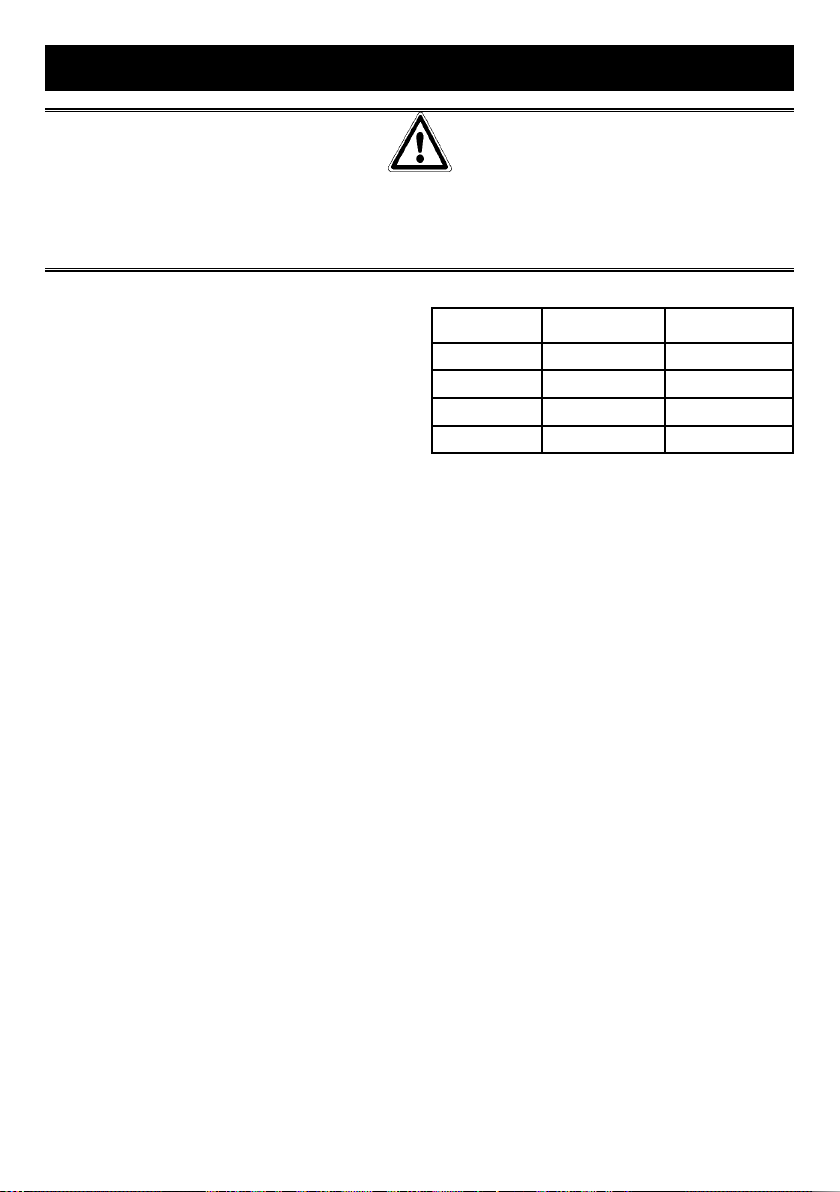
Uso dei bruciatori
Per ottenere il massimo della resa senza spreco
di gas è importante che il diametro della pentola
sia adeguato alla potenzialità del bruciatore (vedi
tabella seguente), in modo da evitare che la
fiamma esca dal fondo della pentola (fig. 2).
Utilizzare la portata massima per portare
rapidamente in ebollizzione i liquidi e quella ridotta
per riscaldare le vivande o per il mantenimento
dell’ebollizione.
Tutte le posizioni di funzionamento devono essere
scelte tra quelle di massimo e quella di minimo,
mai tra la posizione di massimo e il punto di
chiusura.
Per interrompere l’alimentazione gas ,ruotare
la manopola in senso orario sulla posizione di
chiusura.
In mancanza di energia elettrica è possibile
accendere i bruciatori con i fiammiferi posizionando
la manopola al punto di accensione (fiamma
grande fig. 1).
Bruciatori Potenze W Ø Pentole
Ausiliario 1000 10 - 14 cm
Semirapido 1650 16 - 18 cm
Rapido 3000 20 - 22 cm
Tripla corona 3500 24 - 26 cm
Avvertenze
- Controllare sempre che le manopole siano
nella posizione di chiuso (vedi fig.1) quando
l’apparecchiatura non è in funzione.
- In caso di spegnimento accidentale della fiamma
,la valvola di sicurezza,dopo qualche secondo,
interromperà automaticamente l’erogazione del
gas. Per ripristinare il funzionamento riportare
la manopola al punto di accensione ( fiamma
grande fig.1).
- Durante la cottura con grassi o olii, porre
la massima attenzione in quanto gli stessi,
surriscaldandosi, possono infiammarsi.
- Non utilizzare spray vicino all’apparecchio in
funzione.
- Non devono essere poste sul bruciatore pentole
instabili o deformate per evitare incidenti di
rovesciamento o trabocco.
- Assicurarsi che le maniglie delle pentole siano
posizionate correttamente.
- Quando si accende il bruciatore controllare che
la fiamma sia regolare , abbassare sempre la
fiamma o spegnerla prima di togliere le pentole.
4
Page 5
IT ISTRUZIONI PER L’UTENTE
PULIZIA
Prima di ogni operazione scollegare l’apparecchio dalla rete di alimentazione elettrica. Non
utilizzare pulitori a vapore per la pulizia dell’apparecchio.
Si consiglia di operare ad apparecchio freddo.
Pianale vetro e parti smaltate
Il pianale in vetro e tutte le parti smaltate devono
essere lavate con una spugna ed acqua saponata o
con detersivo leggero.
Non usare prodotti abrasivi o corrosivi.
Evitate che sostanze come succo di limone,
pomodoro, acqua salina, aceto, caffè e latte
rimangano a lungo sulle superfici smaltate.
Bruciatori e griglie
Questi pezzi possono essere tolti per facilitare la
pulizia.
I bruciatori devono essere lavati con una
spugna ed acqua saponata o con detersivo
leggero, ben asciugati e rimessi perfettamente
nel loro alloggiamento. Controllare che i canali
spartifiamma non siano ostruiti.
Vericare che la sonda della valvola di sicurezza e
l’elettrodo di accensione siano sempre ben puliti per
garantire un funzionamento ottimale.
Rubinetti a gas
L’eventuale lubrificazione dei rubinetti deve
essere eseguita esclusivamente da personale
specializzato.
In caso di indurimento o di anomalie di
funzionamento dei rubinetti gas chiamare il
Servizio di Assistenza.
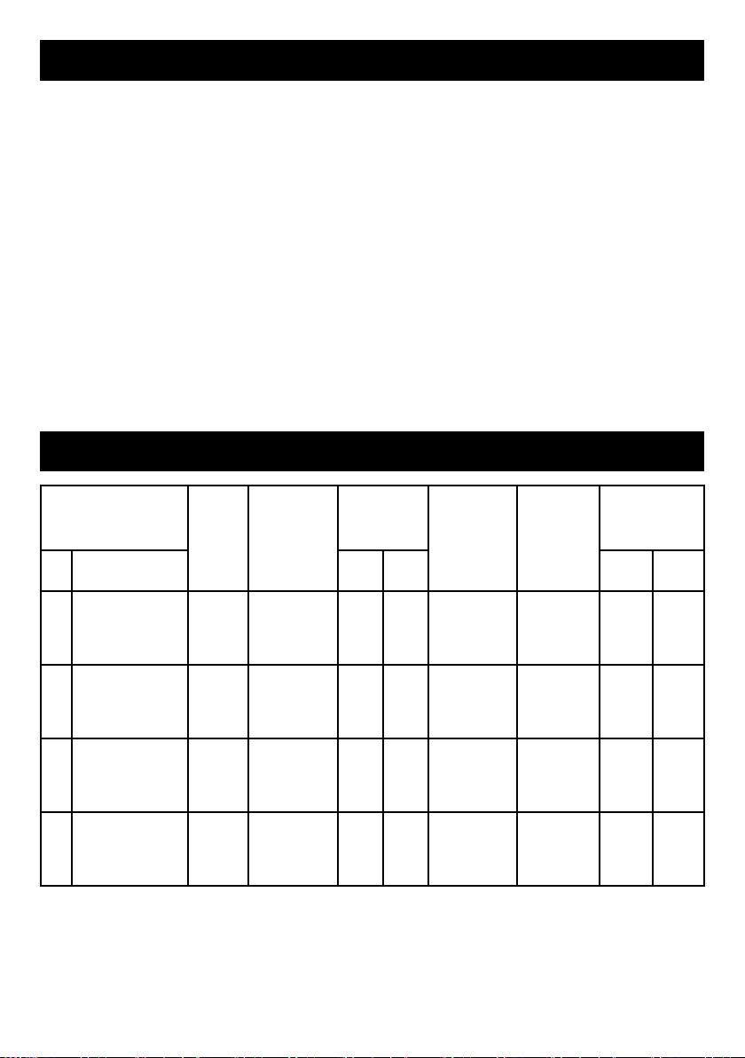
IT TABELLA CARATTERISTICHE TECNICHE
PO RTATA
TERMICA
(W)
BRUCIATORI
N°
DENOMINAZIONE
1 RAPIDO
2 SEMIRAPIDO
3 AUSILIARIO
TRIPLA
4
CORONA
PRESSIONE
GAS
G30 28-30 218 - 87 42 3000 950
G31 37 214 - 87 42 3000 950
G20 20 - 286 129 Reg. 3000 950
G30 28-30 120 - 65 31 1650 600
G31 37 118 - 65 31 1650 600
G20 20 - 157 97 Reg. 1650 600
G30 28-30 73 - 50 27 1000 450
G31 37 71 - 50 27 1000 450
G20 20 - 95 77 Reg. 1000 450
G30 28-30 255 - 94 60 3500 2100
G31 37 250 - 94 60 3500 2100
G20 20 - 334 141 Reg. 3500 2100
ESERCIZIO
mbar g/h L/h 1/100 mm 1/100 mm Max. Min.
PO RTATA
TERMICA
DIAMETRO
UGELLO
DIAMETRO
BY PASS
RUBINETTI
230 V~ 50/60 Hz
5
Page 6
IT ISTRUZIONI PER L’INSTALLATORE
AVVERTENZA IMPORTANTE
LE OPERAZIONI DI SEGUITO RIPORTATE DEVONO ESSERE ESEGUITE, NEL RISPETTO DELLE
NORME VIGENTI, ESCLUSIVAMENTE DA PERSONALE QUALIFICATO.
LA DITTA COSTRUTTRICE DECLINA OGNI RESPONSABILITA’ PER DANNI A PERSONE ANIMALI
O COSE DERIVANTI DALL’INNOSSERVANZA DI TALI DISPOSIZIONI.
INSTALLAZIONE
Montaggio del piano
L’apparecchio è costruito per essere incassato in
mobili resistenti al calore.
Le pareti dei mobili devono resistere ad una
temperatura di 65°C oltre a quella ambientale
secondo le normative europee EN 30 335-1-2-6.
L’apparecchio è di tipo “ Y “ , ovvero può essere
installato con una sola parete laterale a destra o a
sinistra del piano cottura.
Evitare l’installazione dell’apparecchiatura in
prossimità di materiali infiammabili come tendaggi,
canevacci, ecc.
Praticare un’apertura nel piano del mobile
delle dimensioni indicate nella fig.3 rispettando
una distanza di almeno 50 mm dal bordo
dell’apparecchio alle pareti adiacenti .
L’eventuale presenza di un pensile al di sopra del
piano cottura deve prevedere una distanza minima
dal top di 760 mm.
Si consiglia di isolare l’apparecchio dal mobile
sottostante con un separatore lasciando uno
spazio di depressione di almeno 10 mm. (fig.4).
Questo apparecchio è di classe 3.
Fissaggio del piano
Ogni piano di cottura viene corredato di una
speciale guarnizione con lato adesivo .
- Togliere dal piano griglie e bruciatori.
- Rovesciare l’apparecchio e stendere lungo il
bordo esterno del vetro la guarnizione adesiva
S (fig.5).
- Inserire e posizionare il piano cottura nell’apertura
praticata nel mobile e bloccarlo con le viti V dei
ganci di fissaggio G (fig. 6).
Locale di installazione
Questo apparecchio non è provvisto di
un dispositivo di scarico dei prodotti della
combustione, è necessario quindi scaricare
questi fumi all’esterno utilizzando una cappa o un
elettroventilatore che entri in funzione ogni volta
che si utilizza l’apparecchio.
Il locale dove viene installato l’apparecchio deve
avere un naturale afflusso d’aria per la regolare
combustione del gas e per la ventilazione del
locale ; il volume d’aria necessario non deve
essere inferiore a 20 m
L’afflusso dell’aria deve avvenire da aperture
permanenti praticate sulle pareti del locale
comunicanti con l’esterno.
La ventilazione può provvenire anche da un
locale attiguo , in questo caso attenersi a quanto
prescritto dalle norme UNI-CIG 7129 e 7131.
Le aperture dovranno avere una sezione minima
di 200 cm
Collegamento gas
Accertarsi che l’apparecchio sia predisposto
al tipo di gas disponibile, vedi l’etichetta sotto
l’apparecchio o quella riportata all’ultima pagina di
questo libretto.
Operare secondo le istruzioni riportate al paragrafo
“trasformazioni gas e regolazioni” per l’eventuale
adattamento a gas diversi.
L’apparecchio deve essere collegato all’impianto
gas utilizzando tubi metallici rigidi conformi alla
norma UNI-CIG 7129 o con tubi flessibili in acciaio
a parete continua conformi alla norma UNI-CIG
9891.
Il raccordo di entrata gas dell’apparecchio è
filettato ½ gas cilindrico maschio.
Il collegamento non deve provocare sollecitazioni
alla rampa gas.
Ad installazione ultimata controllare la tenuta dei
collegamenti con una soluzione saponosa.
2
.
3
.
6
Page 7

IT ISTRUZIONI PER L’INSTALLATORE
Collegamento elettrico
L’allacciamento alla rete elettrica deve essere
eseguito da personale qualificato e secondo le
norme vigenti.
La tensione dell’impianto elettrico deve
corrispondere a quelle indicata sulla etichetta sotto
l’apparecchio.
Verificare che l’impianto elettrico sia munito di un
efficace collegamento di terra secondo le norme
e le disposizioni di legge. La messa a terra è
obbligatoria.
Se l’apparecchio è sprovvisto di spina, applicare al
cavo di alimentazione una spina normalizzata.
Per il collegamento diretto alla rete, è
necessario prevedere un dispositivo che
assicuri la disconnessione dalla rete, con una
distanza di apertura dei contatti che consenta la
disconnessione completa nelle condizioni della
categoria di sovratensione III, conformemente alle
regole di installazione.
TRASFORMAZIONI GAS E REGOLAZIONI
Sostituzione ugelli
Se l’apparecchiatura risulta predisposta per
un diverso tipo di gas di quello disponibile è
necessario sostituire gli ugelli dei bruciatori.
La scelta degli ugelli da sostituire deve essere fatta
secondo la tabella “caratteristiche tecniche”.
Procedere quindi come segue:
- Togliere le griglie e i bruciatori.
- Con una chiave diritta L svitare l’ugello U (fig. 7)
e sostituirlo con quello corrispondente.
- Bloccare energicamente l’ugello.
MANUTENZIONE
Sostituzione cavo alimentazione
In caso di sostituzione del cavo di alimentazione si
dovrà utilizzare un cavo a norme del tipo H05VV-F
o H05RR-F di sezione 3 x 0,75 mm2.
Il collegamento alla morsettiera va eseguito come
illustrato in fig. 9:
cavetto L marrone (fase)
cavetto N blu (neutro)
cavetto
verde-giallo (terra)
Regolazione bruciatori
La regolazione del minimo deve essere sempre
corretta e la fiamma deve rimanere accesa anche
con un brusco passaggio dalla posizione di
massimo a quella di minimo.
Se questo non avviene è necessario regolare il
minimo come segue:
- Accendere il bruciatore;
- Ruotare il rubinetto fino alla posizione di minimo
(fiamma piccola);
- Sfilare la manopola dall’asta del rubinetto;
- Introdurre un cacciavite a taglio C nel foro F del
rubinetto (fig.8) e ruotare la vite by-pass fino ad
una corretta regolazione del minimo.
Per bruciatori funzionanti a gas G30 la vite bypass
deve essere avvitata completamente.
7
Page 8
CENTRI ASSISTENZA TECNICA
Per Assistenza Tecnica Autorizzata e Ricambi Originali rivolgersi al numero unico*
Numero unico
848 99 87 03
Oppure visitare il sito www.bompani.it
* al costo massimo di 2 centesimi di euro al minuto (iva inclusa) anche da cellulare.
CONDIZIONI DI GARANZIA
Le Condizioni di Garanzia sono consultabili sul nostro sito www.bompani.it
8
Page 9

GB INDEX
General notice p. 9
Instructions for the user p. 10
Using the burners p. 10
Cleaning p. 11
Technical characteristic tables p. 11
Instructions for the installer p. 12
Installation p. 12
Gas transformations and adjustments p. 13
Maintenance p. 13
Description of the cook-tops p. 32
Figures p. 33
Dear Customer,
We thank you and congratulate you on granting us your preference, by purchasing one of our products.
We are sure that this new appliance, manufactured with quality materials, will meet your requirements in
the best possible way.
The use of this new equipment is easy. However, we invite you to read this booklet carefully, before
installing and using the appliance.
This booklet gives the right information on the installation, use and maintenance, as well as useful advice.
THE MANUFACTURER
9
Page 10

GB GENERAL NOTICE
We invite you to read this instruction booklet carefully, before installing and using the equipment.
It is very important that you keep this booklet together with the equipment for any future
If this equipment should be sold or transferred to another person, make sure that the new user
receives the booklet, so that he can learn how to operate the appliance and read the
- The installation must be carried out by experienced and qualified personnel, in conformity with the
regulations in force.
- This equipment has been designed to be used by adults.
- This appliance is not intended for use by person (including children) with reduced physical, sensory or
mental capabilities, or lack of experience and knowledge, unless they have been given supervision or
instruction cencerning use of the appliance by a person responsible for their safety.
- Children should be supervised to ensure that they do not play with the appliance.
- Before powering the equipment, check that it is properly adjusted for the type of gas at disposal (see the
“installation” paragraph).
- Before carrying out the maintenance or cleaning the equipment, cut power supply off and make it cool
down.
- Make sure that air circulates around the gas equipment. Insufficient ventilation produces a lack of
oxygen.
- In case of an intense or prolonged use of the equipment, it may be necessary to improve aeration, for
example by opening a window or increasing the mechanical suction power, if it exists.
- The products of combustion must be discharged outside through a suction hood or an electric fan (see
the “installation” paragraph).
- For any possible operation or modification, apply to an authorized Technical Assistance Centre and
demand original spare parts.
consultation.
corresponding notice.
The manufacturer refuses all responsibility for possible damages to things or people, resulting
from a wrong installation or from an improper, incorrect or unreasonable use of this equipment.
This product complies with EU Directive 2002/96/EC.
The crossed-out dustbin symbol reported on the appliance indicates that the appliance must be disposed of
separately from other domestic refuse at the end of its useful life. It must therefore be delivered to a waste
recycling centre specically for electric and electronic equipment or returned to the retailer at the moment of
purchase of a new equivalent appliance.
The user is responsible for delivering the appliance to the appropriate collection centre at the end of its useful life, Failure to do so
may result in a ne, as provided for by laws governing waste disposal.
Differential collection of waste products for eventual recycling, treatment and environmentally friendly disposal helps reduce
possible negative effects on the environment and health, and also enables the materials making up the product to be recycled.
For more detailed information on the available refuse collection systems, refer to the local Municipal Solid Waste disposal centre
or the shop where the product was purchased.
Producers and importers are responsible for fullling their obligations as regards recycling, treatment and environmentally friendly
disposal by directly or indirectly participating in the collection system.
10
Page 11
GB INSTRUCTIONS FOR THE USER
It is necessary that all the operations regarding the installation, adjustment and adaptation
to the type of gas available are carried out by qualified personnel, in conformity
with the regulations in force. The specific instructions are described
in the booklet section intended for the installer.
USING THE BURNERS
The symbols silk-screen printed on the side of the
knob indicate the correspondence between the
knob and the burner.
Start-up without valves
Turn the corresponding knob anticlockwise up to
the maximum position (large flame, fig.1) and press
start-up button P (fig.1).
Automatic start-up with valves
Turn the corresponding knob anticlockwise up to
the maximum position (large flame, fig. 1) and press
the knob.
Once the burner has been started up, keep the
knob pressed for about 10 seconds.
Using the burners
In order to obtain the maximum yield without waste
of gas, it is important that the diameter of the pot is
suitable for the burner potential (see the following
table), so as to avoid that the flame goes out of the
pot bottom (fig. 2).
Use the maximum capacity to quickly make the liquids reach the boiling temperature, and the reduced
capacity to heat food or maintain boiling.
All of the operating positions must be chosen between the maximum and the minimum ones, never
between the minimum position and the closing
point.
The gas supply can be interrupted by turning the
knob clockwise up to the closing position.
If there is no power supply, it is possible to light the
burners with matches, setting the knob to the startup point (large flame, fig. 1).
Burners Power W Ø of pots
Auxiliary 1000 10 - 14 cm
Semi-rapid 1650 16 - 18 cm
Rapid 3000 20 - 22 cm
Triple ring 3500 24 - 26 cm
Notice
- When the equipment is not working, always
check that the knobs are in the closing position
(see fig.1).
- If the flame should blow out accidentally, the
safety valve will automatically stop the gas
supply, after a few seconds. To restore operation,
set the knob to the lighting point (large flame,
fig.1).
- While cooking with fat or oil, pay the utmost
attention as these substances can catch fire
when overheated.
- Do not use sprays near the appliance in
operation.
- Do not place unstable or deformed pots on the
burner, so as to prevent them from overturning or
overflowing.
- Make sure that pot handles are placed properly.
- When the burner is started up, check that the
flame is regular and, before taking pots away,
always lower the flame or put it out.
11
Page 12

GB INSTRUCTIONS FOR THE USER
CLEANING
Before any operation, disconnect the appliance
from the electric grid. Don’t use a steam
cleaner for the cleaning the hob.
It is advisable to clean the appliance when it is
cold.
Glass platform and enamelled part
The glass platform and all of the enamelled parts
must be washed with a sponge and soapy water or
with a light detergent.
Do not use abrasive or corrosive products.
Do not leave substances, such as lemon or tomato
juice, salt water, vinegar, coffee and milk on the
enamelled surfaces for a long time.
Burners and racks
These parts can be removed to make cleaning
easier.
The burners must be washed with a sponge and
soapy water or with a light detergent, wiped well
and placed in their housing perfectly. Make sure
that the flame-dividing ducts are not clogged.
Check that the feeler of the safety valve and the
start-up electrode are always perfectly cleaned, so
as to ensure an optimum operation.
Gas taps
The possible lubrication of the taps must be carried
out by specialized personnel, exclusively.
In case of hardening or malfunctions in the gas
taps, apply to the Customer Service.
GB TECHNICAL CARACTERISTIC TABLES
BURNERS
N°
DESCRIPTION
1 RAPID
2 SEMI-RAPID
3 AUXILIARY
4 TRIPLE RING
NORMAL
GAS
G30 28-30 218 - 87 42 3000 950
G31 37 214 - 87 42 3000 950
G20 20 - 286 129 Reg. 3000 950
G30 28-30 120 - 65 31 1650 600
G31 37 118 - 65 31 1650 600
G20 20 - 157 97 Reg. 1650 600
G30 28-30 73 - 50 27 1000 450
G31 37 71 - 50 27 1000 450
G20 20 - 95 77 Reg. 1000 450
G30 28-30 255 - 94 60 3500 2100
G31 37 250 - 94 60 3500 2100
G20 20 - 334 141 Reg. 3500 2100
PRESSURE
mbar g/h L/h 1/100 mm 1/100 mm Max. Min.
NOMINAL
RATE
INJECTOR
DIAMETER
TAP BY
PASS
DIAMETER
NOMINAL HEAT
INPUT (W)
230 V~ 50/60 Hz
12
Page 13

GB INSTRUCTIONS FOR THE USER
THE OPERATIONS INDICATED BELOW MUST BE FOLLOWED BY QUALIFIED PERSONNEL
EXCLUSIVELY, IN CONFORMITY WITH THE REGULATIONS IN FORCE.
THE MANUFACTURING FIRM REFUSES ALL RESPONSIBILITY FOR DAMAGES TO PEOPLE,
ANIMALS OR THINGS, RESULTING FROM THE FAILURE TO COMPLY WITH SUCH PROVISIONS.
INSTALLATION
Installing the top
The appliance is designed to be embedded into
heat-resistant pieces of furniture.
The walls of the pieces of furniture must resist a
temperature of 65°C besides the room one.
The equipment must not be installed near
inflammable materials, such as curtains, cloths,
etc.
Make a hole in the top of the piece of furniture,
with the dimensions indicated in fig.3, at a distance
of at least 50 mm from the appliance border to the
adjacent walls.
Any possible wall unit over the cook-top must be
placed at a distance of at least 760 mm from the
top.
It is advisable to isolate the appliance from the
piece of furniture below with a separator, leaving a
depression space of at least 10 mm (fig.4).
Fastening the top
Every cook-top is equipped with a special washer
having an adhesive side.
- Remove the racks and burners from the top
- Turn the appliance upside down and lay the
adhesive washer S along the external border of
the glass (fig.5).
- Introduce and place the cook-top in the hole
made in the piece of furniture, then block it with
the V screws of the fastening hooks G (fig.6).
IMPORTANT NOTICE
Installation room
This appliance is not provided with a device for
exhausting the products of combustion. Therefore,
it is necessary to discharge these smokes outside.
The room where this appliance is installed
must have a natural air inflow, so as to ensure
a regular gas combustion and room ventilation:
the necessary air volume must not be lower than
3
.
20m
Air must come from permanent openings made on
the room walls that communicate with the outside.
The section of these openings shall correspond to
at least 200 cm
Gas connection
Make sure that the appliance is adjusted for
the gas type available (see the label under the
appliance). Follow the instructions indicated in the
chapter “gas transformations and adjustments” for
the possible adaptation to different gases.
The appliance must be connected to the gas
system by means of still metal pipes or flexible
steel pipes having continuous walls, in compliance
with the regulations in force.
Gas enters the appliance through a cylindrical
threaded male gas union (1/2”).
The connection must not stress the gas ramp.
Once the installation is over, check the connection
seal with a soapy solution.
2
.
13
Page 14

GB INSTRUCTIONS FOR THE INSTALLER
Electric connection
The connection to the electric grid must be carried
out by qualified personnel and in conformity with
the regulations in force.
The voltage of the electric system must correspond
to the value indicated in the label under the
appliance. Make sure that the electric system is
provided with an effective ground connection in
compliance with the regulations and provisions of
the law. Grounding is compulsory.
GAS TRANSFORMATIONS AND
ADJUSTMENTS
Replacing the nozzles
If the equipment is adjusted for a type of gas that
is different from the one available, it is necessary
to replace the burner nozzles.
The choice of the nozzles to replace must be
made according to the table of the “technical
characteristics”.
Act as follows:
- Remove the racks and burners.
- by means of a straight spanner L, unscrew
the nozzle U (fig.7) and substitute it with the
corresponding one.
- tighten the nozzle strongly.
Adjusting the burners
The lowest flame point must always be properly
adjusted and the flame must remain on even if
there is an abrupt shift from the maximum to the
minimum position.
If this is not so, it is necessary to adjust the lowest
flame point as follows:
- start the burner up
- turn the tap up to the minimum position (small
flame)
- remove the knob from the tap rod
- introduce a flat-tip screwdriver C in the hole F of
the tap (fig.8) and turn the by-pass screw up to a
proper adjustment of the lowest flame point.
As regards propane gas burners, the by-pass
screw must be tightened completely.
MAINTENANCE
Replacing the power supply cable
If the power supply cable should be replaced,
it is necessary to use a cable with a section of
3x0.75m2, type H05VV-F or H05RR-F, complying
with the regulations in force.
The connection to the terminal board must be
effected as shown in fig. 9:
brown cable L (phase)
blue cable N (neutral)
green-yellow cable
(ground)
14
Page 15

FR INDEX
Avertissements généraux p. 15
Instructions pour l’utilisateur p. 16
Utilisation des brûleurs p. 16
Nettoyage p. 17
Tableau des caractéristiques techniques p. 17
Instructions pour l’installateur p. 18
Installation p. 18
Transformations gaz et réglages p. 19
Description des tables de cuisson p. 32
Figures p. 33
Cher Client,
Nous vous remercions pour la préférence que vous avez bien voulu nous accorder en achetant notre
produit et vous félicitons pour votre choix. Nous sommes certains que ce nouvel appareil, fabriqué avec
des matériaux de qualité, satisfera entièrement vos exigences.
L’utilisation de ce nouvel appareil est simple, nous vous invitons cependant à lire attentivement ce manuel
avant de l’installer et de l’utiliser.
En effet, ce manuel fournit les indications nécessaires pour l’installation, l’utilisation et l’entretien ainsi que
des conseils pratiques.
LE FABRICANT
15
Page 16

FR AVERTISSEMENTS GENERAUX
Nous vous invitons à lire ce manuel d’instructions avant d’installer et d’utiliser l’appareil. Il est
très important que ce manuel soit conservé avec l’appareil afin de pouvoir être consulté en
cas de besoin. Si l’appareil est vendu ou donné à une autre personne, il faut s’assurer que ce
manuel est donné en même temps, de façon à ce que le nouvel utilisateur soit informé sur son
Cet appareil est de classe 3 et a été conçu pour une utilisation de type non professionnel par des
- L’installation doit être effectuée par du personnel compétent et qualifié conformément aux normes en
vigueur.
- Cet appareil a été conçu pour être utilisé par des adultes.
- Cet appareil n’est pas prévu pour être utilisé par des personnes (y compris les enfants) dont les
capacités physiques, sensorielles ou mentales sont réduites, ou des personnes dénuées d’expérience
ou de connaissance, sauf si elles ont pu bénéficier, par l’intermédiaire d’une personne responsable de
leur sécurité, d’une surveillance ou d’instructions préalables concernant l’utilisation de l’appareil.
- Il convient de surveiller les enfants pour s’assurer qu’ils ne jouent pas avec l’appareil.
- Avant d’alimenter l’appareil, contrôler qu’il est correctement réglé pour le type de gaz à disposition (voir
paragraphe “Installation”).
- Avant l’entretien et le nettoyage, débrancher électriquement l’appareil et le laisser refroidir.
- S’assurer qu’il y a une circulation d’air autour de l’appareil au gaz. Une faible ventilation entraîne une
carence d’oxygène.
- Si l’appareil est utilisé de manière intense ou prolongée, il peut être nécessaire de prévoir une aération
supplémentaire, en ouvrant par exemple une fenêtre ou en augmentant la puissance de l’aspiration
mécanique si celle-ci existe.
- Les produits de la combustion doivent être évacués à l’extérieur avec une hotte aspirante ou un
ventilateur électrique (voir paragraphe “Installation”).
- Pour les éventuelles interventions ou modifications, s’adresser à un Centre d’Assistance Technique
agréé et exiger des pièces de rechange originales.
fonctionnement et prenne connaissance des avertissements correspondants.
particuliers à l’intérieur d’habitations.
Le fabricant décline toute responsabilité en cas de dommages aux choses ou aux personnes
dûs à une installation incorrecte ou à une utilisation inadéquate, erronée ou non raisonnable de
l’appareil.
Ce produit est conforme à la Directive EU 2002/96/EC.
Le logo «poubelle barrée» gurant sur l’appareil indique qu’au terme de son cycle de vie, cet appareil doit être,
non seulement traité séparément des déchets domestiques, mais aussi remis à un centre de récupération pour
équipements électriques et électroniques ou bien au revendeur lors de l’achat d’un appareil neuf équivalent.
Une fois l’appareil au terme de son cycle de vie, l’utilisateur est tenu de le remettre aux structures de récupération prévues à cet
effet, sous peine des sanctions prévues par la législation en vigueur en matière de déchets.
Une collecte sélective adéquate permettant d’envoyer l’équipement éliminé au recyclage, au traitement et à l’élimination compatible
sur le plan environnemental contribue à éviter de possibles effets négatifs sur l’environnement et la santé et facilite le recyclage
des matériaux dont le produit est constitué.
Pour plus de détails quant aux systèmes de récupération disponibles, s’adresser au service local chargé de l’élimination des
déchets ou au magasin où l’équipement a été acheté.
Les producteurs et les importateurs respecteront leurs obligations en vue du recyclage, du traitement et de l’élimination compatible
sur le plan environnemental aussi bien directement qu’en participant à un système collectif.
16
Page 17

FR INSTRUCTIONS POUR L’UTILISATEUR
Toutes les opérations relatives à l’installation, au réglage et à l’adaptation au type de gaz
disponible doivent être effectuées par du personnel qualifié, conformément aux normes en
Les instructions spécifiques sont reportées dans la partie du manuel réservée à l’installateur.
vigueur.
UTILISATION DES BRULEURS
Le symbole appliqué par sérigraphie à côté du
bouton indique à quel brûleur celui-ci correspond.
Allumage automatique sans soupape de
sécurité
Tourner dans le sens inverse des aiguilles d’une
montre le bouton correspondant jusqu’à la position
de maximum (grande flamme, fig. 1) et appuyer
sur le bouton.
Allumage automatique avec soupape de
sécurité
Tourner dans le sens inverse des aiguilles d’une
montre le bouton correspondant jusqu’à la position
de maximum (grande flamme, fig. 1) et appuyer
sur le bouton.
Une fois l’allumage obtenu, maintenir le bouton
appuyé pendant environ 10 secondes.
Utilisation des brûleurs
Pour obtenir un rendement optimal sans gaspillage
de gaz, il est important que le diamètre de la
casserole soit adapté au potentiel du brûleur (voir
tableau ci-après), de façon à éviter que la flamme
sorte du fond de la casserole (fig. 2).
Utiliser le débit maximal pour amener rapidement
à ébullition les liquides et le débit réduit pour
réchauffer les aliments ou pour maintenir
l’ébullition.
Toutes les positions de fonctionnement doivent
être choisies entre celles de maximum et de
minimum et jamais entre celle de maximum et le
point de fermeture.
Pour interrompre l’alimentation en gaz, tourner le
bouton dans le sens des aiguilles d’une montre
jusqu’à la position de fermeture.
En cas d’absence d’énergie électrique, il est
possible d’allumer les brûleurs avec des allumettes
en positionnant le bouton sur le point d’allumage
(grande flamme, fig. 1).
Brûleurs Puissante W Ø Casseroles
Auxiliaire 1000 10 - 14 cm
Semi-rapide 1650 16 - 18 cm
Rapide 3000 20 - 22 cm
Triple
couronne
Avertissements
- Contrôler toujours que les boutons sont sur la
position “fermé” (voir fig. 1) quand l’appareil ne
fonctionne pas.
- Si la flamme s’éteint accidentellement, après
quelques secondes, la soupape de sécurité
interrompt automatiquement l’arrivée du gaz.
- Pour rétablir le fonctionnement, reporter le bouton
au point d’allumage (grande flamme, fig. 1).
- Pendant la cuisson avec des graisses et des
huiles, faire particulièrement attention car
cellesci, si elles sont surchauffées, peuven
s’enflammer.
- Ne pas utiliser de vaporisateurs près de l’appareil
en fonction.
- Il ne faut pas poser sur les brûleurs des
casseroles instables ou déformées afin
d’éviter des accidents de renversement ou de
débordement.
- S’assurer que les poignées des casseroles soient
positionnées correctement.
- Quand on allume le brûleur, contrôler que la
flamme est régulière; abaisser toujours la flamme
ou l’éteindre avant d’enlever la casserole.
3500 24 - 26 cm
17
Page 18

FR INSTRUCTIONS POUR L’UTILISATEUR
NETTOYAGE
Brûleurs et grilles
Ces parties peuvent être enlevées pour faciliter le
Avant toute opération de nettoyage, débrancher
l’appareil du réseau d’alimentation électrique.
N’utilisez jamais d’appareils à vapeur ou à
haute pression pour nettoyer le four (exigences
relatives à la sécurité électrique).
Il est conseillé d’opérer quand l’appareil est froid.
nettoyage.
Les brûleurs doivent être nettoyés avec une
éponge et de l’eau savonneuse ou avec un
détergent léger, bien essuyés et remis parfaitement
dans leur siège.
Contrôler que les canaux de répartition des
flammes ne sont pas bouchés.
Plan en verre et parties émaillées
Le plan en verre et les parties émaillées doivent
être nettoyés avec une éponge et de l’eau
Vérifier que la sonde de la soupape de sécurité et
l’électrode d’allumage sont toujours bien propres
afin de garantir un fonctionnement optimal.
savonneuse ou avec un détergent léger.
Ne pas utiliser de produits abrasifs ou corrosifs.
Eviter que les substances comme le jus de citron,
la tomate, l’eau salée, le vinaigre, le café et le
lait restent pendant longtemps sur les surfaces
émaillées.
Robinets de gaz
L’éventuel graissage des robinets doit être effectué
exclusivement par du personnel spécialisé.
Si les robinets de gaz deviennent difficiles à
tourner ou ont un fonctionnement anormal, appeler
le Service d’Assistance.
FR TABLE DE CARATERISTIQUES TECHNIQUES
BRULEURS
N° DESIGNATION
GAZ
PRESSION
DE SERVICE
DEBIT
DIAMÈTRE
INJECTEUR
DIAMÈTRE
BY PASS
ROBINET
mbar g/h L/h 1/100 mm 1/100 mm Max. Min.
DEBITS
CALORIFIQUES
(W)
1 RAPIDE
2 SEMI-RAPIDE
3 AUXILIAIRE
TRIPLE
4
COURONNE
230 V~ 50/60 Hz
G30 28-30 218 - 87 42 3000 950
G31 37 214 - 87 42 3000 950
G20 20 - 286 129 Reg. 3000 950
G25 25 - 332 132 Reg. 3000 950
G30 28-30 120 - 65 31 1650 600
G31 37 118 - 65 31 1650 600
G20 20 - 157 97 Reg. 1650 600
G25 25 - 183 100 Reg. 1650 600
G30 28-30 73 - 50 27 1000 450
G31 37 71 - 50 27 1000 450
G20 20 - 95 77 Reg. 1000 450
G25 25 - 111 80 Reg. 1000 450
G30 28-30 255 - 94 60 3500 2100
G31 37 250 - 94 60 3500 2100
G20 20 - 334 141 Reg. 3500 2100
G25 25 - 388 141 Reg. 3500 2100
18
Page 19

FR INSTRUCTIONS POUR L’UTILISATEUR
LES OPERATIONS REPORTEES CI-APRES DOIVENT ETRE EXECUTEES DANS LE RESPECT
DES NORMES EN VIGUEUR, EXCLUSIVEMENT PAR DU PERSONNEL QUALIFIE. LE FABRICANT
DECLINE TOUTE RESPONSABILITE POUR LES DOMMAGES AUX PERSONNES, ANIMAUX ET
CHOSES DERIVANT DU NON-RESPECT DE CES DISPOSITIONS.
INSTALLATION
Montage de la table de cuisson
L’appareil est fabriqué pour être encastré dans des
meubles résistant à la chaleur.
Les parois des meubles doivent résister à une
température de 65°C en plus de la température
ambiante, conformément aux normes européennes
EN 30 335-1-2-6.
L’appareil est de type “Y”, c’est-à-dire qu’il peut
être installé avec une seule paroi latérale, à droite
ou à gauche de la table de cuisson.
Eviter d’installer l’appareil à proximité de matériaux
inflammables comme des rideaux, des torchons,
etc..
Pratiquer une ouverture, dans le plateau du
meuble, des dimensions indiquées en fig. 3, en
respectant une distance d’au moins 50 mm entre
le bord de l’appareil et les parois voisines.
En cas de présence d’une armoire murale
audessus de la table de cuisson, il faut prévoir une
distance minimale de 760 mm entre celle-ci et le
plan de travail.
Il est conseillé d’isoler l’appareil du meuble se
trouvant au-dessous avec un séparateur en
laissant un espace de dépression d’au moins 10
mm (fig. 4).
Cet appareil est de classe 3.
Fixation de la table de cuisson
Chaque table de cuisson est accompagnée d’un
joint spécial avec côté adhésif.
- Enlever les grilles et les brûleurs de la table de
cuisson.
- Retourner l’appareil et appliquer le joint adhésif S
le long du bord externe du verre (fig. 5).
- Insérer et positionner la table de cuisson dans
l’ouverture pratiquée dans le meuble et la bloquer
avec les vis V des crochets de fixation G (fig. 6).
AVERTISSEMENT IMPORTANT
Pièce d’installation
Cet appareil n’est pas équipé d’un dispositif
d’évacuation des produits de la combustion ; il
est donc nécessaire d’évacuer les fumées vers
l’extérieur en utilisant une hotte ou un ventilateur
électrique qui soit mis en marche à chaque fois
que l’on utilise l’appareil.
La pièce où est installé l’appareil doit avoir un
afflux d’air naturel pour la combustion régulière
du gaz et pour la ventilation de la pièce: le volume
d’air nécessaire ne doit pas être inférieur à 20m
L’afflux d’air doit s’effectuer par une ouverture
permanente pratiquée sur les murs de la pièce et
communicante avec l’extérieur.
La ventilation peut également provenir d’une pièce
contiguë, dans ce cas respecter les normes en
vigueur à ce sujet.
Les ouvertures doivent avoir une section minimale
de 200 cm
Branchement gaz
S’assurer que l’appareil est adéquat pour le type
de gaz disponible; pour cela se référer à l’étiquette
placée sous l’appareil ou à celle reportée sur la
dernière page de ce manuel.
Opérer conformément aux instructions reportées
au paragraphe “transformations gaz et réglages”
pour l’éventuelle adaptation à des gaz différents.
L’appareil doit être raccordé à l’installation du gaz
en utilisant des tubes métalliques rigides ou avec
des tuyaux flexibles en acier à paroi continue
conformes aux normes en vigueur.
Le raccord d’entrée gaz de l’appareil est fileté ½
gaz cylindrique mâle.
Le raccordement ne doit pas provoquer de
sollicitations à la rampe de gaz.
Une fois l’installation terminée, contrôler
l’étanchéité des raccordements avec une solution
savonneuse.
2
.
3
.
19
Page 20

FR INSTRUCTIONS POUR L’UTILISATEUR
Branchement électrique
Le branchement au réseau électrique doit être
exécuté par du personnel qualifié conformément
aux normes en vigueur.
La tension de l’installation électrique doit
correspondre à celle indiquée sur l’étiquette
située sous l’appareil. Vérifier que l’installation
est équipée d’un branchement à la terre efficace
conformément aux normes et aux dispositions de
loi. La mise à la terre est obligatoire.
Si l’appareil est sans fiche, appliquer au câble
d’alimentation une fiche normalisée.
Cet appareil doit être place à une distance
raisonnable afin de pouvoir être débranché en cas
de survoltage (catégorie III), en accord avec les
règles d’installation.
TRANSFORMATIONS GAZ ET
REGLAGES
Remplacement des buses
Si l’appareil est prévu pour un type de gaz différent
de celui disponible, il faut remplacer les buses des
brûleurs.
Le choix des buses à remplacer doit être fait selon
le tableau “caractéristiques techniques”.
Procéder ensuite de la manière suivante :
- Enlever les grilles et les brûleurs.
- Avec une clé droite L, dévisser la buse U (fig. 7)
et la remplacer par la buse adéquate.
- Bloquer énergiquement la buse.
ENTRETIEN
Remplacement câble d’alimentation
En cas de remplacement du câble d’alimentation, il
faut utiliser un câble conforme aux normes du type
H05VV-F ou H05RR-F de section 3 x 0,75 mm2.
Le branchement au bornier doit être effectué
comme indiqué en fig. 9:
câble L marron (phase)
câble N bleu (neutre)
câble
vert-jaune (terre)
Réglage des brûleurs
Le réglage du minimum doit toujours être correct
et la flamme doit toujours rester allumée même en
cas de passage rapide de la position de maximum
à celle de minimum.
Si ce n’est pas le cas, il faut régler le minimum de
la manière suivante :
- Allumer le brûleur ;
- Tourner le robinet jusqu’à la position de minimum
(petite flamme) ;
- Enlever le bouton de la tige du robinet ;
- Introduire un tournevis à pointe plate C dans le
trou F du robinet (fig. 8) et tourner la vis by-pass
jusqu’au réglage correct du minimum.
Pour les brûleurs fonctionnant au gaz G30, la vis
by-pass doit être complètement vissée.
20
Page 21

DE INHALT
Allgemeine Hinweise seite 21
Anleitungen für den Gebraucher seite 22
Gebrauch der Brenner seite 22
Reinigung seite 23
Tabelle der technischen Daten seite 23
Anleitungen für den Installateur seite 24
Einbau seite 24
Gasumstellung und Einstellungen seite 25
Beschreibung der Kochmulden seite 32
Abbildungen seite 33
Verehrter Kunde,
wir danken Ihnen für Ihren Vorzug und beglückwünschen Sie zum Kauf unseres Produkts. Wir sind
sicher, daß dieses neue, aus hochwertigen Baustoffen hergestellte Gerät, allen Ihren Anforderungen
entsprechen wird.
Der Gebrauch des Geräts ist einfach. Trotzdem bitten wir Sie, die vorliegenden Anleitungen vor dem
Einbau und dem Gebrauch aufmerksam durchzulesen.
In den Anleitungen sind die korrekten Anweisungen für den Einbau, den Gebrauch und die Wartung sowie
weitere, nützliche Empfehlungen enthalten.
DER HERSTELLER
21
Page 22

DE ALLGEMEINE HINWEISE
Wir bitten Sie, die vorliegenden Anleitungen vor dem Einbau und Gebrauch des Geräts zu lesen.
Es ist sehr wichtig, daß das Handbuch auch in Zukunft verfügbar ist; deshalb sollte es in
der Nähe des Geräts aufbewahrt werden. Bei Weiterverkauf oder Drittabtretung des Geräts
sind die Anleitungen mitzuliefern, damit sich der neue Gebraucher über den Betrieb und die
Das vorliegende Gerät gehört zur Klasse 3 und wurde für einen nicht berufsmäßigen
- Die Installation muß von qualifiziertem Fachpersonal nach den geltenden Vorschriften vorgenommen
werden.
- Das Gerät ist von Erwachsenen zu bedienen.
- Dieses Gerät ist nicht bestimmt für die Benutzung durch Personen (einschließlich Kinder) mit
eingeschränkten psychischen oder motorischen Fähigkeiten, oder mit fehlender Erfahrung und
fehlendem Wissen, außer dass sie bezüglich der Benutzung des Geräts der Aufsicht und Anleitung
einer Person unterliegen, die für ihre Sicherheit verantwortlich ist.
- Kinder müssen überwacht werden, um sicher zu gehen, dass sie nicht mit dem Gerät spielen.
- Vor der Speisung des Geräts ist die Übereinstimmung mit der verfügbaren Gasart der Zuleitung zu
kontrollieren (siehe Abschnitt “Einbau”).
- Vor allen Wartungs- und Reinigungseingriffen muß das Gerät ausgesteckt und abgekühlt werden.
- Stellen Sie eine ausreichende Luftzirkulation rund um das Gasgerät sicher. Bei unzureichender
Entlüftung kann es zu einem Sauerstoffmangel kommen.
- Bei intensivem oder lang anhaltendem Gebrauch des Geräts kann eine zusätzliche Entlüftung
erforderlich werden, die beispielsweise durch Öffnen eines Fensters oder Erhöhen der Leistung der
eventuell vorhandenen, mechanischen Entlüftungsanlage erzielt werden kann.
- Die Verbrennungsprodukte müssen durch eine Abzugshaube oder einen Elektrobelüfter ins Freie
abgeleitet werden (siehe Abschnitt “Einbau”).
- Alle Eingriffe und Änderungen dürfen ausschließlich von einer ermächtigten Kundendienststelle
durchgeführt werden.Verlangen Sie nur Original-Ersatzteile!
entsprechenden Hinweise informieren kann.
Hausgebrauch durch Privatpersonen entwickelt.
Der Hersteller weist jegliche Haftung für eventuelle Schäden an Personen und Sachen von sich,
die auf den nicht korrekten Einbau oder uneigenen oder unvernünftigen Gebrauch des Geräts
zurückgehen.
Dieses Produkt ist konform mit der EG-Richtlinie 2002/96/EG.
Das Symbol des durchgestrichenen Abfallbehälters weist darauf hin, dass das Produkt am Ende seines Lebens
als Sondermüll durch ein Entsorgungsunternehmen für elektrische und elektronische Altgeräte entsorgt oder beim
Einkauf eines neuen, gleichwertigen Geräts dem Händler übergeben werden muss.
Der Benutzer ist dafür verantwortlich, dass das Gerät am Ende seines Lebens den entsprechenden Sammelstellen übergeben
wird, andernfalls können laut einschlägigem Abfallbeseitigungsgesetz Geldstrafen verhängt werden.
Die differenzierte Sammlung von Altgeräten und deren Weiterverwertung, Behandlung und umweltverträgliche Beseitigung trägt
dazu bei, die Schadstoffbelastungen von Umwelt und Gesundheit zu verringern und die Weiterverwendung der Baumaterialien
zu fördern.
Für nähere Informationen zu den verfügbaren Sammelverfahren wenden Sie sich bitte an die lokale Entsorgungsstelle oder an den
Händler, der Ihnen das Gerät verkauft hat.
Hersteller und Importeure üben ihre Verantwortung für die Weiterverwertung, Behandlung und umweltverträgliche Beseitigung
direkt aus, oder indem sie an einem kollektiven Sammelverfahren teilnehmen.
22
Page 23

DE ANLEITUNGEN FÜR DEN GEBRAUCHER
ALLE EINBAU-, EINSTELL- UND UMSTELLVORGÄNGE AUF DIE VERFÜGBARE GASART MÜSSEN
VON FACHPERSONAL NACH DEN GELTENDEN VORSCHRIFTEN VORGENOMMEN WERDEN.
DIE SPEZIFISCHEN ANLEITUNGEN SIND IM ABSCHNITT DIESES HANDBUCHES ENTHALTEN,
WELCHER DEM INSTALLATIONSPERSONAL VORBEHALTEN IST.
GEBRAUCH DER BRENNER
Die mit Siebdruck seitlich an den
Bedienungsknöpfen angebrachten Symbole zeigen
die Übereinstimmung zwischen Brenner und Knopf
an.
Automatische Zündung ohne Sicherheitsventil
Gewünschten Bedienungsknopf entgegen dem
Uhrzeigersinn auf die große Flamme drehen (Abb.
1) und Knopf drücken.
Automatische Zündung mit Sicherheitsventil
Gewünschten Bedienungsknopf entgegen dem
Uhrzeigersinn auf die große Flamme drehen (Abb.
1) und Knopf drücken.
Nach erfolgter Zündung muß der Bedienungsknopf
noch 10 Sekunden lang gedrückt bleiben.
Gebrauch der Brenner
Um maximale Leistungen ohne
Energieverschwendung zu erzielen, muß der
fannendurchmesser der Leistung des Brenners
angepaßt sein (siehe nachstehende Tabelle).
Die Flamme sollte möglichst nicht über den
Pfannenrand hinaus reichen (Abb. 2).
Die große Flamme wird zum Erhitzen von
Flüssigkeiten verwendet, die kleine zum
Aufwärmen oder Warmhalten von Speisen.
Alle Betriebspositionen sind zwischen der großen
und kleinen Flamme zu wählen und auf keinen
Fall zwischen der großen Flamme und dem
Ausschaltpunkt.
Die Gaszufuhr wird durch Drehen des
Bedienungsknopfes im Uhrzeigersinn auf die
Nullanzeige unterbrochen.
Bei Stromausfall können die Brenner mit
Streichhölzern gezündet werden, indem man den
Bedienungsknopf auf die große Flamme (Abb. 1)
dreht.
Brenner Leistung in W Pfannen Ø
Hilfsbrenner 1000 10 - 14 cm
Mittlerer Brenner 1650 16 - 18 cm
Schnell Brenner 3000 20 - 22 cm
Ultra-stark
Hinweise
- Stellen Sie immer sicher, daß die
Bedienungsknöpfe auf Null stehen (siehe Abb.
1), wenn das Gerät nicht in Betrieb ist.
- Beim zufälligen Erlöschen der Flamme wird die
Gaszufuhr durch das Sicherheitsventil nach
einigen Sekunden automatisch unterbrochen.
Um den Betrieb wieder herzustellen, wird der
Bedienungsknopf wieder auf die große Flamme
(Abb. 1) gedreht.
- Beim Kochen mit Fetten und Ölen ist Vorsicht
walten zu lassen, weil sich diese bei großer Hitze
entzünden könnten.
- Verwenden Sie keine Sprays in der Nähe des
betriebenen Geräts.
- Stellen Sie keine verformten oder unstabilen
Pfannen auf die Brenner, die kippen oder
überlaufen könnten.
- Versichern Sie sich, daß die Handgriffe der
Pfannen korrekt positioniert sind.
- Beim Zünden eines Brenners ist zu prüfen,
daß die Flamme regelmäßig brennt; Flamme
zurückbzw. abschalten, wenn man die Pfannen
abnimmt.
3500 24 - 26 cm
23
Page 24

DE ANLEITUNGEN FÜR DEN GEBRAUCHER
REINIGUNG
Vor jedem Eingriff ist die elektrische Versorgung
des Geräts auszuschalten. Keine Dampfreiniger zur
Reinigung des Geräts verwenden.
Es empfiehlt sich, erst mit dem Eingriff zu beginnen, wenn
das Gerät abgekühlt ist.
Glasfläche und emaillierte Teile
Die Glasoberfläche und alle emaillierten Teile müssen
mit einem Schwamm und Seifenwasser bzw. mit einem
leichten Reinigungsmittel gereinigt werden.
Verwenden Sie keine schleifenden oder korrosiven
Produkte.
Verhindern Sie, daß Substanzen wie Zitronensaft,
Tomaten, Salzwasser, Essig, Kaffee oder Milch lange auf
den emaillierten Flächen bleiben.
Brenner und Topfroste
Diese Teile können zur Reinigung problemlos
abgenommen werden. Die Brenner sind mit einem
Schwamm und Seifenwasser bzw. mit einem leichten
Reinigungsmittel zu reinigen, gut zu trocknen und wieder
perfekt in ihren Sitzen einzurasten. Kontrollieren Sie, daß
die Flammenkränze nicht verstopft sind.
Kontrollieren Sie auch, daß die Sonde des
Sicherheitsventils und die Einschaltelektrode immer
sauber sind, um einen optimalen Betrieb zu gewährleisten.
Gashähne
Die Schmierung der Gashähne darf ausschließlich von
Fachpersonal vorgenommen werden.
Bei Verhärtungen oder Betriebsstörungen der Gashähne
wenden Sie sich bitte an den Kundendienst.
DE TABELLE DER TECHNISCHEN DATEN
GASBRENNER
N° BEZEICHNUNG mbar g/h L/h 1/100 mm 1/100 mm Max. Min.
1
SCHNELL
2
MITTLERER
3
HILFSL
ULTRA-
4
STARK
GAS
G30/G31
G30/G31
G30/G31
G30/G31
DRUCK
G20
G25
G20
G25
G20
G25
G20
G25
THERMISCHER
DRUCK
50 218 79 42 3000 950
20 286 129 Adjust. 3000 950
20 332 138 Adjust. 3000 950
50 127 58 31 1650 600
20 167 97 Adjust. 1650 600
20 194 105 Adjust. 1650 600
50 73 46 27 1000 450
20 95 77 Adjust. 1000 450
20 111 85 Adjust. 1000 450
50 276 83 60 3500 2100
20 361 141 Adjust. 3500 2100
20 421 150 Adjust. 3500 2100
DURCHMESSER
DÜSE
DURCHMESSER
BY PASS
GASHAHN
THERMISCHE
LEISTUNG
(W)
230 V~ 50/60 Hz
24
Page 25

DE ANLEITUNGEN FÜR DEN INSTALLATEUR
ALLE NACHSTEHENDEN VORGÄNGE DÜRFEN NACH DEN GELTENDEN VORSCHRIFTEN
AUSSCHLIESSLICH VON FACHPERSONAL VORGENOMMEN WERDEN.
DIE HERSTELLERFIRMA WEIST JEGLICHE VERANTWORTUNG FÜR SCHÄDEN AN PERSONEN,
TIEREN ODER SACHEN BEI NICHTBEACHTUNG DIESER ANWEISUNGEN VON SICH.
EINBAU
Montage der Kochmulde
Das Gerät ist für den Einbau in hitzebeständige
Untermöbel bestimmt.
Die Möbelwände müssen einer
Temperatur standhalten, die 65°C über der
Umgebungstemperatur liegt (europäische Normen
EN 30 335-1-2-6).
Das Gerät entspricht dem Typ “Y” und kann also
nur mit einer Seite rechts oder links der Kochmulde
installiert werden.
Vermeiden Sie den Einbau des Geräts in der
Nähe von brennbaren Materialien, wie Vorhängen,
Küchentüchern, usw.
Möbeloberfläche gemäß den in Abb. 3 angeführten
Abmessungen ausschneiden. Dabei ist ein
Mindestabstand von 50 mm vom Geräterand zu
den umliegenden Wänden einzuhalten.
Das eventuelle Vorhandensein eines
Hängeschrankes über der Kochfläche setzt einen
Mindestabstand von 760 mm voraus.
Das Gerät muß vom darunterliegenden Möbel
durch eine Trennung isoliert werden, bei welcher
ein Depressionsraum von mindestens 10 mm
vorzusehen ist (Abb. 4).
Das vorliegende Gerät entspricht der Klasse 3.
Festmachen der Kochmulde
Jeder Kochmulde liegt eine Spezialdichtung mit
Klebeseite bei.
- Roste und Brenner von der Kochplatte
abnehmen
- Den Apparat umdrehen und die Haftdichtung
S entlang des äußeren Rands der Glasplatte
anbringen (Abb. 5)
- Die Kochplatte innerhalb der im Möbel
ausgeschnittenen Öffnung einsetzen und
positionieren und sie mit den V- Schrauben der
Befestigungshaken G feststellen (Abb. 6)
WICHTIGER HINWEIS!
entstehenden Abgase durch eine Abzugshaube
oder einen Elektroentlüfter ins Freie abgeleitet
werden, die immer dann in Betrieb genommen
werden, wenn man das Gerät verwendet.
Das Installationslokal muß über einen natürlichen
Luftzufluß zur regelmäßigen Gasverbrennung und
Entlüftung des Lokals verfügen. Das erforderliche
Luftvolumen darf nicht unter 20 m
Der Luftzufluß muß durch permanente Öffnungen
in den Wänden des Lokals gewährleistet werden,
die ins Freie führen.
Die Entlüftung kann auch von einem Nebenlokal
kommen. In diesem Fall sind die geltenden
Vorschriften zu berücksichtigen.
Die Öffnungen muüssen einen Mindestschnitt von
2
200 cm
Gasanschluß
Versichern Sie sich, daß das Gerät für die
verfügbare Gasart vorbereitet ist - siehe Schild
unter dem Gerät oder auf der letzten Seite dieser
Anleitungen.
Die eventuelle Anpassung an verschiedene,
andere Gasarten ist gemäß den Anleitungen des
Absatzes “Gasumstellung und Einstellungen”
vorzunehmen.
Das Gerät ist an die Gasanlage durch steife
Metallrohre oder flexible Stahlrohre mit
durchgehenden Wänden gemäß den geltenden
Vorschriften anzuschließen.
Der Gasanschluß des Geräts ist ein Gas- Gewinde-
Zylindersteckanschluß.
Die Verbindung darf zu keinen
Gasrampenbeanspruchungen führen.
Nach erfolgtem Anschluß ist die Dichtheit der
Anschlüsse mit einer Seifenlösung zu prüfen.
aufweisen.
3
liegen.
Einbaulokal
Dieses Gerät verfügt über keine Auslaßvorrichtung
der Verbrennungsprodukte. Daher müssen die
25
Page 26

DE ANLEITUNGEN FÜR DEN INSTALLATEUR
Elektrischer Anschluß
Der Stromanschluß ist von Fachpersonal nach den
geltenden Vorschriften vorzunehmen.
Die Spannung der Stromanlage muß mit der
Angabe auf dem Schild unter dem Gerät
übereinstimmen.
Sicherstellen, daß die Stromanlage gemäß den
gesetzlichen Vorschriften und Verordnungen mit
einer effizienten Erdungsanlage ausgestattet ist.
Die Erdung ist bindend vorgeschrieben.
Wenn das Gerät ohne Stecker geliefert wird, ist ein
Standardstecker am Speisekabel anzubringen.
Zum Direktanschluss an das Stromnetz ist es
erforderlich, dass ein Schalter vorgesehen
ist, der die völlige Trennung von Stromnetz
sicherstellt, mit einer Kantaktöffnungsweite die der
Überspannungskategorie III entspricht und den
örtlichen Installationsvorschriften entsprechend
angebracht wird.
GASUMSTELLUNGEN UND
EINSTELLUNGEN
Austausch der Düsen
Wenn das Gerät für eine andere als der
verfügbaren Gasart vorbereitet ist, müssen die
Düsen der Brenner ersetzt werden.
Die Wahl der auszutauschenden Düsen ist aus der
Tabelle der “Technischen Daten” ersichtlich.
Vorgehensweise:
- Topfroste und Brenner abnehmen.
- Mit einem geraden Schlüssel L Düse U aufdrehen
(Abb. 7) und durch die entsprechende Düse
ersetzen.
- Düse fest zudrehen.
WARTUNG
Austausch des Speisekabels
Bei Austausch des Speisekabels muß ein
Normkabel des Typs H05VV-F oder H05RR-F
mit einem Schnitt von 3 x 0,75 mm2 verwendet
werden.
Der Anschluß an das Klemmenbrett wird gemäß
Abb. 9 vorgenommen:
Braunes Kabel L (Phase)
Blaues Kabel N (Nulleiter)
Gelb-grünes Kabel
(Erde)
Einstellung der Brenner
Die Einstellung der kleinen Flamme muß immer
korrekt vorgenommen werden: die Flamme muß
auch bei einer schnellen Bewegung von der großen
auf die kleine Flamme eingeschaltet bleiben.
Sollte dies nicht der Fall sein, muß die kleine
Flamme wie folgt eingestellt werden:
- Brenner einschalten.
- Bedienungsknopf vom Stab des Hahnes
abziehen;
- Schraubenzieher C in die Öffnung F des Hahnes
einführen (Abb. 8) und das Umleitventil solange
drehen, bis eine korrekte Einstellung der kleinen
Flamme erzielt ist.
Für die Brenner mit Gas G30 - Betrieb muß die
Umleitschraube kann zugeschraubt werden.
26
Page 27

RUS
ОГЛАВЛЕНИЕ
Общие замечания ........................................................................................... стр. 27
Инструкции для пользователя ................................................................... стр. 28
Пользование горелками ................................................................................. стр. 28
Чистка ............................................................................................................ стр. 29
Таблицы технических характеристик ...................................................... стр. 29
Инструкции для установщика .................................................................... стр. 30
Установка ....................................................................................................... стр. 30
Изменение газа и регулирование .................................................................. стр. 31
Óõîä .................................................................................................................. ñòð. 31
Описание плит ............................................................................................... стр. 32
Ðècóíkè ............................................................................................................ ñòð. 33
Уважаемый клиент,
благодарим Вас и поздравляем за предпочтение предоставленное нам при покупке нашей
продукции. Мы уверены, что это новое устройство, выполненное из качественных материалов,
удовлетворит наилучшим образом Вашим требованиям.
Употреблять эту новую продукцию легко, несмотря на это мы Вас приглашаем внимательно
прочесть эту книгу до устанавливания и использования устройства.
Книга предоставляет точные указания по устанавливанию, употреблению и уходу, помимо
предоставления полезных советов.
ИЗГОТОВИТЕЛЬ
27
Page 28

RUS
ОБЩИЕ ЗАМЕЧАНИЯ
Устанавливание должно быть произведено опытными и квалифицированными работниками, в
соответствии с существующими нормами.
Данные устройства были созданы для взрослых пользователей.
Таким образом, будьте внимательны, чтобы дети не приближались с целью игры.
Смотреть за детьми во время функционирования устройства, чтобы они не находились вблизи и не
дотрагивались до ещ¸ не охлажд¸нных поверхностей.
Перед употреблением устройства проконтролировать, чтобы было правильно отрегулировано по типу газа
имеющемуся в распоряжении (см. параграф "устанавливание")
Перед произведением ухода или чистки отключить устройство из электрической сети и оставить его для
охлаждения.
Удостовериться в наличии циркуляции воздуха вокруг газовых устройств. Плохая вентиляция производит
недостаток кислорода.
В случае интенсивного или длительного употребления, устройство может нуждаться в дополнительной
вентиляции, на пример в открытии окна или увеличении мощности механического отсоса, если имеется.
Продукты от сжигания должны быть выброшены наружу через вытяжной зонт или электровентилятор
(см. параграф "устанавливание").
Для проведения ремонта или модификаций обращаться в один из Центров Технического Обслуживания
имеющих право на получение оригинальных запасных частей.
Изготовитель уклоняется от любой ответственности в случае нанесения ущерба, предметам или
людям, произошедшего изза неправильной установки или изза неправильного, ошибочного, либо
неразумного использования устройства.
Приглашаем Вас прочитать эту книгу инструкций перед тем, как установить и
использовать устройства.
Очень важно, чтобы книга сохранилась вместе с устройствами для любой последующей
консультации. Если устройства должны быть проданы или переданы другому
пользователю, удостовериться в том, чтобы книга была поставлена вместе, чтобы таким
образом новый пользователь мог быть осведомл¸н о функционировании и о
соответствующих примечаниях.
28
Page 29

RUS
ИНСТРУКЦИИ ДЛЯ ПОЛЬЗОВАТЕЛЯ
НЕОБХОДИМО, ЧТОБЫ ВСЕ ДЕЙСТВИЯ ОТНОСЯЩИЕСЯ К УСТАНОВКЕ, К РЕГУЛИРОВАНИЮ, К
ПРИСПОСАБЛИВАНИЮ К ИМЕЮЩЕМУСЯ ТИПУ ГАЗА БЫЛИ ПРОИЗВЕДЕНЫ
КВАЛИФИЦИРОВАННЫМИ РАБОТНИКАМИ, В СООТВЕТСТВИИ С ДЕЙСТВУЮЩИМИ НОРМАМИ.
СПЕЦИАЛЬНЫЕ ИНСТРУКЦИИ ОПИСАНЫ В РАЗДЕЛЕ КНИГИ ЗАРЕЗЕРВИРОВАННОМ ДЛЯ
УСТАНОВЩИКА.
ИСПОЛЬЗОВАНИЕ ГОРЕЛОК
Условные обозначения отпечатанные рядом с
ручками указывают соответствие между ручкой и
горелкой.
Автоматическое зажигание без помощи клапана
Повернуть против часовой стрелки
соответствующую ручку до максимальной позиции
(большой огонь рис. 1) и нажать наручку.
Автоматическое зажигание при помо щи клапана
Повернуть против часовой стрелки
соответствующую ручку до максимальной
позиции (большой огонь рис. 1) и нажать наручку.
При полученном зажжении держатьручку нажатой
около 10 секунд.
Использование горелок
Для получения максимальной отдачи без потерь
газа, важно чтобы диаметр кастрюли
соответствовал мощности горелки (см.таблицу),
чтобы избежать выхода огня из-под основания
кастрюли (рис. 2).
Употреблять максимальную мощность длябыстрого
приведения жидкостей в кипящее состояние и
минимальную для подогрева блюд или для
поддерживания кипения.Все позиции
функционирования должны быть выбраны между
позицией максимумаи минимума и никогда между
позицией максимума и точкой закрытия.Для
прекращения подачи газа повернутьручку по
часовой стрелке на позицию закрытия. При
отсутствии электроенергии горелкиможно зажечь
спичками позиционируя ручку на точку зажигания
(большой огоньрис. 1).
Предупреждения
Контролировать, чтобы ручки находились в
позиции закрыто (см. рис. 1), когда устройство не
функционирует.
Если случайно потухнет огонь, то
клапанбезопасности автоматически
перекроетвыделение газа через несколько секунд.
Для возобновления функционирования перевести
ручку на точку зажигания (большой огонь рис. 1).
При приготовлении с жирами или маслагревании
они могут воспламениться.
Не употреблять аэрозоли вблизи
функционирующего устройства.
Не должны ставиться на горелку неустойчивые
или деформированные кастрюли во избежание
случаев переворачивания или разлива.
Убедиться в правильном расположении ручек
кастрюль.
Когда горелка зажигается проконтролировать,
чтобы огонь был регурярный, понижать огонь
либо выключить его перед тем как убрать
кастрюли.
Горелки Мощность, Ватт Ø кастрюль
Вспомогательная 1000 10 - 14 cm
Полубыстродействующая 1650 16 - 18 cm
Быстродействующая 3000 20 - 22 cm
29
Page 30

RUS
ИНСТРУКЦИИ ДЛЯ ПОЛЬЗОВАТЕЛЯ
ЧИСТКА
Перед любым действием отсоединить устройство от
электрической сети.Советуется работать с
охлажд¸нном устройством.
Стеклянная поверхность и эмалированные части
Стеклянная поверхность и все эмалированные части
должны быть очищены при помощи губки и воды с
мылом или с л¸гким моющим средством. Не
употреблять абразивные или коррозивные
средства.Не допускать, чтобы такие вещества,
каклимонный сок, помидор, сол¸ная вода, уксус,
кофе и молоко долго оставались на эмалированных
поверхностях.
Горелки и реш¸тки
Эти детали могут быть сняты для облегчения
процесса чистки.Горелки должны быть вымыты
губкой и водой с мылом или с л¸гким моющим
средством, хорошо просушены и точно поставлены
на их место. Проконтролировать, чтобы каналы
разделяющие огонь небыли засорены.
Контролировать, чтобы зонд клапана безопосности
и электрод зажигания были всегда чистыми для
гарантии оптимального функционирования.
Реш¸тки могут быть вымыты в посудомоечной
машине.
Газовые краны
Возможное смазывание кранов должно быть
произведено только специализированными
работниками.В случае ж¸сткого или аномального
функционирования газовых кранов вызвать
обслуживающий сервис.
RUS
ТАБЛИЦЫ ТЕХНИЧЕСКИХ ХАРАКТЕРИСТИК
категория расход напряжение
II 2H3+ 531 g/h 7,3Kw 230 VAC 50Hz
Горелки
Быстро-
G30 28 218 - 85 40 3000 900
1
действую
G31 37 214 - 85 40 3000 900
ùàÿ
G20 20 - 274 128
Регул.
3000 900
Полубыс
G30 28 120 - 65 29 1650 600
2
тродейст
G31 37 118 - 65 29 1650 600
вующая
G20 20 - 154 94
Регул.
1650 600
Вспомога
G30 28 73 - 50 27 1000 450
3
тельная
G31 37 72 - 50 27 1000 450
G20 20 - 95 76
Регул.
1000 450
¹ Название
Ãàç
Давление
в работе
Теплопроиз
водительность
Диаметр
сопла
Теплопро
изводи
тельность Ватт
mbar g/h L/h
1/100 ìì 1/100 ìì Ìàê. Ìèí.
Диаметр
байпасного
крана
30
Page 31

RUS
ИНСТРУКЦИИ ДЛЯ УСТАНОВЩИКА
ВАЖНОЕ ПРЕДУПРЕЖДЕНИЕ
НИЖЕОПИСАННЫЕ ДЕЙСТВИЯ ДОЛЖНЫ БЫТЬ ПРОИЗВЕДЕНЫ В СООТВЕТСТВИИ С
ДЕЙСТВУЮЩИМИ НОРМАМИ И ТОЛЬКО КВАЛИФИЦИРОВАННЫМИ РАБОТНИКАМИ.
ФИРМА ПРИЗВОДИТЕЛЬ ОТКЛОНЯЕТ ЛЮБУЮ ОТВЕТСТВЕННОСТЬ ЗА УЩЕРБ, ПРИЧИН¨ННЫЙ
ЛЮДЯМ, ЖИВОТНЫМ ИЛИ ПРЕДМЕТАМ, ПРОИСХОДЯЩИЙ ИЗЗА НЕСОБЛЮДЕНИЯ ТАКИХ ПРАВИЛ.
УСТАНАВЛИВАНИЕ
Монтаж плиты
Устройство сконструированно для встройки в
теплоустойчивую мебель.
Стенки мебели должны быть стойки к температуре
65° Цельсия помимо устойчивости температуре
окружающей среды, в соответствии с европейскими
нормами ЕН 60 336126.
Это устройство типа "Y", также, может быть
установлено только с одной боковойстеной справа
или слева от рабочей поверхности.
Не допускать устанавливание устройства рядом с
легковоспламеняющимися материалами такими как
шторы, канва и т.д.
Использовать отверстие в поверхности мебели
соответст. размерам указанным на рис. 3 соблюдая
расстояние минимум 50мм от края устройства до
близлежащихстен.
Полка, которая может находиться над рабочей
поверхностью должна быть на расстоянии не менее
760 мм от поверхности.
Советуется изолировать устройство, от
нижестоящей мебели, перегородкой, оставив
расстояние углубления, как минимум10 мм (рис. 4).
Данное устройство является устройством 3 класса.
Закрепление плиты
Каждая плита оснащена специальной прокладкой с
клейкой стороной.
Снять с плиты реш¸тки и горелки.
Перевернуть устройство и разложить вдоль
внешней стеклянной кромки клейкую прокладку S
(рис. 5).
Вставить и позиционировать плиту в отверстии
установленном в мебели и закрепить плиту
винтами крючков фиксирования V (рис. 6).
Помещение для установки
Это устройство не снабжено механизмомвы сброса
отходов сгорания, таким образом необходимо
выбрасывать эти дымы наружу используя
дымоуловитель или электровентилятор, который
будет включаться каждый раз при использовании
устройства.
Помещение, в котором будет установлено
устройство, должно иметь спонтанный приток
воздуха для регулирования сгорания газа и для
вентиляции; необходимое кол-во воздуха не должно
быть менее 20м3.
Приток воздуха должен происходить изотверстий
постоянно находящихся в стенах помещения
выходящих наружу.
Вентиляция может также, происходить изсмежного
помещения, в этом случае придерживаться того, что
предписано действующими нормами. Отверстия
должныиметь минимальную секцию 200 см2.
Подключение газа
Удостовериться,что устройство предрасположено к
типу газа имеющемуся в наличии, посмотреть на
этикетку под устройством или на последней
странице этой книги
Действовать по инструкциям приведенным в
параграфе "изменение газа и регулирование" для
возможного приспосабливания к другим газам.
Устройство должно быть присоединено кгазовой
системе используя ж¸сткие металлические трубы
или используя гибкие сталевые трубы
соответствующие действующим нормам.
Соединение газового входа устройства нарезано
резьбой газовый цилиндрический стержень.
Соединение не должно вызывать нагрузку на
газовую рампу.
В конце устанавливания проконтролировать
прочность соединений при помощи мыльного
раствора.
31
Page 32

RUS
ИНСТРУКЦИИ ДЛЯ УСТАНОВЩИКА
Электрическое соединение
Подсоединение к электрич. сети должно быть
произведено квалифицированными работниками и в
соответствии с действующими нормами.
Напряжение электрической сети должно
соответствовать напряжению указанному на
этикетке под устройством.
Проверить, чтобы электрическая сеть была
снабжена эффективным заземлением всоответствии
с нормами и предписаниями закона. Наличие
заземления обязательно.
Если устройство не имеет штепсельной вилки
присоединить к кабелю питания стандартную
вилку.
Можно произвести подсоединение прямо к
электрической сети используя многополюсный
выключатель, имеющий расстояние между
контактами, как минимум 3мм.
ИЗМЕНЕНИЕ ГАЗА И
РЕГУЛИРОВАНИЕ
Замена сопел
Если у стройство предрасположено к типу газа
отличающемуся от имеющегося, то необходимо
заменить сопла горелок.
Выбор сопел для замены должен быть сделан по
таблице "технические характеристики".
Действовать в следующей последовательности:
Снять реш¸тки и горелки.
С помощью прямого ключа L отвинтитьсопло U
(рис. 7) и заменить его другим соответствующим.
Блокировать энергично сопло.
Регулирование горелок
Регулирование минимума должно бытьвсегда
корректно и огонь должен оставаться зажж¸нным
даже после резкого перехода от позиции максимум
до позицииминимум.
Если этого не случается, необходимо
отрегулировать минимум в следующей
последовательности:
Зажечь горелку;
Повернуть ручку крана до позиции минимум
(маленький огонь);
Снять ручку крана со стержня;
Вставить отв¸ртку С в отверстие крана F (рис. 8) и
поворачивать байпасный винт до корректного
отрегулирования минимума.
Для горелок функционирующих с газом G 30
байпасный винт должен быть завинчен полностью.
ÓÕÎÄ
Смазывание кранов
В случае, если кран проявляет ж¸сткость в работе,
необходимо разобрать его и смазать. Действии для
проведения, следующие:
Отвинтить два винта, которые блокируют фланец
головки крана
Поднять конус регулирования газа и аккуратно
почистить его бензином или растворирелем
Смазать его небольшим количеством густой
смазки для высоких температуробращая внимание
на то, чтобы не засорить отверстия прохода газа
Собрать тщательно все детали.
Замена кабеля питания
В случае замены кабеля питания долженбыть
употребл¸н кабель по нормам, типа КО5VVF или
НО5RRF насыщением 3´ 0,75 мм².Подсоединение к
клеммной коробке должно быть сделано, как
показано на рис. 9:
провод L коричневый (ход)
провод N синий (нейтральный)
провод зел¸нож¸лтый (заземление)
32
Page 33

FIGURE FIGURES FIGURES ABBILDUNGEN РИСУНКИ
DESCRIZIONE PIANI COTTURA
1 Bruciatore rapido 3000 W
2 Bruciatore semirapido 1650 W
3 Bruciatore ausiliario 1000 W
4 Bruciatore tripla corona 3500
8 Manopola comando bruciatore
DESCRIPTION OF THE COOK-TOPS
1 Rapid burner 3000 W
2 Semi-rapid burner 1650 W
3 Auxiliary burner 1000 W
4 Triple ring burner 3500 W
8 Control knob for burner
DESCRIPTION DE TABLES DE CUISSON
1 Brûleur rapide de 3000 W
2 Brûleur semi-rapide de 1650 W
3 Brûleur auxiliaire de 1000 W
4 Brûleur triple couronne de 3500 W
8 Bouton commande brûleur
BESCHREIBUNG DER KOCHMULDEN
1 Schnellbrenner 3300 W
2 Mittelschneller Brenner 1650 W
3 Zusatzbrenner 1000 W
4 Dreifacher Brennkranz 3500W
8 Bedienungsknopf für Brenner oder Elektroplatte
33
Page 34

FIGURE FIGURES FIGURES ABBILDUNGEN РИСУНКИ
Minimo / Minimum
Minimum / Kleine
Flamme
Massimo / Maximum
Maximum / Große
Flamme
Chiuso / Fermé
Close / Nullanzeige
1 2
3 4
5 6
34
Page 35

FIGURE FIGURES FIGURES ABBILDUNGEN РИСУНКИ
7 8
9
35
Page 36

G20 20 mbar
FOX s.p.a. di R. BOMPANI & C.
via Emilia est, 1465
41100 Modena - ITALY
www.bompani.it
36
 Loading...