


Operating Instructions
Maintenance Instructions
BW177D-50 / BW177DH-50 / BW177PDH-50
SN: 901582301001 > SN: 901582311001 >
SN: 901582321001 >
Single Drum Vibratory Roller
Catalog Number
0852820 |
4/12 |

SYMBOLS USED IN THIS MANUAL
The following symbols have been used in THIS Manual to help communicate the intent of instructions.
When one of the symbols appears, it conveys the meaning defined below:
Serious personal injury, death, and/or extensive property damage can result if the DANGER instructions are not followed.
Minor personal injury can result or a part, an assembly, or the engine can be damaged if the CAUTION instructions are not followed.
Seriouspersonalinjuryand/orextensive property damage can result if the WARNINGinstructionsarenotfollowed.
NOTE: Gives additional, and/or clarification details, which are to be used in conjunction with previously presented information.
CALIFORNIA
Proposition 65 Warning
WARNING: Diesel engine exhaust and some of its constituents are known to the state of California to cause cancer, birth defects, and other reproductive harm.
CALIFORNIA
Proposition 65 Warning
WARNING: Battery posts, terminals and related accessories contain lead and lead compounds, chemicals known to the state of California to cause cancer, birth defects,
and other reproductive harm.
Wash hands after handling.
BOMAGmachinesareproductsfromthewiderange of BOMAG compaction equipment.
BOMAG’s vast experience in connection with state- of-the-art production and testing methods, such as lifetime tests of all important components and highest quality demands guarantee maximum reliability of your machine.
This manual comprises:
•• Safety regulations
•• Operating instructions
•• Maintenance instructions
•• Trouble shooting
Using these instructions will
•• help you to become familiar with the machine.
•• avoid malfunctions caused by unprofessional operation.
Compliance with the maintenance instructions will
•• enhance the reliability of the machine on construction sites,
•• prolong the lifetime of the machine,
•• reduce repair costs and downtimes.
BOMAG will not assume liability for the function of the machine
•• if it is handled in a way not complying with the usual modes of use,
•• if it is used for purposes other than those mentioned in these instructions.
No warranty claims can be lodged in case of damage resulting from
•• operating errors,
•• insufficient maintenance and
•• wrong fuels and lubricants.
Please note!
Thismanualwaswrittenforoperatorsandmaintenance personnel on construction sites.
Always keep this manual close at hand, e.g. in the tool compartment of the machine or in a specially provided container. These operating and maintenance instructions are part of the machine.
Youshouldonlyoperatethemachineafteryouhavebeen instructed and in compliance with these instructions.
Strictly observe the safety regulations.
Please observe also the guidelines of the Civil Engineering Liability Association ”Safety Rules for the Operation of Road Rollers and Soil Compactors”and all relevant accident prevention regulations.
For your own personal safety you should only use original spare parts from BOMAG.
In the course of technical development we reserve the right for technical modifications without prior notification.
These operating and maintenance instructions are also available in other languages.
Apart from that, the spare parts catalogue is avail-able from your BOMAG dealer against the serial number of your machine.
YourBOMAGdealerwillalsosupplyyouwithinformation aboutthecorrectuseofourmachinesinsoilandasphalt construction.
The above notes do not constitute an extension of the warrantyandliabilityconditionsspecifiedinthegeneral terms of business of BOMAG. We wish you successful work with your BOMAG machine.
Copyright by BOMAG
Please fill in
...........................................................................................................
Machinetype(Fig. 1)
...........................................................................................................
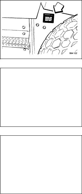
Serial No. (Fig. 1 and 2)
...........................................................................................................
Engine type (Fig. 3)
...........................................................................................................
Engine No. (Fig. 3)
Note: Fill in the above listed data when receiving the machine.
Upon receipt of the machine our organization will instruct you about correct operation and maintenance.
Please observe strictly all safety regulations and notes on potential dangers!
Fig. 1
Fig. 2
Fig. 3
|
Table of Contents |
Technical Data |
Section 1 |
Safety Regulations |
Section 2 |
Indicators and Controls |
Section 3 |
Operation |
Section 4 |
Maintenance |
Section 5 |
Trouble Shooting |
Section 6 |
Section 1
TECHNICAL DATA
TABLE OF CONTENTS
PAGE
Technical Data 2
4-2012 |
1-1 |

Section 1
TECHNICAL DATA
H2 |
|
|
|
|
H |
|
|
|
|
D |
|
|
|
|
S |
K |
|
|
|
|
A |
O1 |
W |
O2 |
|
L |
|
B |
|
Fig. 4
Dimensions |
A |
B |
D |
H |
H2 |
K |
L |
O1 |
O2 |
S |
W |
in mm (in) |
|
|
|
|
|
|
|
|
|
|
|
BW 177D-50 |
2500 |
1816 |
1228 |
2225 |
2860 |
375 |
4913 |
65 |
65 |
25 |
1686 |
|
(98.4) |
(71.5) |
(48.3) |
(87.6) |
(112.6) |
(14.7) |
(193.4) |
(2.6) |
(2.6) |
(1.0) |
(66.4) |
* |
|
BW 177 D-50 |
Weights |
|
|
Operating weight (CECE) with |
kg(lbs) |
6965 (15,355) |
ROPS |
|
|
with Cabin |
kg(lbs) |
7205 (15,880) |
Axle load, drum (CECE) with ROPS |
kg(lbs) |
4100 (9,040) |
Rear axle load (CECE) with ROPS |
kg(lbs) |
2865 (6,315) |
Static linear load with ROPS |
kg/cm (lbs/in) |
24.3 (136.1) |
Travel characteristics |
|
|
Travel speed (1) |
km/h(mph) |
0 ... 7 (0-4.3) |
Travel speed (2) |
km/h(mph) |
0 ... 11 (0-6.8) |
Max. gradability |
% |
45 |
(depending on soil) |
|
|
Engine |
|
|
Engine manufacturer |
|
Cummins |
Type |
|
B3.3T |
Cooling |
|
Water |
Number of cylinders |
|
4 |
Rated power DIN ISO 14396 |
kW (hp) |
55 (74) |
Rated speed |
1 rpm |
2600 |
Fuel |
|
Diesel |
1-2 |
4-2012 |
|
|
Section 1 |
|
|
TECHNICAL DATA |
* |
|
BW 177 D-50 |
Electrical equipment |
V |
12 |
Drive system |
|
hydrostatic |
Driven axles |
|
2 |
Brakes |
|
|
Service brake |
|
hydrostatic |
Parking brake |
|
hydr.-mech. |
Steering |
|
|
Type of steering |
|
articulated |
Steering operation |
|
hydrostatic |
Vibration |
|
|
Vibrating drum |
|
1 |
Drive system |
|
hydrostatic |
Frequency |
Hz (VPM) |
30/40 (1,800/2,400) |
Amplitude |
mm (in) |
1,8/0,9 (.071/.035) |
Tires |
|
|
Tire size |
|
14.9-24/6PR |
Tire tread |
|
Diamond (R3) |
Air pressure |
bar (psi) |
1,9 (27.6) |
Filling capacities |
|
|
Engine Oil** |
Litres (gal) |
8.5 (2.24) |
Fuel |
Litres (gal) |
150 (40) |
Hydraulic oil |
Litres (gal) |
60 (16) |
Coolant W/O Heating |
Litres (gal) |
23.5 (6.2) |
Coolant W/ Heating |
Litres (gal) |
25.5 (6.73) |
*The right for technical modifications remains reserved
**With filter
4-2012 |
1-3 |

Section 1
TECHNICAL DATA
H2 |
|
|
|
|
H |
|
|
|
|
D |
|
|
|
|
S |
K |
|
|
|
|
A |
O1 |
W |
O2 |
|
L |
|
B |
|
Fig. 4
Dimensions in |
A |
B |
D |
H |
H2 |
K |
L |
O1 |
O2 |
S |
W |
mm (in) |
|
|
|
|
|
|
|
|
|
|
|
BW 177DH-50 |
2500 |
1816 |
1228 |
2225 |
2860 |
375 |
4913 |
65 |
65 |
25 |
1686 |
|
(98.4) |
(71.5) |
(48.3) |
(87.6) |
(112.6) |
(14.7) |
(193.4) |
(2.6) |
(2.6) |
(1.0) |
(66.4) |
BW 211PDH-50 |
2500 |
1816 |
1228 |
2225 |
2860 |
375 |
4913 |
65 |
65 |
25 |
1686 |
|
(98.4) |
(71.5) |
(48.3) |
(87.6) |
(112.6) |
(14.7) |
(193.4) |
(2.6) |
(2.6) |
(1.0) |
(66.4) |
* |
|
BW 177DH-50 |
BW 211 PDH-50 |
Weights |
|
|
|
Operating weight (CECE) with |
kg(lbs) |
7095 (15,640) |
7310 (16,115) |
ROPS |
|
|
|
with Leveling Blade |
kg(lbs) |
N/A |
7910 (17,440) |
with Cabin |
kg(lbs) |
7340 (16,160) |
7550 (16,640) |
Axle load, drum (CECE) with ROPS |
kg(lbs) |
4115 (9,070) |
4330 (9,545) |
with Leveling Blade |
kg(lbs) |
N/A |
4835 (10,660) |
Rear axle load (CECE) with ROPS |
kg(lbs) |
2980 (6,570) |
2980 (6,570) |
Static linear load with ROPS |
kg/cm (lbs/in) |
24.4 (136.6) |
— |
Travel characteristics |
|
|
|
Travel speed (1) |
km/h(mph) |
0 ... 4.0 (2.5) |
0 ... 4.0 (2.5) |
Travel speed (2) |
km/h(mph) |
0 ... 6.5 (4.0) |
0 ... 6.5 (4.0) |
Travel speed (3) |
km/h(mph) |
0 ... 13.0 (8.0) |
0 ... 13.0 (8.0) |
Max. gradability |
% |
55 |
55 |
(depending on soil) |
|
|
|
Engine |
|
|
|
Engine manufacturer |
|
Cummins |
Cummins |
Type |
|
B3.3T |
B3.3T |
Cooling |
|
Water |
Water |
Number of cylinders |
|
4 |
4 |
Rated power DIN ISO 14396 |
kW (hp) |
55 (74) |
55 (74) |
Rated speed |
1 rpm |
2600 |
2600 |
Fuel |
|
Diesel |
Diesel |
1-4 |
4-2012 |
Section 1
TECHNICAL DATA
* |
|
BW 177 DH-50 |
BW 177 PDH-50 |
Electrical equipment |
V |
12 |
12) |
Drive system |
|
hydrostatic |
hydrostatic |
Driven axles |
|
2 |
2 |
Brakes |
|
|
|
Service brake |
|
hydrostatic |
hydrostatic |
Parking brake |
|
hydr.-mech. |
hydr.-mech. |
Steering |
|
|
|
Type of steering |
|
articulated |
articulated |
Steering operation |
|
hydrostatic |
hydrostatic |
Vibration |
|
|
|
Vibrating drum |
|
1 |
1 |
Drive system |
|
hydrostatic |
hydrostatic |
Frequency |
Hz (VPM) |
30/40 (1,800/2,400) |
30/40 (1,800/2,400) |
Amplitude |
mm (in) |
1,8/0,9 (.071/.035) |
1,70/0,9 (.064/.035) |
Tires |
|
|
|
Tire size |
|
14.9-24/6PR |
14.9-24/6PR |
|
|
Diamond (R3) |
Tractor (R1) |
Air pressure |
bar (psi) |
1,9 (27.6) |
1,6 (23.2) |
Filling capacities |
|
|
|
Engine Oil ** |
Litres (gal) |
8.5 (2.24) |
8.5 (2.24) |
Fuel |
Litres (gal) |
150 (40) |
150 (40) |
Hydraulic oil |
Litres (gal) |
60 (16) |
60 (16) |
Coolant W/O Heating |
Litres (gal) |
23.5 (6.2) |
23.5 (6.2) |
Coolant W/ Heating |
Litres (gal) |
25.5 (6.73) |
25.5 (6.73) |
*The right for technical modifications remains reserved
**With filter
4-2012 |
1-5 |
Section 1
TECHNICAL DATA
NOTES
1-6 |
4-2012 |
Section 2
SAFTEY REGULATIONS
TABLE OF CONTENTS
PAGE General 3 Loading the machine 4 Towing the machine 4 Starting the machine 4
Before starting 4 Starting 5 Starting with jump leads 5 Starting in closed rooms 5 Driving the machine 5 Driving on slopes and gradients 6 Check the effect of vibration 6 Parking the machine 6 Parking on slopes and gradients 6 Filling the fuel tank 6 Fire protection measures 6 Maintenance work 6 Working on hydraulic lines 7 Changing hydraulic hoses 7 Working on the engine 7 Working on electrical equipment 7 Working on the battery 7 Working on the fuel system 8
4-2012 |
2-1 |
Section 2
SAFTEY REGULATIONS
Working on wheels and tires 8 Cleaning 8 After maintenance work 8 Repair 8 Test 8
2-2 |
4-2012 |

General
This BOMAG machine is built in accordance with thelatesttechnicalstandardandthevalidtechnical rules and regulations. There is, however, a risk of danger for persons and property if:
•• the machine is used for purposes other than those it is intended for
•• the machine is operated by untrained personnel
•• the machine is modified or converted in an unprofessional way
•• the applicable safety regulations are not observed.
Eachpersoninvolvedinoperation,maintenanceand repairofthemachinemustthereforereadandapply these safety regulations. This should be confirmed by obtaining the signatures of the customer, if necessary.
Furthermorethefollowingregulationsandinstructions are obviously also valid:
•• applicable accident prevention instructions
•• generally acknowledged safety and road traffic regulations
•• country specific safety regulations. It is the duty of the operator to know and observe these regulations. This applies also for local regulations and the regulations for various types of manual work. If the recommendations in this manual differ from the regulations valid in your country, you must strictly observe the regulations in your country.
Intended use
This machine must only be used for:
•• compaction of bituminous materials, e.g. road surface layers. (AC and AD machines only)
•• medium and heavy compaction tasks in earth work (road sub-bases)
•• This machine must only be operated with fully functional safety equipment.
•• The machine should be checked by an expert once every year.
Section 2
SAFTEY REGULATIONS
Unintended use
Dangers may, however, arise from the machine if it is used by untrained personnel in an unprofessional way or if it is used for purposes other than those mentioned in these instructions.
Do not work with vibration on hard concrete, on a cured concrete layer or heavily frozen ground.
Starting and operation of the machine in an explosive environment is prohibited.
Who is allowed to work with the machine?
The machine must only be operated by trained and authorized persons which are at least 18 years of age. The responsibilities for the operation of the machine must be clearly specified and complied with.
Persons under the influence of alcohol, medication or drugs must not operate, service or repair the machine.
Maintenanceandrepairtasksrequirespecificknowledge and must therefore only be carried out by trained and qualified personnel.
Conversions and alterations to the machine
Unauthorizedconversionstothemachineareprohibited for safety reasons.
Original parts and accessories have been specially designed for this machine. We wish to make expressly clear that we have not tested or authorized any original parts or special equipment not supplied by us. The installation and/or use of such products can impair the active and/or passive driving safety. The manufacturer expressly excludes any liability for damage resulting from the use of non-original parts or accessories.
Safety notes in the operating and maintenance instructions:
Sections marked like this point out possible dangers for persons.
4-2012 |
2-3 |

Section 2
SAFTEY REGULATIONS
Sections marked like this point out possible dangers for the machine or for parts of the machine.
Note: Sections marked like this provide technical information concerning the optimal economical use of the machine.
Environment Sections marked like this highlight activities for the safe
and environmental disposal of fuels and lubricants as well as replaced parts.
Observe all environment protection regulations.
Information and safety stickers/decals on the machine
Keep stickers/decals complete (see spare parts catalogue) and fully legible and observe their meaning.
Replace damaged or illegible stickers/decals immediately.
Loading the machine
Use only strong and stable loading ramps. The ramp inclination must be lower than the gradability of the machine.
Secure the machine against turning over or slipping off.
Secure the machine on the transport vehicle against rolling off, slipping and turning over.
Persons are highly endangered if:
•• they step or stand under loads being lifted
•• they remain in the drive range of the machine during a demonstration or during loading.
The machine must not swing about when lifted off the ground.
Use only safe lifting gear of sufficient load bearing capacity.
Attachtheliftinggearonlytothespecifiedliftingpoints.
Towing the machine
Since the machine is notfitted with a towing hitch, the machine cannot be towed with a tow bar.
Ifthemachinehastobetowedurgentlyoutofthedanger zone because of other risks, this must only be done on level ground or uphill using chains and ropes. For this purposetowingropesofsufficienttensilestrengthmust be fastened on the lifting eyes.
Afterreleasingthebrakethemachinecanonlybebraked by the towing vehicle.
Before releasing the brake block the machine with chocks to prevent unintended rolling.
Checking the Roll Over Protection Structure (ROPS)
The machine frame must not be distorted, bent or cracked in the area of the ROPS structure.
The ROPS structure must not show any rust, damage, hairline cracks or open fractures.
The ROPS must not rattle about when driving the machine. This would mean that the fastening screws are insufficiently fastened. All screwed connections must be tight and in accordance with the specifications (observethetighteningtorques).Screwsandnutsmust not be damaged, distorted or deformed.
No additional parts must be welded or bolted on and no holes must be drilled without the permission of the dealer,sincethismayimpairthestrengthofthestructure.
Starting the machine
Before starting
Operationofthemachineisonlypermittedwhensitting in the operator’s seat.
Use only machines which have been properly serviced at regular intervals.
Become acquainted with the equipment, the control elements, the working mode of the machine and the area you will be working in.
Use your personal protective outfit (hard hat, safety boots etc.).
Check before mounting the machine if:
•• there are persons or obstructions beside or under the machine
2-4 |
4-2012 |
•• the machine is free of any oily and combustible material
•• all handrails, steps and platforms are free of grease, oils, fuels, dirt, snow and ice
•• the engine compartment hood is closed and locked
To climb onto the machine use steps and handrails.
Check before starting, whether:
•• the machine shows any obvious defects
•• all protective devices are properly secured in their place
•• steering, brakes, control elements, lighting and warning horn are in order
•• the seat is correctly adjusted
•• the mirrors (if available) are clean and correctly adjusted.
Do not start the machine if any gauges, control lights or controls are defective.
Do not take any loose objects with you or fasten them to the machine.
On machines with ROPS you should always wear your seat belt!
Starting
Start and operate the machine only from the operator’s seat
For starting set all control levers to “neutral position”.
Do not use any starting aids such as Start Pilot or ether.
After starting check all gauges.
Starting with jump leads
Connect plus with plus and minus with minus (ground cable) - always connect the ground cable last and disconnect it first! Wrong connections may cause severe damage in the electric system.
Never start the engine by bridging the electrical connectionsonthestarter,becausethemachinewould probably start to move immediately.
Starting in closed rooms
Exhaust gases are toxic! Always ensure an adequate supply of fresh air when starting in closed rooms!
Section 2
SAFTEY REGULATIONS
Driving the machine
Persons in the endangered area
If the machine has turned over and the cabin door is jammed, use the right hand cabin window as an emergency exit.
Check if there are persons or obstacles in the danger area before starting or resuming work, especially when driving in reverse.
If necessary give warning signals. Stop work immediately if persons remain in the danger area despite the warning.
Do not step or stand into the articulation area of the machine while the engine is running. Danger of injury!
Driving
In events of emergency actuate the emergency stop switch immediately. Do not use the emergency stop push button as service brake.
Restart the machine only after the danger, that has caused the actuation of the emergency stop, has been eliminated.
If the machine has come in contact with high-voltage power lines:
•• do not leave the operator’s stand
•• warn others from coming too close to the machine or touching it
•• if possible drive the machine out of the danger zone
•• have the power shut off.
Operate the machine only from the operator’s seat.
Keep the cabin doors closed.
Do not adjust the operator’s seat while driving.
Do not climb onto or off the machine while driving.
Change the travel direction only while the machine is standing.
Do not use the machine to transport persons.
Stop the machine if you notice unusual noises or the development of smoke. Investigate the cause and have the fault corrected.
Always keep a safe distance to excavations and embankmentsandavoidallactivitieswhichcouldimpair the stability of the machine.
4-2012 |
2-5 |
Section 2
SAFTEY REGULATIONS
Do not work with vibration on hard concrete, on a cured concrete layer or heavily frozen ground.
When passing under flyovers, bridges, tunnels, electric power lines etc. keep a sufficient distance.
Driving on slopes and gradients
Do not drive up and down gradients, which exceed the maximum gradability of the machine.
Always drive extremely carefully on slopes and always directlyupordowntheslope,neverdiagonally.Change to the lower speed range before approaching the inclination.
Wet and loose soils reduce the ground adhesion of the machine and inclinations and slopes considerably. Higher risk of accident!
Behaviour in traffic
Match the speed of the machine to the working conditions.
Always allow loaded transport vehicles to pass.
Switch the lights on when the visibility is poor.
Keep clear of edges and embankments.
Check the effect of vibration
Whencompactingwithvibrationchecktheeffectofthe vibration on nearby buildings and underground supply lines (gas, water, sewage, electric power supply), stop vibratory compaction if necessary.
Never use the vibration on hard (frozen, concrete) ground. Risk of bearing damage!
Parking the machine
Park the machine on level and firm ground.
Before leaving the machine:
•• straighten the articulated joint to allow easy access to and from the machine.
•• return the travel lever to neutral position
•• apply the parking brake
•• shut the engine down and pull the ignition key out.
•• lock the cabin door
•• secure the machine against unauthorized use.
Do not jump off the machine, use access steps and hand rails.
Always secure parked machines, which could be in the way, with appropriate measures.
Parking on slopes and gradients
Secure the machine against rolling, place metal chocks in front of and behind the drums.
Filling the fuel tank
Do not inhale fuel fumes.
Refuel only after shutting the engine and the auxiliary heater down.
Do not refuel in closed rooms.
No open fire, do not smoke.
Do not spill any fuel. Catch running out fuel, do not let it seep into the ground.
Wipe off spilled fuel. Keep fuel free of dirt and water.
Leaking fuel tanks can cause explosions. Ensure tight fit of the fuel tank filling cover, replace it if necessary.
Fire protection measures
Make yourself acquainted with the location and the operation of fire extinguishers. Observe fire warning and fire fighting installations.
Maintenance work
Strictlyapplythespecifiedmaintenancetasks,including the changing of parts.
For service and repair work in the engine compartment support the engine compartment hood
Maintenanceworkmustonlybecarriedoutbyqualified and authorized personnel.
In case of maintenance and assembly work over-head make sure to use the prescribed or other safe access steps, ladders and gangways. Do not use parts of the machine as access steps. Keep unauthorized persons away from the machine.
Keep unauthorized persons away from the machine.
Do not perform maintenance work with the machine driving or the engine running.
Parkthemachineonhorizontal,levelandstableground.
Pull the key out of the ignition switch.
Lock the articulated joint with the articulation lock.
2-6 |
4-2012 |
Working on hydraulic lines
Always relieve the pressure in the hydraulic circuit beforeworkingonhydrauliclines.Hydraulicoilescaping under pressure may penetrate through the skin and causesevereinjury.Incaseofbeinginjuredbyhydraulic oil you should immediately seek medical advice, as otherwise this may lead to serious infections.
When adjusting the hydraulic system do not stand behind or in front of the drum/wheels.
Do not change the setting of high pressure relief valves.
Drain hydraulic oil at operating temperature - danger of scalding!
Catch running out hydraulic oil and dispose of environmentally.
Always catch and dispose of biological hydraulic oils separately.
Do not start the engine after draining off the hydraulic oil.
Once all work is completed (with the system depressurized!) check all connections and fittings for tight and leak-free fit.
Changing hydraulic hoses
Allhydraulichosesmustbeinspectedvisuallyatregular intervals.
Hydraulic hoses must be changed immediately if:
•• damage to the outer surface down to the lining (e.g. chafings, cuts, cracks)
•• embrittlement of the outer layer (development of cracks in the hose material)
•• deformation under pressurized and depressurized condition, which are not in accordance with the normal shape of the hydraulic hose
•• deformation in bends, e.g, squeezes, kinks, layer separation, formation of blisters
•• leakages.
•• non-observance of the installation requirements
•• separation of the hydraulic hose from the fitting
•• corrosion of the fitting, which impairs the function and the strength.
Section 2
SAFTEY REGULATIONS
•• Do not mix up hoses by mistake.
•• damage or deformation of the fitting, which impairs the function and strength of the hose/ hose connection.
Only genuine BOMAG hydraulic hoses ensure that the correct type of hose (pressure range) is used at the right place.
Working on the engine
Shut the engine down before opening the engine compartment hood.
Drain the engine oil at operating temperature - danger of scalding!
Wipe off spilled oil, catch running out oil and dispose of environmentally.
Store used filters and other oily materials in a separate, specially marked container and dispose of environmentally.
Do not leave any tools or other objects, which could cause damage, in the engine compartment.
Idle speed and full load speed must not be changed, since this would have a negative effect on the exhaust gas values and cause damage to engine and drive.
Turbo chargers work with high speeds and high temperatures. Keep hands, tools and materials away fromtheintakeandoutletopeningsoftheturbocharger and do not touch any hot surfaces. Check and replace the coolant only when the engine is cold.
Catch running out coolant and dispose of environmentally.
Working on electrical equipment
Before working on electrical equipment disconnect the battery and cover it with insulating material.
Do not use any fuses with higher ampere ratings or repair a fuse with a piece of wire. Fire hazard!
Always disconnect the battery before starting to weld on the machine.
Working on the battery
When working on the battery do not smoke, do not use open fire.
4-2012 |
2-7 |
Section 2
SAFTEY REGULATIONS
Do not let acid come in contact with skin and clothes. If being injured by acid flush off with clear water and seek for medical advice.
Metal objects (e.g. tools, rings, wrist watches) must not contact the battery poles - danger of short circuit and burns!
When recharging maintenance free batteries remove the plugs to avoid the accumulation of explosive gases.
When using an external battery to start the machine follow the respective instructions.
Dispose of old batteries environmentally.
Switch the charging current off before removing the charge clamps.
Ensure good ventilation, especially when charging the battery in a closed room.
Working on the fuel system
Do not inhale fuel fumes.
No open fire, do not smoke, do not spill any fuel.
Catchrunningoutfuel,donotletitseepintotheground and dispose of environmentally.
Working on wheels and tires
Explosion like bursting of tires and parts of rims and tires can cause severe or even deadly injuries.
The assembly of tires must only be carried out by experienced personnel and with the correct equipment. If necessary have the tires assembled in a qualified workshop.
Ensure correct tire pressure and do not exceed the highest specified pressure.
Check wheels and tires every day for specified pressure, cuts, bulges, damaged wheel rims, missing wheel studs and nuts. Do not drive with damaged tires or wheels.
Anti-stick emulsions for tires must only be mixed using water and concentrated anti-stick agent according to the specifications of the manufacturer of the anti-stick agent. Observe the regulations for the protection of the environment.
Cleaning
Do not clean the machine while the engine is running.
Do not use gasoline or other combustible substances for cleaning purposes.
When using steam cleaning equipment do not subject electrical components and insulating materials to the direct water jet, but cover them beforehand.
•• Do not guide the water jet into the exhaust or into the air filter.
After maintenance work
Reinstall all protective devices after completing the maintenance work.
Repair
Attach a warning tag to the steering wheel if the machine is defective.
Repairs must only be performed by qualified persons who have been instructed for this purpose. Use our repair instructions.
Exhaust gases are highly dangerous! Always ensure an adequate supply of fresh air when starting in closed rooms!
Test
Dependingonthetypeofapplicationandtheoperating conditions vibratory equipment has to be examined by a specialist whenever required, but at least once every year.
2-8 |
4-2012 |
Section 3
INDICATORS AND CONTROLS
TABLE OF CONTENTS
PAGE General notes 4
Description of indicators and control elements 4
4-2012 |
3-1 |

Section 3
INDICATORS AND CONTROLS
Fig.
3-2 |
4-2012 |
Section 3
INDICATORS AND CONTROLS
1 |
Ignition switch |
11 |
Warring light “ASC” Anti-Spin-Control1 |
|
2 |
Instrument cluster |
12 |
Rotary switch for direction indicators left/right3 |
|
3 |
Vent for heating and ventilation, driver3 |
13 |
Rotary switch for hazard light system3 |
|
4 |
Vent for heating and ventilation, footwell3 |
14 |
Rotary switch for lighting (StVZO)3 |
|
5 |
Push button vibration |
15 |
Rotary switch for working lights3 |
|
6 |
Travel lever |
16 |
Steering wheel adjustment lever3 |
|
7 |
Rotary switch vibration, high/low frequency |
17 |
Rotary momentary contact switch for engine |
|
8 |
Rotary switch for speed limitation control |
|
speed and engine diagnotics inc/dec. |
|
1 |
BW177DH/PDH-50 |
|||
|
|
|||
9 |
Emergency stop push button |
2 |
Not Available |
|
|
|
3 |
Optional Equipment |
|
10 |
Push button for warning horn |
|
|
4-2012 |
3-3 |

Section 3
INDICATORS AND CONTROLS
General notes
Please read this section thoroughly before operating this machine if you are not yet conversant with the indicators and control elements. All functions are described in detail hereunder.
Paragraph 4 Operation contains only concise descriptions of the individual operating steps.
Description of indicators and control elements
Fig. 7 |
|
No. 1 = |
Ignition switch |
Position “P” |
= accessories on, ignition off, the |
|
key can be pulled out, engine |
|
not running. |
Position ”0” |
= ignition off, the key can |
|
be pulled out, engine not |
|
running. |
Position “I” |
= ignition on, all control and |
|
warning lights on the fault |
|
monitoring board light up for |
|
a moment. The lighting can be |
|
switched on. |
Position “II” |
= not used |
Position “III” |
= turn further against spring |
|
pressure, the engine starts. |
|
Allow the ignition key to return |
|
to the “I” position when the |
|
engine starts. |
NOTE: The engine can only be started when the travel lever is in braking position.
The ignition switch is provided with a lock against repetitive starting. To repeat the starting procedure you must first turn the ignition switch back to “0”- position.
Run the engine warm for a short while before starting to work. Do not let the engine run at idling speed for longer than 10 minutes.
Do not shut the engine down all of a sudden from full speed, but let it idle for a while for temperature equalization.
3-4 |
4-2012 |

Section 3
INDICATORS AND CONTROLS
Fig. 8
No. 2 = Instrument cluster
NOTE: With the ignition switch in position I all gauges and instruments are switched on for 3 seconds.
a red |
= flashes when the engine |
|
|
|
overheats, the warning buzzer |
|
|
sounds, the engine is shut |
|
|
down after 2 minutes. Switch |
|
|
off vibration, run engine |
|
|
with idle speed or shut down |
|
|
engine if necessary, clean |
|
|
engine oil cooler and radiator, |
|
|
if necessary repair engine. |
b red |
= flashes if engine oil pressure |
|
|
|
too low, engine is shut down |
|
|
after 10 seconds. Check engine |
|
|
oil level, repair the engine if |
|
|
necessary. |
c yellow |
= |
N/A |
d yellow |
= Charge control light, lights if |
|
|
|
battery is not being charged. |
|
|
Check V-belt, if necessary |
|
|
repair the generator. |
e yellow |
= lights if the hydraulic oil filter |
|
|
|
is contaminated, the engine |
|
|
is shut down after 2 minutes. |
|
|
Check hydraulic system, |
|
|
replace hydraulic oil filter. |
f yellow |
= |
N/A |
g red |
= Parkingbrake,withlevershifted |
|
|
|
to parking brake position, with |
|
|
driver’s seat unoccupied. |
h green |
= |
Direction indicator*, flashes |
|
|
when the direction indicator |
|
|
switch is actuated. |
i yellow |
= Water separator in fuel pre- |
|
cleaner. Lights when the water |
|
proportion in the fuel filter |
|
reaches the contacts. |
j red |
= N/A |
k yellow |
= Glow Plugs indicator lights |
|
when temperature is low |
|
(pre-heating for starting) |
l red |
= Hazard light*, flashes when the |
|
hazard light is activated. |
m |
= Operating hour meter, counts |
|
the operating hours while |
|
the engine is running. All |
|
maintenance work must be |
|
performed according to the |
|
indicated operating hours. |
n |
= Fuel tank filling level. |
No. 3 = |
Vents for air conditioning, heating |
|
and ventilation, driver* |
No. 4 = |
Vents for air conditioning, heating |
|
and ventilation, footwell* |
*Optional equipment
4-2012 |
3-5 |

Section 3
INDICATORS AND CONTROLS
Fig. 9
No. 5 = Push button for vibration
•• Select or actuate the frequencies with the vibration selector switch.
•• Switch the vibration on or off by pressing the push button.
Fig. 10 |
|
|
|
No. 6 = |
Travel lever |
||
Position |
|
= Braking position sevice brake |
|
“middle” |
|
|
|
Position |
|
= Parking brake, to start the |
|
“middle, right” |
|
engine |
|
Position “I” |
|
= |
Forward travel |
Position “II” |
|
= |
Backwards travel |
NOTE: If the engine speed drops under load when driving on steep gradients, take the travel lever slightly back towards neutral. This relieves the hydraulic system and reduces the load on the diesel engine.
Fig. 11 |
|
|
No. 7 = |
Rotary switch for vibration |
|
Position |
|
= Vibration off |
“middle” |
|
|
Position “Right” |
= low amplitude, high frequency |
|
Position “Left” |
= high amplitude, low frequency |
|
3-6 |
4-2012 |

Section 3
INDICATORS AND CONTROLS
Fig. 12
No. 8 = Rotary Switch for speed range selection BW177 D-50
Position “turtle” |
= |
Working speed |
Position “rabbit |
= |
Transport speed |
|
|
|
|
|
|
Fig. 13
No. 8 = Rotary Switch for speed range selection BW177 DH-50/PDH-50
Position “turtle” |
= Working speed range on level |
|
ground or on inclinations |
|
steeper than 15% |
Position “rabbit, |
= Working speed range on level |
low” |
ground and on inclinations, |
|
with high working speed |
Position “rabbit, |
= Transport range, e.g. to drive |
high” |
to the work location, vibration |
|
not possible |
Fig. 14
No. 9 = Emergency stop switch
The engine will be shut down and the brake will close.
Danger of accident!
Operate only in emergency situations duringoperation,donotuseasaservice brake.
The machine should only be started again after the danger,thatcausedtheactuationoftheemergency stop switch, has been removed.
operate |
= push the button completely |
|
down, it will automatically lock |
|
in end position. |
unlock |
= turn the button clockwise and |
|
release it. |
to drive |
= move the travel lever first to |
|
braking position, then start the |
|
engine and choose the travel |
|
direction. |
For safety reasons the travel system of the machine will only be enabled after the travel lever has been shifted back to braking position.
4-2012 |
3-7 |

Section 3
INDICATORS AND CONTROLS
Fig. 15
No. 10 = Push button for warning horn
Fig. 16
No. 11= Fault warning light “ASC” Anti-Spin- Control BW177 DH-50/PDH-50
NOTE: Further trouble shooting by means of flashing codes on the ASC-control board in the electric junction box.
Operation of the machine can be continued, but you should inform the after sales service of BOMAG.
Fig. 17
No. 14 = Rotary switch for light system (StVZO)*
Position “Left” |
= |
Light off |
|
Position |
= Sidelights on, with ignition |
||
“Middle” |
|
switch in position “I” or “P” |
|
Position “Right” |
= |
Travel light on, with ignition |
|
|
|
switch in position “I”. |
|
|
|
|
|
|
|
|
|
Fig. 18
No. 15 = Rotary switch for working lights *
Position “Left” |
= |
Light off |
Position “Right” |
= |
Working lights on, with |
|
|
ignition switch in position “I” |
* Optional equipment
3-8 |
4-2012 |
 Loading...