

Page 1

BVP 10/30
Operating Instruction
S/N 861 834 42 1001>
Go to Discount-Equipment.com to order your parts
Maintenance Instruction
Original Operating Instructions
Single direction vibratory plate
www.discount-equipment.com
© 05/2019008 204 25 EN
Page 2
count-Equipment.com is your online resource for quality parts & equipment.
Dis
Florida: 561-964-4949 Outside Florida TOLL FREE: 877-690-3101
Need parts?
Click on this link: http://www.discount-equipment.com/category/5443-parts/ and
choose one of the options to help get the right parts and equipment you are looking
for. Please have the machine model and serial number available in order to help us
get you the correct parts. If you don’t find the part on the website or on one of the
online manuals, please fill out the request form and one of our experienced staff
members will get back to you with a quote for the right part that your machine needs.
We sell worldwide for the brands: Genie, Terex, JLG, MultiQuip, Mikasa, Essick, Whiteman,
Mayco, Toro Stone, Diamond Products, Generac Magnum, Airman, Haulotte, Barreto,
Power Blanket, Nifty Lift, Atlas Copco, Chicago Pneumatic, Allmand, Miller Curber, Skyjack,
Lull, Skytrak, Tsurumi, Husquvarna Target, Stow, Wacker, Sakai, Mi-T-M, Sullair, Basic,
Dynapac, MBW, Weber, Bartell, Bennar Newman, Haulotte, Ditch Runner, Menegotti,
Morrison, Contec, Buddy, Crown, Edco, Wyco, Bomag, Laymor, EZ Trench, Bil-Jax, F.S.
Curtis, Gehl Pavers, Heli, Honda, ICS/PowerGrit, IHI, Partner, Imer, Clipper, MMD, Koshin,
Rice, CH&E, General Equipment ,Amida, Coleman, NAC, Gradall, Square Shooter, Kent,
Stanley, Tamco, Toku, Hatz, Kohler, Robin, Wisconsin, Northrock, Oztec, Toker TK, Rol-Air,
APT, Wylie, Ingersoll Rand / Doosan, Innovatech, Con X, Ammann, Mecalac, Makinex, Smith
Surface Prep,Small Line, Wanco, Yanmar
Page 3
WARNING: Breathing diesel engine exhaust exposes you to chemicals
Go to Discount-Equipment.com to order your parts
known to the State of California to cause cancer and birth defects or other
reproductive harm.
Always start and operate the engine in a well-ventilated area.
If in an enclosed area, vent the exhaust to the outside.
Do not modify or tamper with the exhaust system.
Do not idle the engine except as necessary.
For more information go to www.P65warnings.ca.gov/diesel.
WARNING: Crude oil, gasoline, diesel fuel and other petroleum
products can expose you to chemicals including toluene and benzene,
which are known to the State of California to cause cancer and birth
defects or other reproductive harm.
These exposures can occur in and around oil fields, refineries, chemical
plants, transport and storage operations such as pipelines, marine
terminals, tank trucks and other facilities and equipment.
For more information go to www.P65Warnings.ca.gov/petroleum.
2
Page 4

Table of contents
Go to Discount-Equipment.com to order your parts
Table of contents
Introduction........................................................................................................................................... 7
1
1.1 Foreword........................................................................................................................................ 8
1.2 Machine type plate and engine type plate................................................................................ 10
2 Technical data...................................................................................................................................... 1
2.1 Noise and vibration data............................................................................................................ 14
2.1.1 Noise data.................................................................................................................................. 14
2.1.2 Vibration data............................................................................................................................. 14
3 Concerning your safety...................................................................................................................... 15
3.1 Basic prerequisites..................................................................................................................... 16
3.1.1 General...................................................................................................................................... 16
3.1.2 Explanation of signal words used:.............................................................................................. 16
3.1.3 Personal protective equipment................................................................................................... 17
3.1.4 Intended use.............................................................................................................................. 18
3.1.5 Improper use.............................................................................................................................. 18
3.2 Definition of responsible persons............................................................................................. 20
3.2.1 Operating company.................................................................................................................... 20
3.2.2 Expert / qualified person............................................................................................................ 20
3.2.3 Driver / operator......................................................................................................................... 20
3.3 Basic safety regulations for safe operation............................................................................. 22
3.3.1 Remaining dangers, remaining risks.......................................................................................... 22
3.3.2 Regular safety inspections......................................................................................................... 22
3.3.3 Modifications and alterations to the machine............................................................................. 22
3.3.4 Damage, defects, misuse of safety devices............................................................................... 22
3.3.5 Notes on operating the machine safely...................................................................................... 23
3.4 Handling fuels and lubricants.................................................................................................... 25
3.4.1 Preliminary remarks................................................................................................................... 25
3.4.2 Safety regulations and environmental protection regulations for handling gasoline.................. 26
3.4.3 Safety regulations and environmental protection regulations for handling fuel stabiliser........... 27
3.4.4 Safety regulations and environmental protection regulations for handling oil............................ 28
3.5 Loading / transporting the machine.......................................................................................... 29
3.6 Start-up procedure...................................................................................................................... 30
3.6.1 Prior to starting up...................................................................................................................... 30
3.6.2 Starting the engine..................................................................................................................... 30
3.7 Operation..................................................................................................................................... 31
3.7.1 Persons in the danger zone....................................................................................................... 31
3.7.2 Operation................................................................................................................................... 31
3.7.3 Parking the machine.................................................................................................................. 31
3.8 Refuelling..................................................................................................................................... 33
3.9 Maintenance work....................................................................................................................... 34
3.9.1 Preliminary remarks................................................................................................................... 34
3.9.2 Working on the engine............................................................................................................... 34
3.9.3 Cleaning work............................................................................................................................ 34
3.9.4 After maintenance work............................................................................................................. 34
3.10 Repair......................................................................................................................................... 35
1
3
BVP 10/30
Page 5

Table of contents
Go to Discount-Equipment.com to order your parts
3.11 Signage...................................................................................................................................... 36
3.12 Safety Components.................................................................................................................. 40
4 Machine description........................................................................................................................... 41
4.1 Function and design................................................................................................................... 42
4.2 Indicators and control elements................................................................................................ 45
4.2.1 Starter switch............................................................................................................................. 45
4.2.2 Recoil starter.............................................................................................................................. 46
4.2.3 Throttle lever.............................................................................................................................. 46
4.2.4 Fuel valve................................................................................................................................... 46
4.2.5 Choke lever................................................................................................................................ 47
5 Checks prior to start up...................................................................................................................... 49
5.1 Notes on safety........................................................................................................................... 50
5.2 Visual inspections and function tests....................................................................................... 51
5.3 Checking the engine oil level..................................................................................................... 53
5.4 Checking the fuel level, topping up fuel................................................................................... 54
6 Operation............................................................................................................................................. 55
6.1 Initial start-up.............................................................................................................................. 56
6.2 Guide handle............................................................................................................................... 57
6.2.1 Mounting the guide handle......................................................................................................... 58
6.2.2 Removing the guide handle....................................................................................................... 60
6.3 Plastic mat................................................................................................................................... 62
6.3.1 Mount the plastic mat................................................................................................................. 63
6.3.2 Removing the plastic mat........................................................................................................... 65
6.4 Starting the engine...................................................................................................................... 67
6.5 Operation..................................................................................................................................... 71
6.6 Parking the machine in secured condition............................................................................... 74
7 Loading / transporting the machine.................................................................................................. 77
7.1 Preliminary remarks and safety notes...................................................................................... 78
7.2 Loading with lifting tackle.......................................................................................................... 79
7.3 Loading without lifting tackle.................................................................................................... 80
7.4 Lashing the machine to the transport vehicle.......................................................................... 81
7.5 After transport............................................................................................................................. 83
8 Maintenance........................................................................................................................................ 85
8.1 Preliminary remarks and safety notes...................................................................................... 86
8.2 Fuels and lubricants................................................................................................................... 87
8.2.1 Engine oil................................................................................................................................... 87
8.2.2 Fuel............................................................................................................................................ 87
8.3 List of fuels and lubricants........................................................................................................ 89
8.4 Maintenance Table...................................................................................................................... 90
8.5 Running-in instructions.............................................................................................................. 91
8.5.1 General...................................................................................................................................... 91
8.5.2 After 25 operating hours............................................................................................................. 91
8.6 Monthly........................................................................................................................................ 92
8.6.1 Air filter maintenance................................................................................................................. 92
8.7 Semi-annually.............................................................................................................................. 93
4
BVP 10/30
Page 6

Table of contents
Go to Discount-Equipment.com to order your parts
8.7.1 Changing the engine oil............................................................................................................. 93
8.8 Annually....................................................................................................................................... 94
8.8.1 Checking, adjusting the valve clearance.................................................................................... 94
8.8.2 Replacing the spark plug............................................................................................................ 98
8.8.3 Replacing the fuel strainer......................................................................................................... 99
8.8.4 Replacing the starter rope........................................................................................................ 100
8.8.5 Replacing the air filter.............................................................................................................. 102
8.8.6 Replacing the V-belt................................................................................................................. 103
8.9 As required................................................................................................................................ 106
8.9.1 Cleaning the cooling fins and the cooling air intake openings................................................. 106
8.9.2 Cleaning the machine.............................................................................................................. 107
8.9.3 Cleaning, checking the spark plug, replacing if necessary...................................................... 108
8.9.4 Checking, adjusting the engine speed..................................................................................... 110
8.9.5 Measures for longer shut-down periods................................................................................... 112
9 Troubleshooting................................................................................................................................ 115
9.1 Preliminary remarks.................................................................................................................. 116
9.2 Engine malfunctions................................................................................................................. 117
9.3 What to do if the engine has flooded...................................................................................... 118
10 Disposal............................................................................................................................................. 123
10.1 Final shut-down of machine................................................................................................... 124
11 List of special tools........................................................................................................................... 125
12 Terminology....................................................................................................................................... 127
5
BVP 10/30
Page 7

1 Introduction
Go to Discount-Equipment.com to order your parts
Introduction
7
BVP 10/30
Page 8

Introduction – Foreword
Go to Discount-Equipment.com to order your parts
1.1 Foreword
BOMAG manufactures machines for earth, asphalt and refuse
compaction, stabilizers/recyclers as well as planers and
pavers.
BOMAG’
production and testing methods, such as lifetime tests of all
important components and highest quality demands guarantee maximum reliability of your machine.
These operating and maintenance instructions are part of your
machine.
They provide necessary information to operate your machine
safely and properly.
They also contain information on required operating, maintenance
and repair measures.
Carefully read the operating and maintenance instructions before
taking your machine into operation.
Please observe the safety regulations strictly and follow all instructions to ensure safe operation.
If you are not yet acquainted with the controls and indicating elements on this machine, you should thoroughly read the corresponding chapter
on page 45.
The description of the individual operating steps including the
notes on safety to be followed can be found in chapter “Operation”
Ä
Chapter 6 ‘Operation’ on page 55.
Before every start up, carry out all required visual inspections and
function tests
Ensure the compliance with the specified operating, maintenance
and repair measures to maintain the functional safety of your
machine.
A description of all necessary maintenance work, maintenance
intervals as well as information on fuels and lubricants can be
found in the chapter “Maintenance”
on page 85.
Do not service or repair your machine by yourself to avoid harming
persons or damaging material or environment.
The machine must only be serviced and repaired by qualified and
authorized personnel.
Contact our Customer Service to carry out the required maintenance work or necessary repairs.
In case of operating errors, inadequate maintenance or the use of
unapproved fuels and lubricants all warranty claims will become
null and void.
s vast experience in connection with state-of-the-art
Ä
Chapter 4.2 ‘Indicators and control elements’
Ä
Chapter 5 ‘Checks prior to start up’ on page 49.
Ä
Chapter 8 ‘Maintenance’
For your own personal safety you should only use original parts
from BOMAG.
For your machine we offer service kits to make maintenance
easier.
8
BVP 10/30
Page 9

Introduction – Foreword
Go to Discount-Equipment.com to order your parts
In the course of technical development we reserve the right for
technical modifications without prior notification.
These operating and maintenance instructions are also available in
other languages.
Apart from that, you can also order the spare parts catalogue
against the serial number of your machine.
The above notes do not constitute an extension of the warranty
and liability conditions specified in the general sales and delivery
conditions of BOMAG GmbH.
We wish you successful work with your BOMAG machine.
9
BVP 10/30
Page 10
Made by
Designation Type
Nominal Power Operating Mass Year of Construction
Serial-No.
Patent Protection
56154 Boppard;GERMANY Made in Germany
1
2
B-DEC-0270
Introduction – Machine type plate and engine type plate
Go to Discount-Equipment.com to order your parts
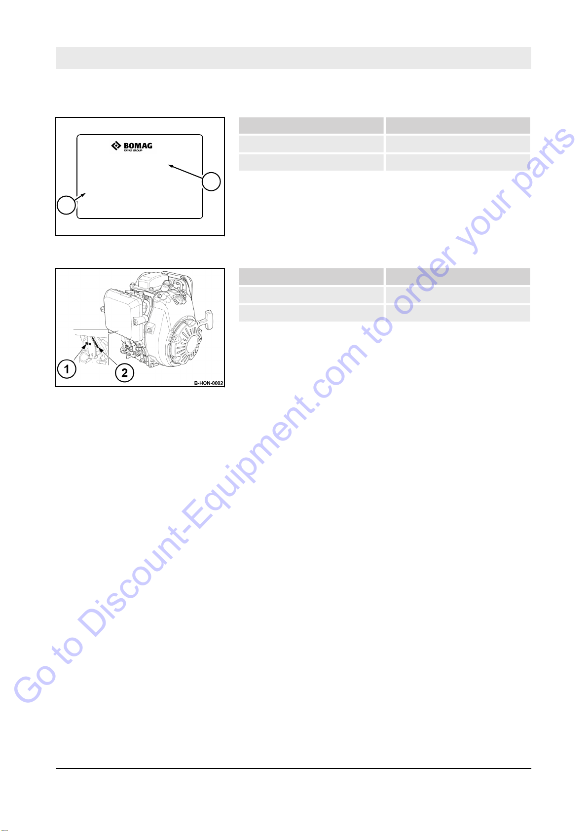
1.2 Machine type plate and engine type plate
Please enter here:
Machine type (1):
Serial number (2):
Fig. 1: Machine type plate (example)
Please enter here:
Engine type (1):
Engine number (2):
Fig. 2: Engine type and engine
number
10
BVP 10/30
Page 11

2 Technical data
Go to Discount-Equipment.com to order your parts
Technical data
11
BVP 10/30
Page 12
Technical data
Go to Discount-Equipment.com to order your parts
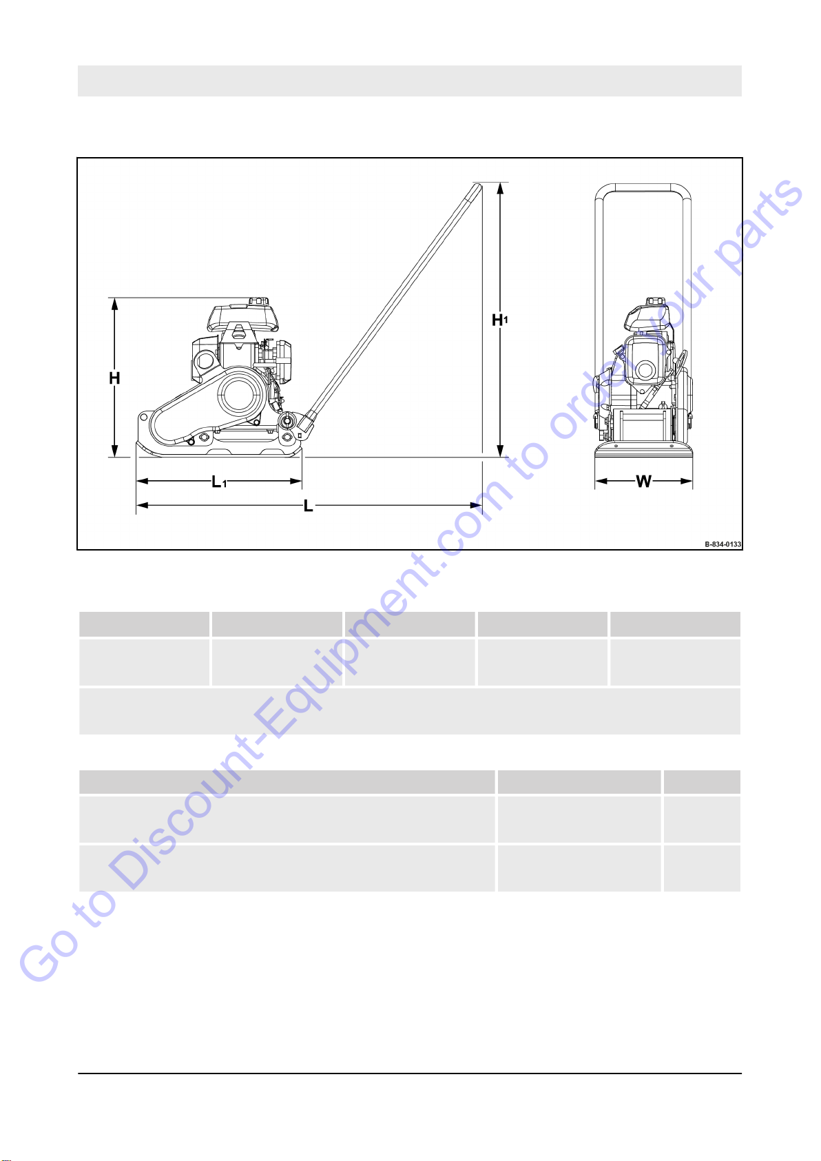
Dimensions
Fig. 3
H H
489
(19.3)
Dimensions in millimetres
(Dimensions in inch)
Weights
Operating weight (CECE) 47
Basic weight 46
1
840
(33.1)
L L
1058
(41.7)
1
509
(20.0)
W
300
(11.8)
(104)
(101)
(lbs)
(lbs)
kg
kg
12
BVP 10/30
Page 13

Technical data
Go to Discount-Equipment.com to order your parts
Travel characteristics
Max. working speed 25
(82)
Max. gradability (depending on soil) 30 %
Max. cross slope 36 %
Drive
Engine manufacturer Honda
Type GXR 120
Cooling system Air
Number of cylinders 1
Rated power SAE J 1349 2.1
(2.8)
Rated speed 3600
Drive system mechanical
Exciter system
m/min
(ft/min)
kW
(hp)
min
-1
Frequency 100
(6000)
Centrifugal force 10
(2248)
Amplitude 1.34
(0.053)
Filling capacities
Fuel (gasoline) 0.8
(0.2)
Hz
(vpm)
kN
(lbf)
mm
(in)
(gal us)
l
13
BVP 10/30
Page 14

Technical data – Noise and vibration data
Go to Discount-Equipment.com to order your parts
2.1 Noise and vibration data
The following noise and vibration data were determined in accordance with the following guidelines under equipment specific conditions and by using harmonized standards:
n EU Machine Directive edition 2006/42/EU
n Noise Emission Directive 2000/14/EU, Noise Protection Direc-
tive 2003/10/EU
ibration Protection Directive 2002/44/EU
n V
During operation these values may vary because of the prevailing
operating conditions.
2.1.1
Sound pressure level at the operator's stand
Guaranteed sound power level
Noise data
2.1.2 Vibration data
Hand-arm vibration
LpA = 91 dB(A), determined acc. to ISO 11201 and EN 500.
WARNING!
Loss of hearing caused by too high noise bur-
dens!
– Wear your personal protective equipment (ear
protection).
= 101 dB(A), determined acc. to ISO 3744 and EN 500
L
A
W
Vector total of the weighted effective acceleration in three orthogonal directions:
Total vibration value ahv = 3.7 m/s2 on crushed rock determined
acc. to ISO 5349 and EN 500.
Associated uncertainty K = 0.3 m/s2, determined acc. to EN
12096.
Observe the daily vibration load (work safety acc. to 2002/44/EC).
Hand-arm vibration with comfort
guide handle (optional equipment)
Vector total of the weighted effective acceleration in three orthogonal directions:
Total vibration value ahv £ 2.5 m/s2 on crushed rock determined
acc. to ISO 5349 and EN 500.
Associated uncertainty K = 0.2 m/s2, determined acc. to EN
12096.
Observe the daily vibration load (work safety acc. to 2002/44/EC).
14
BVP 10/30
Page 15

Concerning your safety
Go to Discount-Equipment.com to order your parts
3 Concerning your safety
15
BVP 10/30
Page 16

Concerning your safety – Basic prerequisites
Go to Discount-Equipment.com to order your parts
3.1 Basic prerequisites
3.1.1
General
This machine has been built in compliance with the latest technical
standard and complies with the applicable regulations and technical rules.
However, dangers for persons and property may arise from this
machine, if:
n it is used for purposes other than the ones it is intended for
n it is operated by untrained personnel,
n it is changed or converted in an unprofessional way,
n the safety instructions are not observed.
Each person involved in the operation, maintenance and repair of
the machine must therefore read and comply with these safety regulations. If necessary
vant signatures as confirmation.
Furthermore, the following obviously also applies:
n applicable accident prevention instructions,
n generally accepted safety and road traffic regulations,
n country/state specific safety regulations.
It is the duty of the operator to be acquainted with the safety regulations and to apply these accordingly
regulations and regulations concerning different types of handling
activities. Should the recommendations in these instructions be different from the regulations valid in your country, you must comply
with the safety regulations valid in your country.
, the operating company must obtain the rele-
. This also applies for local
,
3.1.2 Explanation of signal words used:
DANGER!
Danger to life if failing to comply!
Sections marked accordingly indicate an extremely
dangerous situation that could lead to fatal or
severe injuries, if this warning is disregarded.
WARNING!
Danger to life or danger of severe injuries if
failing to comply!
Sections marked accordingly indicate a dangerous
situation that could lead to fatal or severe injuries,
if this warning is disregarded.
16
BVP 10/30
Page 17

Concerning your safety – Basic prerequisites
Go to Discount-Equipment.com to order your parts
CAUTION!
Danger of injury if failing to comply!
Sections marked accordingly indicate a dangerous
situation that could lead to fatal or severe injuries,
if this warning is disregarded.
NOTICE!
Danger of material damage if failing to comply!
Sections marked accordingly indicate possible
dangers for machines or components.
Sections marked accordingly indicate technical
information or notes on using the machine or its
components.
ENVIRONMENT!
Environmental damage if failing to comply!
Paragraphs marked accordingly indicate practices
for safe and environment-friendly disposal of fuels
and lubricants as well as replacement parts.
3.1.3 Personal protective equipment
Depending on the work to be carried out, personal protective equipment is required (to be provided
by the operating company):
Working clothes Tight fitting working clothes with low tear resistance, tight
sleeves and without any projecting parts protect against
being caught by moving components.
Safety shoes To protect against heavy falling parts and slipping on
slippery ground.
Protective gloves To protect the hands against excoriation, punctures or
deep injuries, against irritating and caustic substances
as well as against burns.
17
BVP 10/30
Page 18

Concerning your safety – Basic prerequisites
Go to Discount-Equipment.com to order your parts
Safety goggles To protect the eyes against airborne particles and
squirting fluids.
Face protection To protect the face against airborne particles and
squirting fluids.
Hard hat To protect the head against falling parts and to protect
against injuries.
Hearing protection To protect hearing against excessive noise.
Respiratory protection To protect respiratory tracts against substances or parti-
3.1.4 Intended use
3.1.5
Improper use
cles.
This machine must only be used for:
n Compaction of all types of soils
n Repair work on all types of soil
n Paving of walkways
ork in trenches
n W
n Underfilling and compaction of hard shoulders
Intended use also includes compliance with the specified operating, maintenance and repair measures.
Dangers may arise from the machine when it is used for purposes
other than the one it is intended for.
Any danger caused by improper use is the sole responsibility of the
operating company or driver/operator, the manufacturer cannot be
made liable.
18
BVP 10/30
Page 19

Concerning your safety – Basic prerequisites
Go to Discount-Equipment.com to order your parts
Examples for improper use are:
n dragging the machine along as a measure of transportation
n throwing the machine off the transport vehicle
n attaching an additional weight to the machine
It is not permitted to stand on the machine while working.
Lifting tackle must be removed before starting work.
Starting and operating the machine in explosive environments and
in underground mining is prohibited.
The lifting and lashing points specified in these instructions must
be used. It is prohibited to use other lifting and lashing points (e.g.
guide handle, steering rod).
19
BVP 10/30
Page 20

Concerning your safety – Definition of responsible persons
Go to Discount-Equipment.com to order your parts
3.2 Definition of responsible persons
3.2.1
Operating company
3.2.2 Expert / qualified person
The operating company is the natural or juridical person who uses
the machine or in who's name the machine is used.
The operating company must make sure that the machine is only
used for the purpose it is intended for and in strict compliance with
the safety regulations mentioned in these operating and maintenance instructions.
The operating company must determine and assess the danger in
its company. It must then take appropriate action to ensure health
and safety at work for its employees and point out any remaining
dangers.
The operating company must determine whether there are special
operational hazards such as a toxic atmosphere or limiting soil
conditions. Such conditions require special, additional measures to
remove or reduce the hazard.
The operating company must make sure that all users read and
understand the information concerning safety.
The operating company is responsible for the planning and professional execution of regular safety inspections.
3.2.3 Driver / operator
An expert / qualified person is a person who, based on his/her professional education and experience, has profound knowledge in
the field of construction equipment and the machine in question in
particular.
This person is acquainted with the applicable governmental industrial safety regulations, accident prevention instructions, guidelines
and generally acknowledged technical rules and regulations
(standards, directives, technical rules of other member states of
the European Union or other contractual states concerning the
agreement about the European Economic Area) in as far as is necessary to be able to judge the safe condition of this machine.
This machine must only be operated by trained, instructed persons
entrusted by the operating company aged 18 or more.
Observe your local laws and regulations.
Rights, obligations and rules of conduct for driver or operator:
The driver or operator must:
n be instructed about his rights and obligations,
n wear protective equipment as appropriate for the application,
n have read and understood the operating instructions,
20
BVP 10/30
Page 21

Concerning your safety – Definition of responsible persons
Go to Discount-Equipment.com to order your parts
n have made himself familiar with the operation of the machine,
n be physically and psychologically able to drive and operate the
machine.
Persons under the influence of alcohol, medication or drugs are not
allowed to operate, service or repair the machine.
Maintenance and repair work requires specific knowledge and
must therefore only be performed by trained specialists.
21
BVP 10/30
Page 22

Concerning your safety – Basic safety regulations for safe operation
Go to Discount-Equipment.com to order your parts
3.3 Basic safety regulations for safe operation
3.3.1
Remaining dangers, remaining risks
3.3.2 Regular safety inspections
Despite careful work and compliance with standards and regulations it cannot be ruled out that further dangers may arise when
working with and handling the machine.
Both the machine as well as all other system components comply
with the currently valid safety regulations. Nevertheless, remaining
risks cannot be ruled out completely, even when using the machine
for the purpose it is intended for and following all information given
in the operating instructions.
A remaining risk can also not be excluded beyond the actual
danger zone of the machine. Persons remaining in this area must
pay particular attention to the machine, so that they can react
immediately in case of a possible malfunction, an incident or failure
etc.
All persons remaining in the area of the machine must be informed
about the dangers that arise from the operation of the machine.
Have the machine inspected by an expert / qualified person as
required for the conditions the machine is working under, but at
least once every year.
3.3.3 Modifications and alterations to the machine
Unauthorized changes to the machine are prohibited for safety reasons.
Original parts and accessories have been specially designed for
this machine.
We wish to make explicitly clear that we have not tested or
approved any parts or accessories not supplied by us.
The installation and/or use of such products may have an adverse
effect on the active and/or passive safety.
3.3.4 Damage, defects, misuse of safety devices
Machines which are not safe to operate or in traffic must be immediately taken out of service and shall not be used, until these deficiencies have been properly rectified.
Safety installations and switches must neither be removed nor
must they be made ineffective.
22
BVP 10/30
Page 23

Concerning your safety – Basic safety regulations for safe operation
Go to Discount-Equipment.com to order your parts
3.3.5 Notes on operating the machine safely
Exhaust fumes contain toxic substances and can damage your
health, cause unconsciousness or even death.
n Do not inhale exhaust gases.
n Avoid operation in closed or partly closed rooms, or ensure
adequate ventilation when working in trenches.
Hand-arm vibrations can cause health problems such as damage
to bones or joints, circulatory or neurological disorders.
n Observe the daily vibration load (work safety acc. to 2002/44/
EC).
n If required, observe applicable local laws and regulations.
ake sufficient breaks.
n T
Noise pollution can damage health and lead to loss of hearing.
n Always wear ear protection when operating.
Wearing wrong work clothing or being negligent regarding the personal protective equipment can result in serious injuries.
n Work clothing should be tight fitting but not impeding.
n Do not wear loose clothing (e.g. scarves, open jackets).
n Do not have long, loose hair.
n Do not wear jewellery (e.g. watches, chains, rings, etc.).
n Wear your personal protective equipment.
n Wear respiratory protection if working in a dusty environment.
n If required, observe applicable local laws and regulations.
Never operate a machine which is not safe in its function.
Never operate a machine without or with damaged safety elements.
Always work with suf
Children cannot assess dangers and behave unpredictably.
ficient lighting.
n Delimit the working area.
n Prevent unauthorized persons, especially children, from
accessing the machine as well as fuels and lubricants.
n Stop work immediately if a child approaches.
Obstacles or holes in the working area can cause slipping, stumbling or falling.
n Look out for obstacles or holes in the working area.
n If possible, remove obstacles before starting work.
A wrong working methods can result in serious injuries.
n Operate the machine only according to its intended use.
n Always work calmly and concentratedly
n Guide the machine only by the guide handle.
n Guide the machine so that your hands do not hit against solid
objects.
n Keep feet clear of the vibrating base plate.
n Ensure a firm stand and keep your balance. Special care must
be taken on uneven ground.
23
BVP 10/30
.
Page 24

Concerning your safety – Basic safety regulations for safe operation
Go to Discount-Equipment.com to order your parts
n The machine must not tip, roll of
operation.
n Observe the gradability and the maximum cross slope of the
Ä
machine
Check how the vibrations affect the working environment.
n The load bearing capacity of the soil can be reduced by the
vibration effect.
n The side walls of trenches, construction pits and slopes must
be stable and mustn’t crumble when exposed to vibration.
n When compacting with vibration, you must always check the
effect of the vibration on nearby buildings and underground
supply lines (gas, water, sewage, electric power).
n If necessary, stop compacting with vibration.
n If unsure, consult an expert / qualified person to assess the
working environment.
Components can be very hot during or immediately after operation
(e.g. engine, exhaust, exciter system).
n Do not touch hot components.
n Keep waste such as paper
hot components.
n Keep a fire extinguisher at hand.
Gasoline is explosive!
Chapter 2 ‘Technical data’ on page 11.
f, slide down or fall during
, dry leaves or dry grass away from
n Safety regulations and environmental protection regulations
must be followed when handling gasoline.
n Do not allow gasoline to come into contact with hot compo-
nents.
n Before filling up, turn of
engine cool down.
n Smoking and open fire is prohibited.
n Keep away from heat sources, sparks and other sources of
ignition.
n Do not spill any gasoline.
Danger to life caused by an operationally unsafe machine!
n The machine must only be serviced and repaired by qualified
and authorized personnel.
n Contact our customer service to carry out the required mainte-
nance work or necessary repairs.
f the engine and let the machine and
24
BVP 10/30
Page 25

Concerning your safety – Handling fuels and lubricants
Go to Discount-Equipment.com to order your parts
3.4 Handling fuels and lubricants
3.4.1
Preliminary remarks
The operating company must ensure that all professional users
have read and follow the corresponding safety data sheets for the
individual fuels and lubricants.
Safety data sheets provide valuable information about the following
characteristics:
n name of substance
n possible dangers
n composition / information on constituents
n first-aid measures
n fire fighting measures
n measures in case of accidental release
n handling and storage
n limitation and monitoring of exposure / personal protective
equipment
n physical and chemical properties
n stability and reactivity
n toxicological data
n environmental data
n notes on waste disposal
n information on transport
n legislation
n other data
25
BVP 10/30
Page 26
Concerning your safety – Handling fuels and lubricants
Go to Discount-Equipment.com to order your parts
3.4.2
Fig. 4
Safety regulations and environmental protection regulations for handling gasoline
DANGER!
Danger to life caused by explosive gas-air
mixes!
– Do not allow gasoline to come into contact with
hot components.
–
Smoking and open fire is prohibited.
– Keep away from heat sources, sparks and
other sources of ignition.
– Do not spill any gasoline.
WARNING!
Health hazard caused by contact with gasoline!
– Wear your personal protective outfit (protective
gloves, protective clothing).
Do not inhale any fuel fumes.
–
– Do not swallow gasoline.
– Avoid contact with gasoline.
ENVIRONMENT!
Gasoline is an environmentally hazardous sub-
stance!
– Always keep gasoline in proper containers.
Immediately bind spilled gasoline with an oil-
–
binding agent and dispose of in accordance
with regulations.
– Dispose of gasoline and fuel filter according to
regulations.
26
BVP 10/30
Page 27
Concerning your safety – Handling fuels and lubricants
Go to Discount-Equipment.com to order your parts
3.4.3
Safety regulations and environmental protection regulations for handling fuel
stabiliser
WARNING!
Danger of burning by ignited fuel stabilizer!
– Do not allow fuel stabilizer to come into contact
with hot components.
–
Smoking and open fire is prohibited.
WARNING!
Health hazard caused by contact with fuel sta-
bilizer!
– Wear your personal protective outfit (protective
gloves, protective clothing).
Do not inhale any fuel stabilizer fumes.
–
– Do not swallow fuel stabilizer.
– Avoid contact with fuel stabilizer.
ENVIRONMENT!
Fuel stabilizer is an environmentally hazardous
substance!
– Immediately bind spilled fuel stabilizer with an
oil-binding agent and dispose of according to
regulations.
Dispose of fuel stabilizer according to regula-
–
tions.
27
BVP 10/30
Page 28
Concerning your safety – Handling fuels and lubricants
Go to Discount-Equipment.com to order your parts
3.4.4 Safety regulations and environmental protection regulations for handling oil
WARNING!
Danger of burning by ignited oil!
– Do not allow oil to come into contact with hot
components.
–
Smoking and open fire is prohibited!
– Wear your personal protective equipment (pro-
tective gloves, protective clothing).
Fig. 5
CAUTION!
Health hazard caused by contact with oil!
– Wear your personal protective equipment (pro-
tective gloves, protective clothing).
Do not inhale any oil vapours.
–
– Avoid contact.
CAUTION!
Danger of slipping on spilled oil!
– Immediately bind spilled oil with an oil-binding
agent.
ENVIRONMENT!
Oil is an environmentally hazardous substance!
– Always keep oil in proper containers.
–
Immediately bind spilled oil with an oil-binding
agent.
– Dispose of oil and oil filter according to regula-
tions.
28
BVP 10/30
Page 29

Concerning your safety – Loading / transporting the machine
Go to Discount-Equipment.com to order your parts
3.5 Loading / transporting the machine
Observe locally applicable laws and regulations when loading and
transporting.
Attaching and hoisting loads with lifting gear must only be performed by an expert / qualified person.
Use only lifting tackle with suf
weight to be loaded.
Fasten the lifting gear only at the specified lifting points.
Alternatively the machine can be lifted manually at the lashing
points.
Always lift the machine with the help of a second person. The
machine is too heavy to lift alone.
Danger to the life of persons if they step or stand under a suspended load.
Do not use damaged lifting or lashing points.
Insufficient load restraints can cause serious accidents.
n Secure the machine on the transport vehicle against rolling,
slipping and turning over
ficient load bearing capacity for the
.
29
BVP 10/30
Page 30

Concerning your safety – Start-up procedure
Go to Discount-Equipment.com to order your parts
3.6 Start-up procedure
3.6.1
Prior to starting up
Use only machines which are serviced at regular intervals.
Become acquainted with the equipment, the indicators and control
elements, the working principle of the machine and the working
area.
Use your personal protective equipment (hard hat, safety boots, if
necessary also goggles and ear protection).
Do not take any loose objects with you or fasten them to the
machine.
Before start up, check whether:
n persons or obstructions are beside or in front of the machine,
n the machine is free of oily and combustible materials,
n all safety elements are in place,
n all grips are free of grease, oils, fuel, dirt, snow and ice.
Before start up, carry out all required visual inspections and function tests.
If the following tests reveal damages or other faults, the machine
must not be operated, until these deficiencies have been corrected.
Do not operate the machine with defective indicators and control
elements.
3.6.2
Starting the engine
Do not use any starting aids like start pilot or ether.
The machine must not be operated with damaged, missing or nonfunctional safety installations.
Before starting and moving the machine, make sure that there is
nobody in the danger zone.
Always keep an eye on the machine when the engine is running
and hold it by the steering bow.
Do not inhale exhaust fumes, because they contain toxic substances, which could cause damage to health, unconsciousness or
even death.
Avoid operation in closed or partly closed rooms, or ensure adequate ventilation when working in trenches.
30
BVP 10/30
Page 31
3.7 Operation
Go to Discount-Equipment.com to order your parts
Concerning your safety – Operation
3.7.1
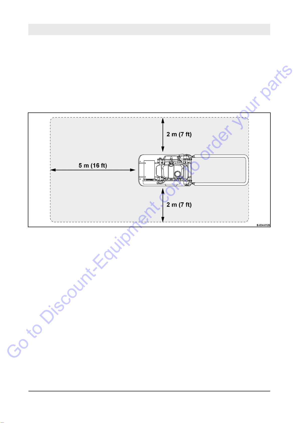
Persons in the danger zone
Before taking up work, also after breaks, you should always convince yourself that the danger zone is free of persons or obstructions.
Give warning signals, if necessary. Stop work immediately if persons remain in the danger zone, despite the warning.
Fig. 6: Danger zone
3.7.2 Operation
3.7.3 Parking the machine
Guide the machine only by the guide handle.
Guide the machine so that your hands do not hit against solid
objects.
W
atch out for unusual noises and development of smoke. Perform
trouble shooting and have the fault corrected.
Always keep a safe distance to excavation pit borders, embankments and edges.
Refrain from any work that could adversely affect the stability of the
machine.
Observe the daily vibration load (work safety acc. to 2002/44/EC).
Park the machine on horizontal, level, firm ground.
BVP 10/30
31
Page 32

Concerning your safety – Operation
Go to Discount-Equipment.com to order your parts
Before leaving the machine:
n Shut down the engine,
n Secure the machine against accidental tipping over,
n Secure the machine against unauthorized use.
Mark machines, which could be in the way, with a clearly visible
sign.
32
BVP 10/30
Page 33

3.8 Refuelling
Go to Discount-Equipment.com to order your parts
Concerning your safety – Refuelling
Do not inhale any fuel fumes.
Refuel only with the engine shut down.
Do not refuel in closed rooms.
No open fire, do not smoke.
Keep away from ignition and heat sources.
Apply measures against electrostatic charging.
Do not spill any fuel. Catch running out fuel, do not let it seep into
the ground.
Wipe of
A leaking fuel tank can cause an explosion. Ensure tight fit of the
fuel tank cover, if necessary replace immediately.
f spilled fuel. Keep dirt and water away from the fuel.
33
BVP 10/30
Page 34

Concerning your safety – Maintenance work
Go to Discount-Equipment.com to order your parts
3.9 Maintenance work
3.9.1
Preliminary remarks
3.9.2 Working on the engine
Adhere to the specified operating, maintenance and repair measures.
The machine must only be serviced by qualified personnel authorised by the operating company.
Keep unauthorised persons away from the machine.
Perform maintenance work only with the engine shut down and the
spark plug connector disconnected.
Do not touch hot components.
Do not leave any tools or other objects, that could cause damage,
in or on the machine.
Drain the engine oil at operating temperature – danger of scalding!
Wipe off spilled oil, catch running out oil and dispose of environmentally.
When working on the air filter no dirt should fall into the air duct.
Do not work on the hot exhaust - danger of burning!
Store used filters and other oil contaminated materials in a separate, specially marked container and dispose of environmentally.
3.9.3 Cleaning work
3.9.4 After maintenance work
Do not perform cleaning work while the motor is running.
Allow the engine to cool down before starting cleaning work.
Do not use gasoline or other easily inflammable substances for
cleaning.
Reassemble all guards and protections.
34
BVP 10/30
Page 35
3.10 Repair
Go to Discount-Equipment.com to order your parts
Concerning your safety – Repair
Identify a defect machine with a warning sign.
Only operate the machine after it has been repaired.
When replacing safety relevant components, only original spare
parts must be used.
Repairs must only be performed by an expert/qualified person.
When performing welding work on the machine you should cover
the fuel tank with insulating material.
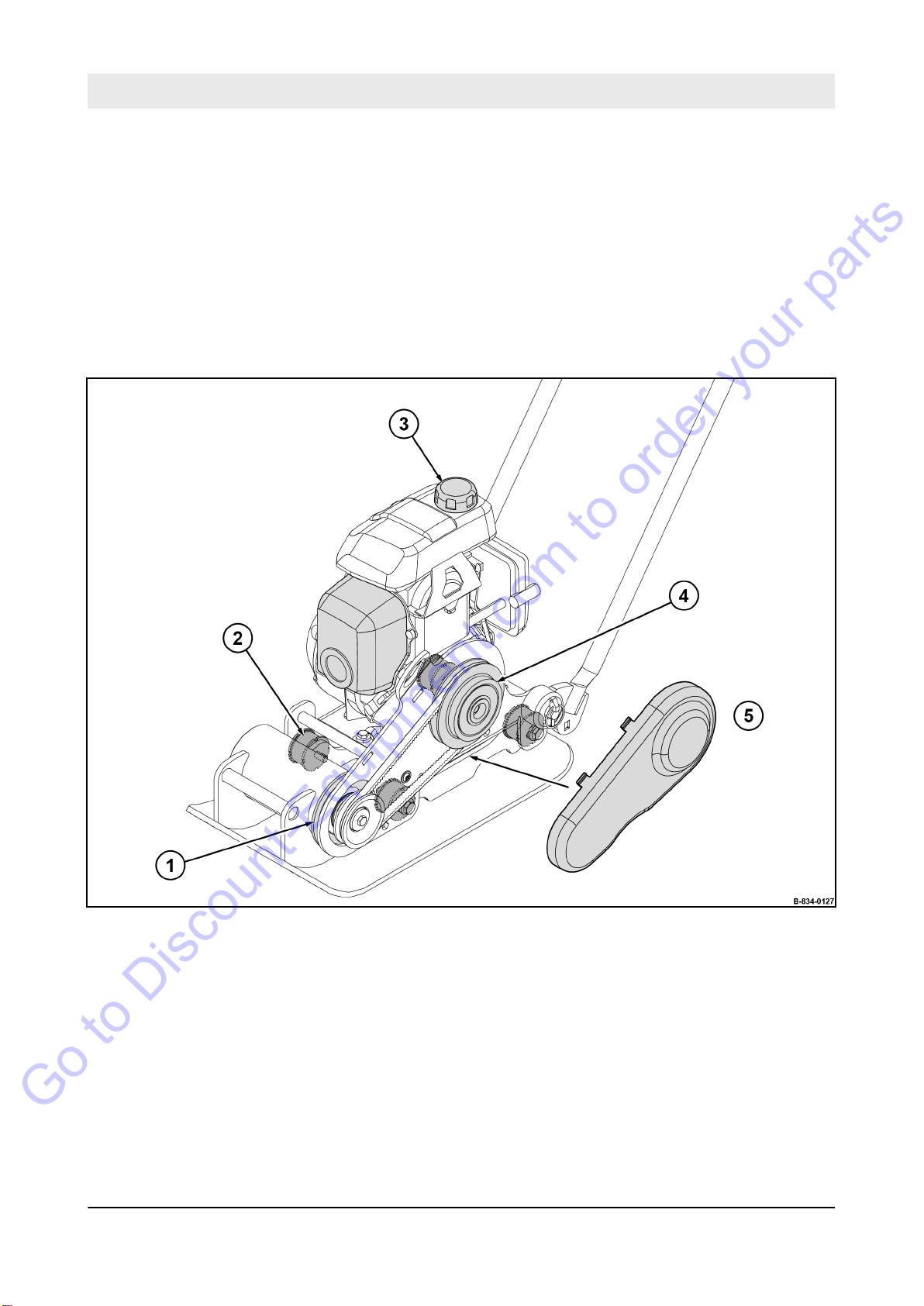
Fig. 7: Safety relevant components
1 Rubber seal
2 Rubber buffer
3 Fuel tank cap
4 Centrifugal clutch
5 V-belt guard
35
BVP 10/30
Page 36
I0
I0
Made by
Designation Type
Nominal Power Operating Mass Year of Construction
Serial-No.
Patent Protection
56154 Boppard;GERMANY Made in Germany
Gasoline/Benzin
WARNING
California Proposition 65 Warning
This product contains chemicals
that cause cancer + chemicals
that are reproductive toxicants
B-834-0301
Concerning your safety – Signage
Go to Discount-Equipment.com to order your parts
3.11 Signage
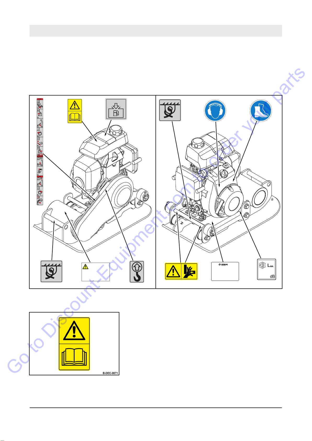
Keep stickers and signage in good and legible condition and
comply with their meaning.
Replace damaged and illegible stickers or signage immediately
.
Fig. 8
Warning sticker - Follow operating instructions
Fig. 9
36
BVP 10/30
Page 37

B-DEC-0284
Fig. 10
WARNING
California Proposition 65 Warning
This product contains chemicals
that cause cancer + chemicals
that are reproductive toxicants
B-DEC-0316
Go to Discount-Equipment.com to order your parts
Concerning your safety – Signage
Warning sticker - Crushing hazard for hands
Warning sticker – California Proposition 65
Fig. 11
Fig. 12
Instruction sticker - Wear ear defenders
Instruction sticker - Wear safety shoes
Fig. 13
37
BVP 10/30
Page 38
B-DEC-0216
Gasoline/Benzin
Concerning your safety – Signage
Go to Discount-Equipment.com to order your parts
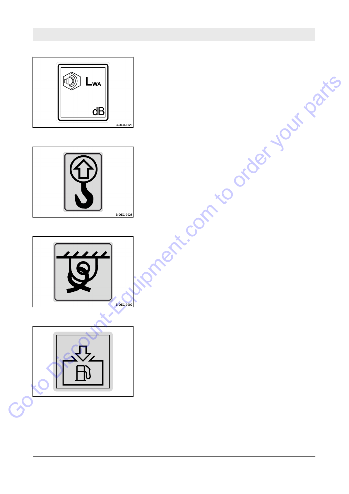
Information sticker - Guaranteed sound capacity level
Fig. 14
Information sticker - Lifting point
Fig. 15
Fig. 16
Information sticker - Lashing point
Information sticker - Filler opening for petrol
Fig. 17
38
BVP 10/30
Page 39
Made by
Designation Type
Nominal Power Operating Mass Year of Construction
Serial-No.
Patent Protection
56154 Boppard;GERMANY Made in Germany
B-DEC-0271
Concerning your safety – Signage
Go to Discount-Equipment.com to order your parts
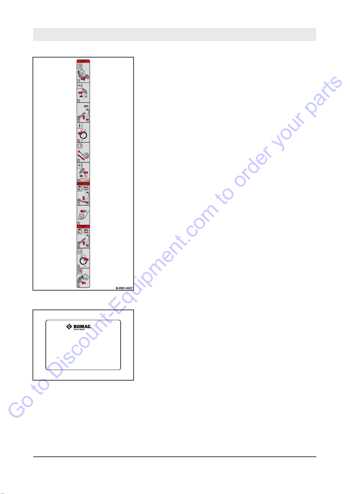
Brief operating instructions
Fig. 18
Machine type plate (example)
Fig. 19
39
BVP 10/30
Page 40
1
2
B-834-0292
Concerning your safety – Safety Components
Go to Discount-Equipment.com to order your parts
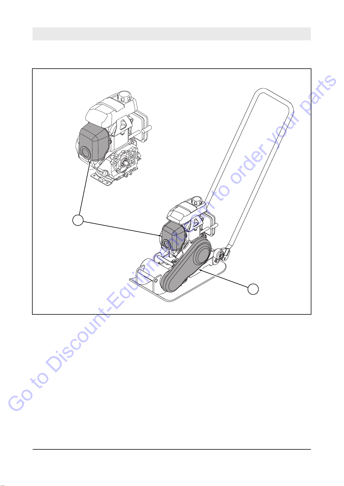
3.12 Safety Components
Fig. 20
1 Heat protection cover
2 Belt guard
40
BVP 10/30
Page 41

4 Machine description
Go to Discount-Equipment.com to order your parts
Machine description
41
BVP 10/30
Page 42
Machine description – Function and design
Go to Discount-Equipment.com to order your parts
4.1 Function and design
This machine is suited for the compaction of gravel, sand and
mixed soils, for smaller repairs in asphalt construction, as well as
for the vibratory compaction of paving stones.
An additional plastic mat must be used for the vibratory compaction
of paving stones to prevent damaging the stone surface.
All other materials can be compacted without the plastic mat.
The plastic mat is available as an accessory
.
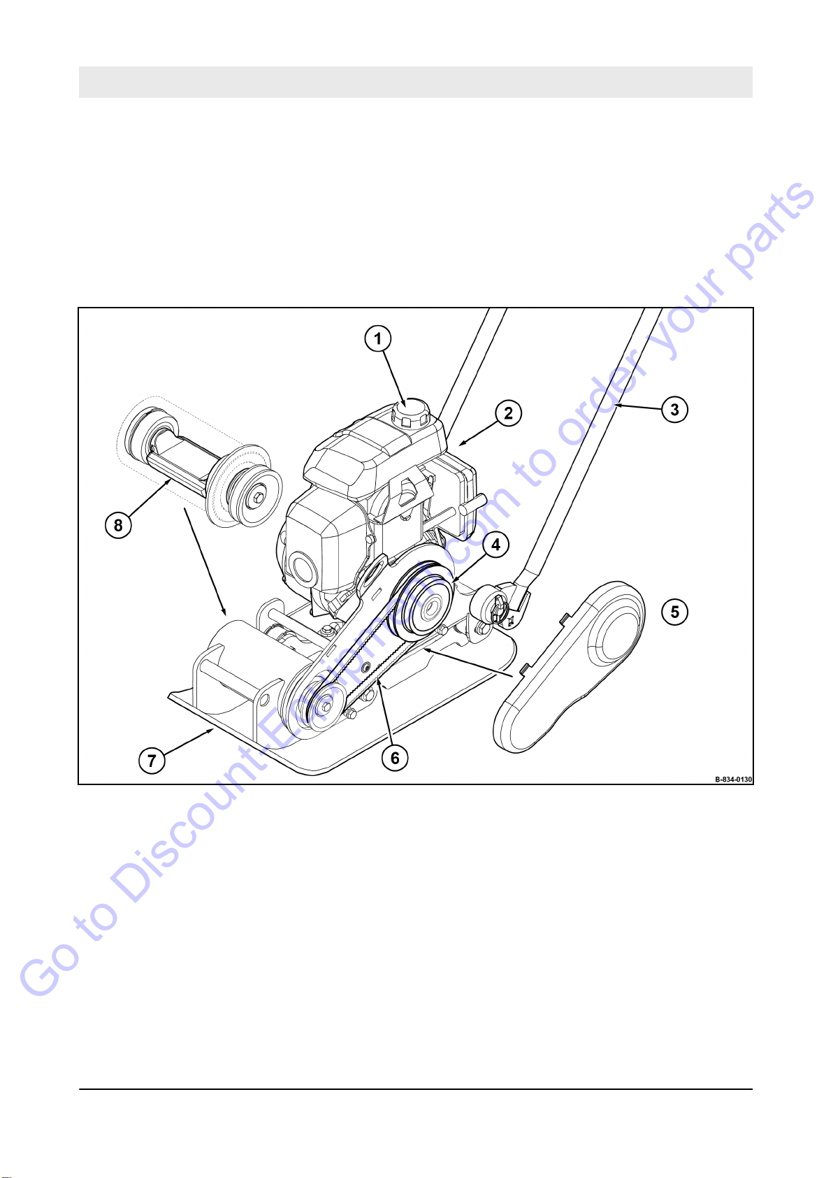
Fig. 21
1 Fuel tank
2 Engine
3 Guide handle
4 Centrifugal clutch
5 V-belt guard
6 V-belt
7 Base plate
8 Exciter shaft
The compaction is achieved by the vibration of the base plate (7).
42
The base plate vibration and the machine’
generated by the exciter shaft (8).
If the engine (2) is running at idle speed, there is no power transmission to the exciter shaft.
BVP 10/30
s forward movement are
Page 43
Models
Go to Discount-Equipment.com to order your parts
Machine description – Function and design
Only when the engine speed increases does the centrifugal clutch
(4) engage and the engine speed is transmitted to the exciter shaft
via the V-belt (6).
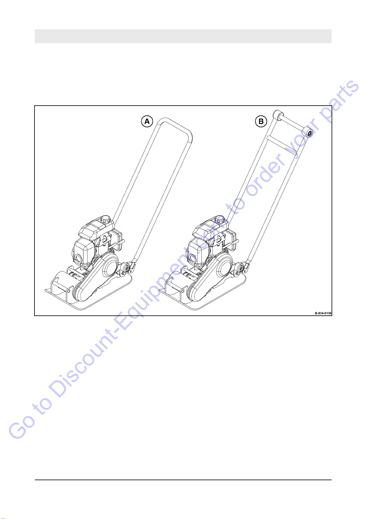
Fig. 22
The machine is available in two models:
A - Machine with standard guide handle
B - Machine with comfort guide handle (reduced hand-arm vibra-
tions)
43
BVP 10/30
Page 44
Machine description – Function and design
Go to Discount-Equipment.com to order your parts
Accessories
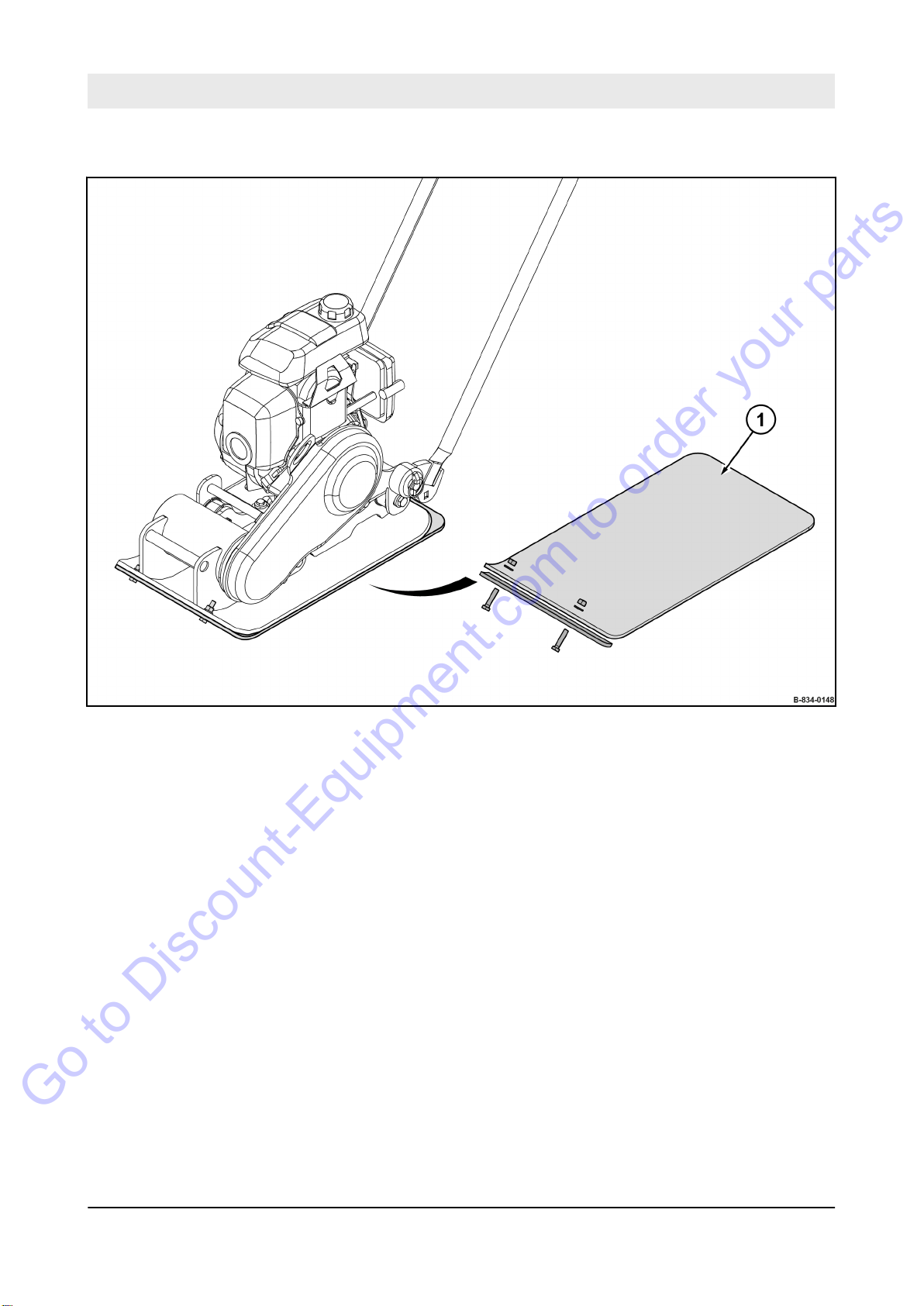
Fig. 23
1 Plastic mat for the vibratory compaction of paving stones
44
BVP 10/30
Page 45
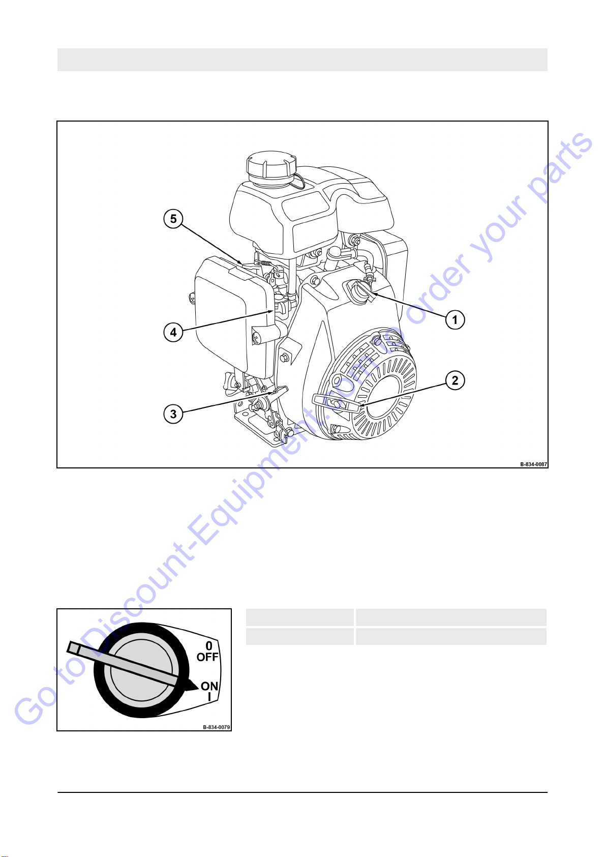
Machine description – Indicators and control elements
Go to Discount-Equipment.com to order your parts
4.2 Indicators and control elements
Fig. 24
1 Starter switch
2 Recoil starter
3 Throttle lever
4 Fuel valve
5 Choke lever
4.2.1 Starter switch
Fig. 25
Position “OFF” Ignition off
Position “ON” Ignition on
45
BVP 10/30
Page 46
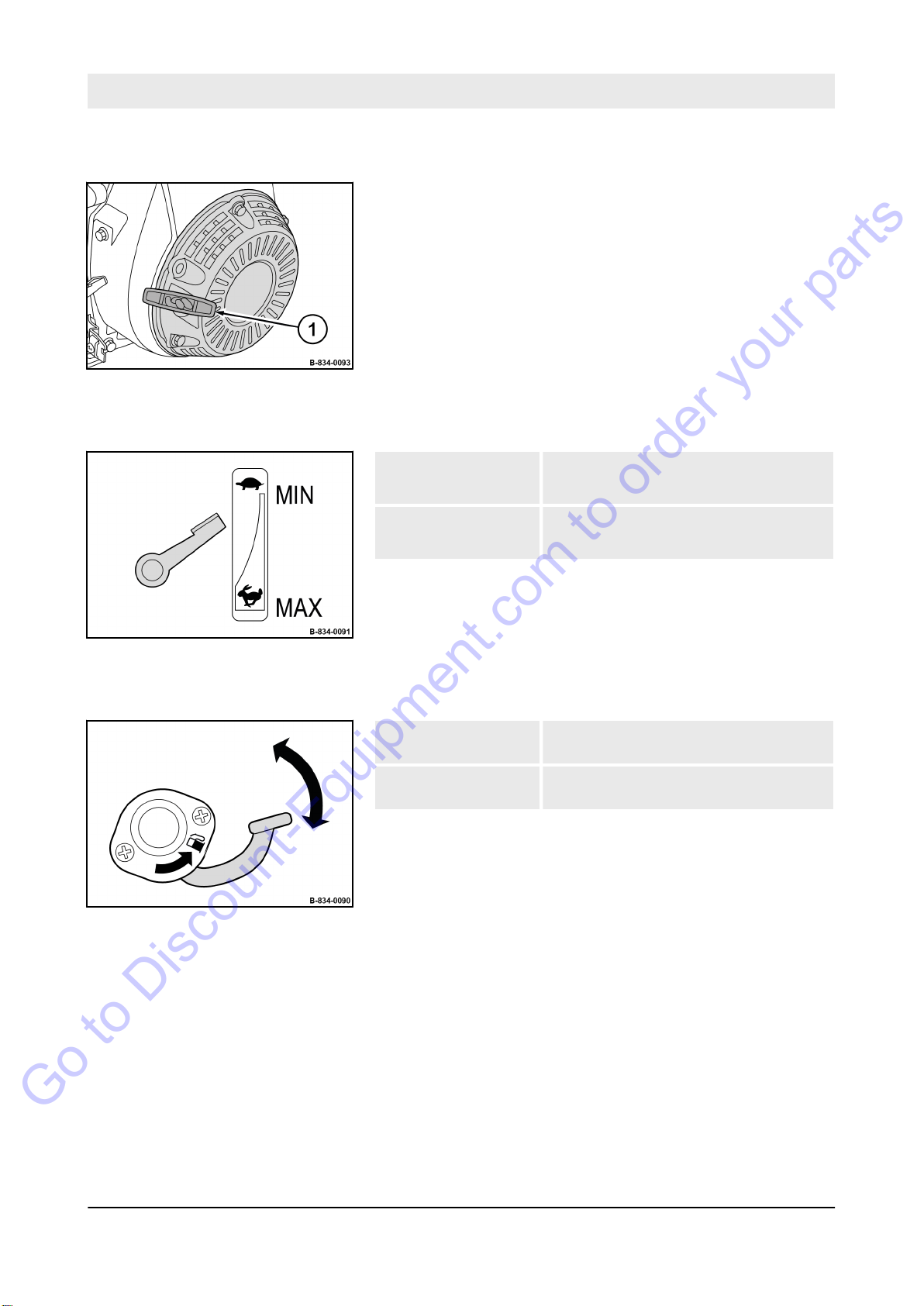
Machine description – Indicators and control elements
Go to Discount-Equipment.com to order your parts
4.2.2 Recoil starter
1 Starter handle
Fig. 26
4.2.3 Throttle lever
Position “Top” Position “MIN”
Idle speed
Position “Bottom” Position “MAX”
maximum engine speed
Fig. 27
4.2.4 Fuel valve
Fig. 28
Turn the lever in the
arrow direction
Turn the lever against
the arrow direction
Open the fuel valve
Close the fuel cock
46
BVP 10/30
Page 47

4.2.5 Choke lever
Go to Discount-Equipment.com to order your parts
Machine description – Indicators and control elements
Fig. 29
Turn the lever in the
arrow direction
Turn the lever against
the arrow direction
Close the choke only when with the engine is cold.
If the engine is warm or the outside temperatures
are high, the choke must remain open to prevent
the engine from stalling.
Close the choke
Open the choke
47
BVP 10/30
Page 48

Checks prior to start up
Go to Discount-Equipment.com to order your parts
5 Checks prior to start up
49
BVP 10/30
Page 49
Checks prior to start up – Notes on safety
Go to Discount-Equipment.com to order your parts
5.1 Notes on safety
If the following tests reveal damages or other defects, the machine
must not be operated, until these deficiencies have been corrected.
Do not operate the machine with defective indicators and control
elements.
Safety installations must not be removed or made inef
Do not change any fixed settings.
WARNING!
Health hazard caused by fuels and lubricants!
– Safety regulations and environmental protec-
WARNING!
Danger of injury caused by rotating parts!
– Before starting work on the machine make sure
fective.
tion regulations must be followed when han-
Ä
dling fuels and lubricants
dling fuels and lubricants’ on page 25.
that the engine can not be started.
Chapter 3.4 ‘Han-
1.
Park the machine safely
in secured condition’ on page 74.
Ä
Chapter 6.6 ‘Parking the machine
50
BVP 10/30
Page 50
Checks prior to start up – Visual inspections and function tests
Go to Discount-Equipment.com to order your parts
5.2 Visual inspections and function tests
Machine
Screw connections
Fuel tank and fuel lines
Protective equipment:
1.
Park the machine in secured condition
‘Parking the machine in secured condition’ on page 74.
2. Check machine for contamination and damage.
Remove waste such as paper
ð
If necessary, have the machine cleaned by our customer
service.
Have damaged components replaced by our customer
service immediately.
3. Check the screw connections on the machine regarding con-
dition and tight fit.
Have loose or damaged screw connections checked and,
ð
if necessary
ately.
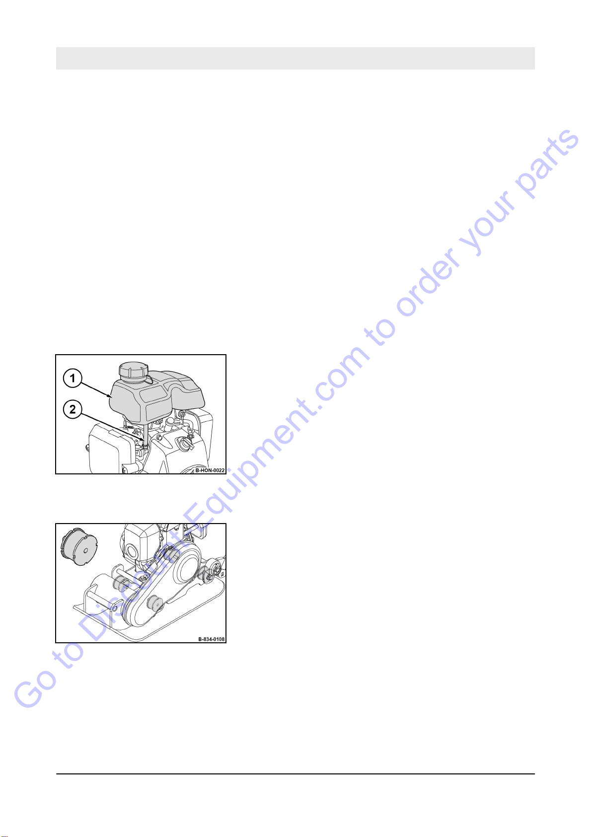
4. Check fuel tank (1) and fuel hose (2) for condition and leaks.
Have a damaged fuel tank or fuel hose replaced by our
ð
customer service immediately
, replaced by our customer service immedi-
orking clothes
W
n
Protective gloves
n
Ä
Chapter 6.6
, leaves or grass.
.
Fig. 30
Rubber buffer
Fig. 31
5. Check all rubber buf
Have damaged rubber buffers replaced by our customer
ð
service immediately.
fers for tight fit, cracks and tear-offs.
51
BVP 10/30
Page 51
Checks prior to start up – Visual inspections and function tests
Go to Discount-Equipment.com to order your parts
Air intake area
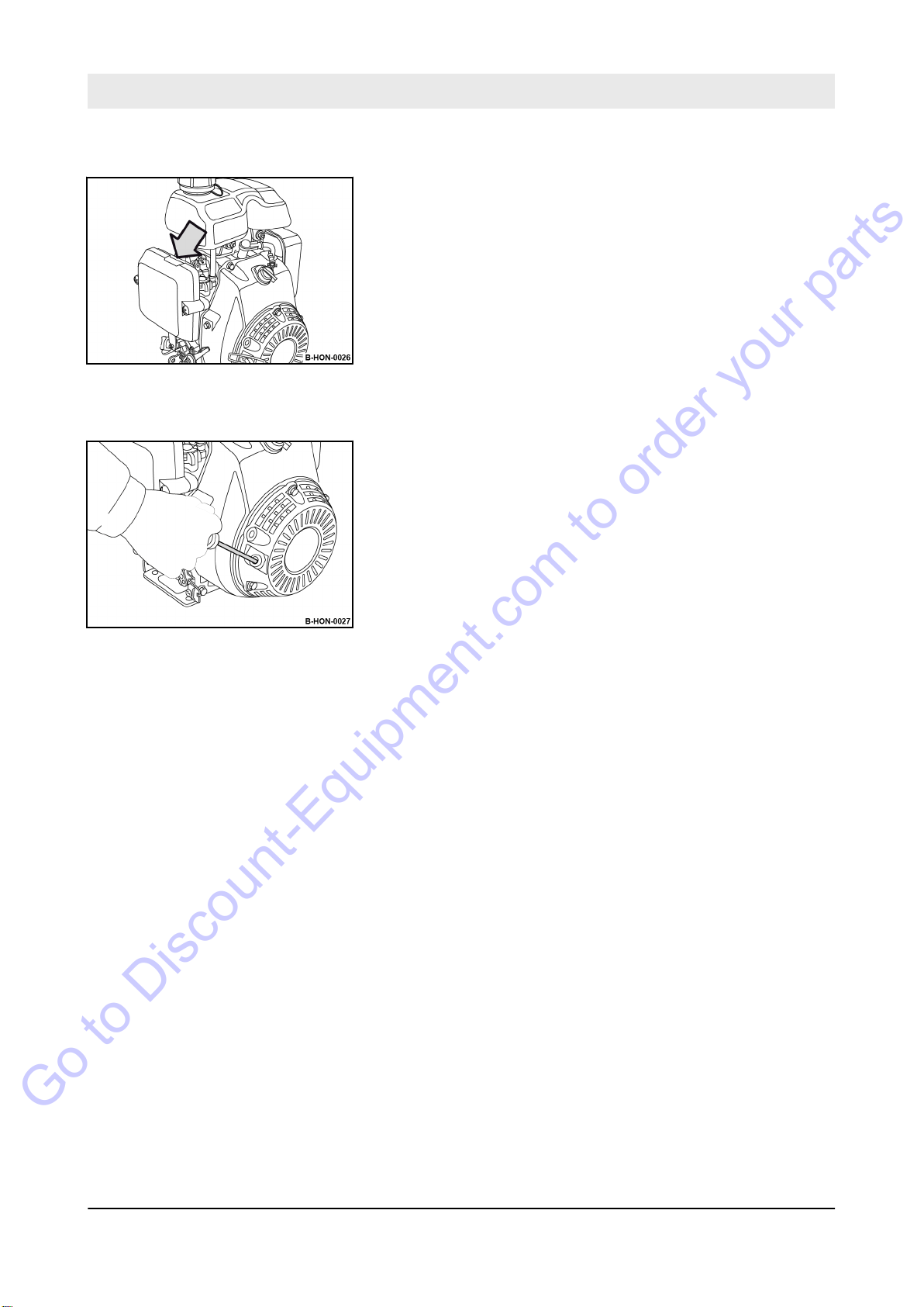
6. Check the air intake area for dirt.
Remove contamination.
ð
Fig. 32
Starter rope
7. Check the condition of the starter rope.
Have the damaged starter rope (
ð
cracks) replaced by our customer service immediately.
e.g. chafing points,
Fig. 33
52
BVP 10/30
Page 52
Checks prior to start up – Checking the engine oil level
Go to Discount-Equipment.com to order your parts
5.3 Checking the engine oil level
NOTICE!
Danger of engine damage!
– +Use only oil of the permitted specification
Ä
Chapter 8.2.1 ‘Engine oil’ on page 87.
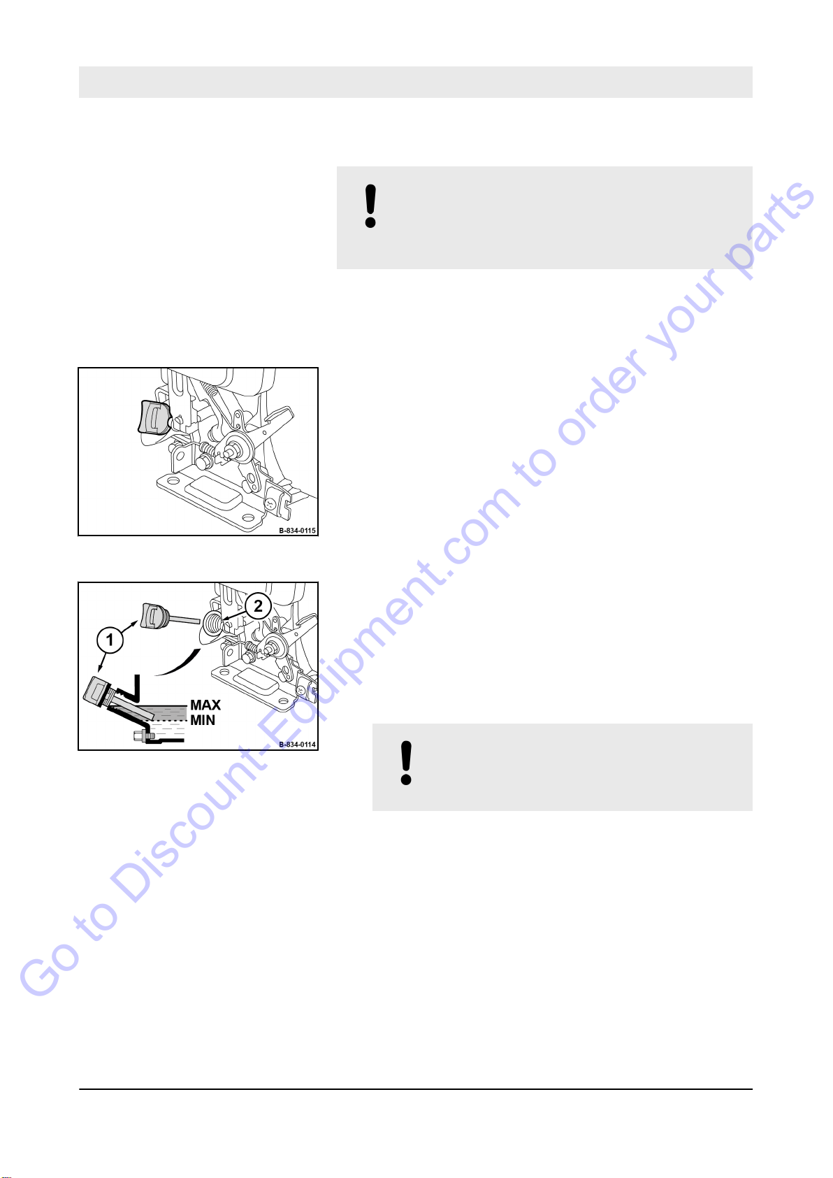
Fig. 34
Fig. 35
Protective equipment:
1.
Park the machine in secured condition
‘Parking the machine in secured condition’ on page 74.
2. Clean the area around the filler opening.
3. Pull out the dipstick (1) and wipe it clean with a lint-free,
clean cloth.
4. Insert the dipstick into the filler opening (2) without screwing
it in.
5. Pull the dipstick out again.
The oil level must be between the “MIN” and “MAX”
ð
marks.
6.
NOTICE!
Danger of engine damage!
– Do not fill in too much engine oil.
orking clothes
W
n
Protective gloves
n
Ä
Chapter 6.6
If the oil level is too low, top up engine oil to the “MAX” mark.
7. Screw the oil dipstick in.
53
BVP 10/30
Page 53
Checks prior to start up – Checking the fuel level, topping up fuel
Go to Discount-Equipment.com to order your parts
5.4 Checking the fuel level, topping up fuel
DANGER!
Danger to life caused by explosive gas-air
mixes!
– Do not allow gasoline to come into contact with
hot components.
Smoking and open fire is prohibited.
–
– Keep away from heat sources, sparks and
other sources of ignition.
– Do not spill any gasoline.
NOTICE!
Danger of engine damage!
– Monitor the entire refuelling process.
– Contaminated fuel can cause malfunction or
even damage of the engine. If necessary, fill in
fuel through a screen filter.
– Use only fuel of the permitted specification
Ä
Chapter 8.2.2 ‘Fuel’ on page 87.
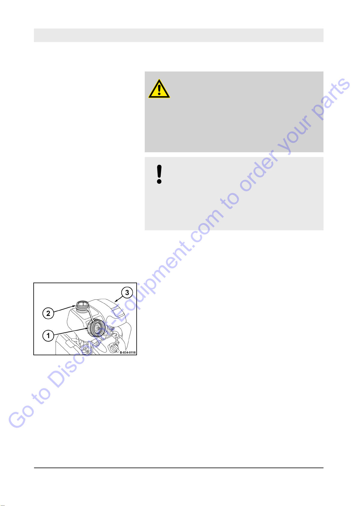
Fig. 36
Protective equipment:
1.
Park the machine in secured condition
‘Parking the machine in secured condition’ on page 74.
2. Let the machine and the engine cool down.
3. Clean the area around the filler opening (2).
4. Unscrew the cap (1).
5. Check the fuel level on the fuel tank (3).
6. Fill in fuel through a funnel with screen filter
7. Screw the cap on.
orking clothes
W
n
Protective gloves
n
Ä
Chapter 6.6
.
54
BVP 10/30
Page 54

6 Operation
Go to Discount-Equipment.com to order your parts
Operation
55
BVP 10/30
Page 55

Operation – Initial start-up
Go to Discount-Equipment.com to order your parts
6.1 Initial start-up
1. Remove the packaging material completely
2. Check condition and completeness of the machine.
3. Dispose of the packaging material in an environmentally
friendly way
4.
Carry out checks prior to start up
to start up’ on page 49.
5.
Start the engine
on page 67.
.
Ä
Chapter 5 ‘Checks prior
Ä
Chapter 6.4 ‘Starting the engine’
.
56
BVP 10/30
Page 56
6.2 Guide handle
Go to Discount-Equipment.com to order your parts
Operation – Guide handle
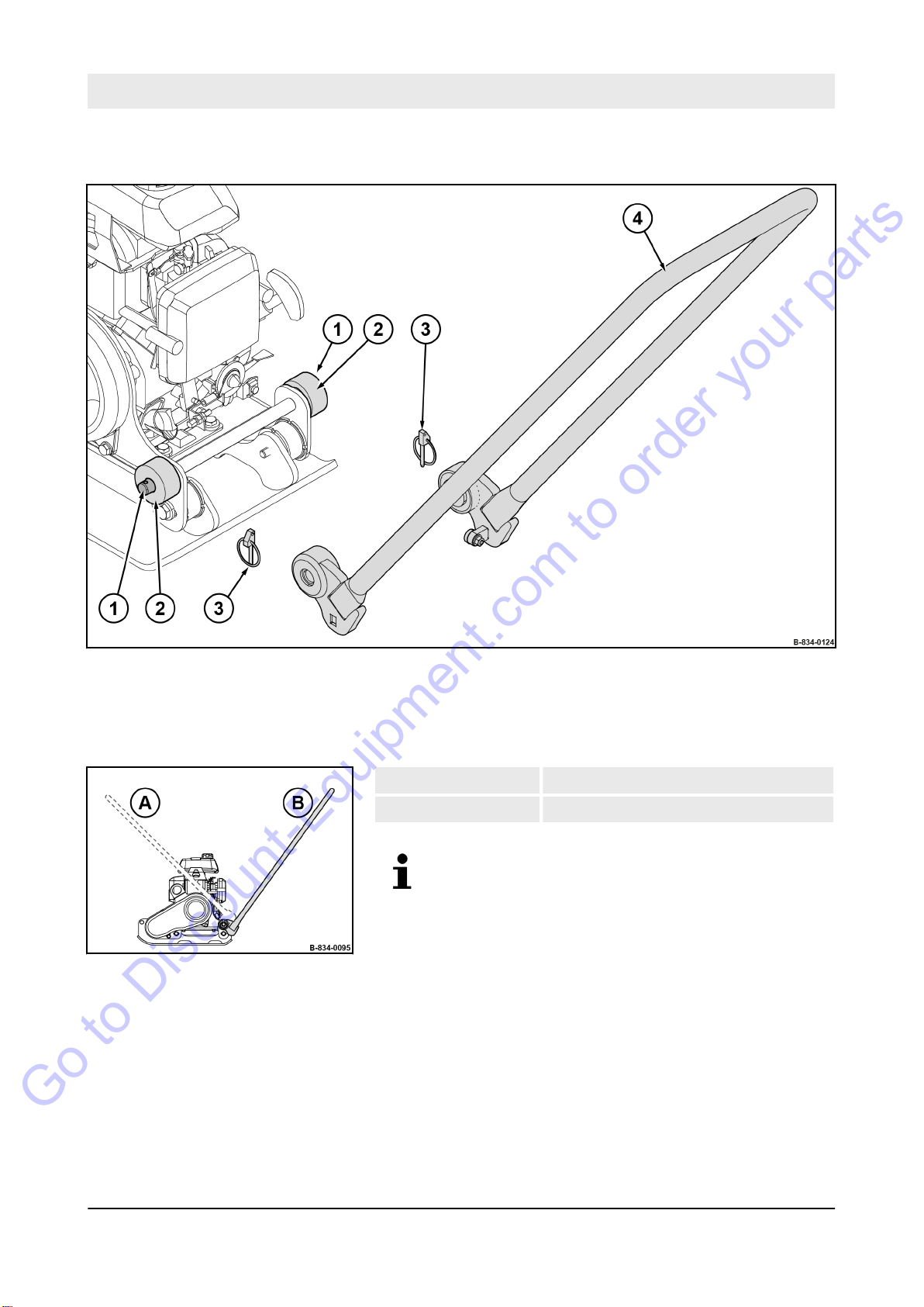
Fig. 37
1 Holding fixture on the machine
2 Buffer
3 Clip pin to secure the guide handle
4 Guide handle
Fig. 38
Position “A” Transport position
Position “B” Working position
The operating possibilities are the same for both
versions of the guide handle.
57
BVP 10/30
Page 57
Operation – Guide handle
Go to Discount-Equipment.com to order your parts
6.2.1 Mounting the guide handle
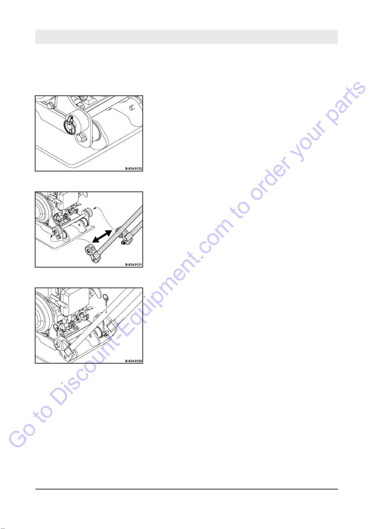
Fig. 39
Protective equipment:
1. If the clip pins are fastened to the holding fixtures:
Unfold clip pins on both sides and remove them.
2. Force the guide handle apart and plug it onto the holding fix-
tures.
orking clothes
W
n
Protective gloves
n
Fig. 40
Fig. 41
3. Insert the clip pins through the bore on the holding fixtures.
58
BVP 10/30
Page 58

Fig. 42
Go to Discount-Equipment.com to order your parts
Operation – Guide handle
4. Fold down the clip pins on both sides.
59
BVP 10/30
Page 59
Operation – Guide handle
Go to Discount-Equipment.com to order your parts
6.2.2 Removing the guide handle
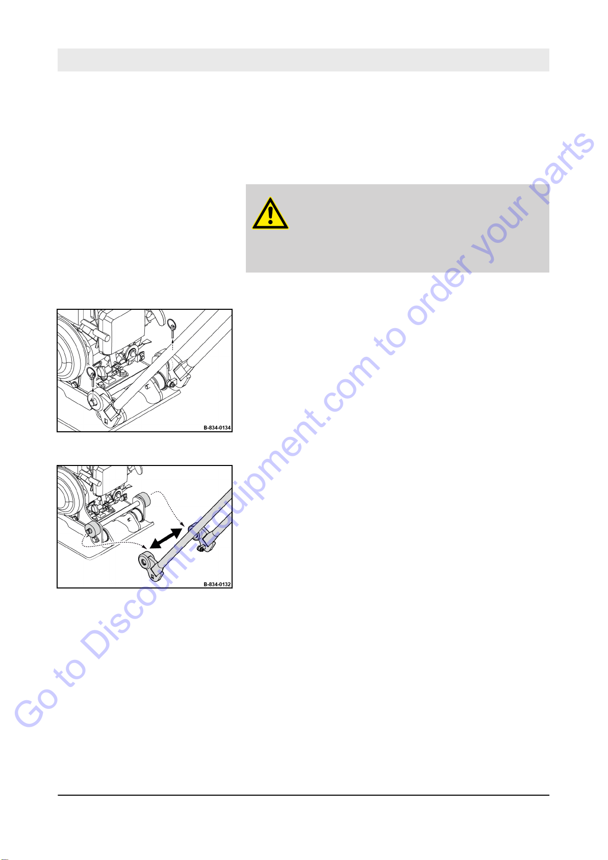
Protective equipment:
1.
Park the machine in secured condition
‘Parking the machine in secured condition’ on page 74.
WARNING!
Danger of burning on hot components!
– Wear your personal protective equipment (pro-
tective gloves, protective clothing).
–
Avoid touching hot components.
2. Let the machine and the engine cool down to ambient tem-
perature.
3. Unfold clip pins on both sides and remove them.
Protective gloves
n
orking clothes
W
n
Ä
Chapter 6.6
Fig. 43
Fig. 44
4. Force the guide handle apart and remove it from the holding
fixtures.
60
BVP 10/30
Page 60

Fig. 45
Go to Discount-Equipment.com to order your parts
Operation – Guide handle
5. Insert the clip pins through the bore of the holding fixtures
and fold them down.
61
BVP 10/30
Page 61
Operation – Plastic mat
Go to Discount-Equipment.com to order your parts
6.3 Plastic mat
Use a plastic mat for the vibratory compaction of paving stones to
prevent damaging the stone surface.
All other materials are compacted without the plastic mat.
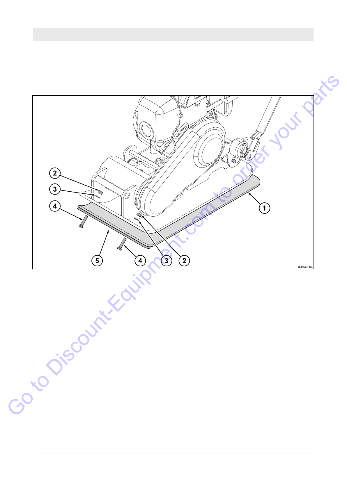
Fig. 46
1 Plastic mat
2 Fastening nut
3 Washer
4 Fastening screw
5 Clamping strip
62
BVP 10/30
Page 62
6.3.1 Mount the plastic mat
Go to Discount-Equipment.com to order your parts
Operation – Plastic mat
Protective equipment:
1.
Park the machine in secured condition
‘Parking the machine in secured condition’ on page 74.
WARNING!
Danger of burning on hot components!
– Wear your personal protective equipment (pro-
tective gloves, protective clothing).
–
Avoid touching hot components.
2. Let the machine and the engine cool down to ambient tem-
perature.
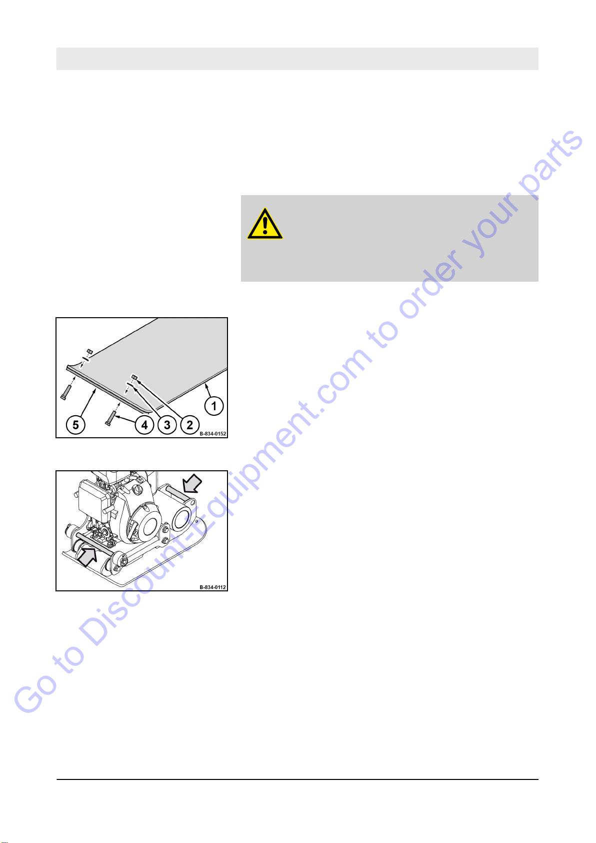
3. If the attachment parts (2 - 5) are screwed to the plastic mat
(1):
Remove the fastening nuts (2) of the plastic mat (1) on both
sides.
Remove washers (3), fastening screws (4) and clamping strip
(5).
orking clothes
W
n
Protective gloves
n
Safety shoes
n
Ä
Chapter 6.6
Fig. 47
Fig. 48
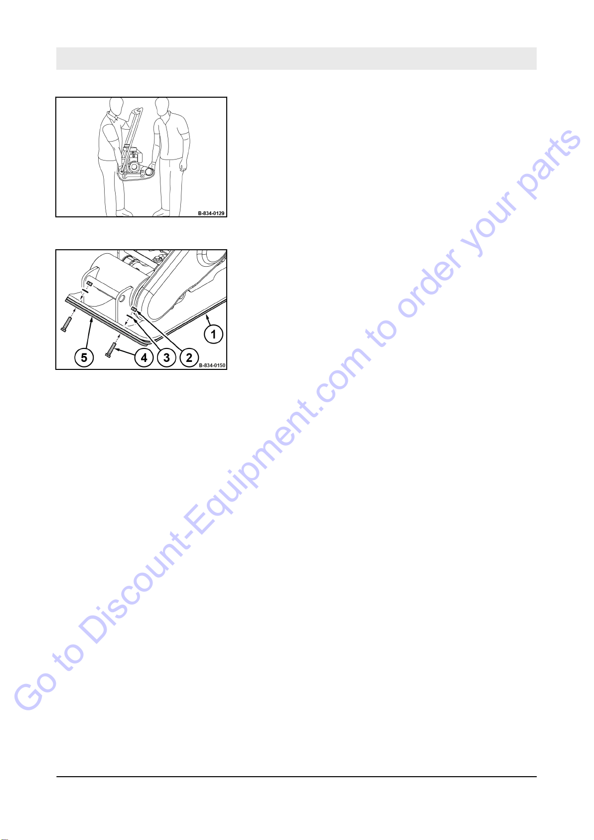
4. Check all lashing points including fastening elements for
damage before lifting the machine.
Do not use damaged or in any other way impaired
ð
lashing points.
63
BVP 10/30
Page 63
Operation – Plastic mat
Go to Discount-Equipment.com to order your parts
Fig. 49
5. Lift the machine with the help of a second person by means
of the lashing points.
6. Hold the guide handle with one hand when lifting.
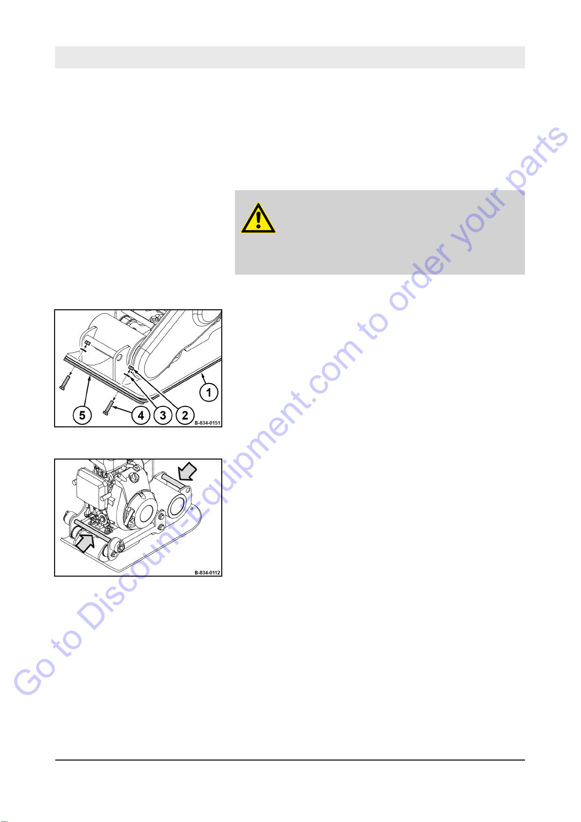
7. Set the machine down on the plastic mat (1).
8. Place the clamping strip (5) onto the plastic mat at the
bottom.
9. Screw the plastic mat and clamping strip onto both sides of
the base plate using fastening screws (4), washers (3) and
fastening nuts (2).
Fig. 50
64
BVP 10/30
Page 64
6.3.2 Removing the plastic mat
Go to Discount-Equipment.com to order your parts
Operation – Plastic mat
Protective equipment:
1.
Park the machine in secured condition
‘Parking the machine in secured condition’ on page 74.
WARNING!
Danger of burning on hot components!
– Wear your personal protective equipment (pro-
tective gloves, protective clothing).
–
Avoid touching hot components.
2. Let the machine and the engine cool down to ambient tem-
perature.
3. Remove the fastening nuts (2) of the plastic mat (1) on both
sides.
4. Remove washers (3), fastening screws (4) and clamping strip
(5).
orking clothes
W
n
Protective gloves
n
Safety shoes
n
Ä
Chapter 6.6
Fig. 51
Fig. 52
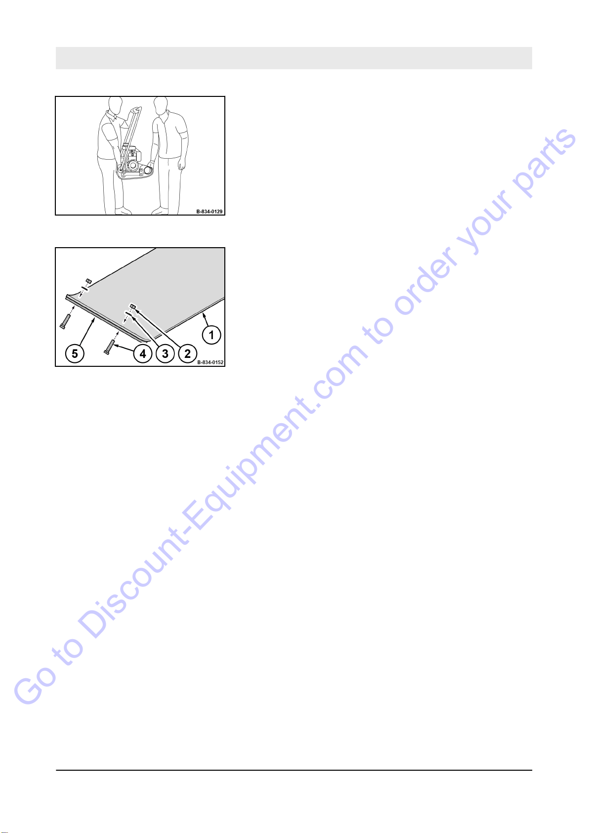
5. Check all lashing points including fastening elements for
damage before lifting the machine.
Do not use damaged or in any other way impaired
ð
lashing points.
65
BVP 10/30
Page 65
Operation – Plastic mat
Go to Discount-Equipment.com to order your parts
Fig. 53
6. Lift the machine with the help of a second person by means
of the lashing points.
7. Hold the guide handle with one hand when lifting.
8. Park the machine on level, firm ground.
9. Screw the clamping strip (5) onto both sides of the plastic
mat using fastening screws (4), washers (3) and fastening
nuts (2).
Fig. 54
66
BVP 10/30
Page 66
6.4 Starting the engine
Go to Discount-Equipment.com to order your parts
Operation – Starting the engine
Exhaust fumes contain toxic substances and can damage your
health, cause unconsciousness or even death.
WARNING!
Danger of poisoning by exhaust gases!
– Do not inhale exhaust gases.
Avoid operation in closed or partly closed
–
rooms, or ensure adequate ventilation when
working in trenches.
Components can be very hot during or immediately after operation.
WARNING!
Danger of burning on hot components!
– Wear your personal protective equipment (pro-
tective gloves, protective clothing).
– Avoid touching hot components.
WARNING!
Loss of hearing caused by too high noise bur-
dens!
– Wear your personal protective equipment (ear
protection).
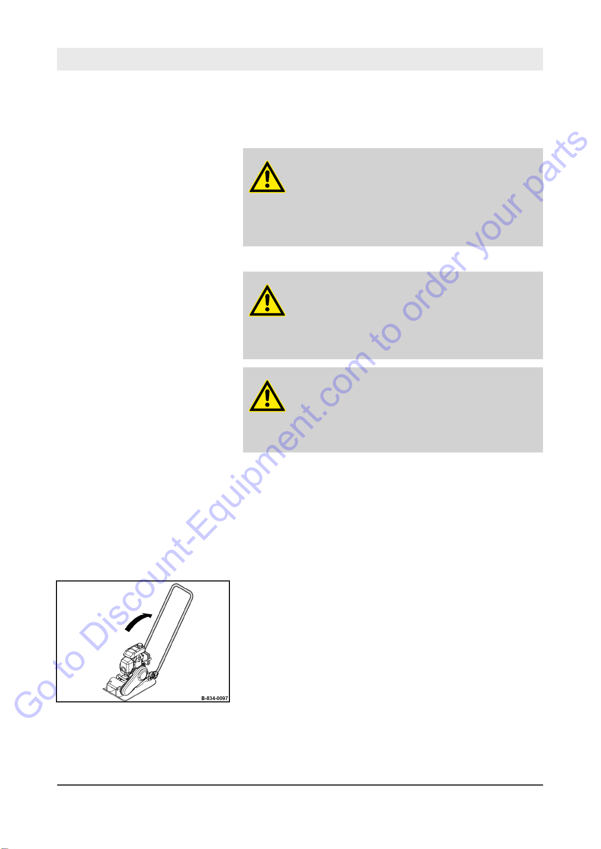
Operate the machine only with the guide handle mounted and lowered.
Protective equipment:
1.
Mounting the guide handle Ä Chapter 6.2.1 ‘Mounting the
guide handle’ on page 58.
2. Fold down the guide handle into working position.
3. Make sure that no persons are in the danger zone.
Hearing protection
n
Working clothes
n
Protective gloves
n
Safety shoes
n
Fig. 55
67
BVP 10/30
Page 67
Operation – Starting the engine
Go to Discount-Equipment.com to order your parts
Fig. 56
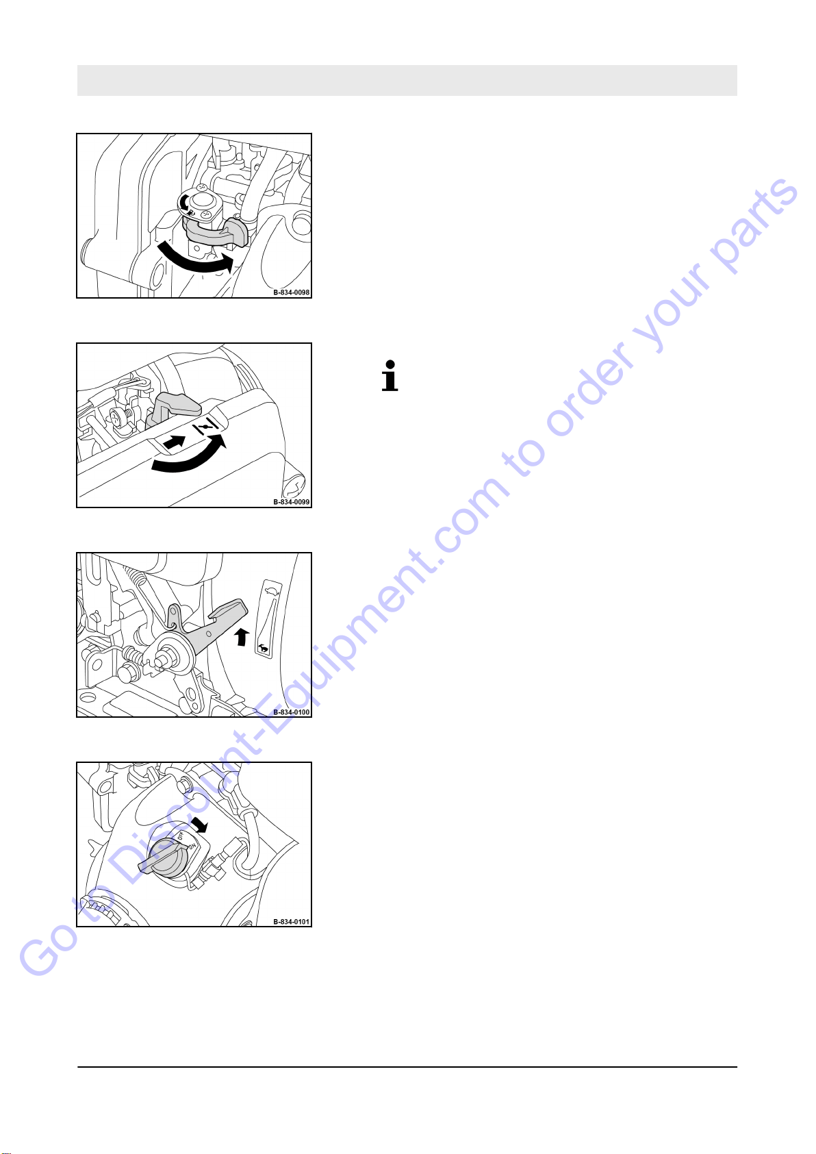
4. Open the fuel tap completely.
5.
Close the choke only when with the engine is
cold.
If the engine is warm or the outside temperatures are high, the choke must remain open
to prevent the engine from stalling.
Close the choke with the choke lever.
Fig. 57
Fig. 58
6. Set the throttle lever to position “MIN”.
7. T
urn the starter switch to position “ON”.
Fig. 59
68
BVP 10/30
Page 68
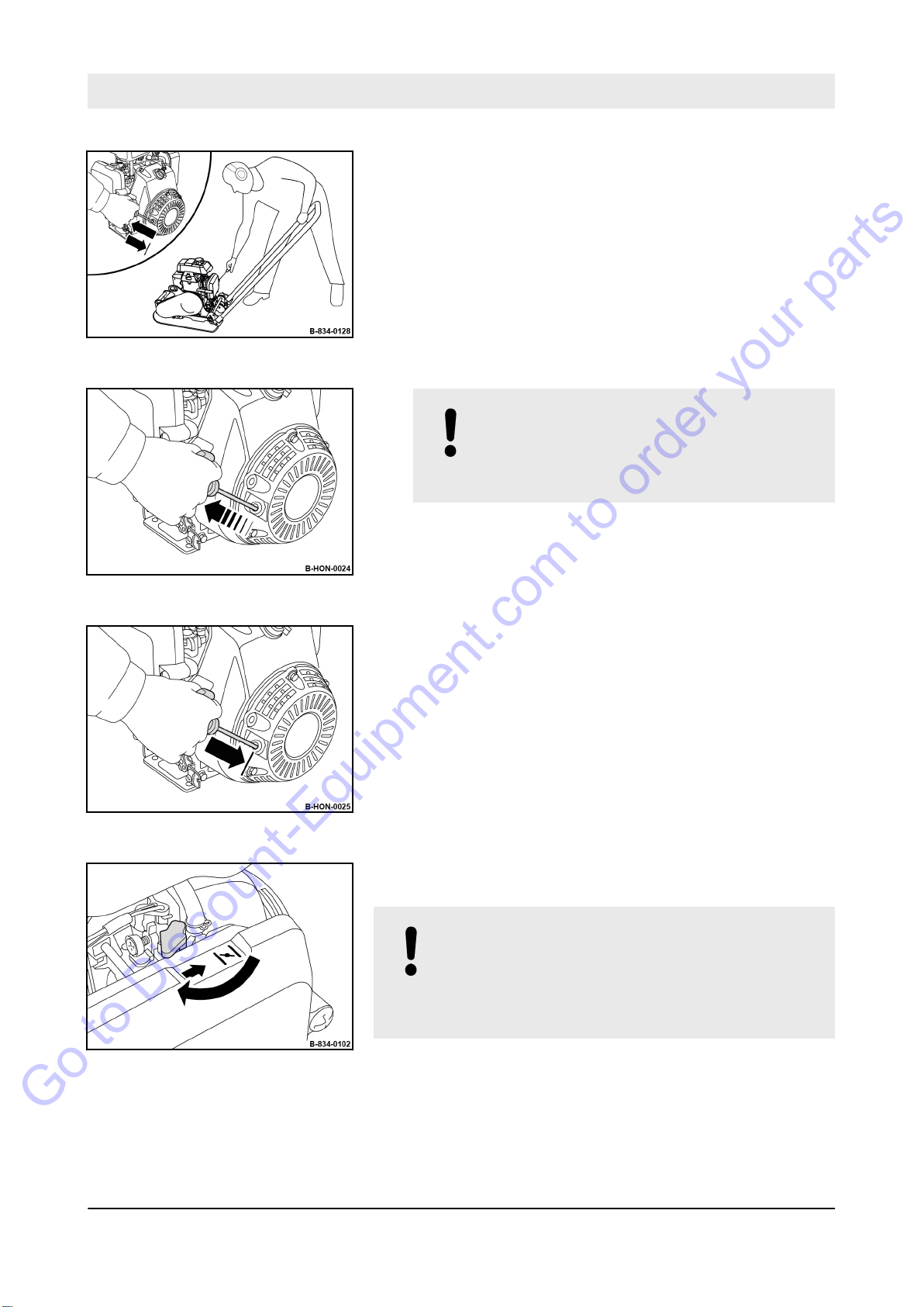
Fig. 60
Go to Discount-Equipment.com to order your parts
Operation – Starting the engine
8. Stand behind the machine on one side and hold the
machine’s guide handle with one hand.
9. Using the other hand, pull the rope by the starter handle, until
resistance can be felt.
10. Guide the starter handle back to initial position.
11.
NOTICE!
The starter rope may tear off!
– Do not pull the starter rope all the way
against the end stop.
Pull the starter handle quickly and with power.
The engine starts.
ð
Fig. 61
Fig. 62
12. Manually guide the starter handle back to initial position.
13. If the engine does not start during the first attempt, repeat the
starting process.
14. When the engine is running, open the lever of the choke bit
by bit.
NOTICE!
Danger of engine damage!
– Warm up engine for a short while before
starting work. Do not operate the engine immediately under full load.
Fig. 63
15. Run the engine warm for approx. 1 to 2 minutes in idle
speed.
At idle speed vibration is switched of
ð
69
BVP 10/30
f.
Page 69

Operation – Starting the engine
Go to Discount-Equipment.com to order your parts
Fig. 64
16. Should the engine stop again after approx. 3 to 5 seconds:
n Close the choke again using the choke lever.
n Repeat the starting procedure.
If the recoil starter is frequently operated with the
choke closed and without the engine starting, the
engine will draw in too much fuel and is unable to
Ä
start
flooded’ on page 118.
Chapter 9.3 ‘What to do if the engine has
70
BVP 10/30
Page 70

6.5 Operation
Go to Discount-Equipment.com to order your parts
Operation – Operation
Guide the machine only by the guide handle.
Guide the machine so that your hands do not hit against solid
objects.
Keep feet clear of the vibrating base plate.
CAUTION!
Danger of injury caused by uncontrolled
machine movement!
– Always hold on to a running machine.
Always keep an eye on a running machine.
–
71
BVP 10/30
Page 71
Operation – Operation
Go to Discount-Equipment.com to order your parts
Components can be very hot during or immediately after operation.
WARNING!
Danger of burning on hot components!
– Wear your personal protective equipment (pro-
tective gloves, protective clothing).
–
Avoid touching hot components.
WARNING!
Loss of hearing caused by too high noise bur-
dens!
– Wear your personal protective equipment (ear
protection).
Protective equipment:
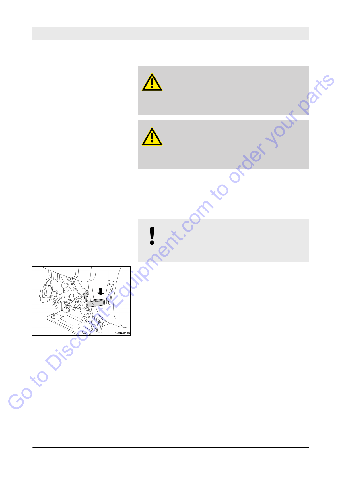
1. Make sure that no persons are in the danger zone.
NOTICE!
The centrifugal clutch may be damaged!
– Operate the machine only with the throttle lever
in position “MAX”.
2. Set the throttle lever to position “MAX”.
Machine vibrates forwards.
ð
Hearing protection
n
orking clothes
W
n
Protective gloves
n
Safety shoes
n
Fig. 65
72
BVP 10/30
Page 72
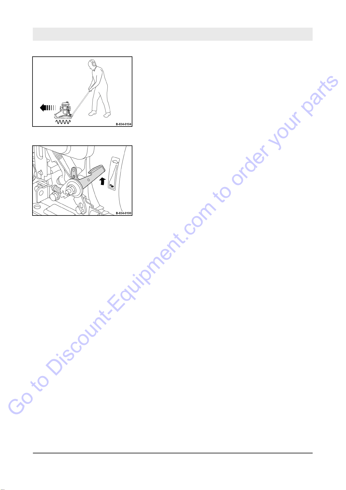
Fig. 66
Go to Discount-Equipment.com to order your parts
Operation – Operation
3. Guide the machine by means of the guide handle.
4. For short work interruptions you should always return the
throttle lever to position “MIN” (idle speed).
V
ibration is switched off.
ð
5. For short work interruptions you should always park the
machine in secured condition
machine in secured condition’ on page 74.
Ä
Chapter 6.6 ‘Parking the
Fig. 67
73
BVP 10/30
Page 73
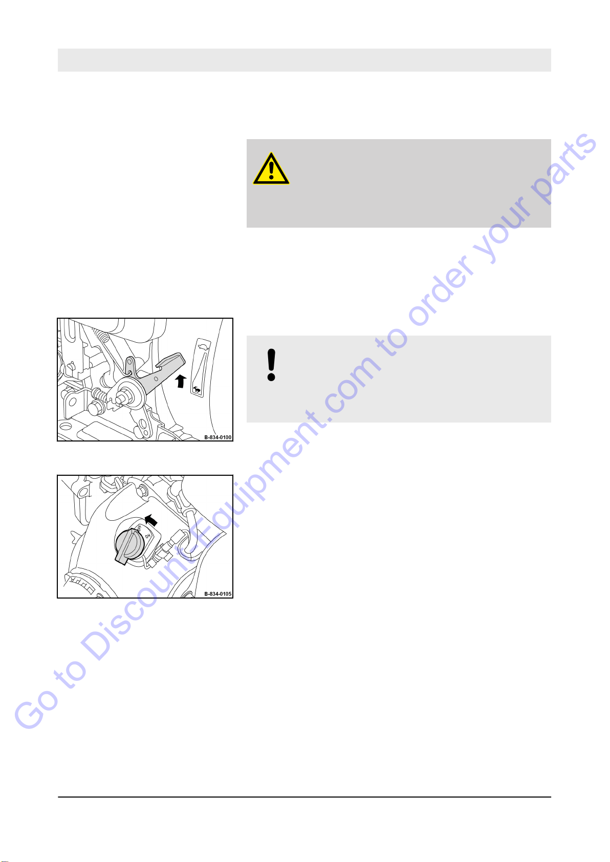
Operation – Parking the machine in secured condition
Go to Discount-Equipment.com to order your parts
6.6 Parking the machine in secured condition
Components can be very hot during or immediately after operation.
WARNING!
Danger of burning on hot components!
– Wear your personal protective equipment (pro-
tective gloves, protective clothing).
Avoid touching hot components.
–
Fig. 68
Protective equipment:
1. Park the machine on level and firm ground.
2. Set the throttle lever to position “MIN” (idle speed).
NOTICE!
Danger of engine damage!
– Do not shut down the engine all of a sudden
from full load speed, but let it idle for about two
minutes.
3. Turn the starter switch to position “OFF”.
The engine is shut down.
ð
Hearing protection
n
orking clothes
W
n
Protective gloves
n
Safety shoes
n
Fig. 69
74
BVP 10/30
Page 74

Fig. 70
Go to Discount-Equipment.com to order your parts
Operation – Parking the machine in secured condition
4. Close the fuel valve completely.
5. Secure the machine against unauthorized use.
75
BVP 10/30
Page 75

Loading / transporting the machine
Go to Discount-Equipment.com to order your parts
7 Loading / transporting the machine
77
BVP 10/30
Page 76
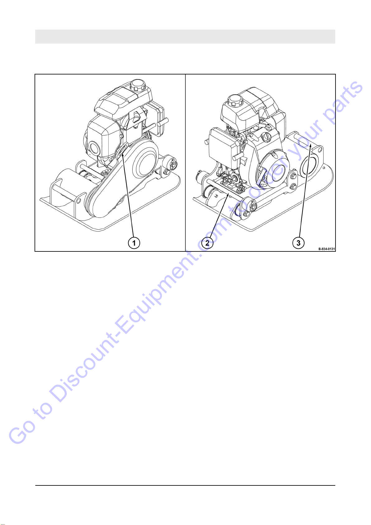
Loading / transporting the machine – Preliminary remarks and safety notes
Go to Discount-Equipment.com to order your parts
7.1 Preliminary remarks and safety notes
Fig. 71
1 Lifting point for lifting tackle
2 Rear lashing point
3 Front lashing point
Observe locally applicable laws and regulations when loading and
transporting.
The machine can be lifted and loaded using lifting gear at the
intended lifting point (1) (
Attaching and hoisting loads with lifting gear must only be performed by an expert / qualified person.
Alternatively the machine can be lifted manually at the lashing
points (2, 3).
Always lift the machine with the help of a second person. The
machine is too heavy to lift alone.
e.g. with a crane).
78
BVP 10/30
Page 77
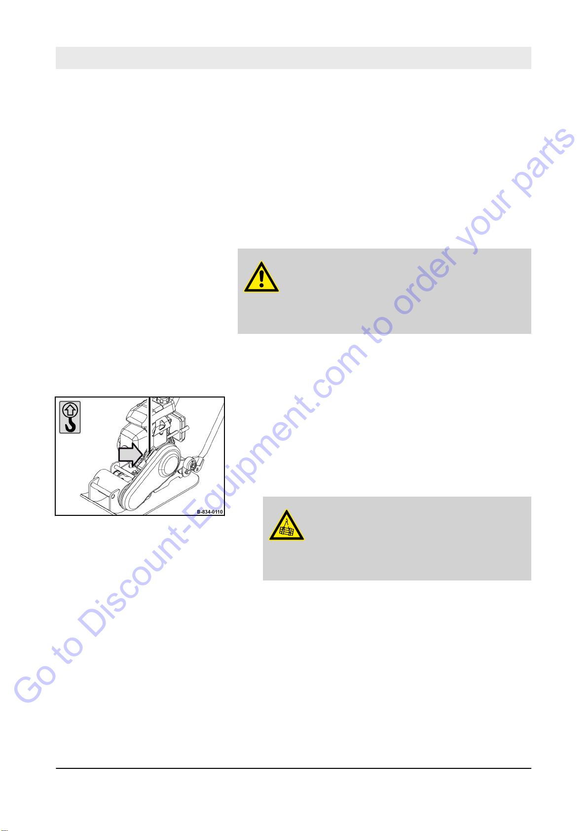
Loading / transporting the machine – Loading with lifting tackle
Go to Discount-Equipment.com to order your parts
7.2 Loading with lifting tackle
Use lifting tackle only in the prescribed direction of load application.
Lifting tackle must not be damaged by machine components.
Use only lifting tackle with suf
weight to be loaded. Minimum load bearing capacity of lifting
tackle: see operating weight
on page 11.
Protective equipment:
WARNING!
Danger of burning on hot components!
– Wear your personal protective equipment (pro-
tective gloves, protective clothing).
–
Avoid touching hot components.
ficient load bearing capacity for the
Ä
Chapter 2 ‘Technical data’
orking clothes
W
n
Protective gloves
n
Safety shoes
n
Fig. 72
1.
Park the machine in secured condition
‘Parking the machine in secured condition’ on page 74.
2. Let the machine and the engine cool down to ambient tem-
perature.
3. Check the lifting point including fastening elements for
damage before lifting the machine.
Do not use damaged or in any other way impaired lifting
ð
points.
4. Attach lifting tackle to the lifting point.
5. When lifting the machine, avoid uncontrolled movements of
the load. If necessary
6.
DANGER!
Danger to life caused by suspended
loads!
– Do not step or stand under suspended
Lift the machine carefully and set it down on the transport
vehicle.
, hold the load with guide ropes.
loads.
Ä
Chapter 6.6
79
BVP 10/30
Page 78
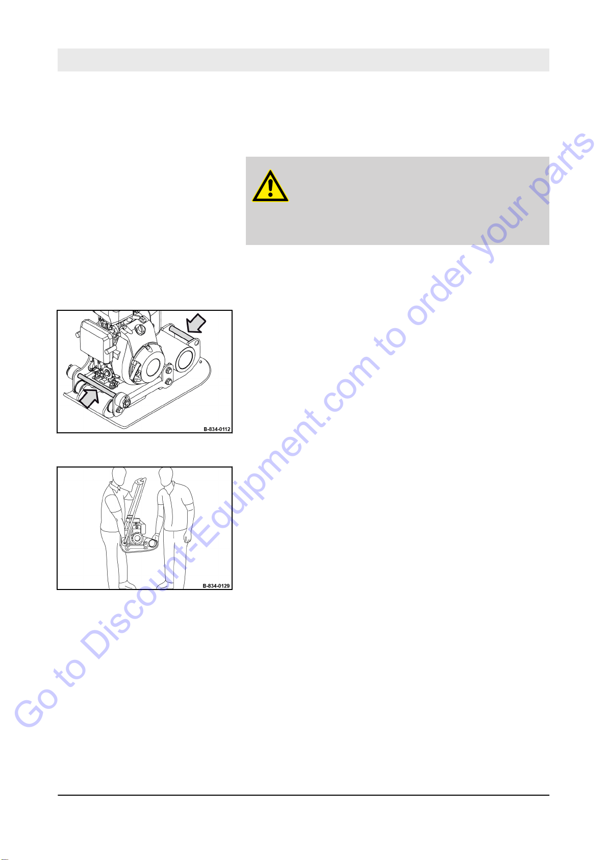
Loading / transporting the machine – Loading without lifting tackle
Go to Discount-Equipment.com to order your parts
7.3 Loading without lifting tackle
Protective equipment:
WARNING!
Danger of burning on hot components!
– Wear your personal protective equipment (pro-
tective gloves, protective clothing).
Avoid touching hot components.
–
1.
Park the machine in secured condition
‘Parking the machine in secured condition’ on page 74.
2. Let the machine and the engine cool down to ambient tem-
perature.
3. Check all lashing points including fastening elements for
damage before lifting the machine.
Do not use damaged or in any other way impaired
ð
lashing points.
Protective gloves
n
Safety shoes
n
Ä
Chapter 6.6
Fig. 73
Fig. 74
4. Lift the machine with the help of a second person by means
of the lashing points.
5. Hold the guide handle with one hand when lifting.
6. Set the machine down on the transport vehicle.
80
BVP 10/30
Page 79
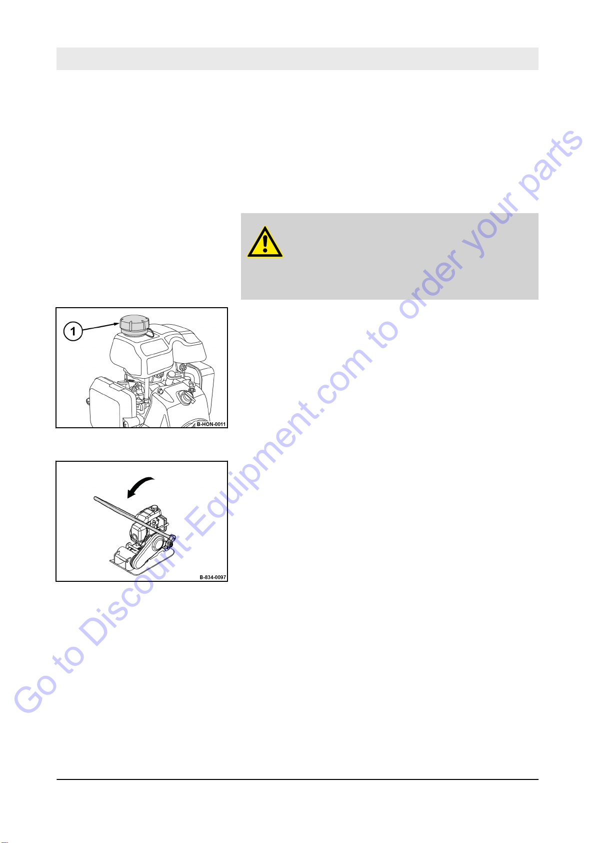
Loading / transporting the machine – Lashing the machine to the transport vehicle
Go to Discount-Equipment.com to order your parts
7.4 Lashing the machine to the transport vehicle
Use lashing gear only in the prescribed direction of load application.
Lashing gear must not be damaged by machine components.
Protective equipment:
WARNING!
Danger of burning on hot components!
– Wear your personal protective equipment (pro-
tective gloves, protective clothing).
Avoid touching hot components.
–
orking clothes
W
n
Protective gloves
n
Safety shoes
n
Fig. 75
Fig. 76
1. Close the cap of the fuel tank tightly
out during transport.
2. Fold down the guide handle into transport position.
, so that fuel cannot leak
81
BVP 10/30
Page 80
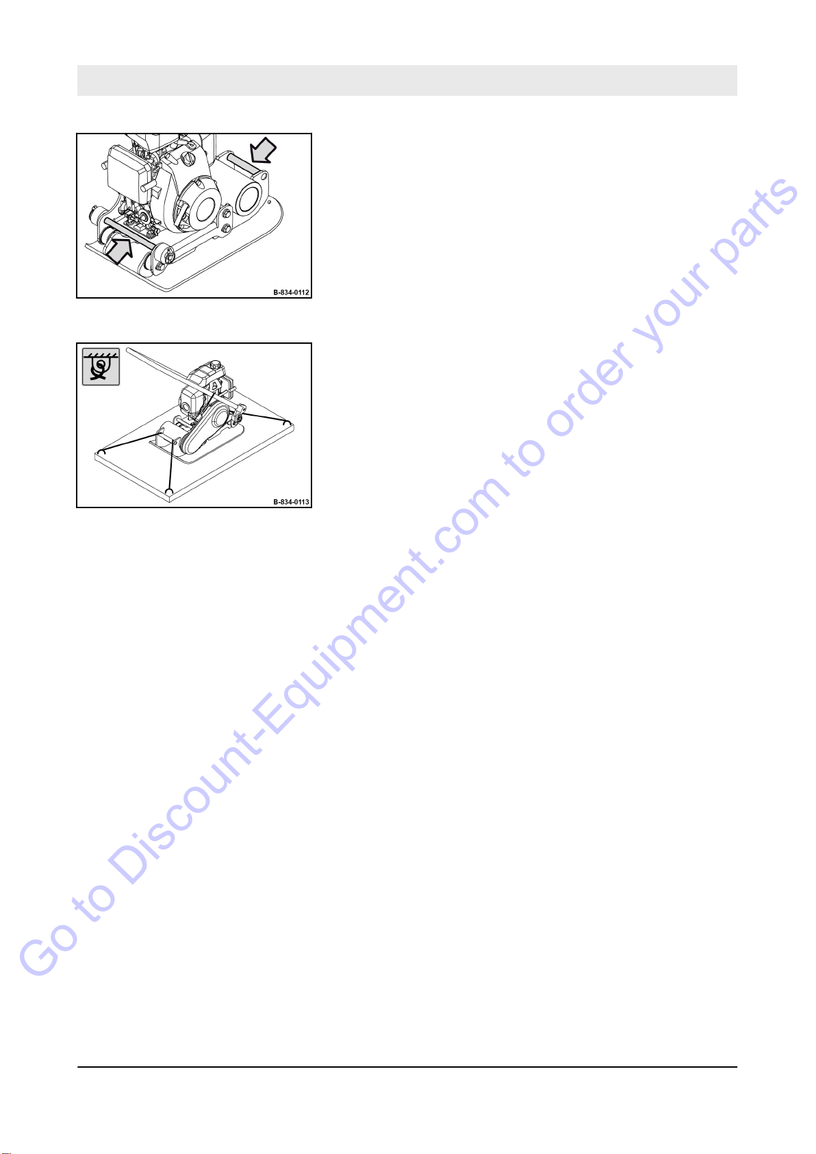
Loading / transporting the machine – Lashing the machine to the transport vehicle
Go to Discount-Equipment.com to order your parts
3. If necessary, pull the machine on an even surface by means
of the lashing points.
Fig. 77
4. Fasten four ratchet straps to the marked lashing points.
5. Lash the machine securely to the transport vehicle.
Fig. 78
82
BVP 10/30
Page 81
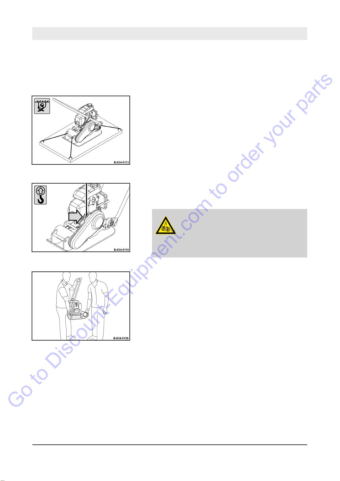
7.5 After transport
Go to Discount-Equipment.com to order your parts
Loading / transporting the machine – After transport
Fig. 79
Protective equipment:
1. Remove lashing gear
2. Attach lifting tackle to the lifting point.
3. When lifting the machine, avoid uncontrolled movements of
the load. If necessary
4.
DANGER!
Danger to life caused by suspended
loads!
– Do not step or stand under suspended
loads.
orking clothes
W
n
Protective gloves
n
Safety shoes
n
.
, hold the load with guide ropes.
Fig. 80
Fig. 81
Raise the machine carefully.
5. Alternatively, lift the machine with the help of a second
person by means of the lashing points.
Hold the guide handle with one hand when lifting.
6. Park the machine on level, firm ground.
7. Remove the lifting tackle.
83
BVP 10/30
Page 82

8 Maintenance
Go to Discount-Equipment.com to order your parts
Maintenance
85
BVP 10/30
Page 83
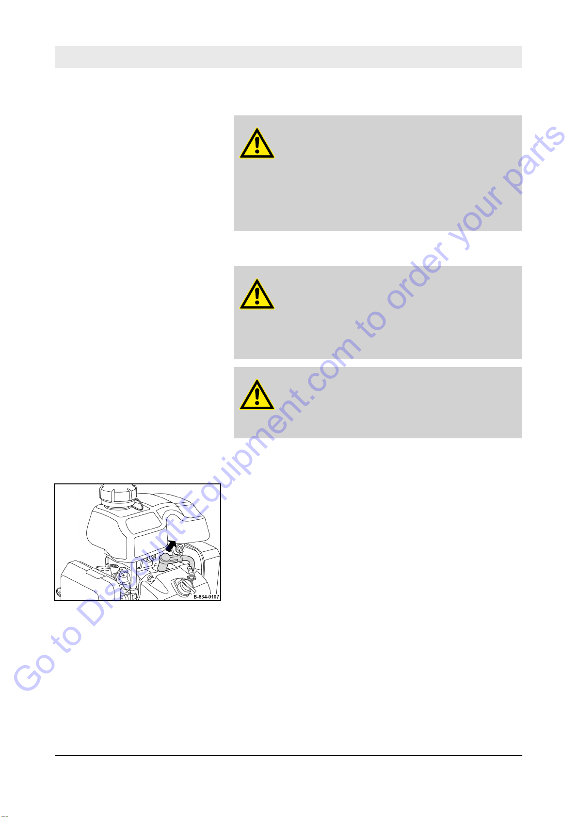
Maintenance – Preliminary remarks and safety notes
Go to Discount-Equipment.com to order your parts
8.1 Preliminary remarks and safety notes
DANGER!
Danger to life caused by an operationally
unsafe machine!
– The machine must only be serviced by quali-
fied and authorized personnel.
Follow the safety regulations for maintenance
–
Ä
work
on page 34.
Contact our customer service to carry out the required maintenance work.
WARNING!
Health hazard caused by fuels and lubricants!
– Safety regulations and environmental protec-
tion regulations must be followed when handling fuels and lubricants
dling fuels and lubricants’ on page 25.
Chapter 3.9 ‘Maintenance work’
Ä
Chapter 3.4 ‘Han-
Fig. 82
WARNING!
Danger of injury caused by rotating parts!
– Before starting work on the machine make sure
that the engine can not be started.
1. For all maintenance work park the machine in secured condi-
Ä
Chapter 6.6 ‘Parking the machine in secured condi-
tion
tion’ on page 74.
2. Pull of
3. Allow the machine to cool down.
4. Thoroughly clean the machine and engine before starting
5. After maintenance work has been completed, dispose of
6. After maintenance work is completed reinstall all protective
7. After all maintenance work is completed, plug the spark plug
f the spark plug socket.
maintenance work.
fuels and lubricants, filters, sealing elements and cleaning
cloths in line with environmental regulations.
devices.
socket back on.
86
BVP 10/30
Page 84

8.2 Fuels and lubricants
Go to Discount-Equipment.com to order your parts
Maintenance – Fuels and lubricants
8.2.1
8.2.1.1 Oil quality
8.2.1.2
Fig. 83
Engine oil
Oil viscosity
The following engine oil specifications are permitted:
n Engine oils for four-stroke engines acc. to API-classification SJ
or higher
Avoid mixing of engine oils.
Since engine oil changes its viscosity with the temperature, the
ambient temperature at the operating location of the engine is of
utmost importance when choosing the viscosity class (SAE-class).
The temperature data of the SAE-class always refers to fresh oils.
In travel operation engine oil ages because of soot and fuel residues. This adversely affects the properties of the engine oil, especially under low ambient temperatures.
SAE 10W-30 is recommended for general use.
You may alternatively use 15W-40 (except under low temperatures).
8.2.1.3 Oil change intervals
8.2.2 Fuel
8.2.2.1 Fuel quality
Oil change interval: semi-annually or every 100 operating hours.
Use unleaded gasoline with a research octane number of 91 or
higher (or octane number 86 or higher).
Use unleaded standard grade gasoline with maximum 10 percent
by volume of ethanol (E10) or maximum 5 percent by volume of
methanol.
Methanol must also contain co-solvents and corrosion inhibitors.
Do not use any fuel with a higher ethanol or methanol content.
The use of fuels with a higher ethanol or methanol content will
cause starting and/or power problems or even cause damage in
the fuel system.
87
BVP 10/30
Page 85

Maintenance – Fuels and lubricants
Go to Discount-Equipment.com to order your parts
8.2.2.2 Fuel stabilizer
If the machine is only occasionally used (if it is out of use for longer
than four weeks), mix in the correct amount of fuel stabilizer
directly after you have purchased fresh fuel.
The fuel stabilizer has a limited shelf life.
Please follow the instructions of the manufacturer concerning the
correct mixing ratio and shelf life.
Mixing in fuel stabilizer does not regenerate old fuel.
88
BVP 10/30
Page 86

8.3 List of fuels and lubricants
Go to Discount-Equipment.com to order your parts
Maintenance – List of fuels and lubricants
Assembly group Fuel or lubricant Spare parts
Summer Winter Observe the
Engine oil SAE 10W-30
Specification:
SAE 30
Fuel Gasoline (unleaded)
Specification:
Specification:
Ä
Chapter 8.2.1 ‘Engine oil’
on page 87
Ä
Chapter 8.2.2 ‘Fuel’
on page 87
Fuel stabilizer
Ä
Chapter 8.2.2.2 ‘Fuel stabil-
izer’ on page 88
number
0.4 l
0.8 l
009 940 20 as required
Filling quantity
level mark!
(0.1 gal us)
(0.2 gal us)
89
BVP 10/30
Page 87

Maintenance – Maintenance Table
Go to Discount-Equipment.com to order your parts
8.4 Maintenance Table
No. Maintenance works Page
Running-in instructions
8.5.1 General 91
8.5.2 After 25 operating hours 91
Monthly
8.6.1 Air filter maintenance 92
Semi-annually
8.7.1 Changing the engine oil 93
Annually
8.8.1 Checking, adjusting the valve clearance 94
8.8.2 Replacing the spark plug 98
8.8.3 Replacing the fuel strainer 99
8.8.4 Replacing the starter rope 100
8.8.5 Replacing the air filter 102
8.8.6 Replacing the V-belt 103
As required
8.9.1 Cleaning the cooling fins and the cooling air intake openings 106
8.9.2 Cleaning the machine 107
8.9.3 Cleaning, checking the spark plug, replacing if necessary 108
8.9.4 Checking, adjusting the engine speed 110
8.9.5 Measures for longer shut-down periods 112
90
BVP 10/30
Page 88

8.5 Running-in instructions
Go to Discount-Equipment.com to order your parts
Maintenance – Running-in instructions
8.5.1
General
8.5.2 After 25 operating hours
The following maintenance work must be performed when running
in new machines or overhauled engines.
Contact our customer service to carry out the required maintenance work.
1.
Change the engine oil
oil’ on page 93.
2. Check engine and machine for leaks.
3. Retighten the fastening screws on air filter
attachments.
4. Retighten the bolted connections on the machine.
5. Check the V
-belt.
Ä
Chapter 8.7.1 ‘Changing the engine
, exhaust and other
91
BVP 10/30
Page 89

B-541-0055
1
2
3
4
Maintenance – Monthly
Go to Discount-Equipment.com to order your parts
8.6 Monthly
8.6.1
Air filter maintenance
If the engine loses power or running characteristics
get worse, check the air filter and replace it if nec-
.
essary
NOTICE!
Danger of engine damage!
– Never start the engine after removing the air
filter.
– Do not let dirt drop into the air duct.
– Do not continue using a damaged or soiled air
filter. If in doubt use a new air filter.
– Replace the air filter after a year or 300 oper-
ating hours at the latest.
Protective equipment:
1.
Park the machine safely
in secured condition’ on page 74.
n
n
n
orking clothes
W
Safety shoes
Protective gloves
Ä
Chapter 6.6 ‘Parking the machine
Fig. 84
2. Let the machine and the engine cool down to ambient tem-
perature.
3. Unscrew fastening screws (4) and remove cover (3).
4. Remove the foam rubber insert (2) from the cover
5. T
6.
7. Replace damaged or soiled paper insert.
8. Clean the foam rubber insert in warm soapsuds, rinse and
9. Attach the foam rubber insert to the cover.
10. Fasten the paper insert and cover to the housing and tighten
ake the paper insert (1) out of the housing.
NOTICE!
Danger of engine damage!
– Ensure that no dirt falls into the air duct.
Wipe the inside of the housing only with a lint-free, clean
cloth.
dry thoroughly.
Do not apply any oil to the foam rubber insert.
the fastening screws, tightening torque: 2.3 Nm (1.7 ft·lbf).
.
92
BVP 10/30
Page 90
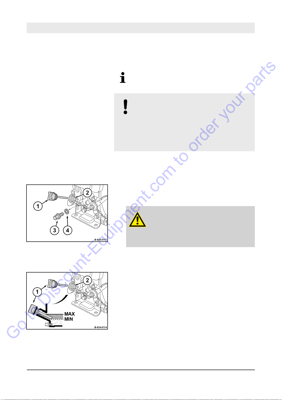
8.7 Semi-annually
Go to Discount-Equipment.com to order your parts
Maintenance – Semi-annually
8.7.1
Changing the engine oil
Perform this maintenance work at the latest after
100 operating hours
NOTICE!
Danger of engine damage!
– Change the oil only with the engine at oper-
ating temperature.
Use only oil of the permitted specification
–
Ä
Chapter 8.2.1 ‘Engine oil’ on page 87.
Ä
– Filling quantity:
lubricants’ on page 89
Protective equipment:
1.
Park the machine in secured condition
‘Parking the machine in secured condition’ on page 74.
2. Clean the area around the filler opening (2) and drain plug
(3).
3. Unscrew the oil dipstick (1).
4.
WARNING!
Danger of burning on hot components!
– Wear your personal protective equipment
–
n
n
(protective gloves, protective clothing).
Avoid touching hot components.
Chapter 8.3 ‘List of fuels and
orking clothes
W
Protective gloves
Ä
Chapter 6.6
Fig. 85
Fig. 86
Unscrew the drain plug and catch any oil running out.
5. Clean the oil drain plug and screw it back in with a new seal
ring (4).
6. Fill in fresh oil up to the bottom edge of the filler opening (2).
7. Screw the oil dipstick (1) in.
8. Check for leaks after a short test run.
9. Check the oil level on the dipstick, correct if necessary
10. Dispose of oil in an environmentally friendly way
93
BVP 10/30
.
.
Page 91

Maintenance – Annually
Go to Discount-Equipment.com to order your parts
8.8 Annually
8.8.1
Checking, adjusting the valve clearance
Perform this maintenance work at the latest after
200 operating hours.
NOTICE!
Danger of engine damage!
e recommend to have this work carried out by
W
trained personnel or our after sales service.
– Before checking the valve clearance let the
engine cool down.
Valve clearance:
Intake valve (IN) 0.15 mm (0.006 in)
Exhaust valve (EX) 0.20 mm (0.008 in)
Protective equipment:
W
orking clothes
n
Protective gloves
n
Preparations
1.
Park the machine in secured condition
‘Parking the machine in secured condition’ on page 74.
2. Let the machine and the engine cool down to ambient tem-
perature.
3. Drain the fuel.
Ä
Chapter 6.6
94
BVP 10/30
Page 92
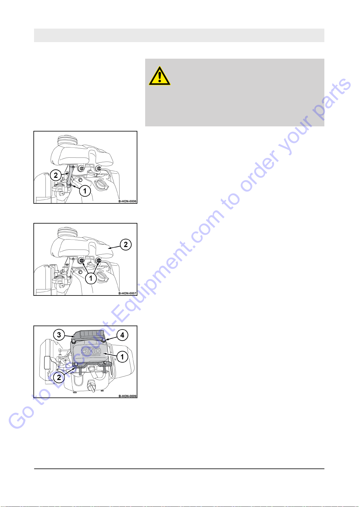
Removing the fuel tank
Go to Discount-Equipment.com to order your parts
Maintenance – Annually
WARNING!
Health hazard caused by contact with gasoline!
– Wear your personal protective outfit (protective
gloves, protective clothing).
–
Do not inhale any fuel fumes.
– Do not swallow gasoline.
– Avoid contact with gasoline.
Fig. 87
Fig. 88
4. Loosen the hose clamp (1) and pull of
5. Unscrew two fastening nuts (1) and remove the fuel tank (2).
f the fuel hose (2).
Removing the valve cover
Fig. 89
6. Remove four fastening screws (4).
7. Remove valve cover (1) and holding fixtures (2, 3).
95
BVP 10/30
Page 93
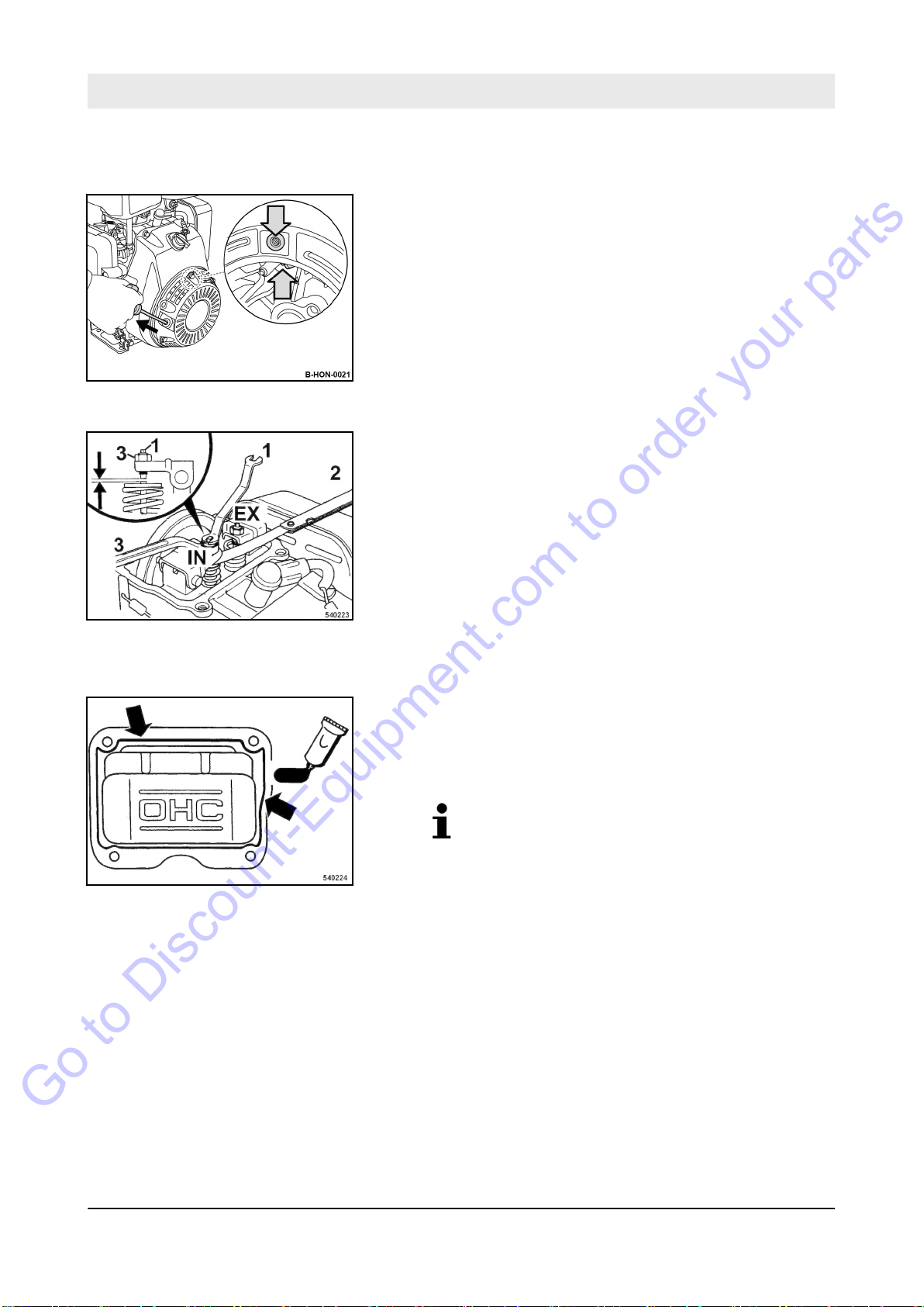
Maintenance – Annually
Go to Discount-Equipment.com to order your parts
Checking, adjusting the valve clearance
Fig. 90
8. Close valves:
For this slowly pull the starter handle, until resistance can be
felt and the notch on the flywheel is aligned with the bore on
the top side of the fan cover.
9. Slowly guide the starter handle back.
10. Check the valve clearance on the intake valve (IN) with a
feeler gauge (2).
11. T
o adjust the valve hold the adjustment screw (1) and loosen
locking nut (3).
Adjust the valve clearance with the adjustment screw.
Retighten the locking nut, tightening torque: 8 Nm (6 ft·lbf).
Fig. 91
Installing the valve cover
Fig. 92
12. Check the valve clearance on the exhaust valve (EX).
13. Clean the sealing surfaces of valve cover and cylinder block.
14. Apply a bead of liquid sealant of approx.
(0.06 to 0.08 in) in diameter to the inner side of the cylinder
head cover.
Liquid sealant: Three Bond 1207B or similar.
1.5 to 2.0 mm
96
BVP 10/30
Page 94
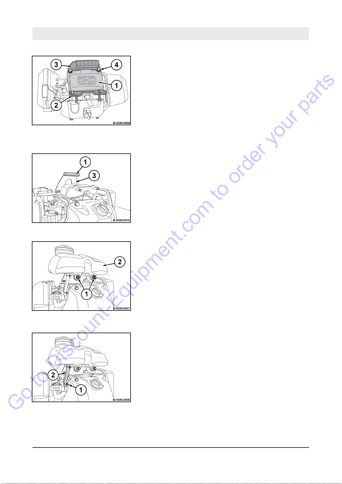
Fig. 93
Go to Discount-Equipment.com to order your parts
Installing the fuel tank
Maintenance – Annually
15. Attach the valve cover (1) to the cylinder block within the next
10 minutes.
16. Fasten the valve cover and holding fixture (2, 3) with four fas-
tening screws (4).
17. Attach the rubber (1) to the holding fixture (3).
Fig. 94
Fig. 95
18. Attach the fuel tank (2) and secure it with fastening nuts (1).
19. Fasten the fuel hose (2) with the hose clamp (1).
Fig. 96
Final work
20. W
ait another 20 minutes before starting the engine.
97
BVP 10/30
Page 95
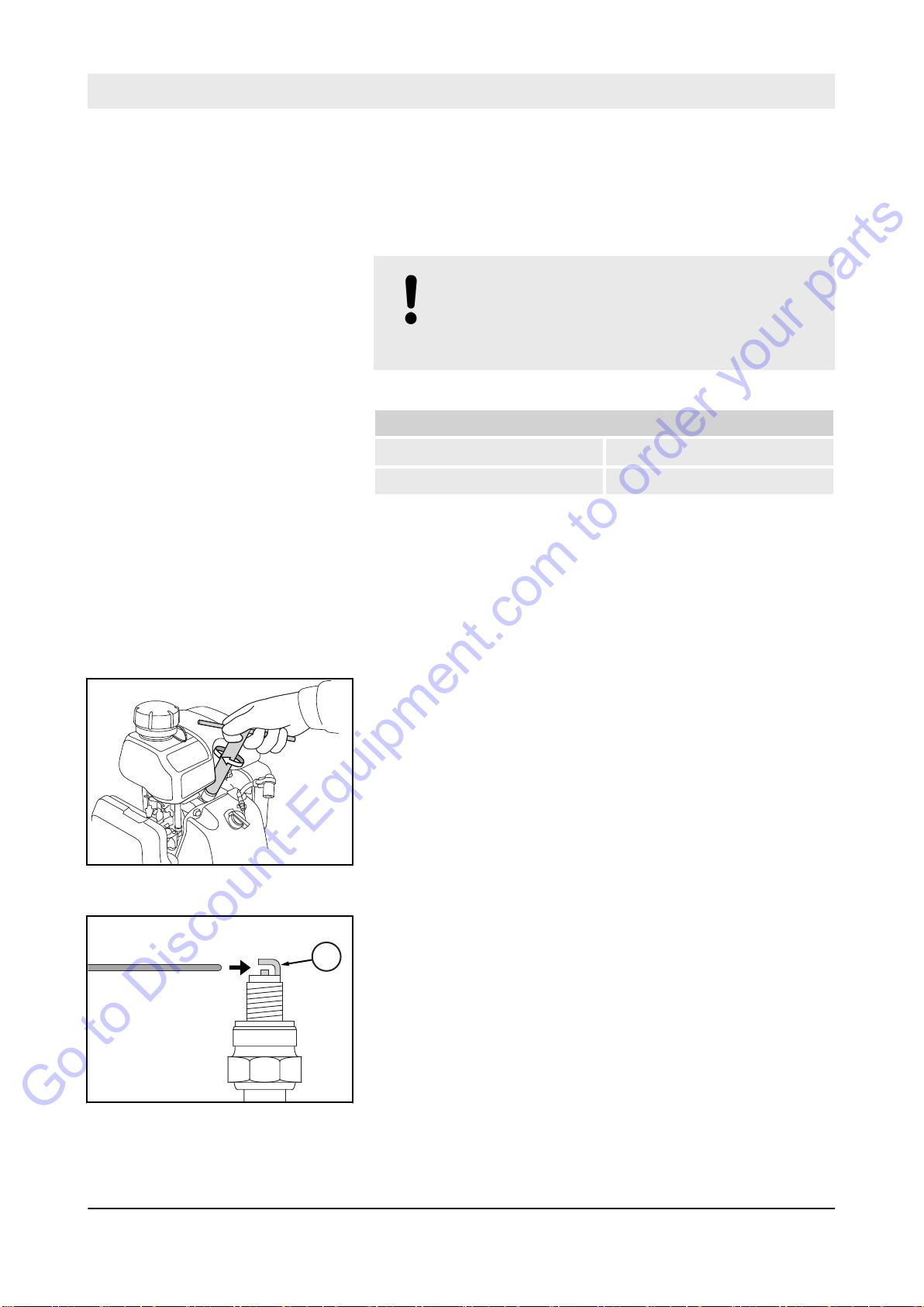
B-HON-0029
1
B-HON-0031
Maintenance – Annually
Go to Discount-Equipment.com to order your parts
8.8.2 Replacing the spark plug
21. After a short test run check the engine for leaks.
NOTICE!
Danger of engine damage!
– Do not use spark plugs with incorrect heat
value.
Recommended spark plugs:
NGK CR5HSB
DENSO U16FSR-UB
Fig. 97
Protective equipment:
Special tool:
1.
Park the machine safely Ä Chapter 6.6 ‘Parking the machine
in secured condition’ on page 74.
2. Let the engine cool down to ambient temperature.
3. Clean the area around the spark plug.
4. Remove the spark plug using the spark plug spanner.
5. Check the electrode gap of the new spark plug with a feeler
gauge, if necessary
Nominal value: 0.6 - 0.7 mm (0.024 - 0.028 in)
ð
Working clothes
n
Safety shoes
n
Protective gloves
n
16 mm spark plug spanner
n
, adjust the gap.
6. T
7. Carefully screw in the spark plug by hand.
8. Once the sealing ring of the new spark plug is in contact,
Fig. 98
o set the electrode distance carefully bend the electrode (1).
tighten for another
1/2 turn with the spark plug spanner.
98
BVP 10/30
Page 96
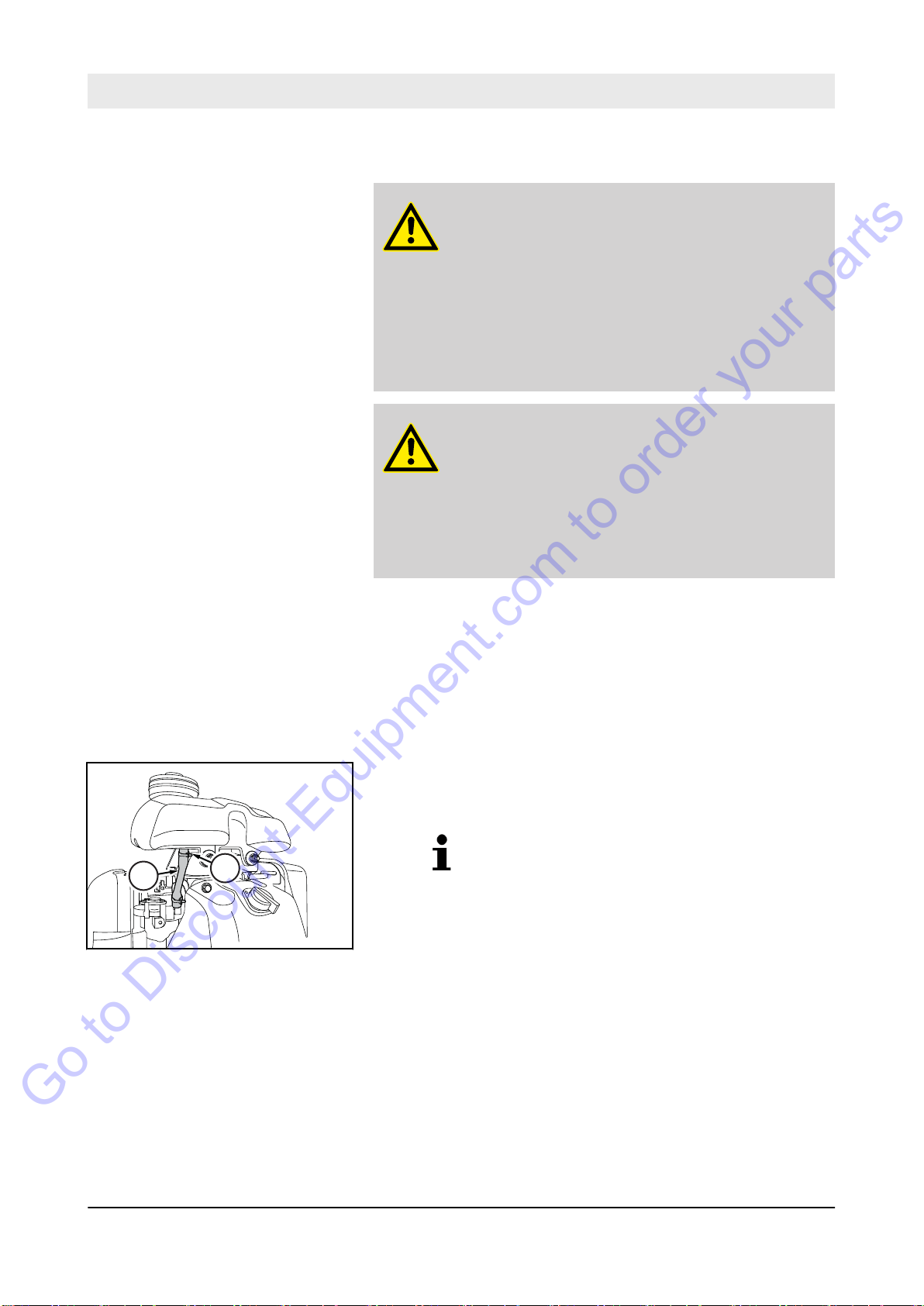
8.8.3 Replacing the fuel strainer
1
2
B-HON-0012
Go to Discount-Equipment.com to order your parts
Maintenance – Annually
DANGER!
Danger to life caused by explosive gas-air
mixes!
– Do not allow gasoline to come into contact with
hot components.
–
Smoking and open fire is prohibited.
– Keep away from heat sources, sparks and
other sources of ignition.
– Do not spill any gasoline.
WARNING!
Health hazard caused by contact with gasoline!
– Wear your personal protective outfit (protective
gloves, protective clothing).
Do not inhale any fuel fumes.
–
– Do not swallow gasoline.
– Avoid contact with gasoline.
Fig. 99
Protective equipment:
1.
Park the machine safely
in secured condition’ on page 74.
2. Allow the engine to cool down.
3. Drain the fuel.
4. Loosen the hose clamp (1) and pull of
5.
The fuel strainer is located in the fuel hose.
When pulling off the fuel hose, the fuel
strainer is also pulled out of the fuel tank.
orking clothes
W
n
Safety shoes
n
Protective gloves
n
Ä
Chapter 6.6 ‘Parking the machine
f the fuel hose (2).
99
BVP 10/30
Page 97
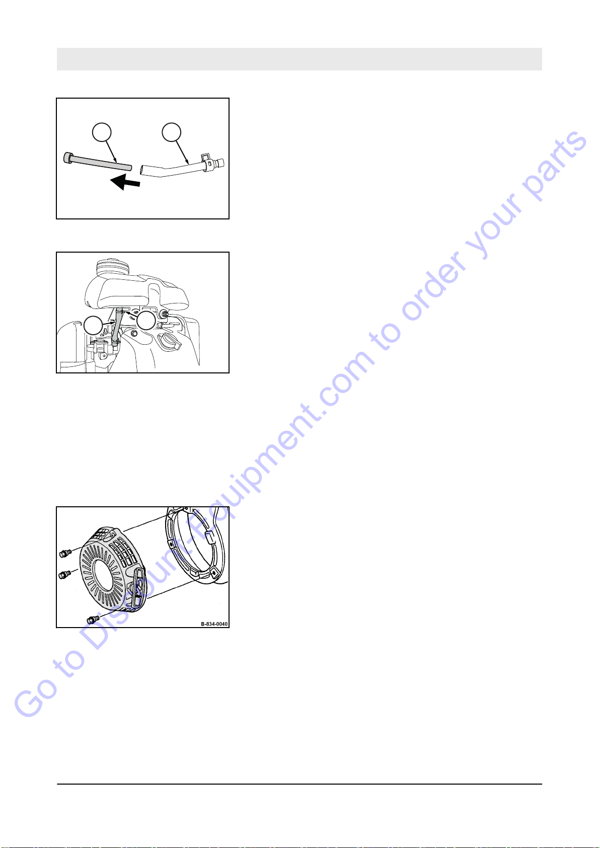
1
2
B-HON-0013
1
2
B-HON-0012
Maintenance – Annually
Go to Discount-Equipment.com to order your parts
Fig. 100
6. Pull the fuel strainer (1) out of the fuel hose (2) and replace it.
7. Insert the fuel strainer back into the fuel hose.
8. Attach the fuel hose (2) and secure it with a hose clamp (1).
9. Fill in fuel.
Fig. 101
8.8.4
Fig. 102
Replacing the starter rope
Protective equipment:
1.
Park the machine in secured condition
‘Parking the machine in secured condition’ on page 74.
2. Allow the engine to cool down.
3. Disassembling the recoil starter
orking clothes
W
n
Protective gloves
n
Ä
Chapter 6.6
.
100
BVP 10/30
Page 98
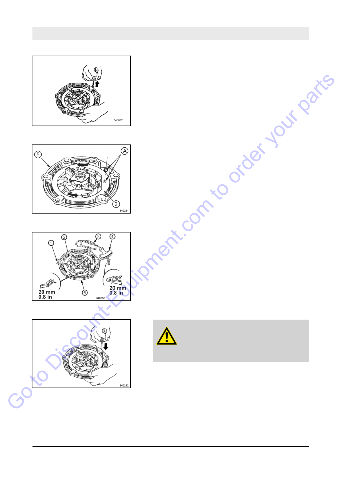
Fig. 103
Go to Discount-Equipment.com to order your parts
Maintenance – Annually
4. Pull the starter rope with the starter handle out completely.
5. If the starter rope has been torn or the coil has recoiled com-
pletely:
n Before assembling the rope, turn the coil (2) 5 revolutions
in anti-clockwise direction and align the rope openings in
coil and housing (5) to one another (A).
Fig. 104
Fig. 105
Fig. 106
6. Secure the coil against winding up. For this purpose tie the
coil (2) to the housing (5) with a cable strap (1).
7. Untie the knots of the starter rope at both ends and remove
the old starter rope.
8. Thread in the new starter rope (3) and fix it with knots on
both ends.
9.
CAUTION!
Danger of injury caused by the starter
handle hitting against your body!
– Do not let the starter handle hit back.
Remove the fixing of the coil and run the starter handle
slowly back to initial position.
10. Pull the starter handle to check the function and light move-
ment of the recoil starter
.
101
BVP 10/30
Page 99
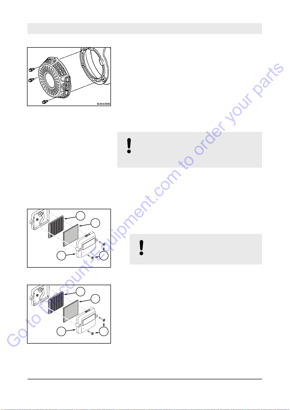
B-541-0055
1
2
3
4
B-541-0055
1
2
3
4
Maintenance – Annually
Go to Discount-Equipment.com to order your parts
Fig. 107
8.8.5 Replacing the air filter
11. Assemble the recoil starter.
NOTICE!
Danger of engine damage!
– Do not start the engine after having removed
the air filter
.
Fig. 108
Protective equipment:
1.
Park the machine safely
in secured condition’ on page 74.
2. Unscrew fastening screws (4) and remove cover (3).
3. Remove the foam rubber insert (2) from the cover
4. T
5.
6. Replace paper element and foam element.
7. Attach the foam rubber insert (2) to the cover (3).
8. Fasten the paper insert (1) and cover to the housing and
ake the paper insert (1) out of the housing.
NOTICE!
Danger of engine damage!
– Ensure that no dirt falls into the air duct.
Wipe the inside of the air filter housing with a clean cloth.
tighten the fastening screws (4), tightening torque:
2.3 Nm (1.7 ft·lbf).
orking clothes
W
n
Safety shoes
n
Protective gloves
n
Ä
Chapter 6.6 ‘Parking the machine
.
Fig. 109
102
BVP 10/30
Page 100

8.8.6 Replacing the V-belt
21
B-834-0137
31 2
B-834-0139
31
B-834-0140
Go to Discount-Equipment.com to order your parts
Maintenance – Annually
Fig. 110
Protective equipment:
1.
Park the machine safely
in secured condition’ on page 74.
2. Let the machine and the engine cool down to ambient tem-
perature.
3. Unscrew the fastening screws (2) and remove the V
guard (1).
4. Loosen the fastening screws (3) on both sides.
5. Pull the engine carrier (1) forward, remove and replace the V
belt (2).
orking clothes
W
n
Safety shoes
n
Protective gloves
n
Ä
Chapter 6.6 ‘Parking the machine
-belt
-
Fig. 111
Fig. 112
6. Install the new V
7. T
ighten the fastening screws (3) on both sides.
103
BVP 10/30
-belt and pull the engine carrier back.
 Loading...