

Page 1
Operating instructions
Maintenance instructions
Original operating instructions
12/2012
Catalogue No.
008 051 21
BPR 45/55 D - BPR 55/65 D
S/N 101 692 14 .... / S/N 101 692 33 .... / S/N 101 692 16 .... / S/N 101 692 34 ....
Reversible Vibrating Plate
Page 2
Page 3

Foreword
BOMAG 3BPR 45/55 D, BPR 55/65 D
1 Foreword
BOMAG manufactures machine for earth, asphalt and refuse compaction, stabilizers/recyclers as well as milling machine and finishers.
BOMAG’s vast experience in connection with
state-of-the-art production and testing methods, such as lifetime tests of all important
components and highest quality demands
guarantee maximum reliability of your machine.
This manual comprises:
l Safety regulations
l Operating instructions
l maintenance instructions
l Trouble shooting
Using these instructions will
l help you to become familiar with the machine.
l avoid malfunctions caused by unprofessional
operation.
Compliance with the maintenance instructions will
l enhance the reliability of the machine on con-
struction sites,
l prolong the lifetime of the machine,
l reduce repair costs and downtimes.
BOMAG will not assume liability for the function of
the machine
l if it is handled in a way not complying with the
usual modes of use,
l if it is used for purposes other than those men-
tioned in these instructions.
No warranty claims can be lodged in case of damage resulting from
l operating errors,
l insufficient maintenance and
l wrong fuels and lubricants.
Please note!
This manual was written for operators and maintenance personnel on construction sites.
These operating and maintenance instructions are
part of the machine.
You should only operate the machine after you
have been instructed and in compliance with these
instructions.
Strictly observe the safety regulations.
Please observe also the guidelines of the Civil Engineering Liability Association ”Safety Rules for
the Operation of Road Rollers and Soil Compactors” and all relevant accident prevention regulations.
For your own personal safety you should only
use original spare parts from BOMAG.
For your machine BOMAG offers service kits
to make maintenance easier.
In the course of technical development we reserve the right for technical modifications
without prior notification.
These operating and maintenance instructions are
also available in other languages.
Apart from that, the spare parts catalogue is available from your BOMAG dealer against the serial
number of your machine.
Your BOMAG dealer will also supply you with information about the correct use of our machines in
soil and asphalt construction.
The above notes do not constitute an extension of
the warranty and liability conditions specified in the
general terms of business of BOMAG.
We wish you successful work with your BOMAG
machine.
BOMAG GmbH
Copyright by BOMAG
Page 4
Foreword
BOMAG4 BPR 45/55 D, BPR 55/65 D
Please fill in
. . . . . . . . . . . . . . . . . . . . . . . . . . . .
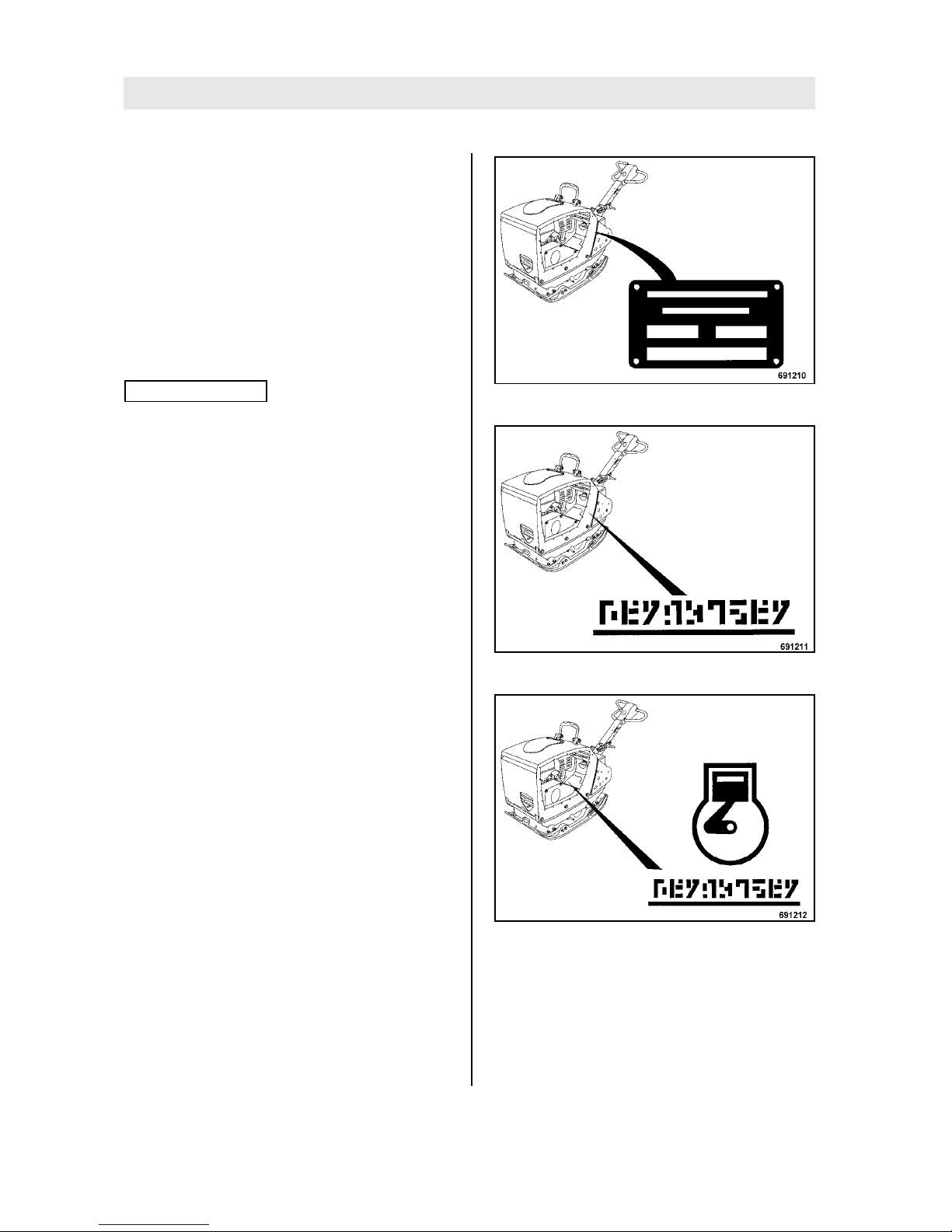
Machine type (Fig. 1)
. . . . . . . . . . . . . . . . . . . . . . . . . . . .
Serial-number (Fig. 1 and 2)
. . . . . . . . . . . . . . . . . . . . . . . . . . . .
Engine type (Fig. 3)
. . . . . . . . . . . . . . . . . . . . . . . . . . . .
Engine number (Fig. 3)
Note
i
Supplement the above data together with the commissioning protocol.
During commissioning our organisation will instruct you in the operation and maintenance of the
machine.
Please observe strictly the safety regulations and
all notes on risks and dangers!
Fig. 1
Fig. 2
Fig. 3
Page 5

Table of Contents
BOMAG 5BPR 45/55 D, BPR 55/65 D
1Foreword 3
2 Technical Data 7
3 Safety regulations 13
4 Indicators and Controls 19
4.1 General notes 20
4.2 Description of indicators and control elements 20
4.3 Function of the Economizer 22
5 Operation 23
5.1 General 24
5.2 Tests before taking into operation 24
5.3 Folding down the steering rod 25
5.4 Starting the engine electrically 25
5.5 Starting with recoil starter 27
5.6 Operation of Economizer 29
5.7 Work/operation 30
5.8 Shutting down the engine 32
5.9 Loading/transport 33
6 Maintenance 35
6.1 General notes on maintenance 36
6.2 Fuels and lubricants 37
6.3 Table of fuels and lubricants 39
6.4 Running-in instructions 40
6.5 Maintenance table 41
Maintenance every day 43
6.6 Clean the machine 43
6.7 Check the engine oil level 43
6.8 Check the fuel level 44
6.9 Check, clean the air filter, replace if necessary 45
Maintenance every month 47
6.10 Clean the cooling fins and the cooling air intake openings 47
6.11 Drain the sludge from the fuel tank 48
Maintenance every 6 months 49
6.12 Check the battery condition, grease the poles 49
6.13 Check the oil level in the exciter housing 50
6.14 Check the V-belt tension, if necessary replace the V-belt 50
Maintenance every year 53
6.15 Change engine oil and oil filter 53
Page 6

Table of Contents
BOMAG6 BPR 45/55 D, BPR 55/65 D
6.16 Replacing the fuel filter 54
6.17 Change the oil in the exciter housing 55
6.18 Check the hydraulic oil level 56
6.19 Check the rubber buffers 58
As required 59
6.20 Tightening the screws 59
6.21 Engine conservation 59
7 Trouble shooting 61
7.1 General notes 62
7.2 Starting with jump wires 62
7.3 Fuses 63
7.4 Engine problems 64
7.5 Trouble shooting Economizer 66
8Disposal 67
8.1 Final shut-down of machine 68
Page 7

BOMAG 7BPR 45/55 D, BPR 55/65 D
2 Technical Data
Page 8
Technical Data
BOMAG8 BPR 45/55 D, BPR 55/65 D
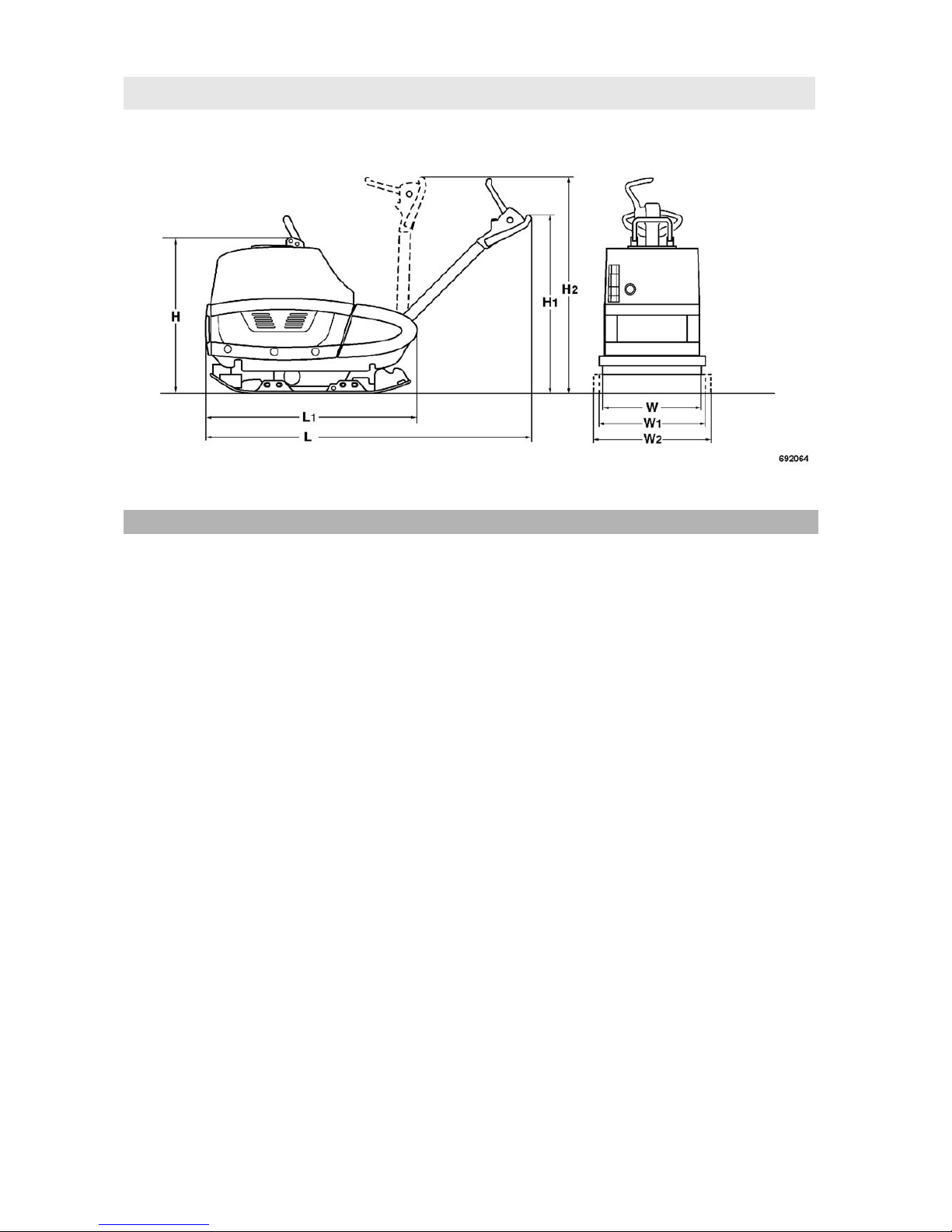
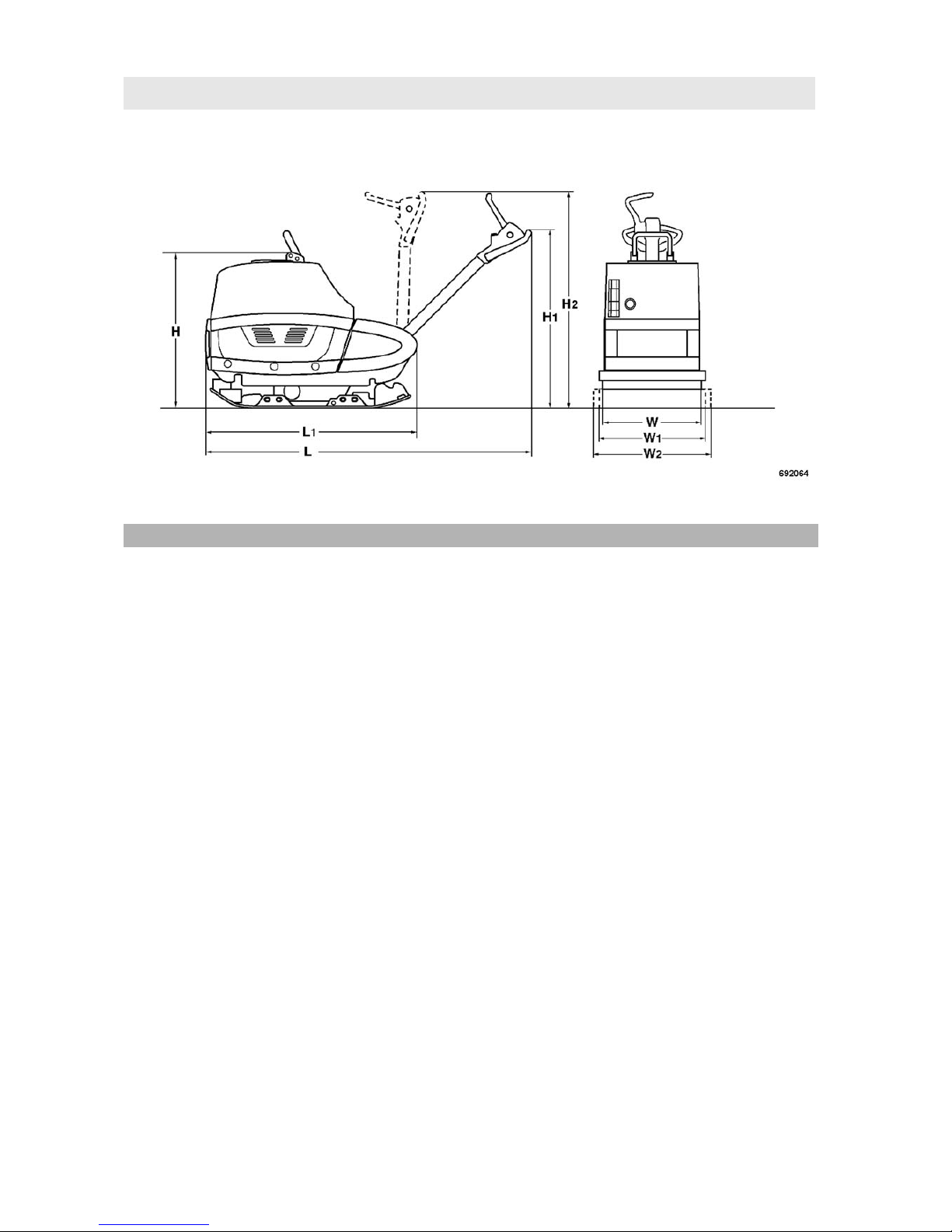
Fig. 4
BPR 45/55 D H H1 H2 L L1 W W1 W2
Dimensions in
mm
790 980 1350 1700 900 450 550 750
Dimensions in
inch
31.1 38.6 53.2 66.9 35.4 17.7 21.7 29.5
BPR 45/55 D
Weights
Operating weight (CECE) (W) 381 kg 840 lbs
Operating weight (CECE) (W1) 396 kg 873 lbs
Operating weight (CECE) (W2) 412 kg 908 lbs
Basic weight 391 kg 862 lbs
Economizer
1
+ 5 kg 11 lbs
Travel characteristics
Working speed max. 28 m/min 92 ft/min
Max. gradability (depending on soil) 35% 35%
Drive
Engine manufacturer Lombardini Lombardini
Type 15 LD 440 15 LD 440
Cooling Air Air
Number of cylinders 1 1
Page 9

Technical Data
BOMAG 9BPR 45/55 D, BPR 55/65 D
Note
i
Subject to technical alterations.
Rated power ISO 9249 6.6 KW 8.9 hp
Rated speed 3000 min
-1
3000 rpm
Drive system mechanical mechanical
Exciter system
Frequency 70 Hz 4200 vpm
Centrifugal force 45 kN 10116 lbf
Filling capacities
Fuel (diesel) 5.0 l 1.3 gal us
Engine oil 1.5 l 0.4 gal us
1 Optional equipment
BPR 45/55 D
Page 10
Technical Data
BOMAG10 BPR 45/55 D, BPR 55/65 D
Fig. 5
BPR 55/65 D H H1 H2 L L1 W W1 W2
Dimensions in
mm
790 980 1350 1700 900 450 650 750
Dimensions in
inch
31.1 38.6 53.2 66.9 35.4 17.7 25.6 29.5
BPR 55/65 D
Weights
Operating weight (CECE) (W) 436 kg 961 lbs
Operating weight (CECE) (W1) 456 kg 1005 lbs
Operating weight (CECE) (W2) 467 kg 1030 lbs
Basic weight 451 kg 994 lbs
Economizer
1
+ 5 kg 11 lbs
Travel characteristics
Working speed max. 28 m/min 92 ft/min
Max. gradability (depending on soil) 35% 35%
Drive
Engine manufacturer Lombardini Lombardini
Type 15 LD 440 15 LD 440
Cooling Air Air
Number of cylinders 1 1
Page 11

Technical Data
BOMAG 11BPR 45/55 D, BPR 55/65 D
Note
i
Subject to technical alterations.
Rated power ISO 9249 6.6 KW 8.9 hp
Rated speed 3000 min
-1
3000 rpm
Drive system mechanical mechanical
Exciter system
Frequency 66 Hz 3960 vpm
Centrifugal force 55 kN 12365 lbf
Filling capacities
Fuel (diesel) 5.0 l 1.3 gal us
Engine oil 1.5 l 0.4 gal us
1 Optional equipment
BPR 55/65 D
Page 12

Technical Data
BOMAG12 BPR 45/55 D, BPR 55/65 D
The following noise and vibration data acc. to
- EC Machine Regulation edition 2006/42/EC
- the noise regulation 2000/14/EG, noise protection guideline 2003/10/EC
- Vibration Protection Regulation 2002/44/EC
were determined during conditions typical for this type of equipment and by application of harmonized standards.
During operation these values may vary because of the existing operating conditions.
Noise value
Sound pressure level on the place of the operator:
BPR 45/55 D: L
pA
= 95 dB(A), determined acc. to ISO 11204 and EN 500
BPR 55/65 D: L
pA
= 95 dB(A), determined acc. to ISO 11204 and EN 500
Guaranteed sound power level:
BPR 45/55 D: L
WA
= 108 dB(A), determined acc. to ISO 3744 and EN 500
BPR 55/65 D: L
WA
= 108 dB(A), determined acc. to ISO 3744 and EN 500
Danger
!
Loss of hearing!
Wear your personal noise protection means (ear defenders) before starting operation.
Vibration value
Hand-arm vibration:
Vector total of the weighted effective acceleration in three orthogonal directions:
Weighted total vibration value
BPR 45/55 D: a
hv
= 4,6 m/s2, on crushed rock determined acc. to ISO 5349 and EN 500
BPR 55/65 D: a
hv
= 8,7 m/s2, on crushed rock determined acc. to ISO 5349 and EN 500
Caution
!
Observe the daily vibration load (Industrial safety acc. to 2002/44/EEC).
Page 13

BOMAG 13BPR 45/55 D, BPR 55/65 D
3 Safety regulations
Page 14

Safety regulations
BOMAG14 BPR 45/55 D, BPR 55/65 D
General
This BOMAG machine has been built in compliance with the latest technical standard and
complies with the applicable regulations and
technical rules. However, dangers for persons
and property may arise from this machine, if:
l it is used for purposes other than the ones it is
intended for,
l it is operated by untrained personnel,
l it is changed or converted in an unprofessional
way,
l the safety instructions are not observed.
Each person involved in the operation, maintenance and repair of the machine must therefore read and comply with these safety
regulations. If necessary, this must be confirmed by obtaining the signature of the customer.
Furthermore, the following obviously also applies:
l applicable accident prevention instructions,
l generally accepted safety and road traffic reg-
ulations,
l country specific safety regulations. It is the
duty of the operator to be acquainted with
these instructions and to apply these accordingly. This applies also for local regulations
concerning different types of handling work.
Should the recommendations in these instructions be different from the regulations valid in
your country, you must comply with the safety
regulations valid in your country.
Intended use
This machine must only be used for:
l Compaction of all types of soils
l Repair work on all types of soil
l Paving of walkways
l Work in trenches
l Underfilling and compaction of hard shoulders
Unintended use
Dangers may arise from the machine when it is
used for purposes other than the one it is intended
for.
Any danger caused by intended use is the sole responsibility of the customer or driver/operator, the
manufacturer cannot be made liable.
Examples for unintended use are:
l Dragging the machine along as a measure of
transportation
l Throwing the machine off the transport vehicle
l Attaching an additional weight to the machine
It is not permitted to stand on the machine while
working.
Any transport ropes fastened to the machine must
be removed before operation.
Starting and operation of the machine in explosive
environments and in underground mining is prohibited.
Remaining dangers, remaining risks
Despite careful work and compliance with standards and regulations it cannot be ruled out that further dangers may arise when working with and
handling the machine.
Both the machine as well as all other system components comply with the currently valid safety regulations. Nevertheless, remaining risks cannot be
ruled out completely, even when using the machine for the purpose it is intended for and following all information given in the operating
instructions.
A remaining risk can also not be excluded beyond
the actual danger zone of the machine. Persons
remaining in this area must pay particular attention
to the machine, so that they can react immediately
in case of a possible malfunction, an incident or
failure etc.
All persons remaining ion the area of the machine
must be informed about the dangers that arise
from the operation of the machine.
Regular safety inspections
Have the machine inspected by an expert (capable person) as required for the conditiosn the machine is working under, but at least once every
year.
Page 15

Safety regulations
BOMAG 15BPR 45/55 D, BPR 55/65 D
Who is allowed to operate the machine?
Only trained, instructed and authorized persons of
at least 18 years of age are permitted to drive and
operate this machine. For operation of the machine the responsibilities must be clearly specified
and complied with.
Persons under the influence of alcohol, medicine
or drugs are not allowed to operate, service or repair the machine.
Maintenance and repair work requires specific
knowledge and must therefore only be performed
by trained specialists.
Changes and conversions to the machine
Unauthorized changes to the machine are prohibited for safety reasons.
Original parts and accessories have been specially designed for this machine.
We wish to make explicitly clear that we have not
tested or approved any parts or accessories not
supplied by us.
The installation and/or use of such products may
have an adverse effect on the active and/or passive safety.
The manufacturer explicitly excludes any liability
for damage caused by the use of non-original
parts or accessories.
Damage, deficiencies, misuse of safety
installations
Machines which are not safe to operate must be
immediately taken out of service and shall not be
used, until these deficiencies have been properly
rectified.
Safety installations and switches must neither be
removed nor must they be made ineffective.
Notes on safety in the operating and
maintenance instructions
Danger!
Paragraphs marked like this highlight possible
dangers for persons.
Caution
!
Paragraphs marked like this highlight possible
dangers for machines or parts of the machine.
Note
i
Paragraphs marked like this contain technical information for the optimal economical use of the
machine.
Environment
Paragraphs marked like this point out practices for safe and environmental disposal of fuels
and lubricants as well as replacement parts.
Observe the regulations for the protection of
the environment.
Loading/transporting the machine
Make sure that persons are not endangered by the
machine tipping or sliding off.
Use only safe lifting gear of sufficient load bearing
capacity Minimum lifting capacity of lifting gear:
see operating weight in chapter "Technical Data".
Loads must only be attached and hoisted by an
expert (capable person).
Fasten the lifting gear only at the specified lifting
points.
Check lifting eye for damage before use. Do not
use a damaged or in any other way impaired lifting
eye.
Do not lift or lower the machine jerkily.
The tension must always be effective in vertical direction.
The machine must not swing about when being lifted.
Do not step or stand under suspended loads.
Always use suitable lashing gear on the lifting
points to lash down the machine.
Lash the machine down, so that it is secured
against rolling, sliding and turning over.
Starting the machine
Before starting
Become acquainted with the equipment, the control elements, the working principle of the machine
and the working area.
Page 16

Safety regulations
BOMAG16 BPR 45/55 D, BPR 55/65 D
Wear your personal protective outfit (hard hat,
safety boots, etc.). Wear ear defenders.
Before starting the machine check whether:
l the machine shows any obvious faults
l all guards and safety elements are in place
l the controls are fully functional
l the machine is free of oily and combustible
material
l all grips are free of grease, oils, fuel, dirt, snow
and ice.
When starting with recoil starter check the starter
rope for chafing before starting, replace if necessary. A damaged rope can break and cause injuries during starting.
Use only machines which are serviced at regular
intervals.
Do not use starting aid sprays or other inflammable fluids for starting.
Starting and operation of the machine is
closed rooms and trenches
Exhaust gases are highly dangerous! Always ensure an adequate supply of fresh air when starting
and operating in closed rooms and trenches!
Operation
Operate the machine only with the steering rod
folded down.
Guide the machine only by the steering rod.
Guide the machine so hat your hands do not hit
against solid objects, danger of injury.
As a measure to avoid injury the machine must
only be guided from the side by the steering handle
Always keep an eye on a running machine.
Watch out for unusual noises and development of
smoke. Perform trouble shooting and have the
fault corrected.
Operate the machine only with full engine speed,
as otherwise the centrifugal clutch will be destroyed.
Parking the machine
Park the machine on level and firm ground.
Before leaving the machine:
l Park the machine so that it cannot tip over,
l shut the engine down and pull the ignition key
out.
Mark machines, which could be in the way, with a
clearly visible sign.
Refuelling
Do not inhale any fuel fumes.
Refuel only with the engine shut down.
Do not refuel in closed rooms.
No open fire, do not smoke.
Do not spill any fuel. Catch running out fuel, do not
let it seep into the ground.
Keep dirt and water away from the fuel.
A leaking fuel tank can cause an explosion. Ensure tight fit of the fuel tank cover, if necessary replace immediately.
Maintenance work
Comply with the maintenance work described in
the operating and maintenance instructions, including the information concerning the replacement of parts.
Maintenance work must only be performed by
qualified and authorized persons.
Keep unauthorized persons away from the machine.
Do not touch hot engine parts.
Do not perform maintenance work while the motor
is running.
Park the machine on level, firm ground.
Remove the key from the ignition switch.
Working on the engine
Drain the engine oil at operating temperature –
danger of scalding!
Wipe off spilled oil, catch running out oil and dispose of environmentally.
Store used filters and other oil contaminated materials in a separate, specially marked container
and dispose of environmentally.
Page 17

Safety regulations
BOMAG 17BPR 45/55 D, BPR 55/65 D
Working on electric parts of the machine
Before starting to work on electric parts of the machine disconnect the battery and cover it with insulating material.
Do not use fuses with higher ampere ratings and
do not bridge fuses - fire hazard!
Working on the battery
When working on the battery do not smoke, do not
use open fire!
Do not let acid come in contact with hands or
clothes! When injured by acid flush off with clear
water and seek medical advice.
Wear gloves and goggles.
Metal objects (e.g. tools, rings, watch straps) must
not come in contact with the battery poles – danger of short circuit and burning!
For recharging remove the plugs from the battery
to avoid the accumulation of highly explosive gases.
Observe the applicable instructions when starting
with an auxiliary battery.
Switch off the charging current before removing
the charging clamps.
Ensure sufficient ventilation, especially if the battery is to be charged in a closed room.
Dispose of old batteries according to regulations.
Working on the fuel system
Do not inhale any fuel fumes.
Avoid open fire, do not smoke, do not spill any fuel.
Catch running out fuel, do not let it seep into the
ground and dispose off environmentally.
Cleaning work
Do not perform cleaning work while the motor is
running.
Do not use gasoline or other easily inflammable
substances for cleaning.
When using a steam cleaner for cleaning do not
subject electrical parts and insulation material to
the direct jet or cover these items beforehand.
Do not guide the water jet directly into air filter and
air intake or exhaust muffler.
After maintenance work
After all maintenance work is completed reinstall
all guards and safety installations.
Repair
Repair work must only be performed by qualified
and authorized persons. Use our repair instructions for this work.
Exhaust gases are highly dangerous! Always ensure an adequate supply of fresh air when starting
in closed rooms!
Mark defective machines by attaching a warning
note to the steering handle.
Welding
Before starting welding work on the machine disconnect the battery and cover the fuel tank with insulating material.
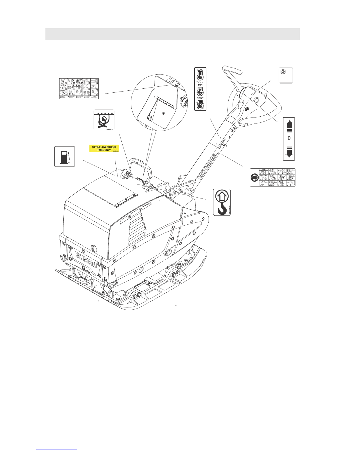
Safety stickers on the machine
Keep safety stickers in good condition and legible
and follow their meaning.
Replace damaged and illegible safety stickers.
Page 18
Safety regulations
BOMAG18 BPR 45/55 D, BPR 55/65 D
Fig. 6
1 Information sticker - Diesel
2 Information sticker - Ultra-low sulphur fuel
3 Information sticker - Lashing point
4 Maintenance sticker
5 Information sticker - Throttle lever
6 Information sticker - Guaranteed sound capac-
ity level
7 Information sticker - Travel lever
8 Brief operating instructions
9 Information sticker - Lifting point
692068
1
DIESEL
6
8
4
7
5
9
3
2
dB
L
WA
Stickers and decals BPR 45/55 D, BPR 55/65 D
Page 19

BOMAG 19BPR 45/55 D, BPR 55/65 D
4 Indicators and Controls
Page 20
Indicators and Controls
BOMAG20 BPR 45/55 D, BPR 55/65 D
4.1 General notes
If you are not yet familiar with the control and display elements on this machine you should read
this section thoroughly before starting any operation on the machine. Here all functions are described in detail.
The section "Operation" contains only brief descriptions of the individual control steps.
4.2 Description of indicators
and control elements
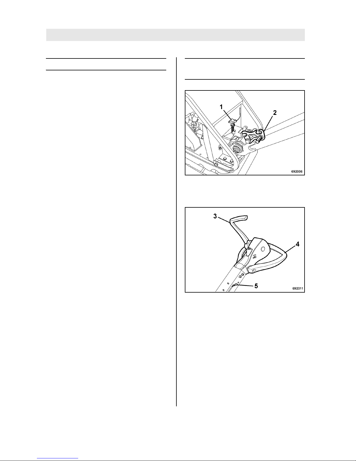
Fig. 7
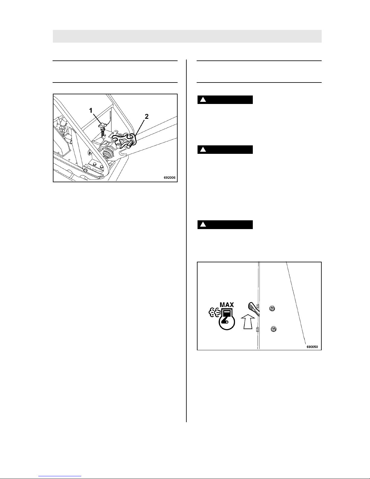
No. 1 = Steering rod height adjustment
No. 2 = Locking pawl lever
Fig. 8
No. 3 = Travel lever
No. 4 = Handle
No. 5 = Throttle lever
Page 21
Indicators and Controls
BOMAG 21BPR 45/55 D, BPR 55/65 D
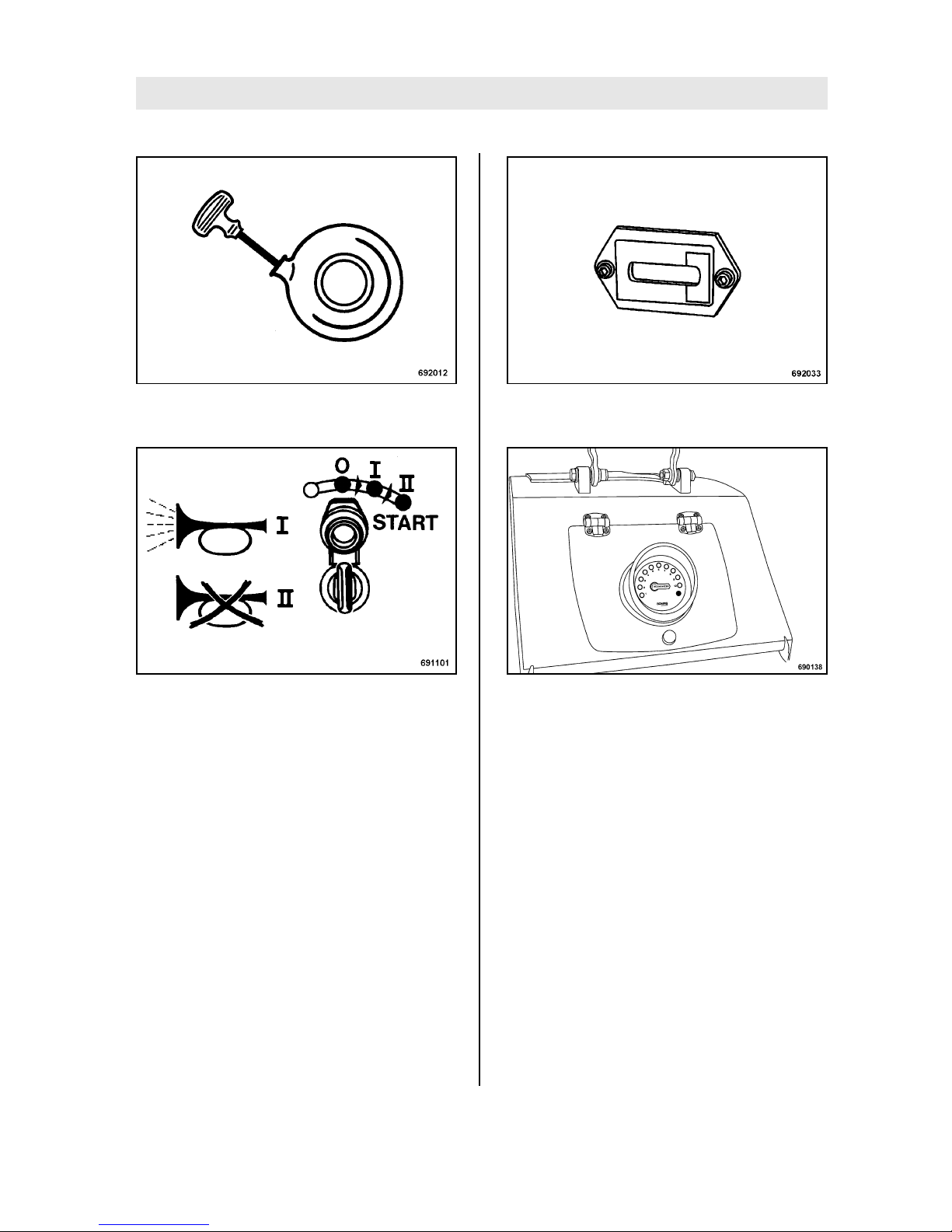
Fig. 9
No. 6 = Recoil starter
Fig. 10
No. 7 = Start switch
Position "0" = Ignition off, warning buzzer off
Position "I" = Ignition on, warning buzzer on
Position "II" = Engine starts, warning buzzer
off
Fig. 11
No. 8 = Operating hour meter
Fig. 12
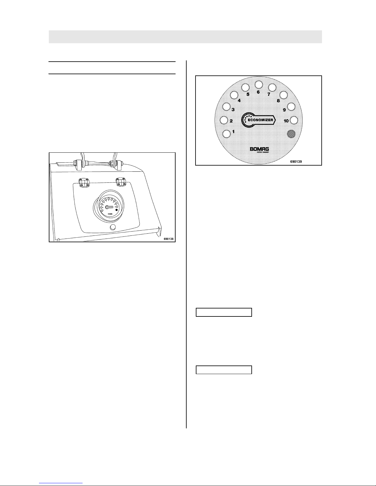
No. 9 = Economizer display
1
1 Optional equipment
Page 22
Indicators and Controls
BOMAG22 BPR 45/55 D, BPR 55/65 D
4.3 Function of the Economizer
Surface covering compaction control is used to determine the dynamic stiffness of the soil. A acceleration sensor measures the reaction of the soil to
the vibrating base plate of the vibratory plate. An
LED display shows the soil stiffness measuring
value as a non-dimensional value.
This continuous measuring display enables the
detection and directed subsequent compaction of
possibly arising weak spots.
Fig. 13
The Economizer consists of two components:
l the evaluation and display module is integrat-
ed in the maintenance flap (within the operator's
view). It shows the measuring value measured by
the compaction control.
l The acceleration sensor is fastened to the
base plate. It converts the accelerations occurring
on the base plate into voltage signals.
For the output of the measuring value in the LED
display the voltage signal from the acceleration
sensor is picked up and processed by the evaluation unit.
In order to achieve the required soil stiffness
measured in MN/m
2
, a reference measurement
(e.g. dynamic load plate) must be made before the
material is compacted.
This is necessary to find out how many LEDs in
the Economizer display correspond with the required value in MN/m
2
on the soil being compact-
ed.
Evaluation and display module
Fig. 14
The yellow LEDs represent the measuring value
from the compaction control in 10 stages.
The brightness of the respective last LED varies in
order to show intermediate values (example: 4,5:
four LEDs are fully on, the fifth LED lights with reduced brightness).
The red LED informs about the system status.
Acceleration sensor
The sensor consists of a sensor element, which is
enclosed in a sensor housing, and a connecting
cable with plug-in connector. Actual sensor, housing, cable and plug-in connector come as a unit,
which cannot be repaired on its own.
The unit is mounted to the base plate of the machine.
Note
i
The Economizer is maintenance free.
Do not clean the front screen with hard objects!
The material may be destroyed. Possibly disturbing scratches can be removed by polishing, e.g.
with lacquer polish.
Note
i
Vibrating plates of the same type show identical
measuring values when used on the same soil.
The measuring values achieved with different vibratory plates with Economizer from BOMAG can
be made comparable by calibration to a reference
value.
Page 23

BOMAG 23BPR 45/55 D, BPR 55/65 D
5Operation
Page 24

Operation
BOMAG24 BPR 45/55 D, BPR 55/65 D
5.1 General
If you are not yet acquainted with the controls
and indicating elements on this machine you
should thoroughly read chapter "Indicators
and control elements" before starting work.
All indicators and control elements are described in detail in this chapter.
5.2 Tests before taking into operation
Note
i
The running in time of the vibratory plate is 25 operating hours.
The following inspections must be carried out before each working day or before a longer working
period.
Danger
!
Danger of accident!
Please observe strictly the safety regulations
in the corresponding section of this instruction manual!
l Park the machine on ground as level as possi-
ble.
l Cleaning the machine.
Check:
l condition of engine and machine.
l fuel tank and fuel lines for leaks.
l screw connections for tight fit.
Note
i
For a description of the following tasks refer to the
chapter "Daily maintenance".
l Check the engine oil level, top up if necessary.
l Check the fuel level, top up if necessary.
l Air filter.
Page 25
Operation
BOMAG 25BPR 45/55 D, BPR 55/65 D
5.3 Folding down the steering
rod
Fig. 15
l Pull the locking pawl lever (2) (Fig. 15) and
lower the steering rod, so that it can swing
freely.
l Adjust the steering rod with the height adjust-
ment (1) to the height of your body.
5.4 Starting the engine electrically
Danger
!
Exhaust gases are highly dangerous!
Always ensure an adequate supply of fresh air
when starting and operating in closed rooms
and trenches!
Danger
!
Danger of accident!
Before starting make sure that there are no
persons in the danger area of engine or machine and that all safety installations are in
place.
Always hold on to the machine.
Always keep an eye on a running machine.
Danger!
Loss of hearing!
Wear your personal noise protection means
(ear defenders) before starting operation.
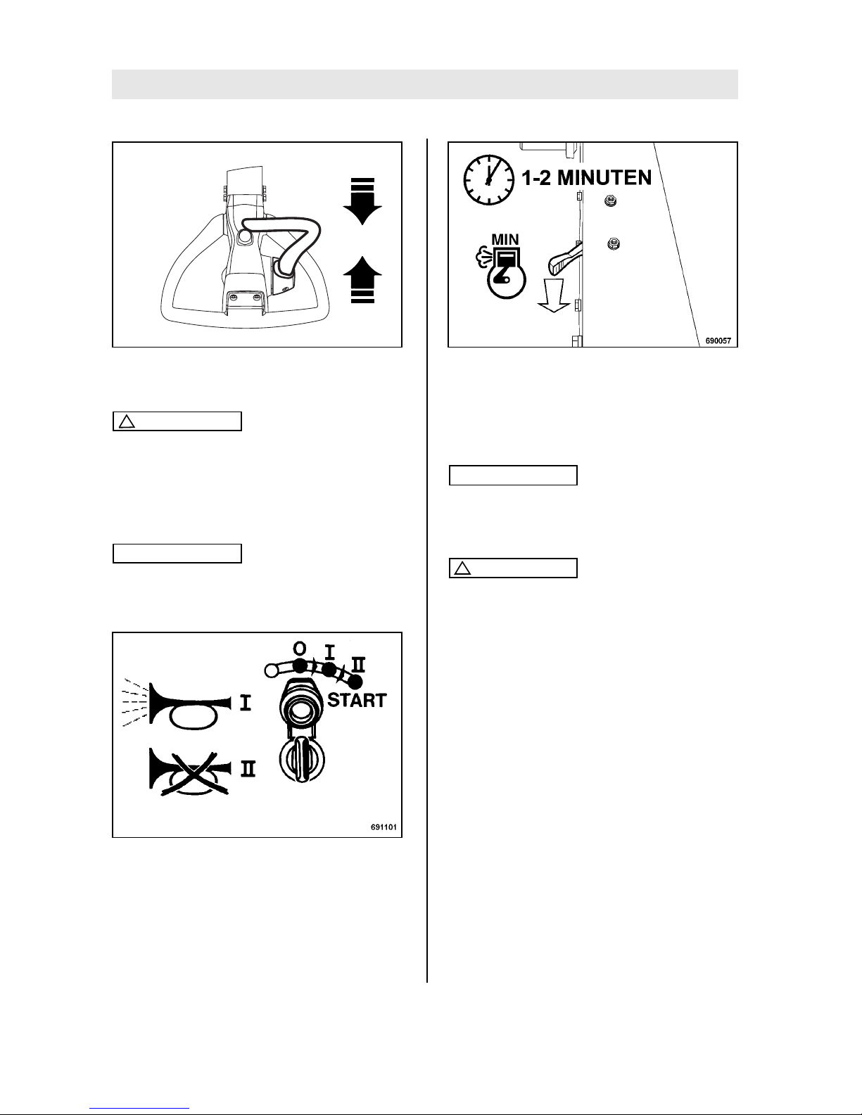
Fig. 16
l Set the throttle lever (Fig. 16) to position
"MAX".
Page 26
Operation
BOMAG26 BPR 45/55 D, BPR 55/65 D
Fig. 17
l Shift the travel lever (Fig. 17) to position "0".
Caution
!
Run the starting process for maximum 20 seconds without interruption and pause for a
minute between starting attempts.
If the engine has not started after two attempts,
determine the cause.
Note
i
The starter switch is designed with a re-start lock.
For a new starting attempt turn the ignition key first
back to position "0".
Fig. 18
l Turn the ignition key to position "I" (Fig. 18),
the warning buzzer sounds.
l Then turn the ignition key further to position "II"
to start the engine.
l As soon as the engine runs, return the ignition
key to position "I". The warning buzzer stops.
Fig. 19
l After starting take the throttle lever back to po-
sition "MIN" (Fig. 19).
l Run the engine warm for approx. 1 to 2 min-
utes in idle speed.
Note
i
Operation of the vibratory plate can be started as
soon as the engine responds to short throttle commands.
Caution
!
When the engine is running leave the ignition
key in position "I".
690184
0
Page 27
Operation
BOMAG 27BPR 45/55 D, BPR 55/65 D
5.5 Starting with recoil starter
Note
i
Starting with the recoil starter should only be used
in case of a defective, discharged or missing battery.
Danger!
Exhaust gases are highly dangerous!
Always ensure an adequate supply of fresh air
when starting and operating in closed rooms
and trenches!
Danger!
Danger of accident!
Before starting make sure that there are no
persons in the danger area of engine or machine and that all safety installations are in
place.
Before starting check the starter rope for chafing, replace if necessary. A damaged rope can
break and cause injuries during starting.
Always hold on to the machine.
Always keep an eye on a running machine.
Danger!
Loss of hearing!
Wear your personal noise protection means
(ear defenders) before starting operation.
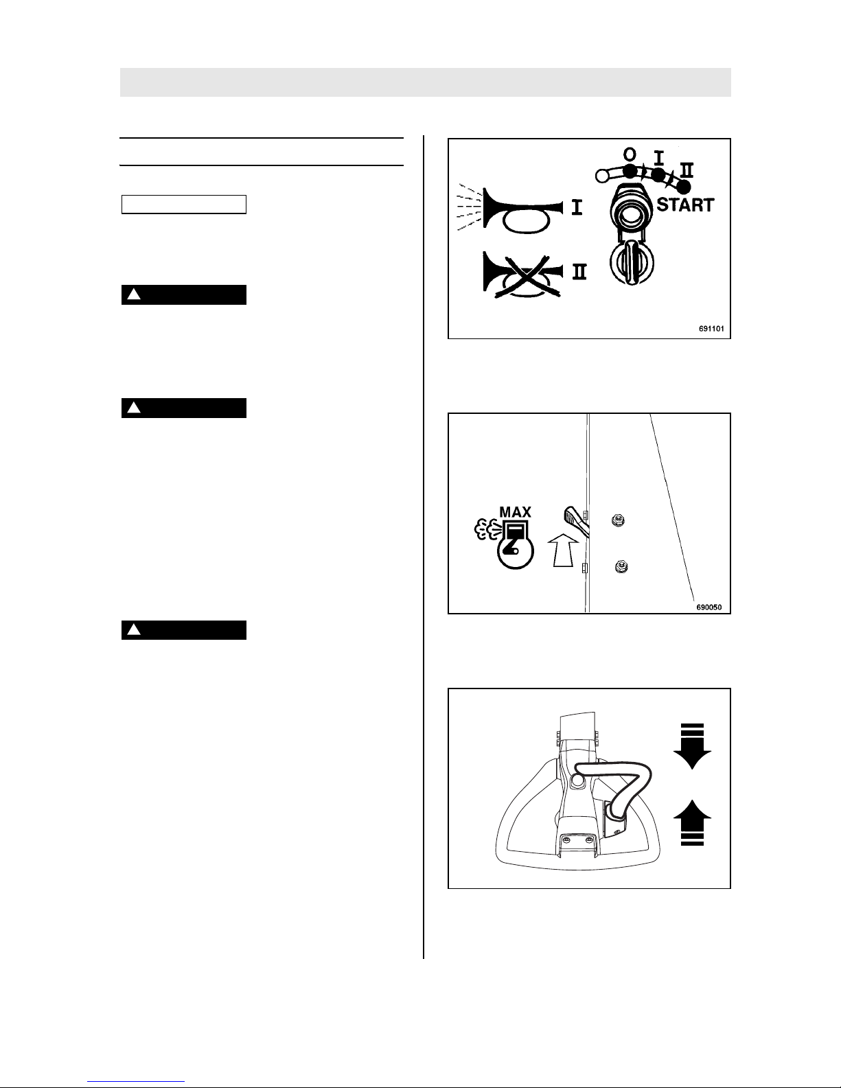
Fig. 20
l Turn the ignition key to position "I" (Fig. 20),
the warning buzzer does not sound.
Fig. 21
l Set the throttle lever (Fig. 21) to position
"MAX".
Fig. 22
l Shift the travel lever (Fig. 22) to position "0".
690184
0
Page 28
Operation
BOMAG28 BPR 45/55 D, BPR 55/65 D
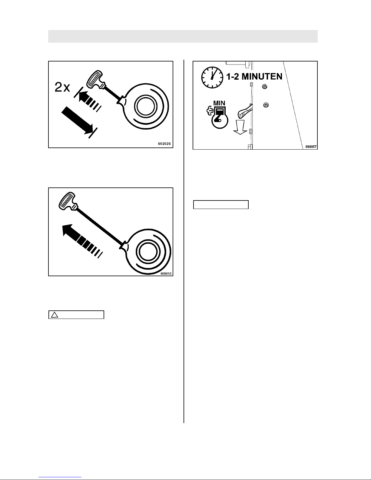
Fig. 23
l Slightly pull the starter handle (Fig. 23) two
times, until resistance can be felt (compression pressure), and return it to initial position.
Fig. 24
l Pull the starter handle (Fig. 24) quickly and
powerful as far out as possible.
Caution
!
Do not let the starter handle hit back, but guide
it back.
l If the engine does not start during the first at-
tempt, repeat the starting process.
Fig. 25
l Set the throttle lever (Fig. 25) to position
"MIN".
l Run the engine warm for approx. 1 to 2 min-
utes in idle speed.
Note
i
Operation of the vibratory plate can be started as
soon as the engine responds to short throttle commands.
Page 29
Operation
BOMAG 29BPR 45/55 D, BPR 55/65 D
5.6 Operation of Economizer
Meaning of display LEDs/self test
The display LEDs signalize the measuring value of
the system. After the corresponding processing by
the evaluation module, the display shows a measurement for the compaction of the soil. The
number of lighting LEDs symbolizes the increasing
compaction of the soil.
The measuring system is automatically started
when switching on the machine. The system first
of all runs a self test of the LED display.
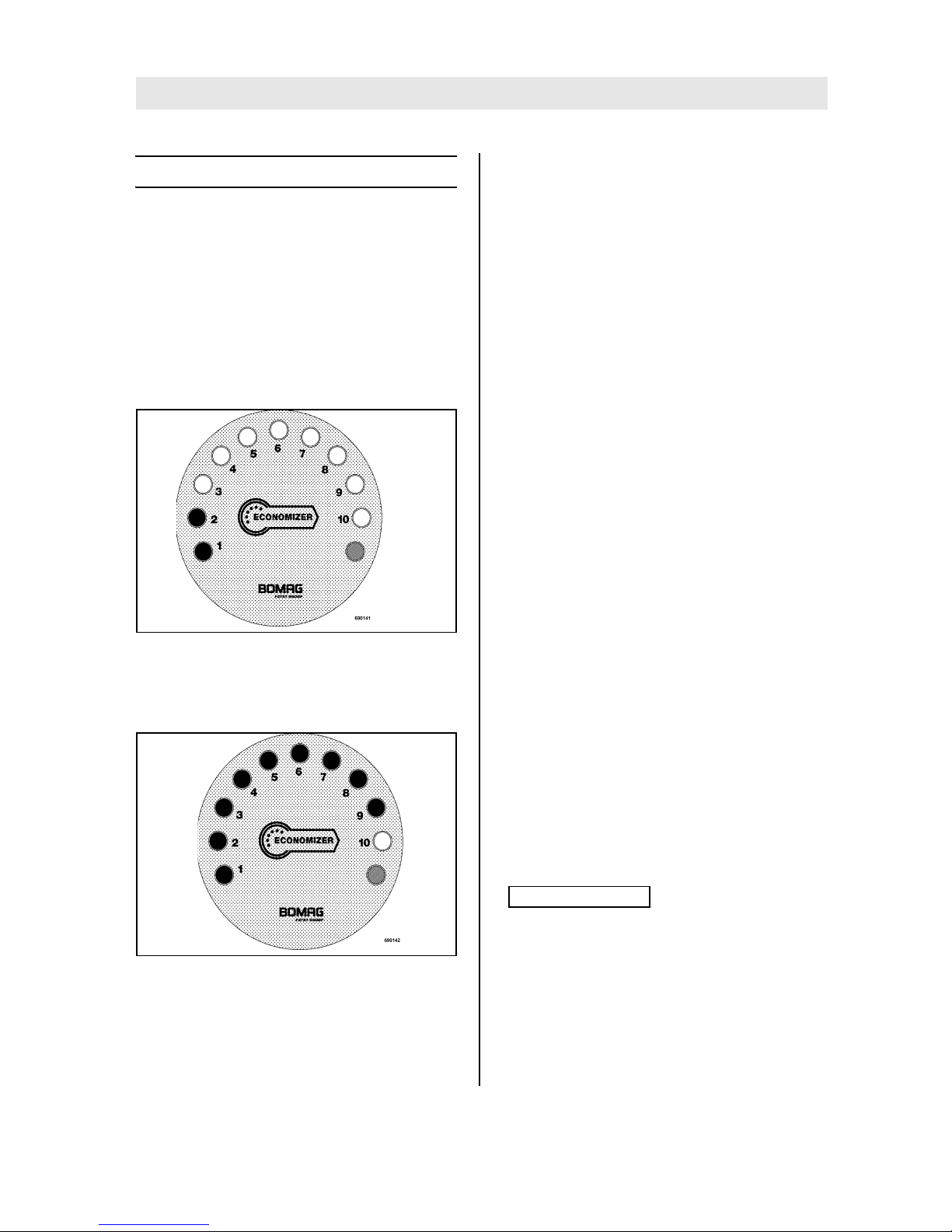
Fig. 26
Self test: the LEDs come on in individual steps
from one to ten. Once all LEDs are on, the display
goes out again in single steps.
Fig. 27
After completion of the self test the system returns
to measuring operation; the status LED (red) first
of all lights permanently; this enables the detection
of possibly existing system faults.
Notes on operation
l Display values higher during the first pass than
during the second pass: the front rounded shape
increases the contact area on loose material, a
slightly higher measuring value may be displayed.
l The Economizer does not reach the maximum
display value, even after many passes: due to different soil stiffness values the maximum value
cannot be reached in each case.
l The display varies during a pass by one point
up/down: caused by slight fluctuations in material
composition and lift height, the mean value indicated during the last pass is decisive.
l The displayed value rises when changing the
travel direction: the effective force applied to the
soil by the vibratory plate rises when reversing the
travel direction. Correct measuring values can
only be achieved in forward and reverse travel with
maximum speed.
l The display rises to the red section, while all
yellow LEDs are on: this signalizes that the maximum possible compaction with this vibratory plate
has been reached.
l When the red status LED is permanently on,
but no other LED lights, the Economizer does not
detect any vibration.
l The red status LED flashes, if the vibration fre-
quency is too low. In order to obtain comparable
Economized measuring values, the vibratory plate
must work with a predetermined frequency. Measuring values obtained with low frequency cannot
be compared with values obtained with high frequency.
l The displayed measuring values are not plau-
sible: weak spots may also be located under the
layer to be compacted and thus adversely affect
compaction of the layers above. In unfavourable
cases an excessively varying material composition or moisture can influence the measuring results.
Note
i
Check the sensor on the base plate for tight fit!
Both screws must be tight.
l Influence of the water content in the soil on the
Economizer: Display of reduced measuring values
in case of to dry or to moist material.
l Influence of extension bars on the measuring
value: Assembling or removing extension bars
changes the contact area and the vibration ampli-
Page 30
Operation
BOMAG30 BPR 45/55 D, BPR 55/65 D
tude. A generally valid statement about the influence on the measuring result cannot be made.
l The measuring values can at present not be
saved and documented.
5.7 Work/operation
Danger!
Danger of accident!
Operate the machine only with the steering rod
folded down.
Guide the machine only by the steering rod.
Guide the machine so hat your hands do not
hit against solid objects.
Always keep an eye on a running machine.
Caution
!
Operate the vibratory plate only with full engine speed, as otherwise the centrifugal clutch
will be destroyed.
For short breaks you should always return the
throttle lever to idle speed position, this avoids
premature wear of the centrifugal clutch.
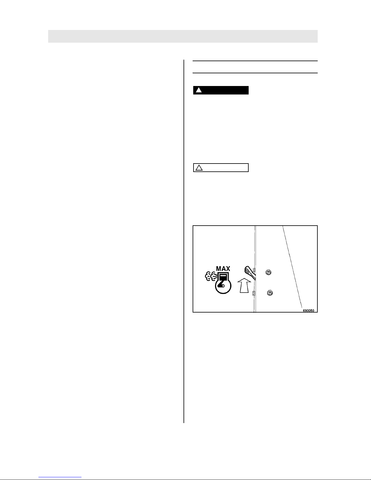
Fig. 28
l Set the throttle lever (Fig. 28) to position
"MAX".
Page 31
Operation
BOMAG 31BPR 45/55 D, BPR 55/65 D
Drive forward
Fig. 29
l Push the travel lever (Fig. 29) forward, until the
vibratory plate has reached the desired speed.
The machines drives with a speed which corresponds with the travel lever position.
Note
i
If the machine moves forward with considerably
reduced speed, pull the travel lever completely
back and shift it forward again.
Drive backwards
Danger!
Danger of accident!
As a measure to avoid injury the machine must
only be guided from the side by the steering
handle
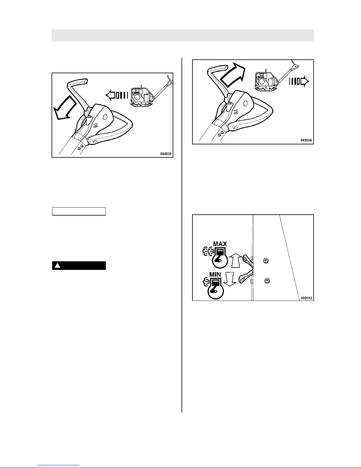
Fig. 30
l Pull the travel lever (Fig. 30) back, until the vi-
bratory plate has reached the desired speed in
reverse.
The machines vibrates backwards with a speed
which corresponds to the travel lever position.
If the vibratory plate got stuck
Fig. 31
l Keep shifting the throttle lever (Fig. 31) be-
tween "MIN" and "MAX" positions.
l At the same time pull the vibratory plate by the
steering rod to the right and left, until it comes
free.
Page 32
Operation
BOMAG32 BPR 45/55 D, BPR 55/65 D
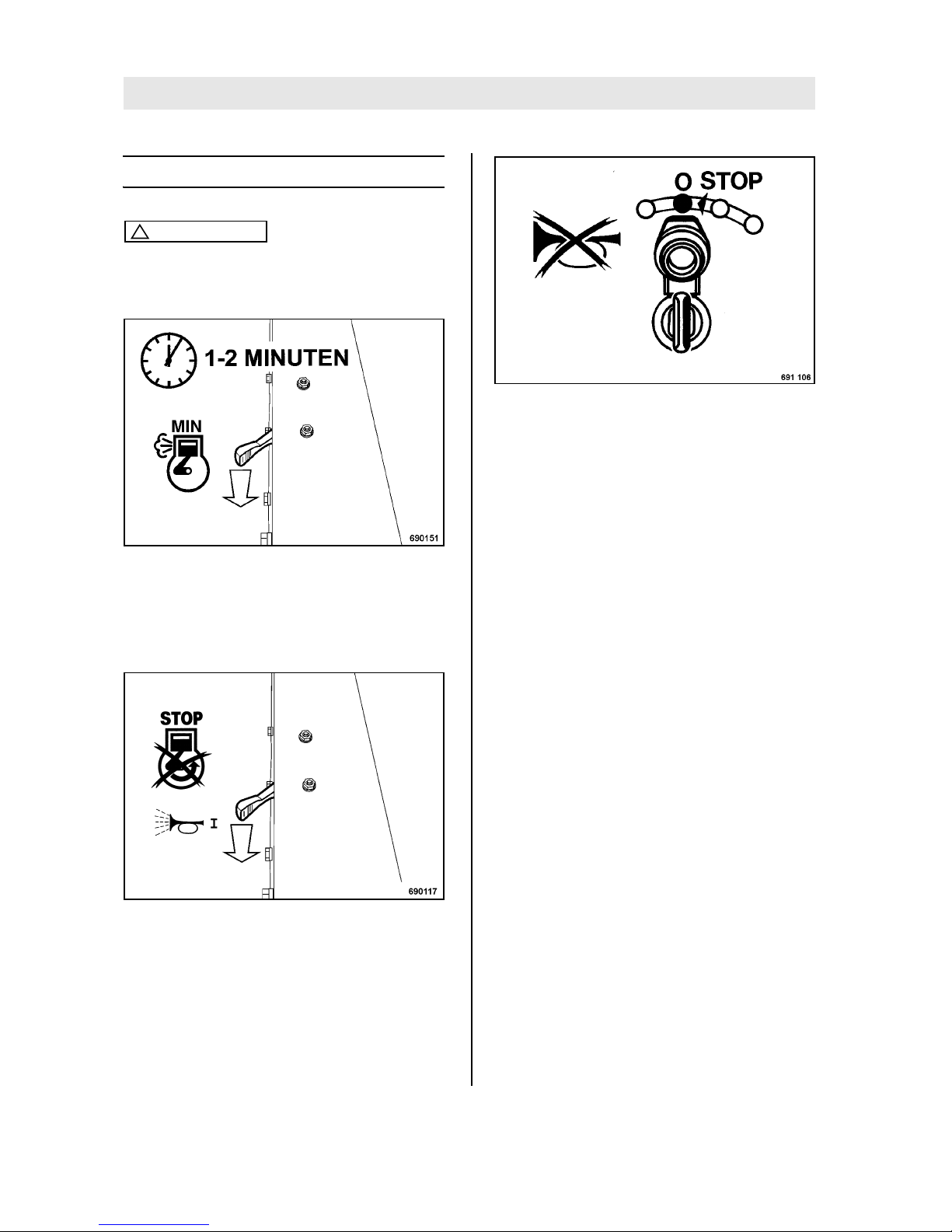
5.8 Shutting down the engine
Caution
!
Do not shut the engine down all of the sudden
from full speed, but let it idle for a while for
temperature equalization.
Fig. 32
l Shift the throttle lever to position "MIN" (Fig.
32) and let the engine run with idle speed for a
short while.
l Vibration is shut down.
Fig. 33
l Set the throttle lever (Fig. 33) to position
"STOP".
The warning buzzer sounds.
Fig. 34
l Turn the ignition key (Fig. 34) to position "0"
and pull it out.
The warning buzzer no longer sounds.
Page 33
Operation
BOMAG 33BPR 45/55 D, BPR 55/65 D
5.9 Loading/transport
Danger!
Danger of accident! Life hazard!
Make sure that persons are not endangered by
the machine tipping or sliding off.
Use only safe lifting gear of sufficient load
bearing capacity Minimum lifting capacity of
lifting gear: see operating weight in chapter
"Technical Data".
Loads must only be attached and hoisted by
an expert (capable person).
For lifting the machine attach the lifting gear
only to the lifting eye provided for this purpose.
Check lifting eye for damage before use. Do
not use a damaged or in any other way impaired lifting eye.
Do not lift or lower the machine jerkily.
The tension must always be effective in vertical direction.
The machine must not swing about when being lifted.
Do not step or stand under suspended loads.
Always use suitable lashing gear on the lifting
points to lash down the machine.
Lash the machine down, so that it is secured
against rolling, sliding and turning over.
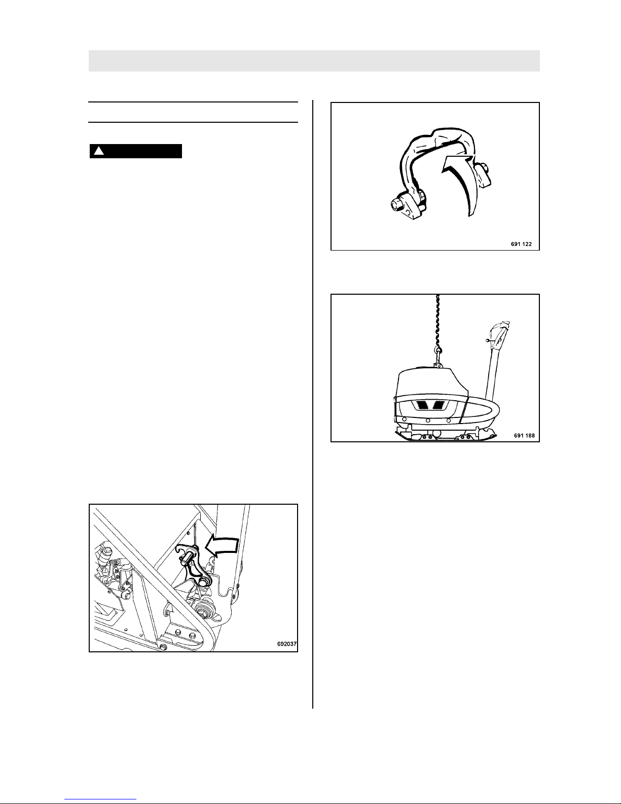
Fig. 35
l Adjust the steering rod upright and engage the
locking lever (Fig. 35).
Fig. 36
l Fold the lifting hook (Fig. 36) up.
Fig. 37
l Always attach the lifting tackle to the lifting eye
to load the vibratory plate (Fig. 37) on a transport vehicle.
l Lash the vibratory plate down to the transport
vehicle, so that it is secured against rolling,
sliding and turning over. Fasten the lashing
tackle at the marked lashing points.
Page 34

Operation
BOMAG34 BPR 45/55 D, BPR 55/65 D
Page 35

BOMAG 35BPR 45/55 D, BPR 55/65 D
6 Maintenance
Page 36
Maintenance
BOMAG36 BPR 45/55 D, BPR 55/65 D
6.1 General notes on maintenance
When performing maintenance work ensure strict
compliance with the respective safety instructions
and particularly the safety regulations mentioned
in the corresponding section of these operating
and maintenance instructions.
Thorough maintenance of the machine guarantees far longer safe functioning of the machine and
prolongs the lifetime of important components.
The effort needed for this work is only little compared with the problems that may arise when not
observing this rule.
l Always clean machine and engine thoroughly
before starting maintenance work.
l For maintenance work stand the machine on
level ground.
l Do not touch hot engine parts.
l Perform maintenance work only with the en-
gine shut down.
Environment
During maintenance work catch all oils and fuels and do not let them seep into the ground or
into the sewage system. Dispose of oils and fuels environmentally.
Keep used filters in a separate waste container
and dispose of environmentally.
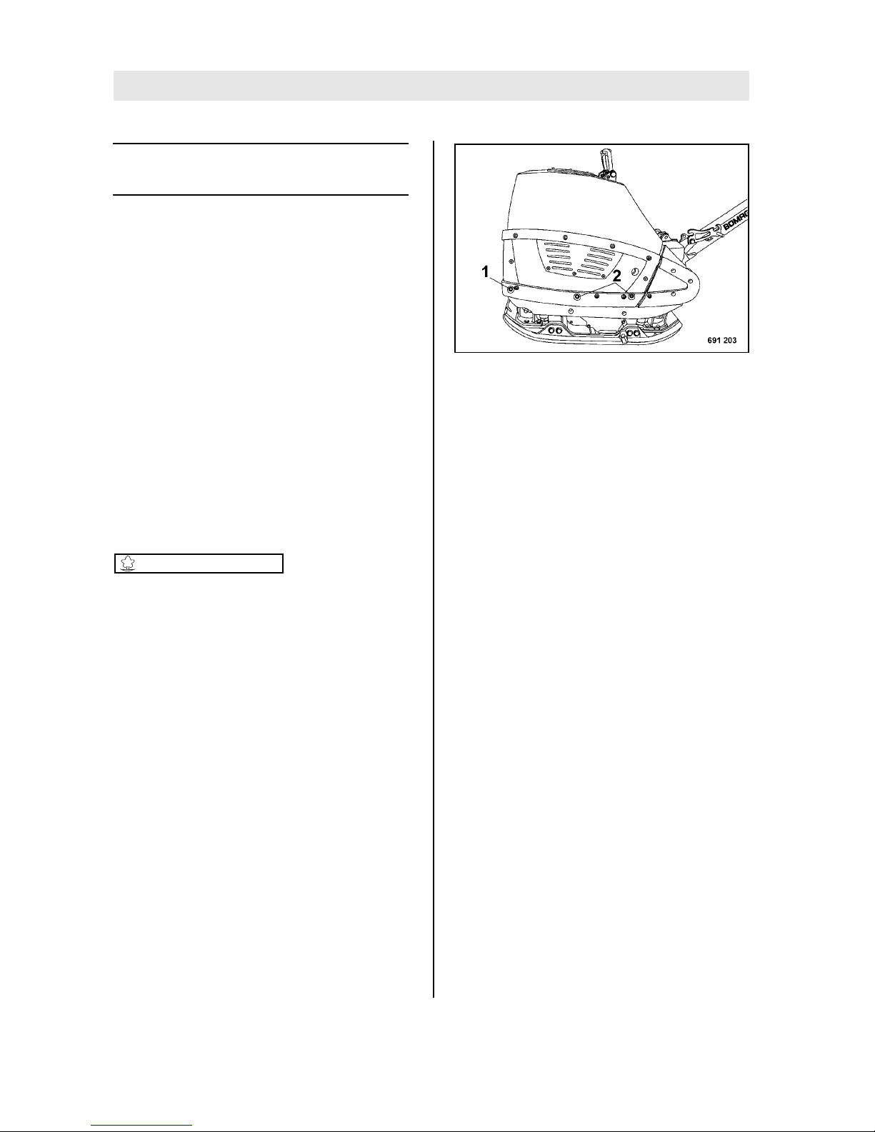
l Open the hood to perform maintenance work.
Fig. 38
l Loosen the hood fasteners (1) on both sides
and remove the fasteners (2) from both sides
(Fig. 38).
l Fold the hood back.
Notes on the fuel system
The lifetime of the diesel engine depends to a
great extent on the cleanliness of the fuel.
l Keep fuel free of contaminants and water,
since this will damage the injection elements
of the engine.
l Drums with inside zinc lining are not suitable to
store fuel.
l The fuel drum must rest for a longer period of
time before drawing off fuel.
l Under no circumstances must the drum be
rolled to the tapping point just before drawing
out fuel.
l When choosing the storage place for fuel
make sure that spilled fuel will not harm the environment.
l Do not let the hose stir up the slurry at the bot-
tom of the drum.
l Do not draw off fuel from near the bottom of
the drum.
l Fuel residues in the drum are not suitable for
the engine.
Notes on the performance of the engine
On diesel engines both combustion air and fuel injection quantities are thoroughly adapted to each
Page 37
Maintenance
BOMAG 37BPR 45/55 D, BPR 55/65 D
other and determine power, temperature level and
exhaust gas quality of the engine.
If your engine has to work permanently in "thin air"
(at higher altitudes) and under full load, you should
consult our customer service or the customer service of the engine manufacturer.
Frequent causes of faults
l Operating errors
l Incorrect, inadequate maintenance
If you cannot locate the cause of a fault or rectify it
yourself by following the trouble shooting chart,
you should contact our customer service department.
6.2 Fuels and lubricants
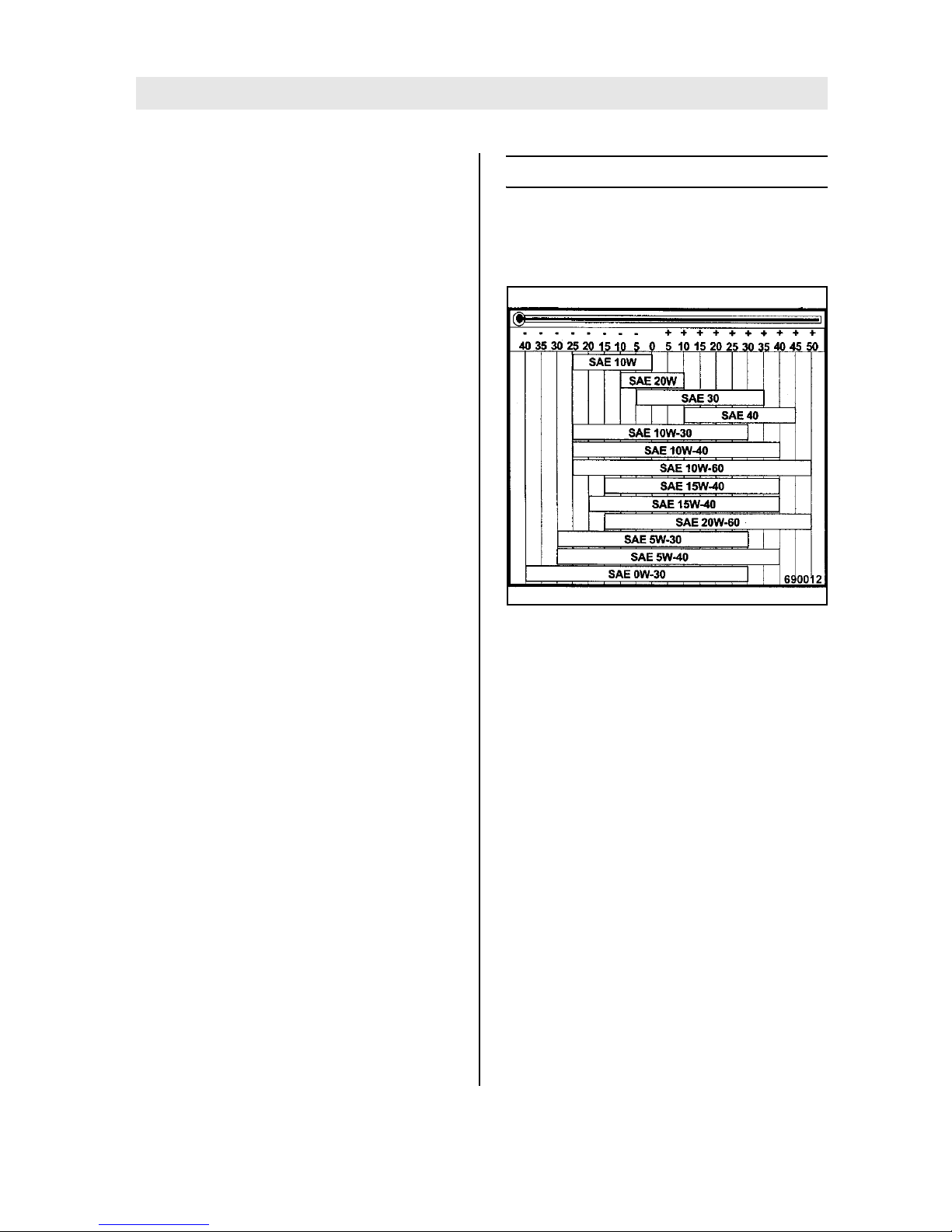
Engine oil
Oil viscosity
Fig. 39
Choose the oil viscosity in dependence on the ambient temperature at the operating location of the
engine (see diagram).
Occasional falling short of the temperature limit
(e.g. use of SAE 15W/40 down to -15 °C (+5 °F))
may effect the cold starting ability of the engine,
but will not cause any engine damage.
Temperature related lubrication oil changes can
be avoided by using multi-purpose oils. The following oil change intervals apply also when using multi-purpose oils.
Oil quality
Use oils of the following quality classes:
l API: CF-4/CG-4
l ACEA: B2/E2
l MIL-L46152 D/E
Lubrication oil change intervals
Annually or every 250 operating hours
Page 38

Maintenance
BOMAG38 BPR 45/55 D, BPR 55/65 D
Fuel
Quality
You should only use commercially available brand
diesel fuel and ensure strict cleanliness when filling in.
Since this engine complies with the exhaust gas
standard acc. to EPA
1
Stage “TIER 4”, the use of
ultra-low sulphur diesel fuel is mandatory, if the
engine is operated within an area where compliance with EPA is required.
The fuel provision should always be topped up in
due time, so that the tank will not run dry.
The following fuel specifications are permitted:
l EN 590
l ASTM D 975 1-D and 2-D
Winter fuel
For winter operation use only winter diesel fuel, to
avoid clogging because of paraffin separation. At
very low temperatures disturbing paraffin separation can also be expected when using winter diesel
fuel.
Mineral oil based hydraulic oil
The hydraulic system is operated with hydraulic oil
HV 32 (ISO) with a kinematic viscosity of 32 mm
2
/
s at 40°C (104 °F).
For topping up or for oil changes use only highquality hydraulic oil, type HVLP according to DIN
51524, part 3, or hydraulic oils type HV according
to ISO 6743/3. The viscosity index (VI) should be
at least 150 (observe information of manufacturer).
1 United States Environmental Protection Agency
Page 39

Maintenance
BOMAG 39BPR 45/55 D, BPR 55/65 D
6.3 Table of fuels and lubricants
Assembly Fuel or lubricant Quantity
Summer Winter Attention!
Observe the level marks
Motor
- Engine oil Specification see "Fuels and lubricants - engine oil" approx. 1.5 l (0.4 gal us)
up to oil level mark
SAE 15W-40
(-15 °C to +40 °C) (+5 °F to +104 °F)
SAE 30
(-5 °C to +35 °C)
(+23 °F to +95 °F)
SAE 10W
(-25 °C to 0 °C)
(-13 °F to +32 °F)
SAE 40
(+10 °C to +45 °C)
(+50 °F to +113 °F)
SAE 20
(-10 °C to +10 °C)
(+14 °F to +50 °F)
- Fuel Diesel Winter diesel fuel
(down to -12 °C) (+10.4
°F)
approx. 5.0 l (1.3 gal us)
Vibrator shaft housing as engine oil approx. 0.45 l (0.12 gal
us)
Steering rod Hydraulic oil: HV 32 approx. 0.40 l (0.11 gal
us)
Page 40

Maintenance
BOMAG40 BPR 45/55 D, BPR 55/65 D
6.4 Running-in instructions
The following maintenance work must be performed when running in new machines or
overhauled engines:
Caution
!
During the running-in period, up to approx. 200
operating hours, check the engine oil level
twice every day.
Depending on the load the engine is subjected
to, the oil consumption will drop to the normal
level after approx. 100 to 200 operating hours.
After approx. 50 operating hours
l Change the engine oil.
l Check engine and machine for leaks.
l Retighten the fastening screws on air filter ex-
haust, fuel tank and other attachments.
l Retighten the bolted connections on the ma-
chine.
l Check the vibration drive V-belts.
l Check the oil level in the vibrator housing.
Page 41

Maintenance
BOMAG 41BPR 45/55 D, BPR 55/65 D
6.5 Maintenance table
No. Maintenance work Comment
daily
monthly
half-annually
annually
as required
6.6
Clean the machine X
6.7
Check the engine oil level Dipstick mark X
6.8
Check the fuel level X
6.9
Check, clean the air filter, replace if necessary replace at least 1 x
year
X
6.10
Clean the cooling fins and the cooling air intake
openings
X
6.11
Drain the sludge from the fuel tank X
6.12
Check condition of battery X
6.13
Check the oil level in the exciter housing X
6.14
Check the V-belt tension, if necessary replace
the V-belt
X
6.15
Change engine oil and oil filter at least every 250
operating hours
X
6.16
Replace the fuel filter X
6.17
Change the oil in the exciter housing at least every 500
operating hours
X
6.18
Check the hydraulic oil level X
6.19
Check the rubber buffers X
6.20
Tighten all bolted connections X
6.21
Engine conservation X
Page 42

Maintenance
BOMAG42 BPR 45/55 D, BPR 55/65 D
Page 43
Maintenance every day
BOMAG 43BPR 45/55 D, BPR 55/65 D
Maintenance every day
6.6 Clean the machine
Caution
!
Perform cleaning work only after the engine
has cooled down and with the engine stopped.
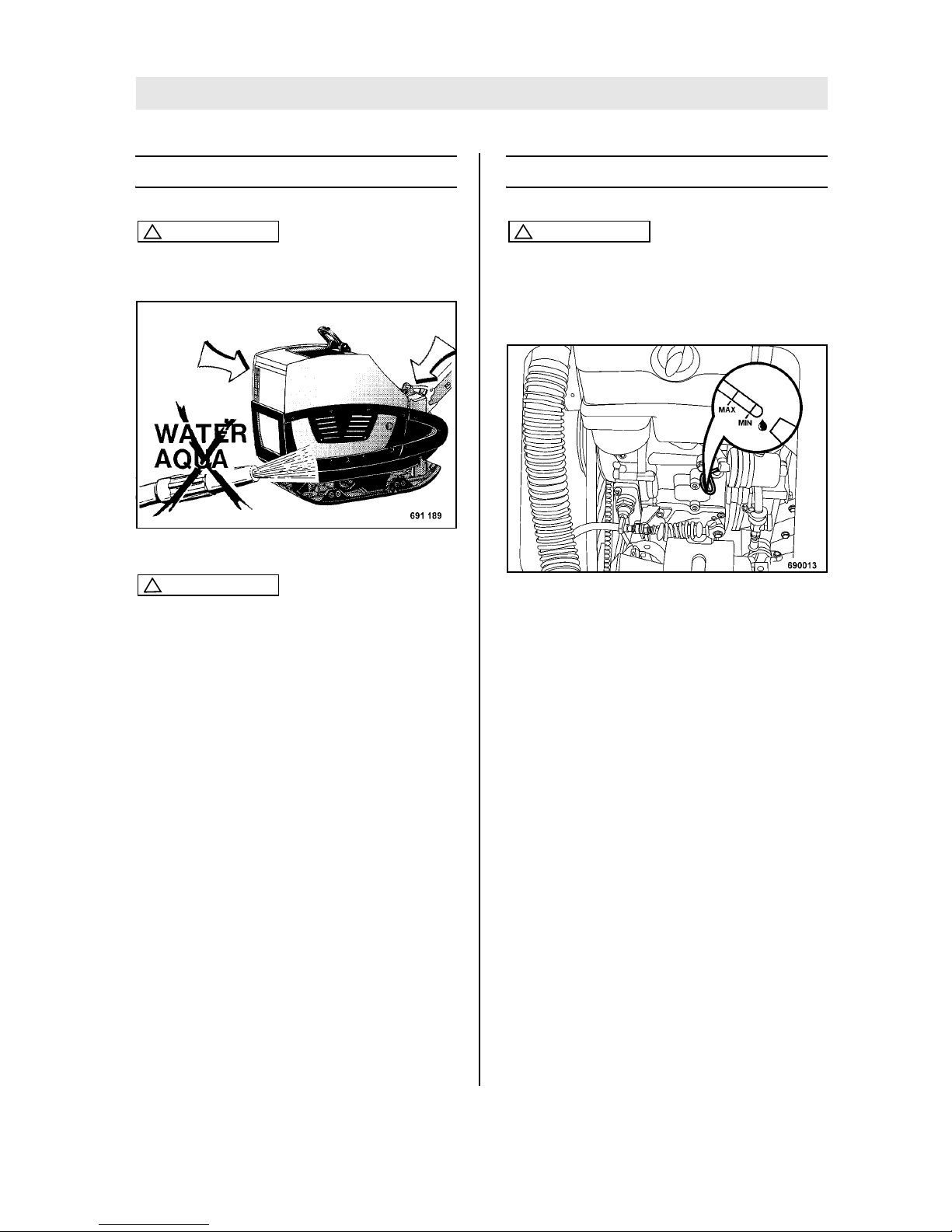
Fig. 40
Caution
!
Do not guide the water jet directly into the dry
air filter intake opening (Fig. 40) and into the
opening for the crank handle. Cover the electric equipment against the direct water jet.
l After wet cleaning run the engine warm to
evaporate all water residues and to avoid corrosion.
6.7 Check the engine oil level
Caution
!
Park the machine on level ground so that the
engine is in horizontal position.
For quality of oil refer to the "table of fuels and
lubricants".
Fig. 41
l Shut down the engine.
l Open the rear rubber cover.
l Pull the dipstick (Fig. 41) out, wipe it off with a
lint-free, clean cloth and reinsert it until it bottoms.
l Pull out the oil dipstick again and read the oil
level.
l The oil level should reach the upper mark on
the dipstick. If the oil level is too low top up oil
immediately.
l After a running time of approx. one minute
shut the engine down, wait until all oil has run
back into the oil sump, check the oil level.
Page 44
Maintenance every day
BOMAG44 BPR 45/55 D, BPR 55/65 D
6.8 Check the fuel level
Danger!
Fire hazard!
When working on the fuel system do not use
open fire, do not smoke, do not spill any fuel.
Do not refuel in closed rooms.
Shut down the engine.
Danger
!
Health hazard!
Do not inhale any fuel fumes.
Environment
Catch running out fuel, do not let it seep into
the ground.
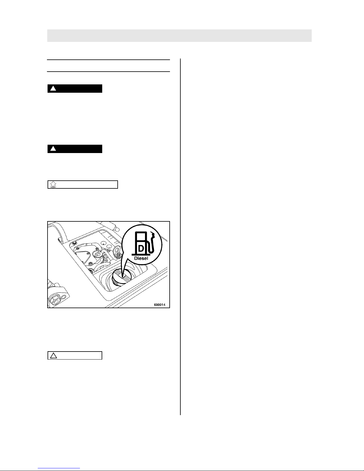
l Open the opper rubber cover.
Fig. 42
l Clean the area around the filler opening.
l Open the filler cap on the fuel tank (Fig. 42)
and check the fuel level visually.
Caution
!
Contaminated fuel can cause malfunction or
even damage of the engine.
For quality and quantity of fuel refer to the "table of fuels and lubricants".
l If necessary, fill in fuel through a funnel with
screen filter.
l Close the fuel tank tightly.
Page 45
Maintenance every day
BOMAG 45BPR 45/55 D, BPR 55/65 D
6.9 Check, clean the air filter,
replace if necessary
Caution
!
Do not use gasoline or hot fluids to clean the
air filter.
Do not continue to use a damaged air filter element. If in doubt use a new air filter.
The air filter must be changed after several
times cleaning, but at the latest after one year.
Each cleaning interval must be marked with a
cross on the cover of the air filter.
Cleaning does not make sense if the air filter
element is covered with a sooty deposit. Use a
new air filter.
Incorrectly handled air filters may become ineffective because of damage (e.g. cracks) and
cause damage to the engine.
In case of wet or oily dirt replace the filter element.
Note
i
Under extremely dusty conditions it may be necessary to clean several times a day.
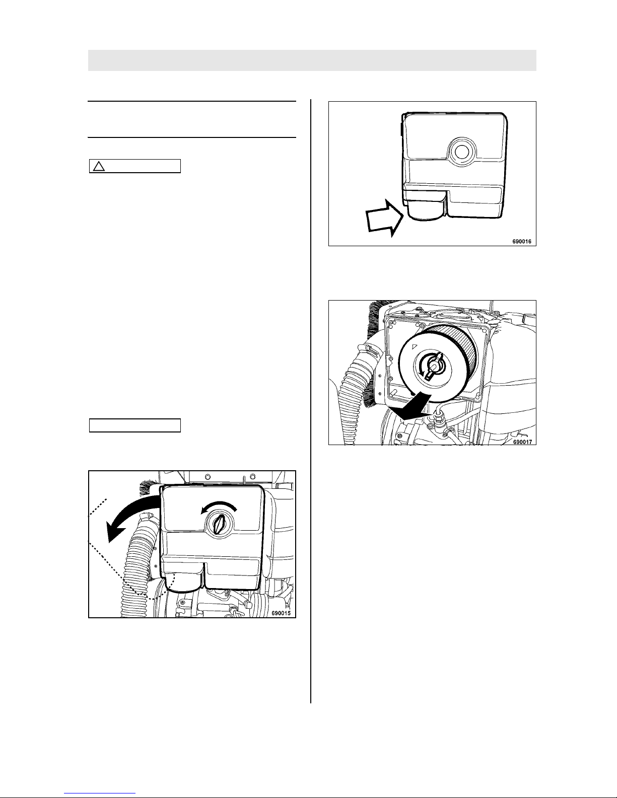
Fig. 43
l Unscrew the wing nut and remove the housing
cover (Fig. 43).
l Clean the housing cover from inside.
Fig. 44
l Check the pre-filter in the housing cover for dirt
or blockage, clean if necessary (Fig. 44).
Fig. 45
l Unscrew the wing nut and pull the air filter out
(Fig. 45).
Page 46
Maintenance every day
BOMAG46 BPR 45/55 D, BPR 55/65 D
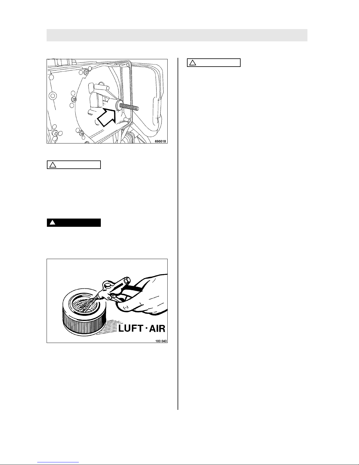
Fig. 46
Caution
!
Contaminants or dirt must not enter into the intake channel.
l Check the rubber seal, if necessary replace
the damaged rubber seal (Fig. 46).
l Clean out the air filter housing with a cloth.
Danger
!
Danger of injury!
Always wear protective clothes (goggles,
gloves) when working with compressed air.
Fig. 47
l Blow the air filter out from inside to outside with
dry compressed air (max. 5 bar (72 psi)) (Fig.
47).
l Check the air filter for damage, replace if nec-
essary.
l Insert the air filter correctly and tighten the
wing nut.
Caution
!
If the air filter is not correctly inserted, dust
and foreign particles can enter into the air intake channel.
l Fasten the housing cover with the wing nut.
Page 47
Maintenance every month
BOMAG 47BPR 45/55 D, BPR 55/65 D
Maintenance every month
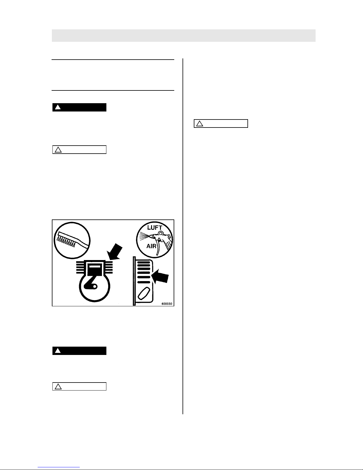
6.10 Clean the cooling fins and
the cooling air intake openings
Danger
!
Danger of injury!
Always wear protective clothes (goggles,
gloves) when working with compressed air.
Caution
!
Dirty operating conditions, particularly lubrication oil and fuel deposits on the cooling fins
of the engine and the cooling air intake opening have an adverse effect on the cooling of
the engine.
You should therefore immediately seal any oil
or fuel leaks near fuel tank, cylinder or cooling
air intake.
Fig. 48
l Loosen dried on dirt with a suitable brush (Fig.
48) from all cooling fins and cooling air intake
openings and blow it off with compressed air .
Danger
!
Fire hazard!
Do not use any inflammable solvents.
Caution
!
Do not guide the water jet directly into the
cooling air openings of the recoil starter, into
the air filter and on electrical equipment.
l On a oil contaminated engine use a cold
cleansing agent for cleaning.
l After a sufficient soaking time clean off with a
water or steam jet and blow out with compressed air.
l Run the engine warm for a while to avoid cor-
rosion.
Caution
!
Look for the cause of oily contamination and
have any leaks sealed by our customer service.
Page 48
Maintenance every month
BOMAG48 BPR 45/55 D, BPR 55/65 D
6.11 Drain the sludge from the
fuel tank
Danger
!
Fire hazard!
When working on the fuel system do not use
open fire, do not smoke, do not spill any fuel.
Danger
!
Health hazard!
Do not inhale any fuel fumes.
Environment
Any fuel must be caught and disposed of in an
environmentally friendly manner.
Note
i
For this work the fuel tank should contain only a little quantity of fuel.
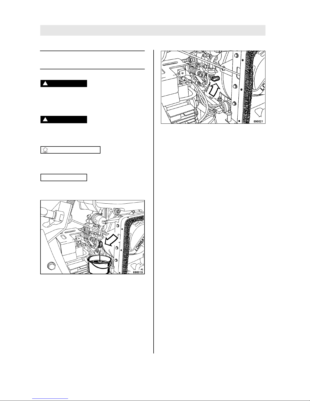
Fig. 49
l Open the drain cock (Fig. 49), drain off and
catch the fuel.
Fig. 50
l Close the drain cock after all fuel has run out
(Fig. 50).
Page 49
Maintenance every 6 months
BOMAG 49BPR 45/55 D, BPR 55/65 D
Maintenance every 6 months
6.12 Check the battery condition,
grease the poles
Danger
!
Danger of burning!
When working on the battery do not use open
fire, do not smoke!
Do not let acid come in contact with skin or
clothes!
Wear safety goggles!
Do not lay any tools on the battery!
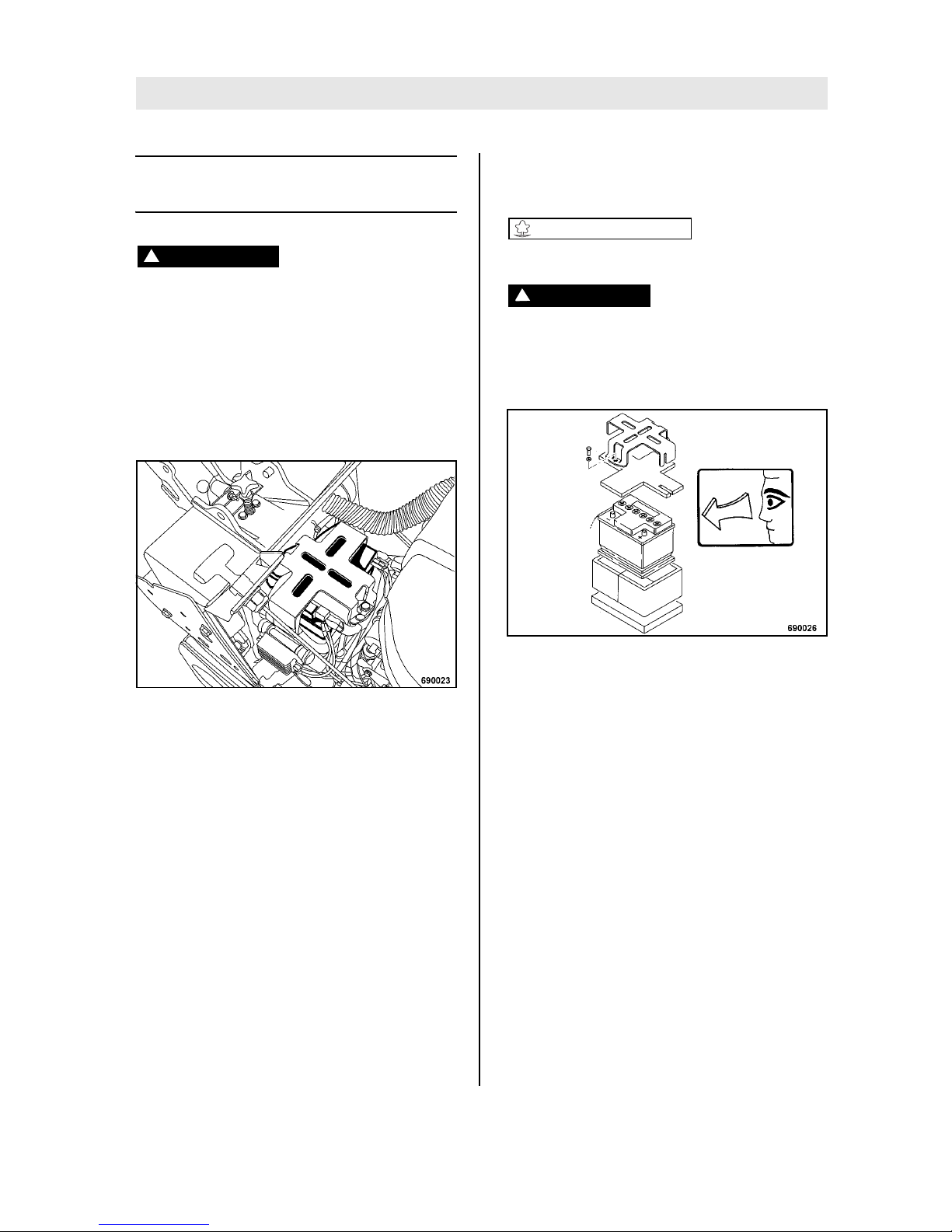
Fig. 51
l Unscrew the battery holder (Fig. 51).
l Remove the vibration damper mat.
Non-maintenance free batteries:
l Clean battery and battery compartment.
l Open plugs and check the acid level.
With control inserts:
l Check whether the acid level reaches the bot-
tom end of the control inserts.
With transparent battery housing:
l Check whether the acid level reaches the level
mark on the housing.
Maintenance free batteries:
l Clean the battery
l Grease the poles
l Tighten the terminal clamps
Environment
Dispose of the old batteries environmentally.
Danger
!
Development of gas!
For recharging remove the plugs from the battery to avoid the accumulation of highly explosive gases.
Fig. 52
l Clean the condition of the vibration insulation
mats, replace if necessary (Fig. 52).
l Retighten the battery holder.
Page 50
Maintenance every 6 months
BOMAG50 BPR 45/55 D, BPR 55/65 D
6.13 Check the oil level in the exciter housing
Caution
!
Park the machine on level ground.
l Clean the area around breather and drain
plug.
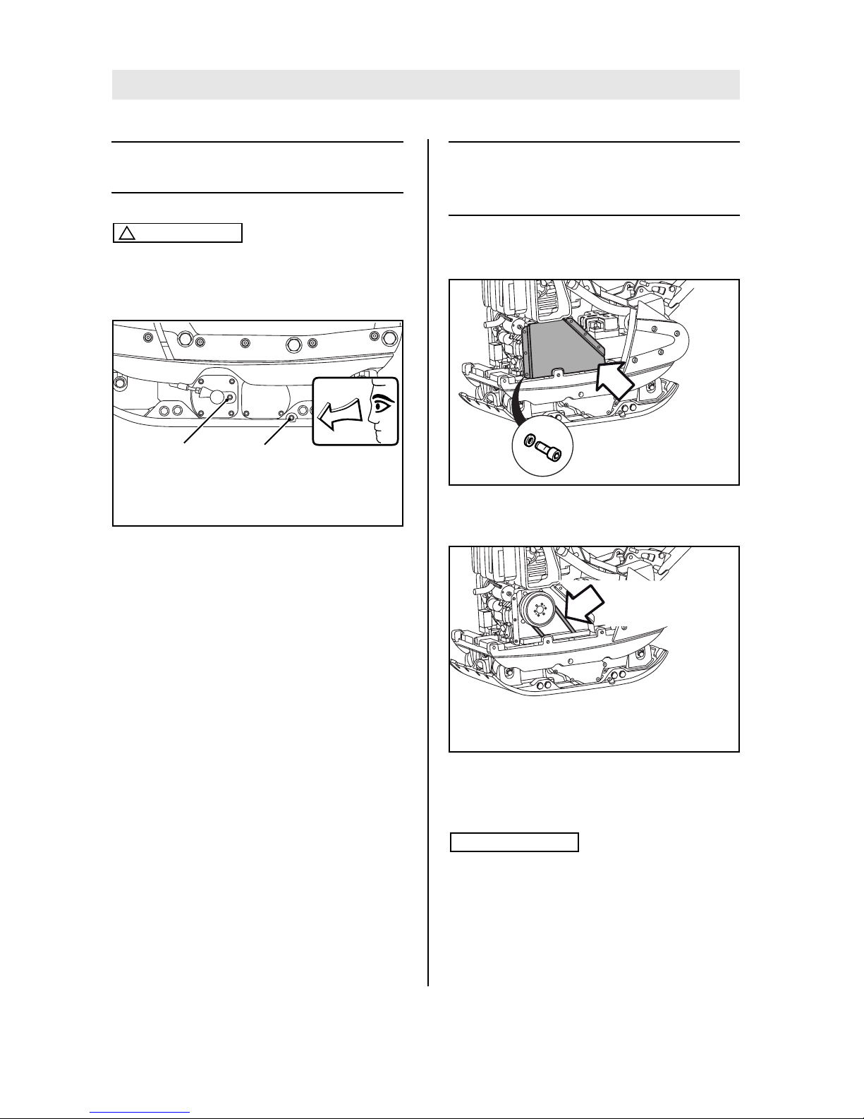
Fig. 53
l Unscrew the bleeding screw (1) (Fig. 53).
l Unscrew the oil level inspection plug (2) and
check the oil level.
l The oil level must reach the bottom edge of the
inspection opening, if necessary fill in oil.
For quality of oil refer to the "table of fuels and
lubricants".
l Clean the oil level inspection plug and screw in
with sealing agent (e.g. BOMAG 009 700 16).
l Screw the bleeding screw back in.
6.14 Check the V-belt tension, if
necessary replace the Vbelt
Checking the V-belt
Fig. 54
l Remove the V-belt guard (Fig. 54).
Fig. 55
l Check condition and tightness of V-belt (Fig.
55).
Note
i
Compression measurement: approx. 10 to 25 mm
(0.59 to 0.98 in)
692080
1 2
692070
692071
ca. 10-25 mm
appr. 0.59-0.98 in
Page 51
Maintenance every 6 months
BOMAG 51BPR 45/55 D, BPR 55/65 D
Caution
!
Replace a damaged V-belt.
The V-belt cannot be tightened manually. Always replace the V-belt, if the compression
measurement is exceeded.
Replacing the V-belt
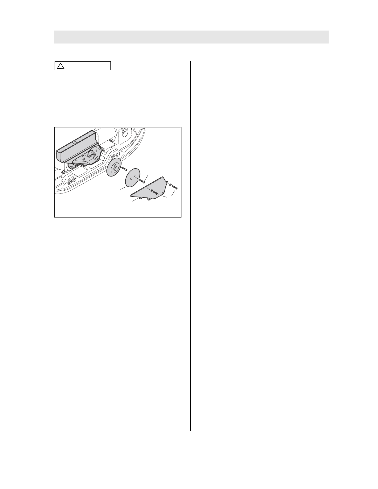
Fig. 56
l Remove the safety cover (3) (Fig. 56).
l Loosen screw (2).
l Remove the front disc (1) from the centrifugal
clutch.
l Take off the V-belt and replace it by a new one.
l Attach the front disc (1).
l Tighten the screws (2).
l Reinstall the protective cover (3) and tighten
the screws (4) (tightening torque 15 Nm (11
ft.lbs)).
l Install the top V-belt guard (Fig. 54).
692078
1
3
4
2
Page 52

Maintenance every 6 months
BOMAG52 BPR 45/55 D, BPR 55/65 D
Page 53
Maintenance every year
BOMAG 53BPR 45/55 D, BPR 55/65 D
Maintenance every year
6.15 Change engine oil and oil filter
Danger
!
Danger of scalding!
When draining off hot oil.
By hot oil when changing the engine oil filter.
Caution
!
Park the machine on level ground.
Drain the engine oil only when the engine is
warm.
For quality and quantity of oil refer to the "table
of fuels and lubricants".
Environment
Catch running out oil and dispose of environmentally together with the oil filter.
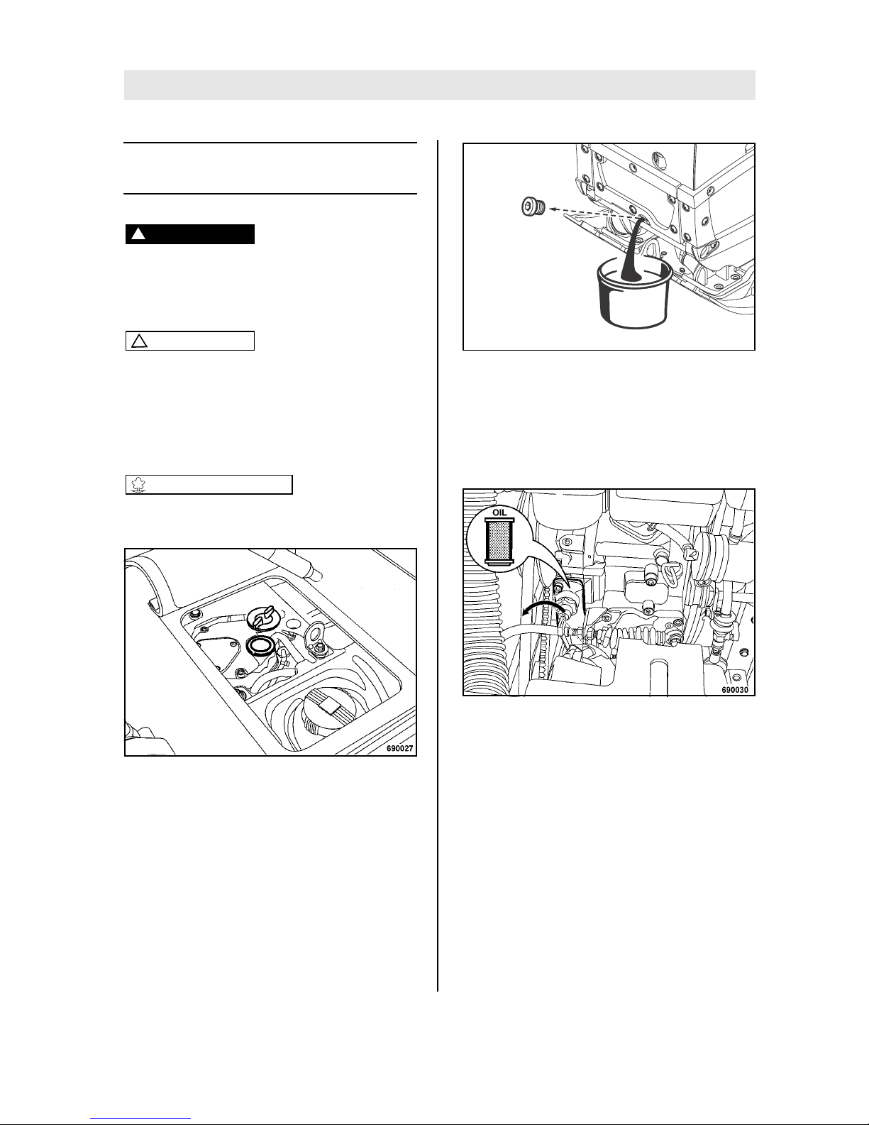
Fig. 57
l Unscrew the oil filler cap (Fig. 57).
Fig. 58
l Clean the drain hose from dust and dirt.
l Unscrew the oil drain plug and catch any oil
running out (Fig. 58).
l Clean the oil drain plug and screw it back in
(tightening torque: 15 Nm (11 ft.lbs)).
Fig. 59
l Clean the oil filter flange.
l Unscrew both screws and take off the oil filter
flange (Fig. 59).
l Pull the oil filter out.
l Wipe the sealing face on the engine clean.
l Use a new filter cartridge.
l Check the seal on the oil filter flange, replace
if necessary.
l Screw the oil filter flange in tightly.
OIL
692069
Page 54
Maintenance every year
BOMAG54 BPR 45/55 D, BPR 55/65 D
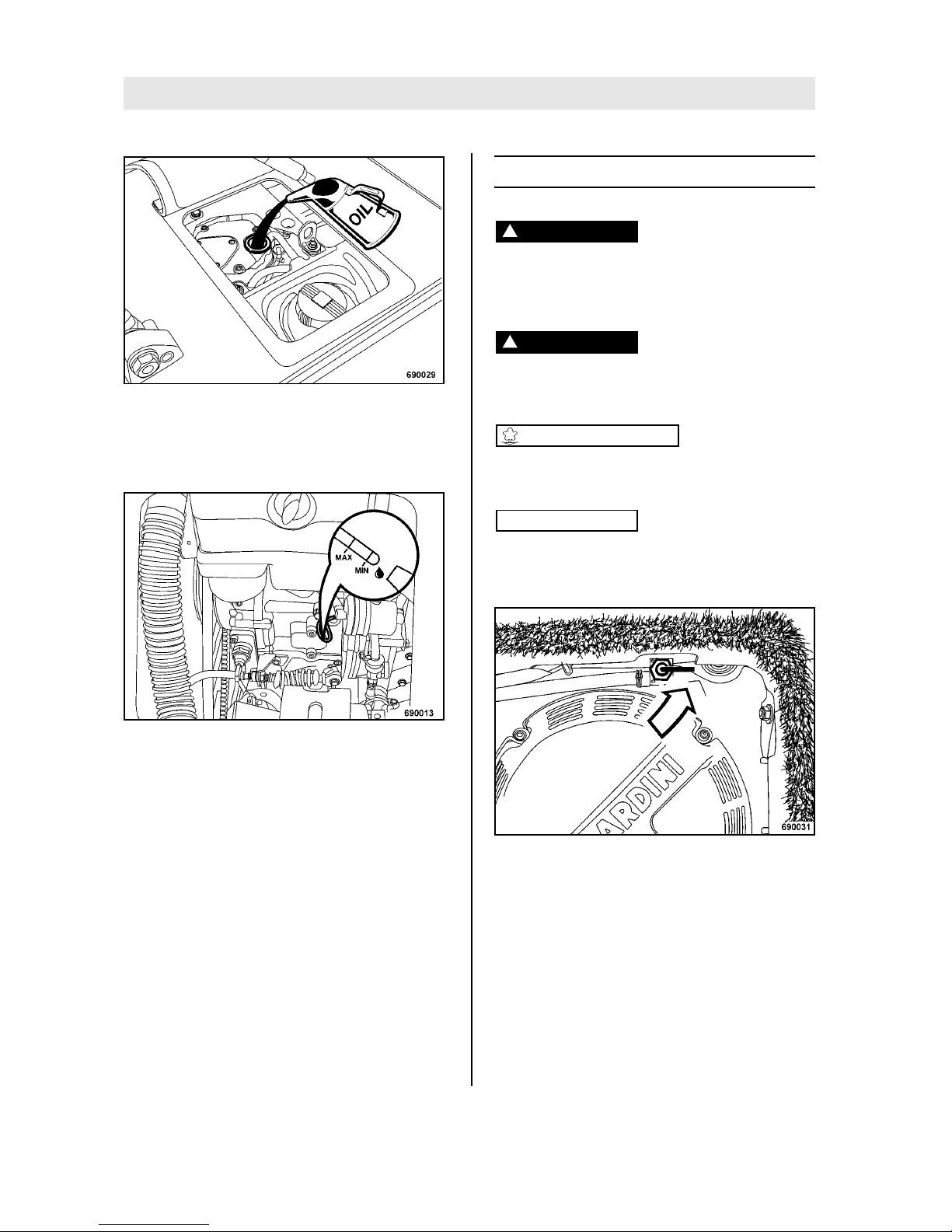
Fig. 60
l Fill in fresh engine oil through the filler opening
(Fig. 60).
l Screw the oil filler cap back on.
Fig. 61
l After a short test run check the oil level on the
dipstick (Fig. 61), correct the oil level as necessary.
6.16 Replacing the fuel filter
Danger!
Fire hazard!
When working on the fuel system do not use
open fire, do not smoke, do not spill any fuel.
Danger!
Health hazard!
Do not inhale any fuel fumes.
Environment
Catch running out fuel and dispose of environmentally together with the fuel filter.
Note
i
In case of contamination drain off and catch the
sludge from the fuel tank, flush out with clean diesel fuel.
Fig. 62
l Close the fuel tap (Fig. 62), set the handle to
horizontal position.
Page 55
Maintenance every year
BOMAG 55BPR 45/55 D, BPR 55/65 D
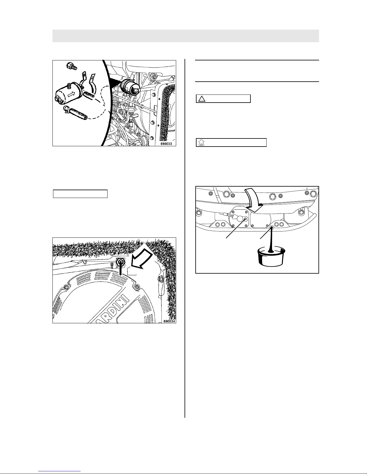
Fig. 63
l Loosen the hose clamps on the three fuel lines
and pul the fuel lines off the fuel filter (Fig. 63).
l Remove the bracket and take off the fuel filter.
Note
i
Mind the installation direction (arrow) when assembling the fuel filter.
l Install the new fuel filter, push on the fuel lines
and fasten them with the hose clamps.
Fig. 64
l Open the fuel tap (Fig. 64), set the handle to
vertical position.
6.17 Change the oil in the exciter
housing
Caution
!
Park the machine on level ground.
For quality and quantity of oil refer to the ”table of fuels and lubricants”.
Environment
Catch running out oil, do not let it seep into the
ground and dispose off environmentally.
l Clean the area around breather and drain
plug.
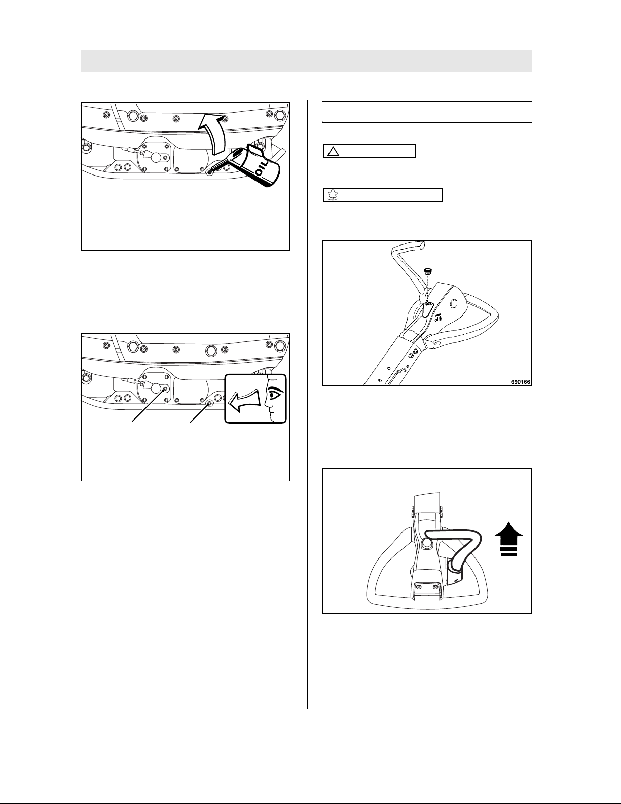
Fig. 65
l Unscrew ventilation (1) (Fig. 65) and level in-
spection plugs (2).
l Drain the oil through the inspection plug bore.
For this purpose tilt the machine to the side
with the oil drain opening and support it safely.
692081
OIL
1 2
Page 56
Maintenance every year
BOMAG56 BPR 45/55 D, BPR 55/65 D
Fig. 66
l Tilt the machine to the opposite side and se-
cure it properly.
l Fill in fresh oil through the level inspection
opening (Fig. 66).
Fig. 67
l Stand the machine on level ground and check
the oil level (Fig. 67).
The oil level must reach the bottom edge of the oil
level inspection bore.
l Clean level plug (2) and screw in with sealing
agent (e.g. BOMAG 009 700 16).
l Screw vent plug (1) tightly back in.
6.18 Check the hydraulic oil level
Caution
!
Park the machine horizontally.
Environment
Catch running out oil, do not let it seep into the
ground and dispose off environmentally.
Fig. 68
l Adjust the steering rod with height adjustment
(Fig. 68) so that the area with the level inspection plugs is horizontal.
l Unscrew the plug.
Fig. 69
l Hold the travel lever in forward position (Fig.
69).
692082
692080
1 2
692060
Page 57

Maintenance every year
BOMAG 57BPR 45/55 D, BPR 55/65 D
Fig. 70
l Check whether the hydraulic oil level is ap-
prox. 40 mm (1.6 in) below the filler opening
(Fig. 70) (see also mark on steering rod head),
top up hydraulic oil if necessary.
Filling up hydraulic oil
For quality and quantity of oil refer to the "table
of fuels and lubricants".
Fig. 71
l Shift the travel lever forward against the stop
(Fig. 71).
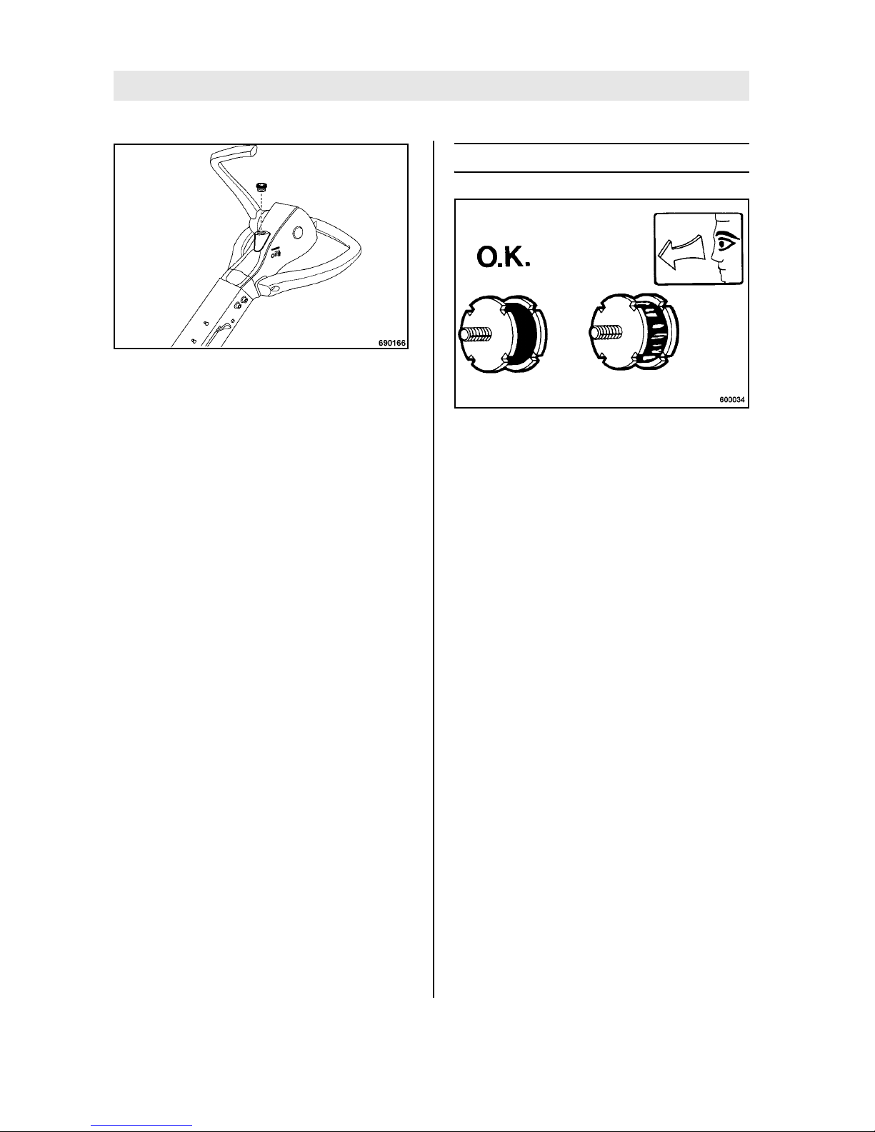
Fig. 72
Note
i
Lay a cloth down before loosening the venting
screw.
l Slacken the bleeding screw (Fig. 72).
l Wait until all air has escaped, then tighten the
bleeding screw.
Fig. 73
l Fill in hydraulic oil to approx. 40 mm (1.6 in)
below the edge of the filler opening (Fig. 73).
692060
Page 58
Maintenance every year
BOMAG58 BPR 45/55 D, BPR 55/65 D
Fig. 74
l Screw in and tighten the plug (Fig. 74).
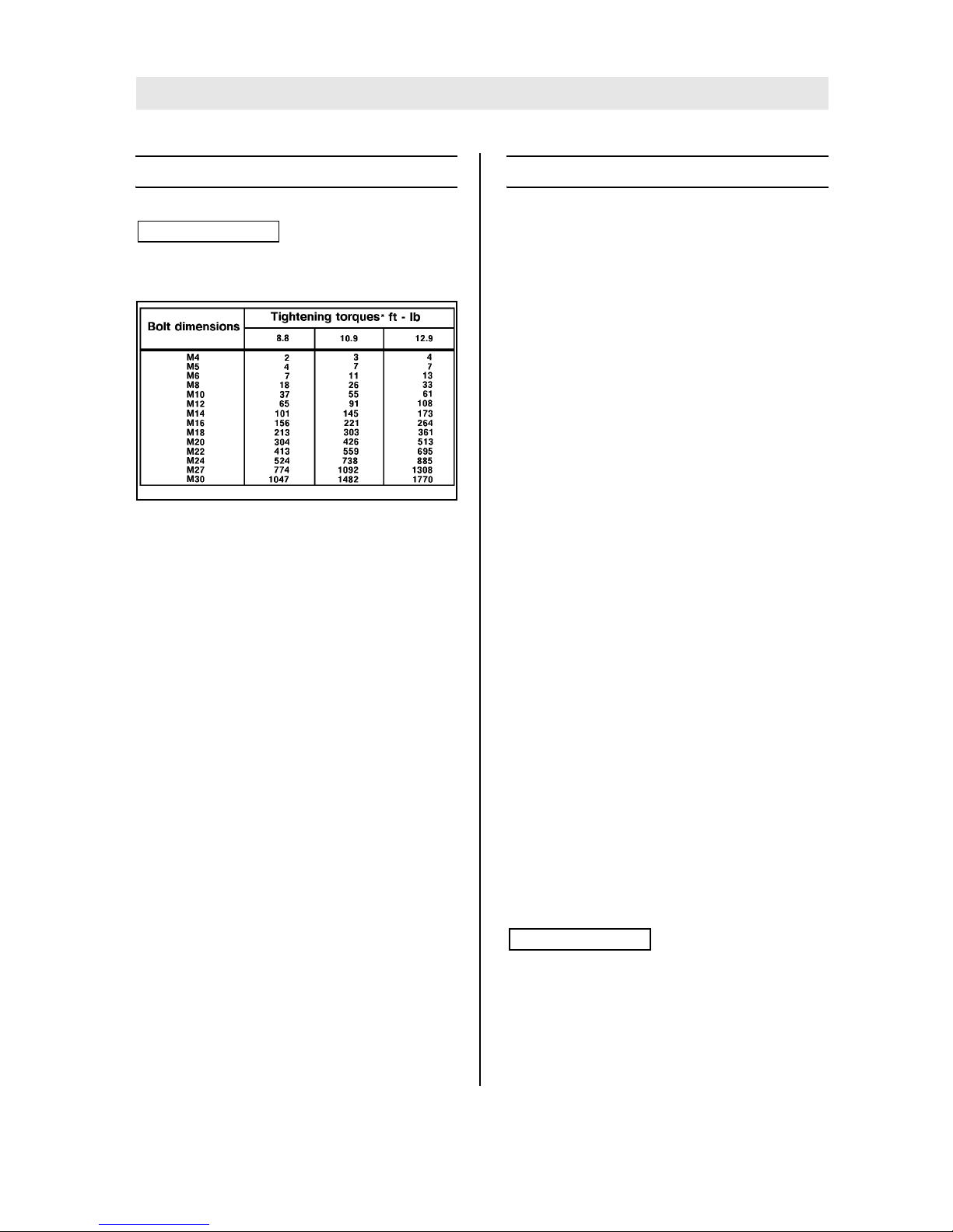
6.19 Check the rubber buffers
Fig. 75
l Check all rubber buffers (Fig. 75) for tight fit,
cracks and damage and replace immediately if
damaged.
Page 59
As required
BOMAG 59BPR 45/55 D, BPR 55/65 D
As required
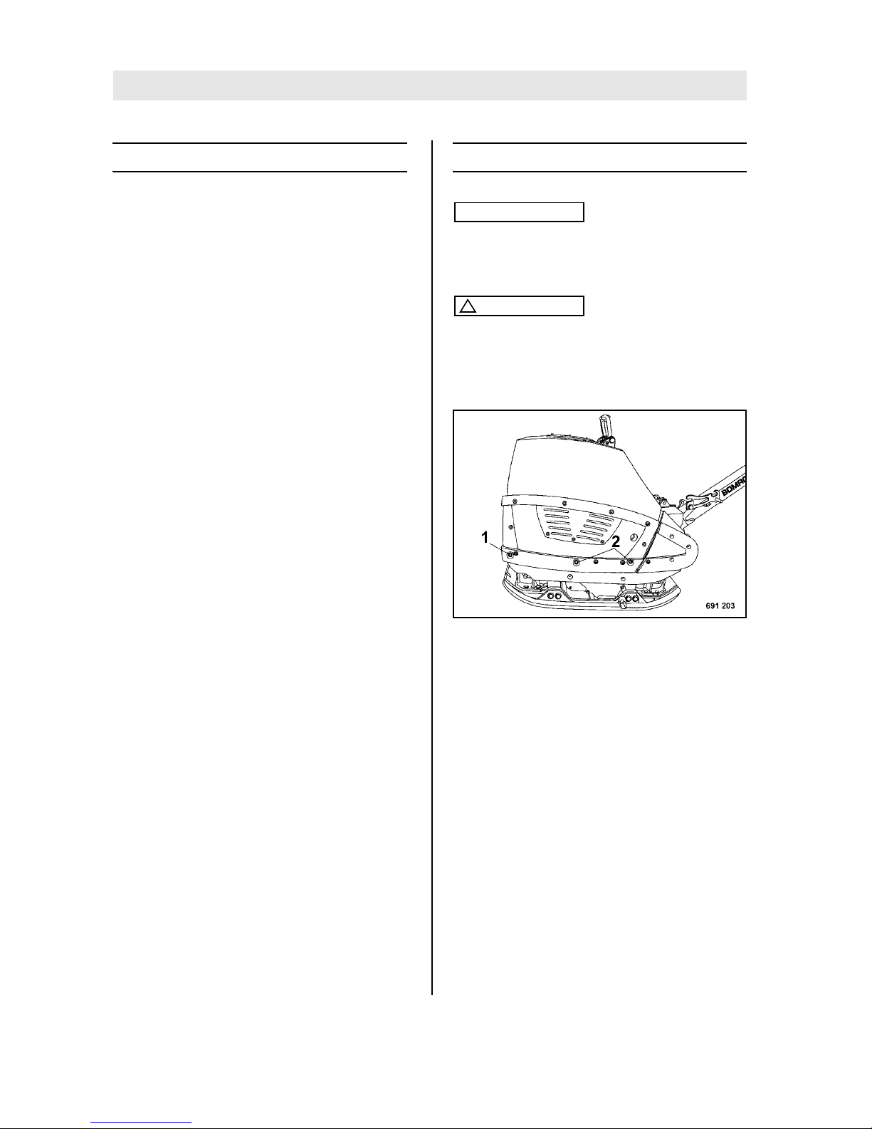
6.20 Tightening the screws
Note
i
Self locking nuts must always be replaced by new
ones after they have been unscrewed.
Fig. 76
*Strength classes for screws with untreated, nonlubricated surfaces. The quality designations are
stamped on the screw heads.
8.8 = 8 G
10.9 = 10 K
12.9 = 12 K
The values result in a 90% utilization of the screw's
yielding point at a coefficient of friction of μ total =
0.14.
The compliance with the tightening torques is to be
checked with torque wrenches.
The tightening torques are not applicable when using MoS
2
lubricants.
6.21 Engine conservation
If the engine is to be shut down for a longer period
of time (e.g. over winter), we recommend the following measures to avoid corrosion:
l Clean the engine: For this purpose use cold
cleansing agent or, even better, a steam
cleaner.
l Run the engine warm and shut it down.
l Drain the still warm engine oil and fill in anti-
corrosion engine oil.
l Change the fuel filter.
l Drain the fuel from the fuel tank, mix it well with
10% anti-corrosion oil and fill it back in. Instead of mixing the fuel with anti-corrosion oil
you may also fill the tank with injection pump
testing oil with anti-corrosive properties (e.g.
Calibration fluid B).
l Clean the air filter.
l Then run the engine for 10 minutes, so that
lines, filter, pump and nozzles are filled with
the conserving mixture and the new engine oil
is distributed to all parts.
l Remove the injection nozzle, spray the seat
with engine oil and reinstall the injection nozzle.
l Crank the engine several times to spray the
combustion chamber (throttle lever in stop position).
l Take the V-belt off and spray the grooves of
the V-belt pulleys with anti-corrosion oil. Remove the anti-corrosion oil before taking the
machine back into service.
l Close air intake on air filter and exhaust open-
ing tightly.
l Cover the engine and stand it on a wooden
pallet.
Note
i
Depending on weather conditions these conservation measures will protect the machine for approx.
6 to 12 months.
Before taking the machine back into service you
must drain off the conservation oil and replace it
Page 60

As required
BOMAG60 BPR 45/55 D, BPR 55/65 D
with engine oil (see table of fuels and lubricants)
according to API-(MIL-) classification.
Anti-corrosion oils are all oils which comply with
the specification MIL-L-21260 B or TL 9150-037/2
o Nato Code C640/642.
Caution
!
A machine with conserved engine must be
clearly marked by attaching a clear warning
tag.
Page 61

BOMAG 61BPR 45/55 D, BPR 55/65 D
7 Trouble shooting
Page 62
Trouble shooting
BOMAG62 BPR 45/55 D, BPR 55/65 D
7.1 General notes
Please observe strictly the safety regulations
in the corresponding section of these operating and maintenance instructions.
Malfunctions are frequently caused by incorrect
operation of the machine or insufficient maintenance. Whenever a fault occurs you should therefore thoroughly read these instruction on correct
operation and maintenance.
If you cannot locate the cause of a fault or rectify it
yourself by following the trouble shooting chart,
you should contact our customer service department.
7.2 Starting with jump wires
Note
i
Choose this type of starting if the starter battery is
flat and the machine cannot be started manually
with the recoil starter.
Caution
!
A wrong connection will cause severe damage
in the electric system.
The auxiliary battery must have the same voltage as the starter battery.
Fig. 77
l Loosen the hood fasteners (1) on both sides
and remove the fasteners (2) from both sides
(Fig. 77).
l Fold the hood back.
l Remove the battery holder and take off the vi-
bration damping mat.
l Check insulation mats, brackets and screw
connections, replace if necessary.
Page 63
Trouble shooting
BOMAG 63BPR 45/55 D, BPR 55/65 D
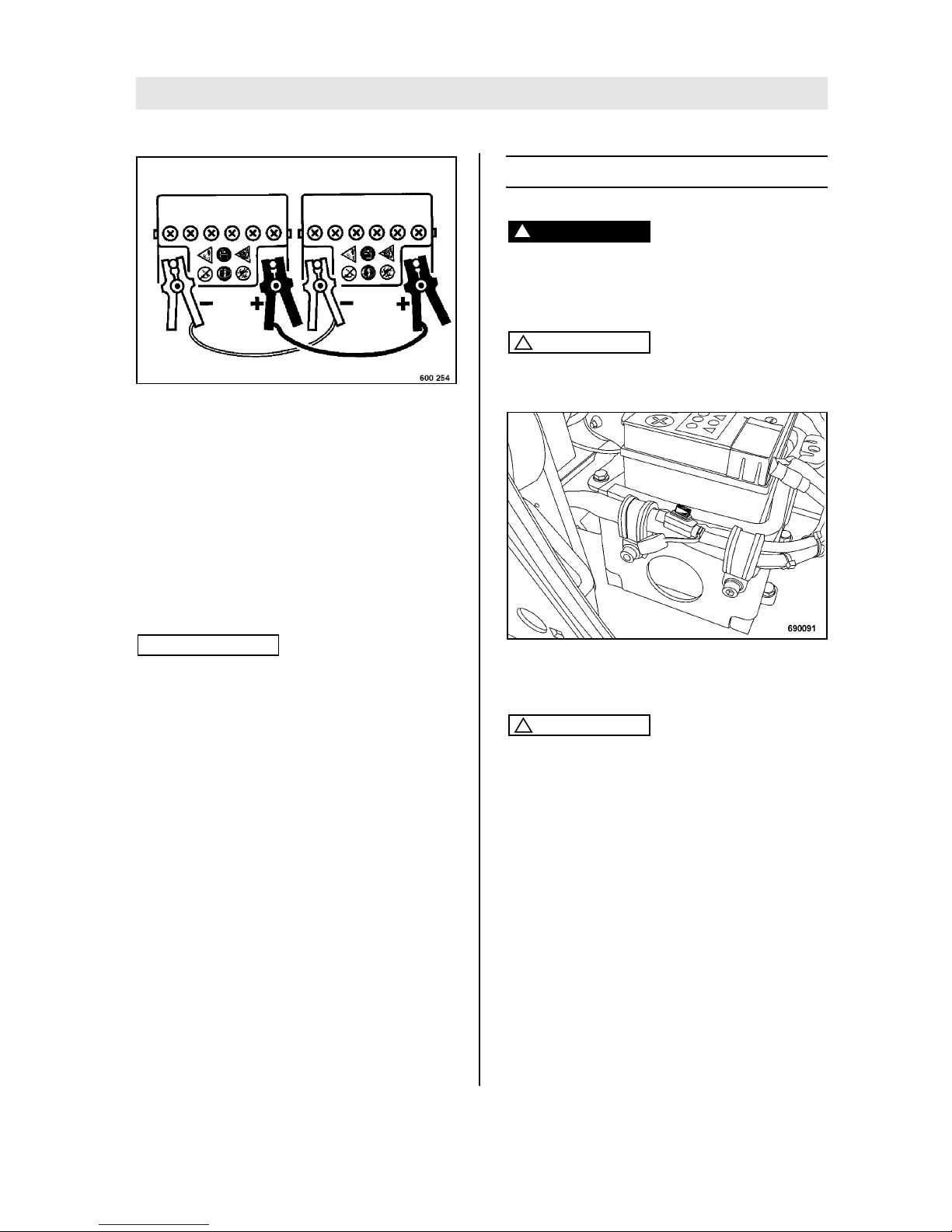
Fig. 78
l Join the plus poles on external battery and
starter battery with the jump wire (Fig. 78).
l Use the second jump start cable to connect
the negative poles on external battery and
starter battery.
l Start the engine as described in the chapter
“Starting the engine”.
l When the engine is running remove the jump
start cable from the two negative poles first
and from the positive poles after.
Note
i
This work sequence is necessary to avoid short
circuit caused by contact between positive and
negative cables.
l Close the hood again and ´fasten it with bolts.
7.3 Fuses
Danger!
Fire hazard!
Do not use fuses with higher ampere ratings
and do not bridge fuses.
Caution
!
Always cover the fuse with the protective cover.
Fig. 79
Fuse (25 A) (Fig. 79).
Caution
!
Machines with Economizer1 are protected by
an additional fuse (5 A).
1 Optional equipment
Page 64

Trouble shooting
BOMAG64 BPR 45/55 D, BPR 55/65 D
7.4 Engine problems
Fault Possible cause Remedy
Engine does not
start or does not
start immediately, but can be
cranked with the
starter motor
Throttle lever in stop or idle speed position.
Set the lever to “Start” position.
No fuel at the injection pump. Fill in fuel
Check the entire fuel system systematically.
Insufficient compression
- incorrect valve clearance Check, adjust the valve clearance.
- Wear on cylinder or piston rings Have examined by a specialist.
Injection nozzle out of order Have examined by a specialist.
Additionally on
engines with
mechanical oil
pressure monitoring
No oil pressure Check the oil level.
Activate mechanical oil pressure monitoring
With low temperatures
Temperature below starting limit. Observe cold start instructions.
Fuel gelled because of insufficient cold
compatibility.
Pull the fuel hose off the fuel lift pump and
check whether fuel runs out of the fuel
pump clear and without gel.
In case of gelled fuel you should either
warm the engine up or drain the complete
fuel supply system.
Fill with a temperature resistant fuel mixture.
Starter speed too low:
- Oil with too high viscosity Replace engine oil with oil of correct viscosity
- Insufficiently charged battery Check the battery, if necessary consult a
specialist workshop
The starter is not
switched on or
the engine does
not crank
Fault in the electric system:
- Fuse defective
Check electric equipment and related
components or consult the our customer
service.
- Battery or other cable connections not
correctly connected.
- Cable terminals loose or oxidised
- Battery defective or not charged
- Starter defective
- Insufficiently charged battery
Page 65

Trouble shooting
BOMAG 65BPR 45/55 D, BPR 55/65 D
Engine ignites,
but does not
continue to run
when switching
the starter motor
off.
Fuel filter clogged. Replace the fuel filter.
Fuel supply interrupted. Check the entire fuel system systemati-
cally.
Stop signal from monitoring elements
connected with the oil pressure monitoring facility:
- no oil pressure Check the oil level.
Engine shuts
down by itself
during operation
Tank empty. Fill in fuel.
Fuel filter clogged. Replace the fuel filter.
The mechanical oil pressure monitoring
shuts the engine down because of a lack
off oil
Check the oil level, activate the oil pressure monitoring system.
Mechanical defects.
Engine looses
power and
speed
Fuel supply restricted:
- Tank empty Fill in fuel, activate the mechanical oil
pressure monitoring system.
- Fuel filter clogged Replace the fuel filter.
- Insufficient tank ventilation Ensure sufficient ventilation of the tank.
- Line connections leaking Check line connections for leaks.
Throttle lever does not stay in selected
position.
Block the throttle control.
Too much oil in crankcase. Drain off oil.
Engine looses
power and
speed, black exhaust smoke
Air filter dirty. Clean or replace the air filter.
Incorrect valve clearance. Adjust the valve clearance.
Injection nozzle out of order Have examined by a specialist.
Engine overheating
Too much oil in engine. Drain the engine oil down to the top mark
on the dipstick.
Insufficient cooling:
- Dirt in the entire area of the cooling air
flow
Clean the cooling air area.
- Air guide plates not completely closed. Check air guide plates for completeness
and good sealing
Fault Possible cause Remedy
Page 66

Trouble shooting
BOMAG66 BPR 45/55 D, BPR 55/65 D
7.5 Trouble shooting Economizer
Fault Description Possible cause
Status-LED off Operation
Status-LED on no frequency detected Engine not running
Plug-in connector defective
Sensor/cable defective
Status-LED
flashing
Frequency detected, but outside permissible range
Engine speed too low
Vibration frequency too low
Sensor defective
atypical soil
V-belt slipping
incorrect V-belt installed
Page 67

BOMAG 67BPR 45/55 D, BPR 55/65 D
8Disposal
Page 68

Disposal
BOMAG68 BPR 45/55 D, BPR 55/65 D
8.1 Final shut-down of machine
If the machine can no longer be used and needs to
be finally shut down you must carry out the following work and have the machine disassembled by
an officially recognized specialist workshop.
Danger
!
Danger of cauterisation ! Danger of explosion!
When working on the battery do not use open
fire, do not smoke!
The battery contains acid. Do not let acid come
in contact with skin or clothes!
Wear protective clothing!
l Remove the batteries and dispose of in com-
pliance with legal regulations.
Environment
Catch all fuels and lubricants, do not let them
seep into the ground and dispose of in compliance with legal regulations.
l Empty the fuel tank.
l Drain lubrication oil from engine and exciter
housing.
l Drain off hydraulic oil.
Danger
!
Danger of explosion!
Parts that previously contained combustible
fluids must not be cut with a cutting torch.
Page 69
Page 70
 Loading...