

Page 1
Orion ISS
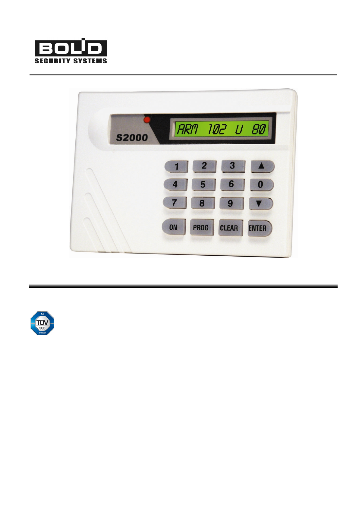
KEYPAD
S2000-K
User’s Manual
Page 2

This User’s Manual is intended to help for studying operability principles and maintenance of the
S2000-K Keypad of versions 1.04 and above.
Please read the instructions completely before connecting, operating, adjusting, or maintain-
ing this product.
The following terms are used throughout the Manual:
Alarm Loop (or Loop, or LP): The electrical circuit with non-addressable fire or intrusion detectors
(or other non-addressable devices) included. Actuation of a single detector brought in an alarm
loop causes breaking of the loop as a whole, so the actuated detector can be located only with
the accuracy of the alarm loop
Zone: A minimal part of a security and safety installation that can be monitored and controlled inde-
pendently. Depending on the context, the term ‘zone’ can imply an alarm loop, an addressable
detector, a hardwire component, etc.
Partition: A set of zones that can be user controlled as a whole. As a rule, zones fall into partitions
depending on their location (e.g., one partition can involve all zones at one individual area)
Arm/Disarm means starting/cancellation monitoring of a loop (zone, partition, system) conditions and
signaling alarms in controlled zones
Network Address (Address): The unique number of a device (ranged from 1 to 127) within the Orion
local RS-485 network
Page 3

S2000-К
Table of Contents
Features and Design..............................................................................................................5
Specifications ........................................................................................................................9
Operating..............................................................................................................................11
Indication ..................................................................................................................................12
Access Requests ......................................................................................................................13
Arming and Disarming ..............................................................................................................15
Partition Arming Procedure 16
Partition Disarming Procedure 17
Reviewing System Events and Processing Alarms ...................................................................18
Keypad Operations Summary ...................................................................................................20
Transmitting S2000-K Events to the Network Controller ...........................................................21
Installation............................................................................................................................23
Mounting...................................................................................................................................24
Wiring .......................................................................................................................................25
Connecting the Orion RS-485 Interface Bus 25
Connecting the Power Supply 25
Getting Started..........................................................................................................................26
Programming .......................................................................................................................27
Programming the Keypad .........................................................................................................28
Programming the Network Address of the S2000-К 29
Programming the S2000-K to Display Events and Indicate Alarms 30
Network Controller Settings ......................................................................................................31
How to enroll the S2000-К to the Console Database Using PProg 31
Programming the Console for Receiving Commands from the Keypad 32
Programming the Mechanism of Translating Events 34
Maintenance ......................................................................................................................... 41
Troubleshooting........................................................................................................................42
Inspection .................................................................................................................................43
S2000-K Testing Procedure 44
Appendix System Events Displayed by the Keypad LCD.................................................. 45
3 www.bolid.com
Page 4

Orion ISS
www.bolid.com 4
Page 5

S2000-К Features and Design
FEATURES AND DESIGN
5 www.bolid.com
Page 6

Orion ISS
The S2000-K keypad is designed to operate as the part of an Orion Integrated Security System (ISS)
which enables users to be authenticated via their PIN codes / access devices and to input author-
ized commands to control various functions of the security system, including:
Ø Observing current statuses of specified system partitions
Ø Arming specified system partitions
Ø Disarming specified system partitions
Ø Limited access into protected premises
The S2000-К keypad is connected to a system interface RS-485 and works under control of an Orion
ISS network controller which can be an S2000 / S2000М / S2000L fire and alarm console of version
1.10+ or a personal computer under Orion software.
User pre-registered four-digit PIN codes (or passwords) and control commands are typed on the
S2000-К keypad. The S2000-K keypad then transfers entered passwords and commands via the RS-
485 interface to the network controller which analyzes the received data, makes decisions to grant or
deny access to the requested operations, send relevant commands to for control and indicating
equipment and executive devices. The results of processing user requests are returned to the key-
pad. The dialog between the network controller and a user as well as a result of performing opera-
tions are displayed on the S2000-K LCD. Users can also be authenticated by means of access de-
vices such as Touch Memory devices (DS iButtons) or Proximity cards pre-registered by the network
controller and presented to one of the Orion ISS readers. After a user has been authenticated all ac-
tivities permitted to him are carried out by operating with the S2000-К keypad.
The S2000-К keypad can be used also as an output device for indicating events occurring in the
Orion system. In this mode the messages received by the keypad from the network controller via RS-
485 interface are displayed in textual form on the S2000-K LCD. Also these messages are written into
the S2000-K non-volatile memory (up to 255 messages) and are available to be reviewed. Receiving
alarm messages can be accompanied by the S2000-K light indication and sounding.
The S2000-К is equipped with a tamper switch, so it transmits the network controller the Tamper
Alarm and Tamper Restored messages as well as messages about resetting the keypad. In the case
when communications with the network controller via RS-485 interface is temporary lost such mes-
sages are stored in the keypad non-volatile memory (up to 16 messages). When communication is
restored, these messages are sent to the network controller with actual event time in accordance with
the internal S2000-K clock.
The S2000-К keypad is to be used in the locations protected against atmospheric precipitation and
mechanical damage, and is intended for continuous round-the-clock performance. The S2000-К de-
www.bolid.com 6
Page 7
S2000-К Features and Design
sign does not provide usage in presence of aggressive media, dust, and also in fire-hazardous spac-
es.
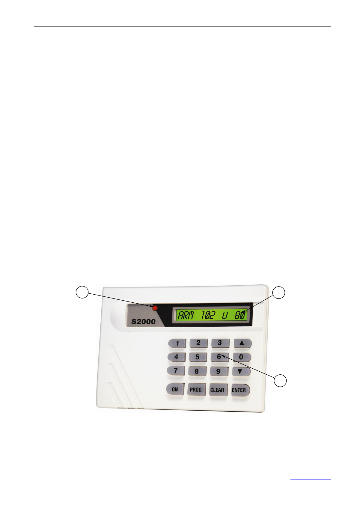
The S2000-К keypad is equipped with the green backlit liquid crystal display (LCD), 1 x 16 characters
(2). In the quiescent mode the display indicates current time. In the User Command Input mode the
LCD displays the dialog between the user and the network controller as well as a result of the re-
quested operations while when the keypad is used as output device the LCD displays the messages
received from the network controller.
The S2000-K keypad being in the Event Display mode, its LED indicator (1) indicates the fact of re-
ceiving a message from the network controller by steady lighting. If, in addition, the mode of indicating
alarms is set on the LED indicates raw alarms by blinking.
The buttons (3) are used to input user commands, to switch the keypad LCD into display modes (see
above), to browse event log records, and to clear alarm messages.
The S2000-К has a built-in beeper for indicating pressing the buttons and the results of performed
operations. In the alarm indication mode the beeper produces differentiated beeps depending on the
message content.
The non-volatile memory is intended to store the network address of the keypad, the keypad configu-
ration parameters, the keypad event buffer, and the system message log.
7 www.bolid.com
Page 8

Orion ISS
www.bolid.com 8
Page 9

S2000-К Specifications
SPECIFICATIONS
Ø 16 backlit buttons
Ø 16-character backlit LCD
Ø Non-volatile event log for storing last 255 received events
Ø Light and Sound Alarm Indication
Ø Non-volatile event log for storing last 16 keypad events
Ø Input Voltage 10.2 ÷ 28.4 VDC
Ø Consumed Current
Ø Operating Temperatures
Ø Overall Dimensions
Ø Enclosure Material
50 mA @ 12 VDC or 25 mA @ 24 VDC
+1 °С to +40 °С
146 ´ 105 ´ 35 mm
Plastic
9 www.bolid.com
Page 10

Orion ISS
www.bolid.com 10
Page 11

S2000-К Operating
OPERATING
11 www.bolid.com
Page 12

Orion ISS
INDICATION
S2000-К indication is realized by means of the LCD, the LED indicator, and the audible sounder
(beeper).
The S2000-К LCD can work either in the quiescent mode (also called the Time Display mode), or in
the Command Input mode when the dialog between a user and the system is carried out, or in the
Event Display mode when the S2000-K displays system messages received from the network control-
ler (if the last option is set).
In the quiescent mode the LCD of the S2000-K displays the current time, and the LED indicator and
beeper are turned off.
When the S2000-К is configured to output system messages, the keypad displays these messages on
the LCD screen upon receipting them from the network controller and turns on the LED indicator. To
switch from the Event Display mode into the Time Display mode, press the CLEAR button.
Moreover, if communications between the keypad and the network controller is lost, the S2000-К LCD
displays the message “COMMUNICATIONS LOST” and the keypad LED flashes once per second. In
such a case all user operations with the keypad S2000-K (i.e. typing a password, observing mes-
sages, and requesting access) become unavailable.
In the quiescent mode the S2000-К beeper is turned off. Pressing the buttons on the keypad is ac-
companied by short single beeps. To indicate the results of operations such as an access request or
arming system partitions the beeper has two special beeps:
Success Two short beeps
Error Long single beep
While the S2000-К is operating in the Indicate Alarms mode the beeper is used for indication of alarm
messages (see below). To reset the alarm beep it is necessary to press any button.
The S2000-К LED indicator accompanies messages received from the network controller (if this
mode is set), or indicates loosing connections with it.
No communication via RS-485 Flashes once per second
No messages Off
A message is received Lit steady
An alarm message is received Blinks
www.bolid.com 12
Page 13

S2000-К Operating
ACCESS REQUESTS
When the S2000-К keypad is used in an access control system, to request access into protected
premises it is necessary to enter four-digit password (PIN code) which must be registered by the net-
work controller with appropriate privileges. User identification can be made also by means of a Touch
Memory device (iButton) or Proximity card registered by the network controller with appropriate privi-
leges and presented to one of the Orion ISS reader which is assigned to this S2000-K keypad (see
the Network Controller Setting section of this Manual).
For authenticators (that is, electronic access devices and contactless cards) that give the rights of
passage through several access points it is necessary to specify the number of the door which is to
be opened.
If the presented authenticator is recognized by the network controller and gives access rights for pas-
sage through the specified door, the S2000-К displays the ACCESS GRANTED message, and the
network controller sends a command for the relevant executive device to unlock the door.
Otherwise the S2000-К gives an Error signal and displays an access reject message with specifying
one of the reasons as follows:
ILLEGAL CODE The authenticator presented is not registered by the network controller
ACCESS DENIED The authenticator presented has no authorities to gain access via the
specified door or access is blocked for this one
WRONG PARTITION The authenticator presented has no authorities to gain access to the
specified partition
FAILED Command run error
Requesting access is carried out from the S2000-K quiescent mode, which can be reached if neces-
sary by pressing the CLEAR button. Examples of access request using the S2000-K keypad are giv-
en below.
Request with the Rights to Access through a Single Door
ENTER CODE:
Switch the S2000-К if necessary into the Time Display mode (see
above) and type your four-digit password on the S2000-K keypad
(or present your electronic access device to a reader which is
assigned to this S2000-K).
ACCESS GRANTED
In success case the positive access message will be displayed on
the S2000-K LCD, and the beeper will produce the Success signal.
Otherwise, the beeper will produce the Error audible signal, and an
access reject message will be indicated by the display.
After thrice-repeated entering of invalid passwords the keypad
blocks input for 30 seconds.
13 www.bolid.com
Page 14
Request with the Rights to Access through Several Doors
Orion ISS
ENTER CODE:
vDOOR:ХХХХ
ACCESS GRANTED
Switch the S2000-К, if necessary, into the Time Display mode (see
above) and type your four-digit password on the S2000-K keypad
(or present your electronic access device to a reader which is
assigned to this S2000-K).
If the entered password (presented access device) is registered in
the system and has the relevant access rights, the number of one of
the doors accessible to the user will be represented on the LCD.
Using buttons t and u, select the necessary door number or type
it (from 1 to 9999) by number buttons, and then press ENTER.
In case of success the positive access message will be displayed on
the S2000-K LCD, and the beeper will produce the Success signal.
Otherwise, the beeper will produce the Error audible signal, and an
access reject message will be indicated by the display.
After thrice-repeated entering of invalid passwords the keypad
blocks input for 30 seconds.
www.bolid.com 14
Page 15

S2000-К Operating
ARMING AND DISARMING
If the S2000-К keypad is used in a fire and intruder alarm Orion system for authorized arming and/or
disarming specific system partitions, to execute a required operation it is necessary to enter four-digit
user password (PIN code) from the keypad or present the appropriate electronic access device to a
reader which is assigned to this S2000-K keypad. The password or access device should be regis-
tered by the network controller along with a list of partitions authorized for controlling by the given
user and a range of permitted operations such as arming, disarming, both arming and disarming, or
only observing statuses (see the Section Network Controller Setting of this Manual).
If the presented password (or access device) has dual function in the system and is used also for ac-
cess into fixed premises, for switching the keypad into partition control mode before input of the
password (presenting electronic access device) it is necessary to press the ON button (inputting the
password without pressing the ON button in this case will initiate an access request).
After the correct password (electronic access device) is presented, status of one of the user accessi-
ble partitions is represented on the S2000-K display. The partitions can be in following statuses:
DISARMED The partition is disarmed
DISARMING… The partition is being disarmed at the time
ARMED The partition has been armed and being in Norm
ARMING... The partition is being armed at the time
ARMING FAILED The partition failed to be armed
FAULT A fault has been occurred in the partition such as open or short failure in a
some zone
DISCONNECTED Communications with some zones of the partition is lost (e.g., no communica-
tions via RS-485 with the device whose zones are included into the partition)
INTRUSION
ALARM
An Intrusion Alarm in the partition
PANIC ALARM A Panic Alarm in the partition
FIRE PREALARM Fire is supposed to be in the partition
FIRE ALARM There is fire in the partition
15 www.bolid.com
Page 16

Orion ISS
Arming and disarming are executed when the S2000-K is in the current time display mode, which can
be reached, if necessary, by pressing the CLEAR button. Examples of arming/disarming procedures
using the S2000-K keypad are given below.
Partition Arming Procedure
ENTER CODE:
v 1200: DISARMED
Switch the S2000-К, if necessary, into the current time display mode
(see above). If the presented authenticator is intended not only to
arm/disarm but also to gain access, press the ON button to switch
the display to the Command Input mode. Type four-digit user
password on the S2000-К keypad or present your electronic access
device to a reader which is assigned to this S2000-K keypad.
If the entered password is not identified by the network controller,
the S2000-K produces the Error beep and displays the ILLEGAL
CODE message followed by switching into the Time Display mode.
After thrice-repeated entering of invalid passwords the keypad
blocks inputting password for 30 seconds.
If the password (access device) is correct, the keypad displays a
status of the first partition accessible to the user (see above). The
example shows partition 1200 being in DISARMED status.
To review the statuses of all accessible partitions scroll the list using
the t and u or type numbers of the required partitions using the
relevant S2000-K buttons.
vARM
ARM FAIL 003/010
To arm a partition select it number from the list using the t and u
buttons or enter the number by the keypad numeric buttons, and
then press ENTER.
Menu vARM will appear on the display.
Using the t and u buttons select vARM or vDISARM (if the
user has no rights for arming or disarming, the appropriate menu will
be unavailable). Select vARM and press ENTER.
If arming was successful, the S2000-K produces the Success beep
and displays the new partition status: v1200: ARMED.
Otherwise, the S2000-К will produce the Error beep and display an
error message such as WRONG PARTITION, FAILED or ARMING
FAILED.
In the showed case the zone 003/010 is not armed. Here the 003 is
for the device address into the RS-485 interface and the 010 is the
number of the device’s alarm loop which arming has appeared to be
unsuccessful.
www.bolid.com 16
Page 17

S2000-К Operating
Using the t and u buttons, it is possible to review if there are
other non-armed zones in the partition.
To return the display back to indicate the partition status and to
proceed to the other partitions press CLEAR or ENTER.
Partition Disarming Procedure
ENTER CODE:
v 1200: ARMED
Switch the S2000-К if necessary into the Time Display mode. If the
presented authenticator is intended not only to arm/disarm but also
to gain access, press the ON button to switch the display to the
Command Input mode. Type four-digit user password on the S2000К keypad or present your electronic access device to a reader which
is assigned to this S2000-K keypad.
If entered password (presented access device) is not identified by
the network controller, the S2000-K produces the Error beep and
displays the ILLEGAL CODE message followed by switching to the
Time Display mode. After thrice-repeated entering of invalid
passwords the keypad blocks password inputting for 30 seconds.
If the password (electronic access device) is correct, the keypad
displays the status of the first partition accessible to the user. The
example shows the 1200 partition being in the ARMED status.
Select the proper partition using t and u buttons or enter the
number by the keypad buttons, and then press ENTER.
vDISARM
To disarm the partition select vDISARMING from the command
menu and press ENTER.
If partition disarming was successful, the keypad produces the
Success beep and displays the new partition status:
v1200: DISARMED. In case of negative result the keypad will
produce the Error beep and display an error message such as
WRONG PARTITION or FAILED.
17 www.bolid.com
Page 18
Orion ISS
t
t
t
t
t
REVIEWING SYSTEM EVENTS AND PROCESSING ALARMS
The Event Display mode and the Indicate Alarms mode (for the messages received from the network
controller) are optional and should be set specially while configuring the system (see the Section
Programming the S2000-K to Display Events and Indicate Alarms of this Manual). For such the
modes the LCD of the keypad displays defined for this keypad messages about the events of certain
type occurred in specified partitions of the Orion system such as arming and disarming zones and
partitions, alarms, faults, etc. (the full list of supported messages is given in the Appendix to this Man-
ual).
A message from the network controller is displayed on the keypad LCD for 15 seconds, being accom-
panied by turning on the LED indicator, and then the display switches into the Time Display mode. If
two or more messages are received simultaneously, the keypad displays them consistently during a
second each, the last message being displayed for 15 seconds. For forced exit into the Time Display
mode it is necessary to press CLEAR.
The last 255 received messages are stored in the S2000-К non-volatile memory. The buttons t and
u are intended to browse the message log, with scrolling messages in direct chronological order be-
ing executed by the t button, and scrolling in reverse order being executed by the u button. To re-
view the time of message delivery press and hold the 000 button.
If the Display Events mode and the Indicate Alarms mode are set on (see the Programming the
S2000-K to Display Events and Indicate Alarms section of this manual), then receiving an alarm mes-
sage from the network controller causes the S2000-K keypad to turn its LED indicator on in blinking
mode, output the message on the display and turn on the beeper (except the PANIC ALARM mes-
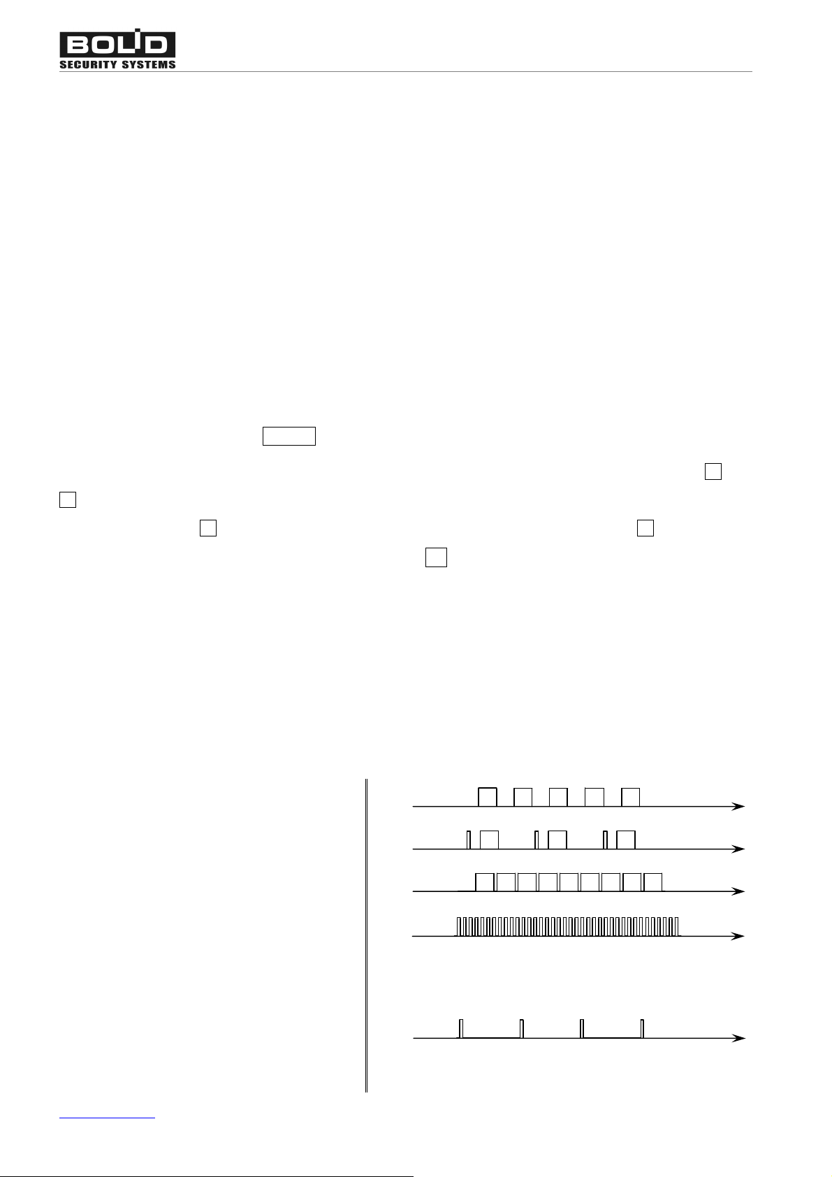
sage). The type of a sound signal (the supported sound patterns are showed below) allows the opera-
tor to identify the alarm message type. The sound signal can be stopped by pressing any S2000-K
button.
INTRUSION ALARM
FIRE PREALARM
FIRE ALARM
TAMPER ALARM
LOOP DISCONNECTED
DEVICE RESET
COMMUNICATIONS LOST
LOOP SHORT FAILURE
LOOP OPEN FAILURE
POWER FAILED
www.bolid.com 18
Page 19

S2000-К Operating
To confirm receiving of an alarm message, press the ENTER button. After that the alarm is consid-
ered to be accepted, the LED indicator turns off, and the display switches into the Time Display mode.
The alarm message also can be dropped from the display using the CLEAR button. In the last case
display also switches into the Time Display mode, but message reception is considered to be not con-
firmed, and the LED indicator continues to work in blinking mode. To process the alarm messages (to
confirm receiving) from the Time Display mode press ENTER, and then by means of t and u but-
tons select the required message and confirm its reception by repeated pressing of the ENTER but-
ton.
NOTE! Processing alarms by means of the S2000-K keypad means only confirmation of their receiv-
ing by the operator and does not change a status of the alarm system: when an alarm is “unset” by
the S2000-K operator, the actual system zone keeps being in the alarm status as well as resetting
alarms in the alarm system does not lead to resetting this alarm for the S2000-K.
The alarms, unlike other messages (provided that the alarm indication mode is set for the S2000-K)
are displayed by the S2000-K up to an operator response (CLEAR or ENTER) or until the S2000-K
keypad receives a next alarm message with the same or higher alarm level. If several alarm mes-
sages are received by the S2000-K keypad at the same time, a message with the highest alarm level
is displayed. The main groups of messages in ascending alarm level order are shown below:
ARMING FAILED (the minimum priority)
LOOP SHORT FAILURE, LOOP OPEN FAILURE, POWER FAILED
(a local fault)
DEVICE RESET, TAMPER ALARM, DEVICE-TO-CONTROLLER COMMUNICATIONS LOST
(a fault or sabotage)
INTRUSION ALARM
PANIC ALARM (DURESS ALARM)
FIRE PREALARM
FIRE ALARM (the maximum priority)
19 www.bolid.com
Page 20
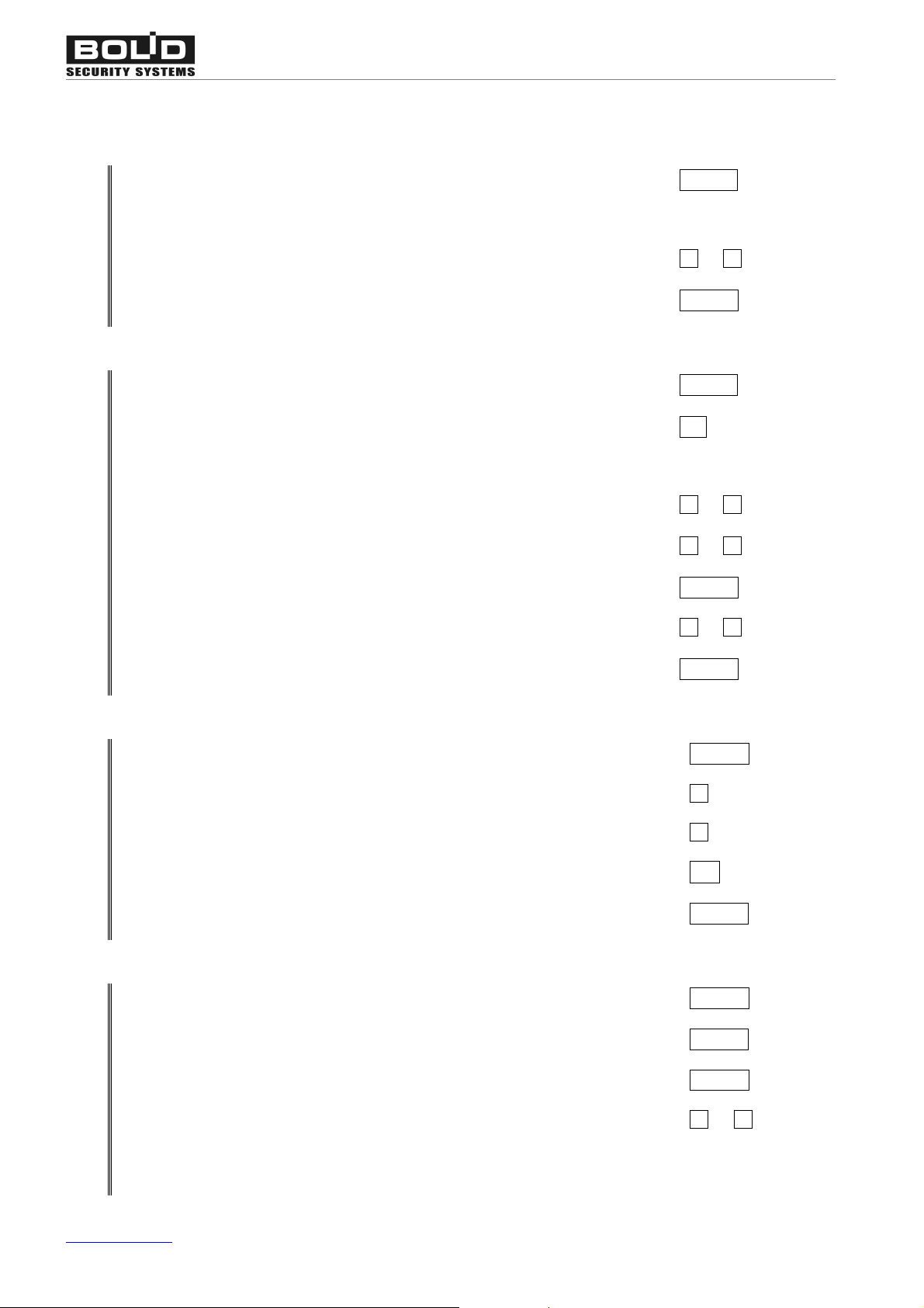
KEYPAD OPERATIONS SUMMARY
Requesting Access
Orion ISS
Switch the S2000-K display to the Time Display mode (if necessary)
Type your password (or present your access device)
s
Select the proper door from the list of available ones
Request access via the selected door
Arming/Disarming
Switch the S2000-K to the Time Display mode (if necessary)
Turn arming / disarming on (if necessary)
Type your password (or present your access device)
Review statuses of available partitions
s
Select the relevant partition from the list of available ones
Enter the arming / disarming menu
Select the command (if available)
CLEAR
t or u, or a door #
ENTER
CLEAR
ON
t or u
t or u, or a door #
ENTER
t or u
Confirm the selected command
Reviewing System Messages
Review the event log
Browse the event log forward (from the Time Display mode)
s
Processing Alarms
s
Browse the event log backward (from the Time Display mode)
View message time
Switch the LCD to the Time Display mode
Confirm receiving an alarm
Drop the alarm without confirmation
Process alarm (if there are raw alarms)
ENTER
ENTER
t
u
000
CLEAR
ENTER
CLEAR
ENTER
Observe the list of alarms
Stop sounding Press a key
www.bolid.com 20
t or u
Page 21

S2000-К Operating
TRANSMITTING S2000-K EVENTS TO THE NETWORK CONTROLLER
The S2000-K keypad automatically transmits the network controller which this one is connected to the
messages about its current status such as:
DEVICE RESET
TAMPER ALARM The device enclosure has been open
TAMPER RESTORED The device enclosure has been closed
The keypad provides buffering of events that should be transmitted to the network controller via RS-
485 interface in case of communication loss. After a minute since an event has occurred but not
transmitted the event is assigned to a time in accordance with the internal keypad clock. The event
buffer capacity is 16 events.
21 www.bolid.com
Page 22

Orion ISS
www.bolid.com 22
Page 23

S2000-К Installation
INSTALLATION
23 www.bolid.com
Page 24
There are no potential hazard electrical circuits within the S2000-К.
95
3
5
Do SHUT OFF the keypad power before wiring and maintaining the S2000-K
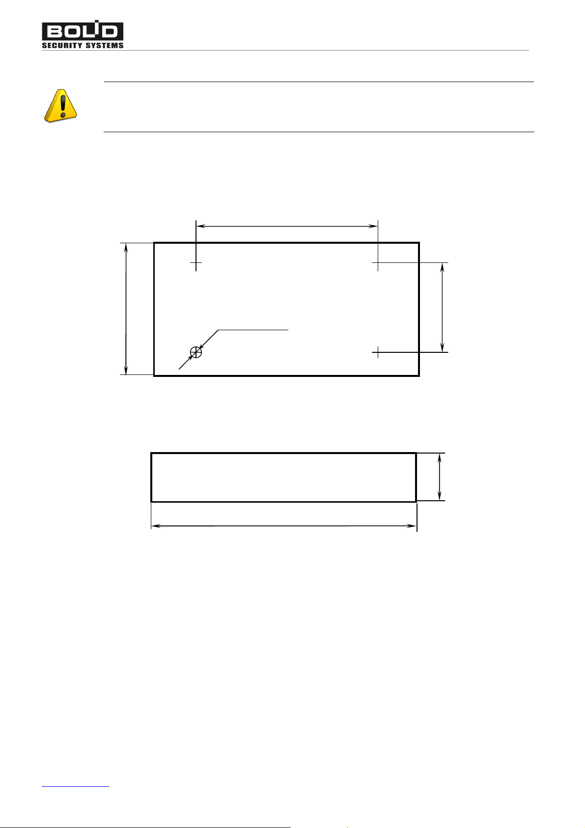
MOUNTING
Orion ISS
105
4 holesÆ 4
146
Figure 1. S2000-K Overall and Mounting Dimensions
65
The S2000-K is to be mounted on walls or other constructions within the premises which are pro-
tected against atmospheric fallouts, mechanical damage, and unauthorized access.
Select the mounting location that is to be approximately 1.5 m above the floor.
The S2000-K overall and mounting dimensions are shown in Figure 1.
www.bolid.com 24
Page 25
S2000-К Installation
+ U
0
V
S
2000
-
К
BA43+ U
0V2
1
XT1.1
XT1.2
RS-485
WIRING
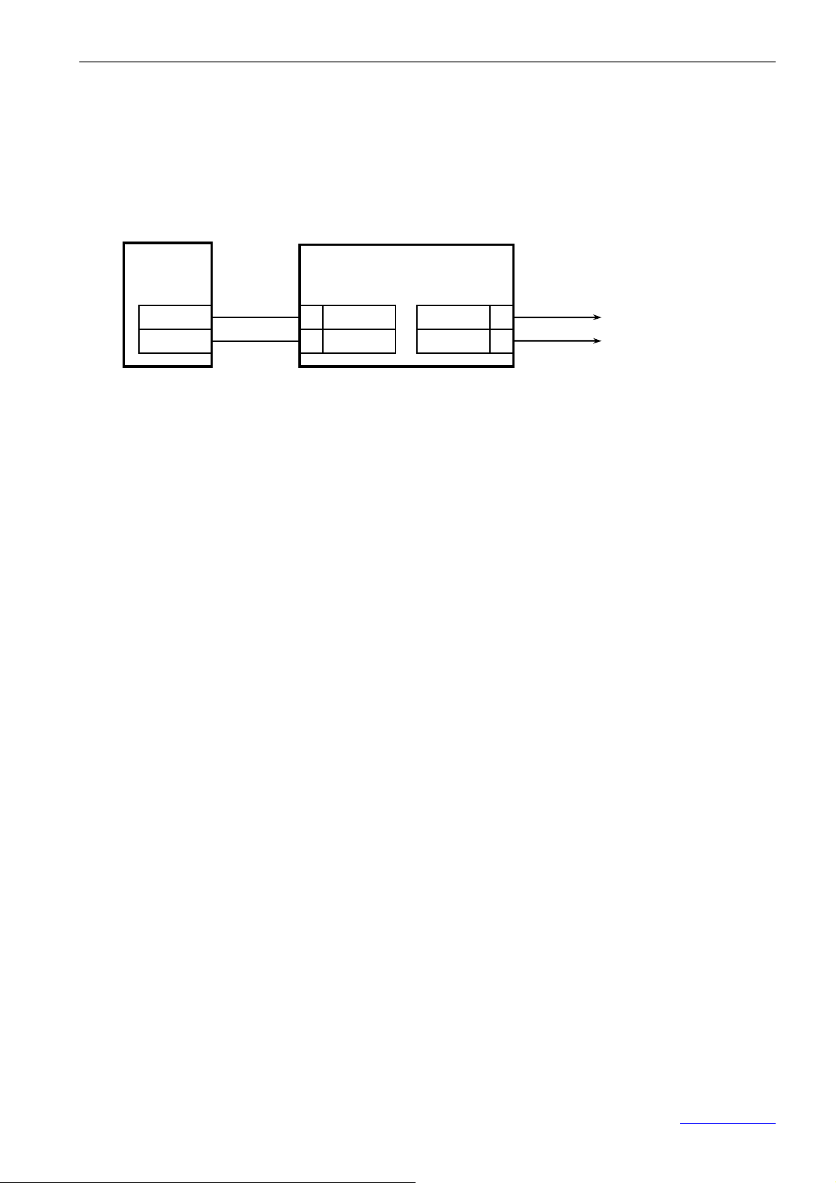
Mount and wire the S2000-К as shown in Figure 2. Wires are connected to the S2000-K by means of
the screw terminal blocks.
Power Supply
To a Network Controller
(Orion PC or S2000(М))
Figure 2. S2000-K Wiring Diagram
Connecting the Orion RS-485 Interface Bus
To connect the S2000-K to the network controller via the RS-485 interface bus connect A and B ter-
minals of the ХТ1.2 terminal block to the A and B wires of the RS-485 bus correspondently. If the
S2000-K is the first or the last device within the RS-485 bus, add the supplied termination resistor
620 W across the А and В terminals of the ХТ1.2.
WARNING! If the RS-485 interface bus is quite long (more than 1000 meters), use twisted-pair ca-
bling to connect the devices. The resistance value of each RS-485 interface line (A or B) measured
between the network controller and the most distant device MUST NOT exceed 200 W.
Connecting the Power Supply
Connect a direct power supply 10÷28 V @ 100 mА to the ХТ1.1 terminals of the S2000-К as shown in
Figure 2 coupling the 0 V circuit of the S2000-К with the 0 V circuit of the network controller. If both
the devices are powered by the same power supply, coupling can be omitted.
25 www.bolid.com
Page 26

Orion ISS
GETTING STARTED
After mounting and wiring the S2000-K, turn its power on. The keypad LCD shall backlight, the key-
pad sounder shall respond with a beep. The S2000-K being communicated with the network controller
over the RS-485 interface, the keypad LCD shall display the current time. Otherwise, the keypad LCD
shall display NO RS485 LINE, the keypad LED flashing once per a second.
In order the S2000-K to operate as a part of an Orion system it must be assigned to a unique network
address (see Section Programming the Network Address of the S2000-К of this Manual).
www.bolid.com 26
Page 27

S2000-К Programming
PROGRAMMING
27 www.bolid.com
Page 28
Orion ISS
After installing the S2000-K, set keypad configuration parameters and modify the network controller
database in order to use the S2000-K as a part of the Orion system.
To program the S2000-K connect it to a personal computer via one of the Bolid manufactured inter-
face converters such as S2000-PI, PI-GR, S2000(M) in the Converter Mode, S2000-USB, USB-
RS485, etc.. Install the Orion Device Configuration Tool, the UProg, on the computer. A fresh version
of the UProg can be downloaded from the site of the Bolid Company at the address of
www.bolid.com
The network address of the S2000-K can also be programmed with the help of the tools of the net-
work controller being in use.
To program the network controller use either the PProg Console Programming Tool (if an
S2000/S2000M/S2000L controls the system) or Database Administrator Software tools (if the system
operates under the Orion Software).
.
PROGRAMMING THE KEYPAD
The S2000-K keypad can be programmed by means of the UProg Configuration Tool.
To install the UProg, download its archive to the PC and unpack it to the relevant directory (for exam-
ple, the C:/Program Files/UProg). Run the UProg.exe file or create its shortcut on the desktop.
1. Find the devices connected to the computer by using the Device ® Read Device Configuration
command, or pressing <Ctrl+F3>, or selecting
of the COM port the keypad is connected to in the Search Devices window.
on the Toolbar. Select the proper number
2. Upon finding all the connected devices UProg outputs the list of the devices along with their net-
work addresses and version numbers on the display. Select the relevant S2000-K keypad and
press the Select command.
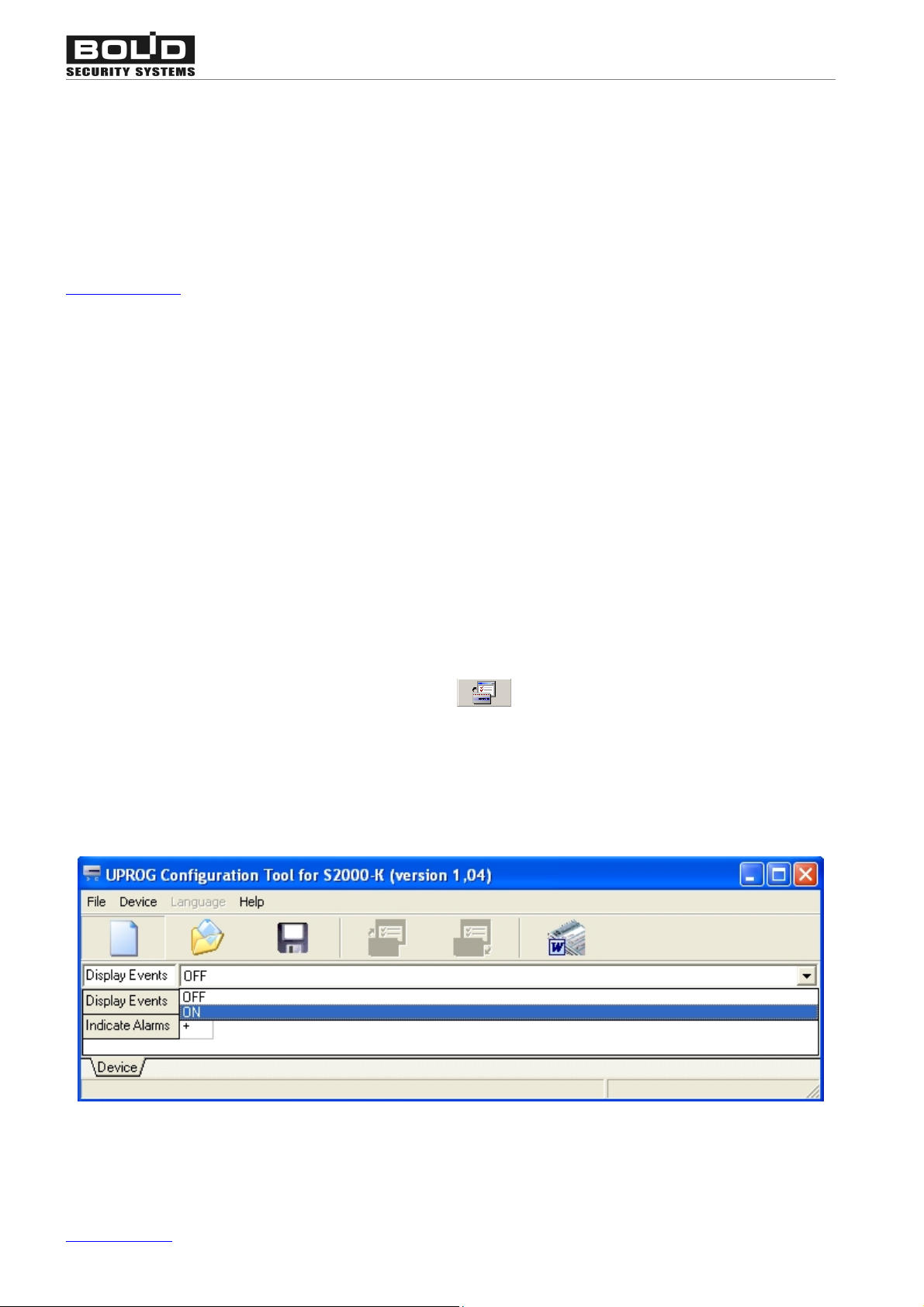
Figure 3
3. The UProg will display the current settings of the S2000-K which can be revised (see Figure 3).
www.bolid.com 28
Page 29
S2000-К Programming
To reach the S2000-K settings you can also read the keypad configuration from a data storage device
using the File ® Load Configuration File command (or the <F3> button on the PC keyboard, or the
tool).
Moreover, you can create a new configuration file for the S2000-К by means of the
File ® New Configuration command (or <Ctrl+N> buttons on the PC keyboard, or the
from the Toolbar).
The amended or newly created configuration can be:
Loaded into the keypad memory
Loaded into the memory of another
S2000-K connected to the PC, while
specifying the new network address
Written into a file
having an internal UProg format with
the .cnu extension
Written as a text into an MS Word
file
Device ® Write Configuration to Another Device
, Device ® Write Configuration to This Device
, <F2>, File ® Save Configuration to File
, «File» ® «Экспорт конфигурации в Microsoft Word»
tool
The S2000-К stores its settings in its non-volatile memory.
To identify the S2000-K keypad within a group of devices of an Orion system, the keypad must be
assigned to a unique number within the RS-485 interface line ¾ the network address ranged from 1
to 127 (see below). The factory setting for the network address of each Orion system device is 127.
If the keypad is supposed to be used for displaying system events and indicating system alarms re-
motely, this one must be programmed so as it can receive data from the network controller (see be-
low).
Programming the Network Address of the S2000-К
The network address of the S2000-К can also be programmed by means of S2000(M) console tools
as described in the Manual of the console being in use.
To define the network address of the S2000-К by means of the UProg Configuration Tool, select the
Device ® Change Device Address command and enter the proper address into the appeared dialog
box).
29 www.bolid.com
Page 30

Orion ISS
The specified address of the S2000-К can be unset to its factory value (127). To do this, remove the
keypad top cover and press the tamper switch by long-long-long-short pressing. Here the “long”
means “for more than 1 s” while the “short” means “for no more than half of a second”. The pauses
between pressings shall not exceed half a second each.
Programming the S2000-K to Display Events and Indicate Alarms
In order the S2000-K keypad can display system events received from the network controller, the
special keypad option, Display Events, must be enabled. If, moreover, the keypad is supposed to in-
dicate system alarms by flashing its LED and issuing various sound signals, the Indicate Alarms key-
pad option must be activated.
WARNING! In order to use the keypad for displaying messages and indicating alarms you MUST AL-
SO REVISE settings of the network controller (see page 31).
By default, displaying system event messages and indicating alarms are disabled for an S2000-K.
To activate these options, double click the left mouse button on the proper field or select the relevant
option and set the proper value from the dropdown list at the top right corner of the program window
(see Figure 3). Note, that alarms can be indicated only if events are being received from the network
controller, so always enable the Displaying Events option when you have activated the Indicate
Alarms option.
www.bolid.com 30
Page 31

S2000-К Programming
NETWORK CONTROLLER SETTINGS
The network controller can be programmed either by means of the PProg Console Configuration Tool
(if an S2000/S2000M/S2000/L is used as the network controller) or with the help of the Orion Data-
base Administrator Software (if the system operates under an Orion Software). Full description of the
network controller programming process can be found in the Manual for the network controller being
in use.
To program a network controller for operating an S2000-K keypad, the keypad descriptor along with
its network address is to be enrolled to the controller database (see below).
If the S2000-K keypad is to be used for entering user commands, do the following:
ØProgram in the controller database a list of users along with their authenticators (digital PIN
codes or codes of access devices such as iButtons or Proximity cards) which are enabled to
manage the system from the keypad, and
ØProgram the specific rights of these users to control specific partitions of the Orion system (Ac-
cess Groups), and
ØEnable managing the partitions by means the S2000-K keypad in question (see below)
If the S2000-K keypad is to be used for visualizing system events and indicating alarms, adjust the
mechanism of translating system events from the network controller to the S2000-K (see below).
Further in this Manual we describe some procedures of programming an S2000/S2000M/S2000L
console with the help of PProg Console Programming Tool. These and other common procedures are
described more closely in the Manual of the console being in use (or in the Database Administrator
Manual if the system operates under the Orion Software).
A fresh version of the PProg can be downloaded from the Bolid site at the address of www.bolid.com
How to enroll the S2000-К to the Console Database Using PProg
1. Run PProg.exe and find the devices connected to the computer by means of the
S2000 ® Read Configuration command. As a result, the program outputs the list of found de-
.
vices along with their addresses, types, and version numbers.
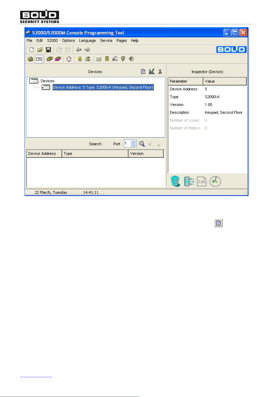
2. Add the S2000-K descriptor to the device tree by dragging them from the Search window and
dropping on the Devices window (see Figure 4). If necessary, assign the keypad to a textual de-
scription or revise its other parameters in the Inspector (Device) window.
31 www.bolid.com
Page 32
Orion ISS
Figure 4
Also, you can add the S2000-K descriptor to the console database by means of the tool from the
Devices window toolbar, defining all the keypad parameters manually.
Programming the Console for Receiving Commands from the Keypad
In order to use the S2000-К as a device for input user control commands, define in the console data-
base:
ØRights of specific users to control specific system partitions, and
ØRights of the keypad to be used as a device controlling these partitions
User rights are defined by means of including users to Access Groups programmed for the console
and assigned to these partitions as well as available operations for these partitions, namely arming
and disarming, arming only, disarming only, or status observing only. Users are authenticated in an
Orion system via programmed digital PIN codes or registered electronic access devices such as iBut-
tons or Proximity cards. Presenting a user authenticator to one of the system reader is treated as a
www.bolid.com 32
Page 33
S2000-К Programming
control command. The procedures of programming user rights are common and out of the scope of
this Manual.
If the S2000-K is used for authorized access requests, each user should be assigned to an access
code for passages through the specific doors. An access code can be used both for access control
and arming/disarming the S2000-K.
Keypad rights are defined by specifying in the controller database the list of partitions which can be
managed using the S2000-K. There are two ways for users to be authorized by the system to enter
partition control commands using the S2000-K. The first way is to enter a digital PIN code directly
from the S2000-K keypad. The second way is to present an electronic access device (iButton or Prox-
imity card) to a reader connected to another device in the same RS-485 bus (such as S2000-4,
S2000-2, S2000-KDL, etc.) and then operate the S2000-K to control available partitions. The last
combined mechanism provides both enhanced security due to using electronic access devices and
flexible and versatile control enabling users to select partitions and actions individually via a menu
and to track system responses on the keypad LCD.
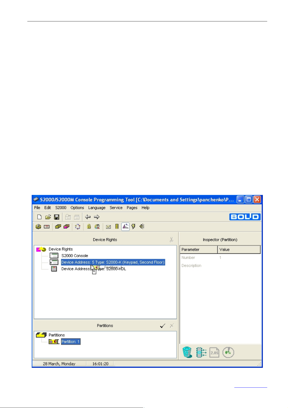
For the PProg, the keypad rights are programmed using the Device Rights tab (see Figure 5). The
upper window will contain the list of devices enrolled in the console database, the bottom window dis-
playing the list of system partitions.
Figure 5
33 www.bolid.com
Page 34
Orion ISS
To assign the S2000-K keypad to the list of partitions provided that users will be authorized via enter-
ing their PIN codes directly from the keypad, drag and drop the relevant partition descriptors from the
bottom window on the keypad descriptor in the Device Rights window as shown in Figure 5.
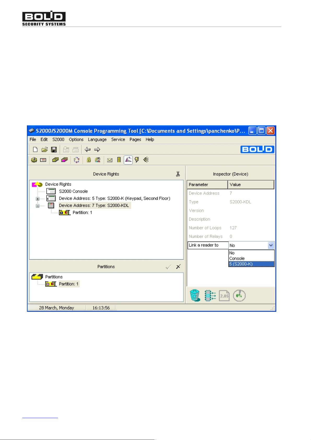
To control partitions by the combined way of authorization/control, firstly assign the controlled partition
(partitions) to a device whose reader will be used for user authentication. (In our example it will be the
S2000-KDL – see Figure 7.) Then select the device in the Device Rights window and define its "Link a
Reader to" parameter in the Inspector window specifying the S2000-K in question as the device which
is supposed to control partitions after user authentication by means of presenting access device to the
reader of the specified S2000-KDL.
Figure 6
Programming the Mechanism of Translating Events
To program the network controller to translate events to the specified S2000-K do the following:
ØDefine in the controller database the list of partitions which events will be translated to the
S2000-K, then
ØSpecify the S2000-K as the device which the events will be translated to, and
ØDefine the types of events that are enabled to be translated to the S2000-K for displaying
www.bolid.com 34
Page 35
S2000-К Programming
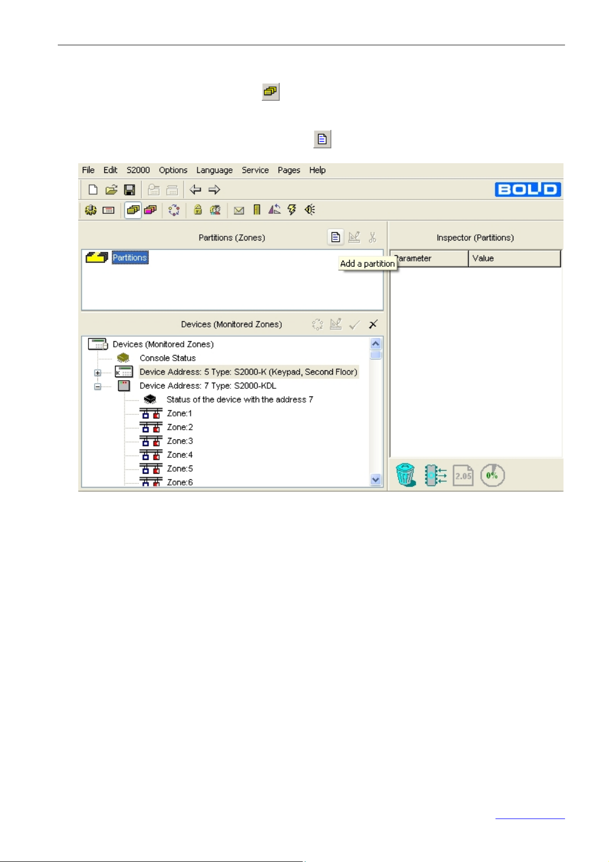
For the PProg, use the following procedure.
1. Select the Partitions tab by pressing
buttons on the Quick Access Toolbar, or activating the Pages®Partitions®Partitions menu com-
mand. Add a new partition descriptor by clicking
on the Page Icon Toolbar, or browsing pages by arrow
(see Figure 7).
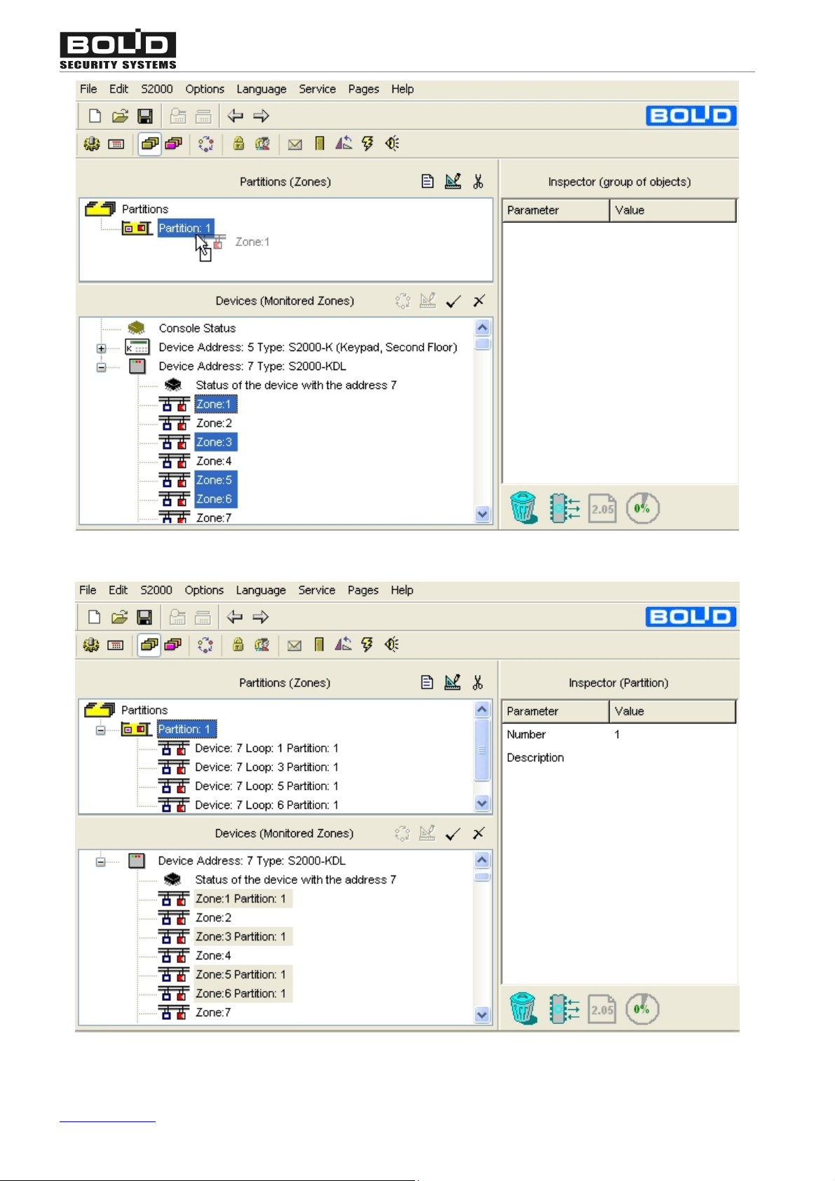
Figure 7
Then, in the bottom window select a group of the zones which will be included to the new partition
and drag and drop them on the partition descriptor (see Figure 8 and Figure 9).
35 www.bolid.com
Page 36
Orion ISS
Figure 8
Figure 9
www.bolid.com 36
Page 37
S2000-К Programming
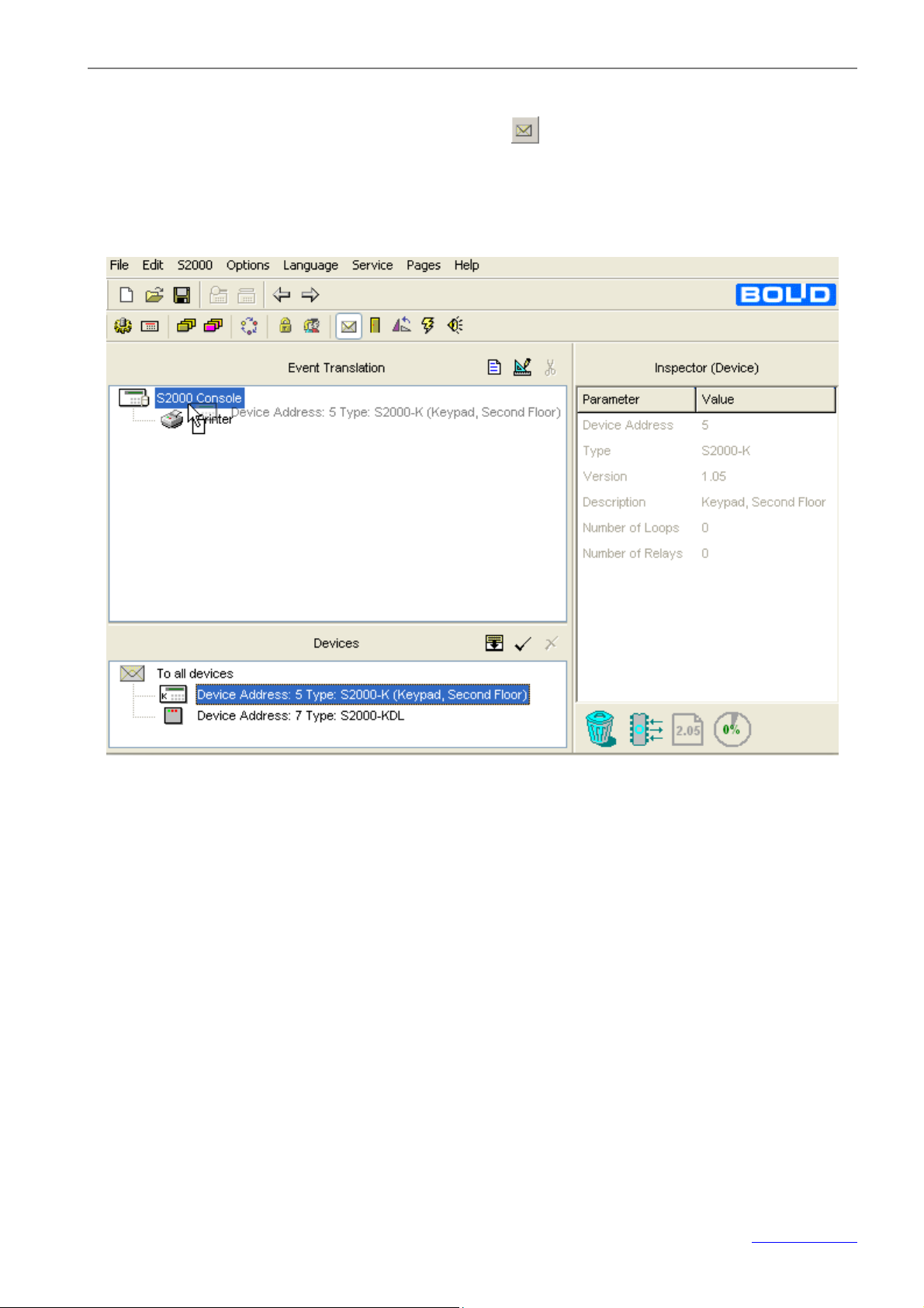
2. Specify the keypad as the device the events in the selected partitions will be translated to. For do-
ing so, go to the Event Translation tab by pressing
Access Toolbar, or selecting the Pages®Others®Event Translation menu command. Drag the
keypad descriptor in the Devices window and drop them on the device tree in the Event Translation
window (see Figure 10).
, or browsing arrow buttons on the Quick
Figure 10
37 www.bolid.com
Page 38
Orion ISS
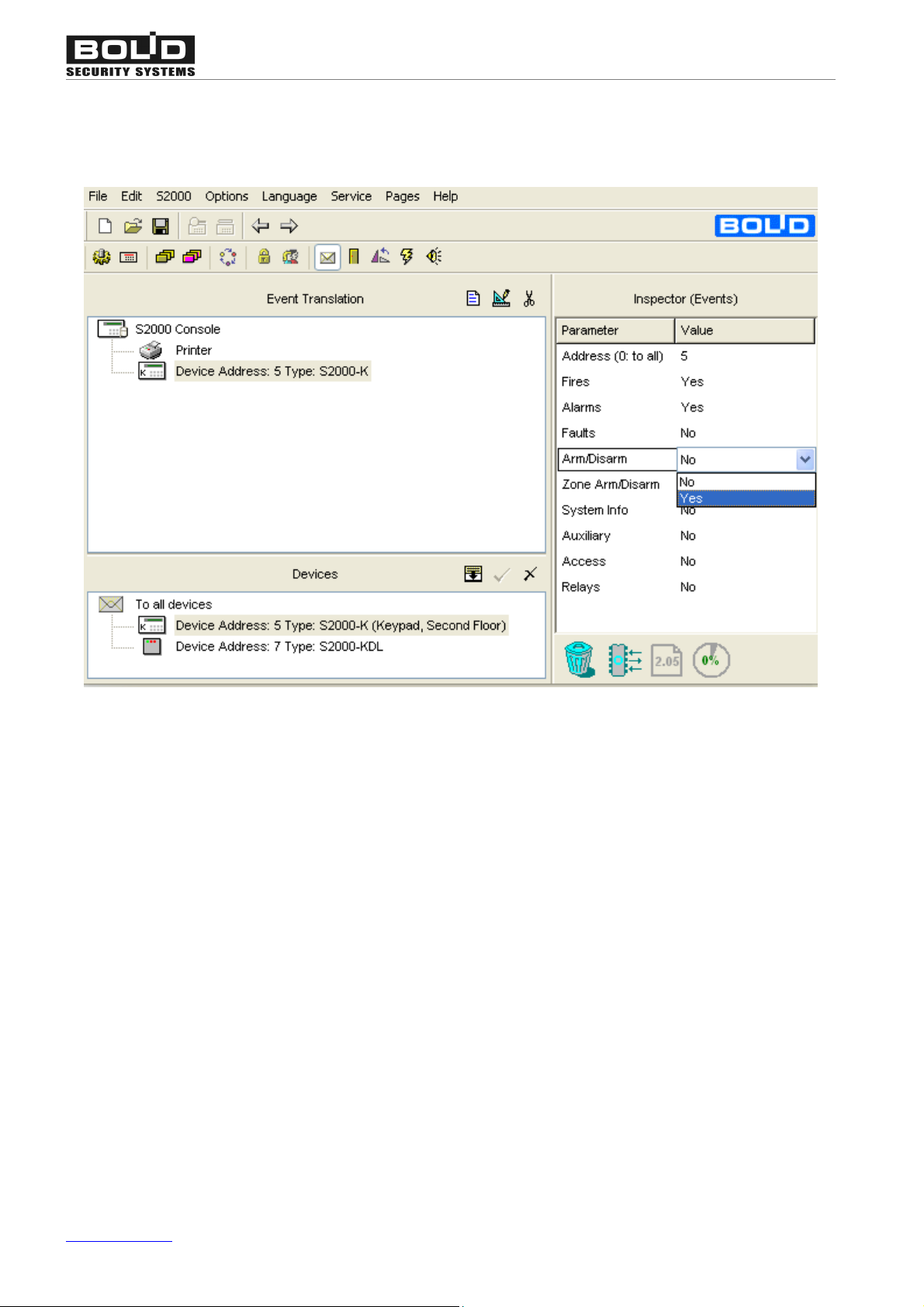
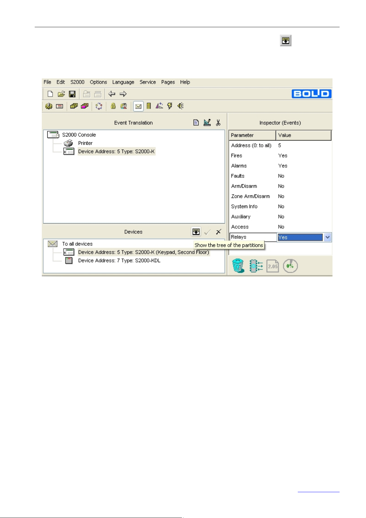
3. The keypad descriptor being selected in the Event Translation window, define in the Inspector
window the kinds of events which are supposed to be displayed by the keypad (see Figure
11).
Figure 11
www.bolid.com 38
Page 39
S2000-К Programming
4. Switch the bottom window of the page to the partition display mode by clicking (see Figure 12)
or selecting the relevant menu command. The list of system partitions will appear in the bottom
window.
Figure 12
39 www.bolid.com
Page 40
Orion ISS
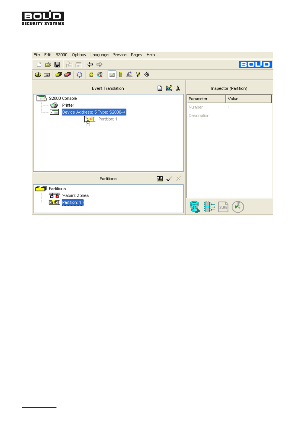
5. Drag and drop the partitions which events will be displayed by the keypad from the Partitions win-
dow on the keypad descriptor in the Event Translation window (see Figure 13).
6. Now configuring is completed.
Figure 13
www.bolid.com 40
Page 41

S2000-К Maintenance
MAINTENANCE
41 www.bolid.com
Page 42

TROUBLESHOOTING
properly
Reverse
Orion ISS
s After the S2000-K is turned on, its
display shows nothing
s S2000-K
displays ‘NO RS485 LINE’,
with LED flashing once per second
s No messages are displayed by the
keypad LCD
and/or
s Keypad sounder is silent when the
keypad receives alarm messages,
although pressing keypad keys
cause the S2000-K to sound
Make sure that power is applied to the power terminals of
the S2000-К
Check whether the keypad is properly connected to the
network controller via the RS-485 interface
Make sure the А and В wires of the RS-485 bus are
connected to the А and В keypad terminal block.
their positions if necessary
The options of keypad’s displaying system events and indicating alarms are disabled by default. To program these
options, examine the settings of the S2000-K and the network controller being in use. For more about this, see Section Programming of this Manual.
1. Connecting the S2000-K to a computer with the run
UProg Configuration Tool, make sure the Display
Events option and Indicate Alarms Options are activated for the keypad. Note, that indicating alarms can
be enabled only if displaying events is enabled.
2. Running the PProg Programming Tool or Orion Software tools, make sure that:
s The time displayed by the S2000-K
differs from that displayed by the
S2000/S2000M console
- the S2000-K is enrolled in the list of devices con-
nected to the network controller, and
- the S2000-К is specified as the device the controller
translates events to, and
- the network controller is programmed to translate the
specified kinds of events occurred in the specified partitions to the S2000-K..
Such a situation can happen in case of the console power’s being off for some time.
To fix the problem, set the correct time of the
S2000/S2000M manually. After that, the console will automatically synchronize all the devices connected via the
RS-485 interface.
www.bolid.com 42
Page 43
S2000-К Maintenance
+
V
0
V
S
2000-К
BA4
3
+
Vp
0
V21
XT1.1
XT1.2
S
2000(М
)
BA4
3
+
Vp
0
V21
XT1.1
XT1.2
A
V
R2
INSPECTION
Once per a year personnel of the Service Company shall perform a scheduled inspection of the
S2000-K in order to check its operation condition and find out potential defects. If during the warranty
period the keypad does not meet any requirements set forth in this section, this will be the grounds to
raise a climb to the manufacturer.
An inspection shall be carried out under the normal ambient conditions, namely:
- The temperature of 25 °С
- The relative humidity of 45 % to 80 %
- The atmospheric pressure of 630 to 800 mm
To inspect the S2000-K keypad, do the following:
Ø Examine the keypad for fouling or mechanical damage, than
Ø Examine the keypad terminal blocks and tighten loosen screws if necessary, and
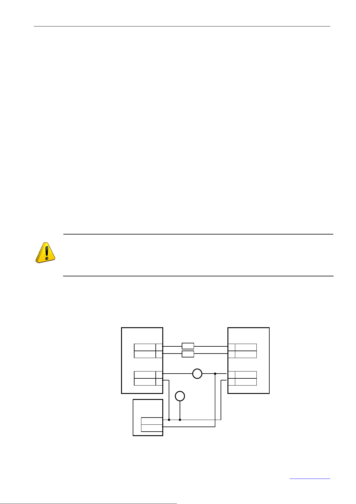
Ø Test S2000-К operability having wired the keypad as shown in Figure 14. The testing procedure
has been described below in this Section.
WARNING!
While inspecting the keypad, disconnect the S2000-K power supply before connecting
and disconnecting wires
R1
Power Supply
10-30V , 200мА
Figure 14. Wiring the S2000-K While Testing the Keypad Operability
41 www.bolid.com
Page 44

Orion ISS
S2000-K Testing Procedure
For testing operability of the S2000-K, wire the keypad as shown in Figure 14. Two resistors of 220 Ω
and 0.125 W, R1 and R2, shall be brought between the S2000/S2000M console and the S2000-K
keypad as shown in the diagram in order to introduce damping into the communication line between
the devices.
The keypad pre-operation time doesn’t exceed three seconds.
1. Establish the test set-up as shown in Figure 14, not connecting wires of the RS-485 bus to
terminal blocks of the S2000(M) console. Set the keypad power supply voltage equal to (10.2
± 0.3) V.
2. Turn the S2000-K power supply on. The keypad sounder shall make a beep. The keypad LCD
and keys shall backlight. The keypad LED shall flash once per a second, the keypad LCD displaying NO RS485 LINE.
3. Press any key on the keypad. A beep shall follow pressing the key.
4. Connect wires of the RS-485 interface bus to the terminal blocks of the S2000/S2000M console. The console shall indicate having found the device with the current address of the
S2000-K followed by resetting this device within a minute.
5. Press the keypad tamper switch and keep it pressed for at least 15 s; then release this one.
The S2000(M) console shall receive a tamper alarm from the keypad. Then press the keypad
tamper switch once more and hold it until the console receives a tamper restored notification
from the keypad.
6. Measure the current consumed by the S2000-K. The value shall not exceed 80 мА.
7. Set the keypad input voltage to 28 V. Repeat the test from the Step 2. The measured current
consumed by the S2000-K shall not exceed 30 мА.
8. Write the results of the inspection of the S2000-K into a keypad maintenance log book.
www.bolid.com 42
Page 45

S2000-К
Appendix
System Events Displayed by the Keypad LCD
9 www.bolid.com
Page 46
Orion ISS
partition #7 has just been armed in response to
partition #7 has just been disarmed in response
The alarm loop #3 connected to the device #18 and
The alarm loop #3 connected to the device #18 and
address 7; the number of
has been detected within the
alarm loop #3 which belongs to the device #1 and is
has been detected within the
larm loop #3 which belongs to the device #1 and is
The alarm loop #3 connected to the device #18 and
status which means that fire can happen within the
Partition Armed
Partition Disarmed
Loop Armed
Loop Disarmed
Arming Failed
Zone
Disconnected
Loop Open Failure
Loop Short Failure
ARM 7 U 80
DARM 7 U 11
ARM 7 018/003
DARM 7 018/003
FARM 7 018/003
ZTD 2 007/001
LTO 14 001/003
LTS 14 001/003
The
presenting user authenticator #80
The
to presenting user authenticator #11
included into the partition #7 has just been armed
included into the partition #7 has just been disarmed
Arming the loop #3 connected to the device #18 and
included to the partition #7 has failed
An addressable device which belongs to the partition
#2 has been disconnected from the polling loop of the
S2000-KDL with the network
the device in the polling loop is 1
An open circuit failure
included into the partition #14
A short circuit failure
a
included into the partition #14
Fire Signal
Intrusion
Alarm
Silent Alarm
Fire Pre-Alarm
Fire Alarm
Loop Tamper
Alarm
Loop Tamper
Restored
FS 14 001/003
IA 7 018/003
SA 1 018/002
FPA 14 001/003
FA 14 001/003
TA 7 001/004
TR 7 001/004
A fire detector response has been received via the
alarm loop #3 connected to the device #1 and included into the partition #14
included into the partition #7 has just been broken
The alarm loop #2 connected to the device #18 and
included into the partition #1 has just been broken
The alarm loop #3 of the device #1 included into the
partition #14 has responded with the Fire Prealarm
protected area
The alarm loop #3 of the device #1 included into the
partition #14 has responded with the Fire Alarm status
Opening (tampering) the enclosure of the detector included into the intrusion alarm loop #4 of the device
#1 included into the partition #7
Closing the enclosure of the detector included into the
intrusion alarm loop #4 of the device #1 included into
the partition #7
www.bolid.com 42
Page 47
S2000-К
to a reader of the device with
with
address
:
o a
fied
has just been closed after being held open
User’s Code
Entered
Local User’s
Code Entered
Device Tamper
Alarm
Device Tamper
Restored
Device
Connected
Device
Disconnected
Device Restarted
Power Failure
ECOD 80 D007
ECOD 405(l) D001
TA D001
TR D001
CONNECT D018
DISCONNECT D018
RESTART D018
PWRF D018
A user has presented
the network address 7 the authenticator #80 registered by the network controller
A user has presented to a reader of the device
the network address #1 the authenticator #405 registered by the device itself
The enclosure of the device with the network
1 has been open
The enclosure of the device with the network address
1 has been closed
The network controller has found the device with the
address 18 within the connected RS-485 interface bus
Communication between the network controller and
the device with the network number 18 has been lost
or the device has been replaced
The device with the network address 18 has been restarted
The input voltage of the device with the network address 18 is out of the normal range
Access
Granted
Access Denied
Illegal Code
Door Forced Open
Door Held Open
Door Closed
Local
Programming
AG 41 D001
AD 41 D001
ICOD D001
DRF D001
DRO D001
DRC D001
PROGR D001
The device with the network address 41 has made a
decision to grant access via its protected door t
user having presented the authenticator #41
The authenticator #41 has been read by a reader of
the device with the network address 1, the authenticator being not authorized to gain access to the operation requested
An unknown authenticator has been presented to a
reader of the device with the network address 1
The door monitored by the device with the network
address 1 has just been open without granting access
The door monitored by the device with the network
address 1 has been open for more than a speci
time
The door monitored by the device with the network
address 1
or forced open
The device with the network address 1 has entered
the Key Programming Mode
41 www.bolid.com
Page 48

Page 49

BOLID ONE YEAR LIMITED WARRANTY
Bolid Company and its divisions and subsidiaries («Seller»), 4 Pionerskaya Str., Korolev 141070, Moscow Region, Russia warrants its security equipment (the «product») to be free from defects in materials and workmanship for one year from date of original purchase, under normal use and service. Seller’s obligation is limited to
repairing or replacing, at its option, free of charge for parts or labor, any product proven to be defective in materials or workmanship under normal use and service. Seller is not responsible for results where the product is
used improperly, where it is used for any application it is not intended for, used under unacceptable environmental conditions and mishandled or stored under improperly. Seller shall have no obligation under this warranty or otherwise if the product is altered or improperly repaired or serviced by anyone other than the Seller. In
case of defect, contact the security professional who installed and maintains your security equipment or the
Seller for product repair.
This one year Limited Warranty is in lieu of all other express warranties, obligations or liabilities. THERE ARE
NO EXPRESS WARRANTIES, W HICH EXTEND BEYOND THE FACE HEREOF. ANY IMPLIED WARRANTIES, OBLIGATIONS OR LIABILITIES MADE BY SELLER IN CONNECTION WITH THIS PRODUCT, INCLUDING ANY IMPLIED WARRANTY OF MERCHANTABILITY, OR FITNESS FOR A PARTICULAR PURPOSE OR
OTHERWISE, ARE LIMITED IN DURATION TO A PERIOD OF ONE YEAR FROM THE DATE OF ORIGINAL
PURCHASE. ANY ACTION FOR BREACH OF ANY WARRANTY, INCLUDING BUT NOT LIMITED TO ANY
IMPLIED WARRANTY OF MERCHANTABILITY, MUST BE BROUGHT WITHIN 12 MONTHS FROM DATE OF
ORIGINAL PURCHASE. IN NO CASE SHALL SELLER BE LIABLE TO ANYONE FOR ANY CONSEQUENTIAL
OR INCIDENTAL DAMAGES FOR BREACH OF THIS OR ANY OTHER WARRANTY, EXPRESS OR IMPLIED,
OR UPON ANY OTHER BASIS OF LIABILITY WHATSOEVER, EVEN IF THE LOSS OR DAMAGE IS
CAUSED BY THE SELLER’S OWN NEGLIGENCE OR FAULT. Some countries do not allow limitation on how
long an implied warranty lasts or the exclusion or limitation of incidental or consequential damages, so the
above limitation or exclusion may not apply to you.
Seller does not represent that the product may not be compromised or circumvented; that the product will prevent any personal injury or property loss by burglary, robbery, fire or otherwise; or that the product will in all
cases provide adequate warning or protection. Buyer understands that a properly installed and maintained
alarm may only reduce the risk of a burglary, robbery, fire or other events occurring without providing an alarm,
but it is not insurance or guarantee that such will not occur or that there will be no personal injury or property
loss as a result. CONSEQUENTLY, SELLER SHALL HAVE NO LIABILITY FOR ANY PERSONAL INJURY,
PROPERTY DAMAGE OR OTHER LOSS BASED ON A CLAIM THE PRODUCT FAILED TO GIVE WARNING.
HOWEVER, IF SELLER IS HELD LIABLE, WHETHER DIRECTLY OR INDIRECTLY, FOR ANY LOSS OR
DAMAGE ARISING UNDER THIS LIMITED WARRANTY OR OTHERWISE, REGARDLESS OF CAUSE OR
ORIGIN, SELLER’S MAXIMUM LIABILITY SHALL NOT IN ANY CASE EXCEED THE PURCHASE PRICE OF
THE PRODUCT, WHICH SHALL BE THE COMPLETE AND EXCLUSIVE REMEDY AGAINST SELLER. This
warranty gives you specific legal rights, and you may also have other rights which vary from country to country.
No increase or alteration, written or verbal, to this warranty is authorized.
Page 50

4 Pionerskaya Str., Korolev 141070,
Moscow Region, Russia
Phone/fax: +7 495 775-71-55
Email: [email protected]
www.bolid.com
 Loading...