

Page 1
Operator s Manual
TRANSMATIC
GARDEN
TRACTORS
Models
820 thru 829
840 thru 849
IMPORTANT: READ SAFETY RULES AND INSTRUCTIONS CAREFULLY
Warning: This unit is equipped with an internal combustion engine and should not be used on or near any unimproved forest-
covered, brush-covered or grass-covered land unless the engine’s exhaust system is equipped with a spark arrester meeting
applicable local or state laws (if any). If a spark arrester is used, it should be maintained in effective working order by the operator.
In the State of California the above is required by law (Section 4442 of the California Public Resources Code). Other states may have
similar laws. Federal laws apply on federal lands. A spark arrester for the muffler is available through your nearest engine authorized
service dealer or contact the service department, P.O. Box 368022 Cleveland, Ohio 44136-9722.
MTD PRODUCTS INC. P.O. BOX 368022 CLEVELAND, OHIO 44136-9722
PRINTED IN U.S.A.
FORM NO. 770-10119
(10/98)
Page 2

SECTION 1: FINDING YOUR MODEL NUMBER
This Operator’s Manual is an important part of your new lawn tractor. It will help you assemble, prepare and
maintain your lawn tractor. Please read and understand what it says.
Before you start to prepare your lawn tractor for its first use, please locate the model plate and copy the
information from it in this Operator's Manual. The information on the model plate is very important if you need
help from your dealer or the MTD customer support department.
• Every lawn tractor has a model plate. You can locate it by pivoting the seat forward and looking under
the seat at the seat pivot bracket. See Figure 1.
This is where your model number will be.
xxx-x-xxx-x-xxx xxxxxxxxxxx
-This is where your serial number will be.
Copy the model number here:.
MTD PRODUCTS INC
CLEVELAND, OHIO 44136
Copy the serial number here: _
Figure 1
SECTION 2: CALLING CUSTOMER SUPPORT
• LOCATE YOUR MODEL NUMBER AND SERIAL NUMBER — Record this information in the space
provided. To find your unit’s specific model number and serial number, see SECTION 1: FINDING
YOUR MODEL NUMBER.
• If you are having difficulty assembling this product or if you have any questions regarding the controls,
operation or maintenance of this unit, please call the Customer Support Department.
• Customer Support can be reached by dialing: 1- (330) 220-4MTD
(4683)
or
1- (800)-800-7310
Please have your model number and serial number ready when you call.
Although both numbers are important, you will be asked to enter only your serial number before your
call can be processed.
Page 3

SECTION 3: IMPORTANT SAFE OPERATION PRACTICES
WARNING: THIS SYMBOL POINTS OUT IMPORTANT SAFETY INSTRUCTIONS WHICH, IF NOT
A
FOLLOWED, COULD ENDANGER THE PERSONAL SAFETY AND/OR PROPERTY OF YOURSELF
AND OTHERS. READ AND FOLLOW ALL INSTRUCTIONS IN THIS MANUAL BEFORE ATTEMPTING
TO OPERATE YOUR LAWN MOWER. FAILURE TO COMPLY WITH THESE INSTRUCTIONS MAY
RESULT IN PERSONAL INJURY. WHEN YOU SEE THIS SYMBOL, HEED ITS WARNING.
WARNING: The Engine Exhaust from this product contains chemicals known to the
A
A
1. GENERAL OPERATION
State of California to cause cancer, birth defects or other reproductive harm.
DANGER: Your lawn mower was built to be operated according to the rules for safe operation in this
manual. As with any type of power equipment, carelessness or error on the part of the operator can
result in serious injury. This lawn mower is capable of amputating hands and feet and throwing objects.
Failure to observe the following safety instructions could result in serious injury or death.
• Read, understand, and follow all instructions in the
operator’s manual and on the machine before
starting. Keep this manual in a safe place for future
and regular reference and for ordering replacement
parts.
• Only allow responsible individuals familiar with the
instructions to operate the machine. Know controls
and how to stop the machine quickly.
• Do not put hands or feet under cutting deck or near
rotating parts.
• Clear the area of objects such as rocks, toys, wire,
etc., which could be picked up and thrown by the
blade. A small object may have been overlooked and
could be accidentally thrown by the mower in any
direction and cause injury to you or a bystander. To
help avoid a thrown objects injury, keep children,
bystanders and helpers at least 75 feet from the
mower while it is in operation. Always wear safety
glasses or safety goggles during operation or while
performing an adjustment or repair, to protect eyes
from foreign objects. Stop the blade(s) when crossing
gravel drives, walks or roads.
• Be sure the area is clear of other people before
mowing. Stop machine if anyone enters the area.
• Never carry passengers.
• Disengage blade(s) before shifting into reverse and
backing up. Always look down and behind before and
while backing.
• Be aware of the mower and attachment discharge
direction and do not point it at anyone. Do not operate
the mower without either the entire grass catcher or
the chute guard in place.
• Slow down before turning. Operate the machine
smoothly. Avoid erratic operation and excessive
speed.
Never leave a running machine unattended. Always
turn off blade(s), place transmission in neutral, set
park brake, stop engine and remove key before
dismounting.
Turn off blade(s) when not mowing.
Stop engine and wait until blade(s) comes to a
complete stop before (a) removing grass catcher or
unclogging chute, or (b) making any repairs, adjusting
or removing any grass or debris.
Mow only in daylight or good artificial light.
Do not operate the machine while under the influence
of alcohol or drugs.
Watch for traffic when operating near or crossing
roadways.
Use extra care when loading or unloading the
machine into a trailer or truck. This unit should not be
driven up or down a ramp onto a trailer or truck under
power, because the unit could tip over, causing
serious personal injury. The unit must be pushed
manually on a ramp to load or unload properly.
Never make a cutting height adjustment while engine
is running if operator must dismount to do so.
Wear sturdy, rough-soled work shoes and close-fitting
slacks and shirts. Do not wear loose fitting clothes or
jewelry. They can be caught in moving parts. Never
operate a unit in bare feet, sandals, or sneakers.
Check overhead clearance carefully before driving
under power lines, wires, bridges or low hanging tree
branches, before entering or leaving buildings, or in
any other situation where the operator may be struck
or pulled from the unit, which could result in serious
injury.
Disengage all attachment clutches, thoroughly
depress the brake pedal, and shift into neutral before
attempting to start engine.
Page 4

• Your mower is designed to cut normal residential
grass of a height no more than 10". Do not attempt to
mow through unusually tall, dry grass (e.g., pasture)
or piles of dry leaves. Debris may build up on the
mower deck or contact the engine exhaust presenting
a potential fire hazard.
2. SLOPE OPERATION
Slopes are a major factor related to loss of control and tipover accidents which can result in severe injury or death. All
slopes require extra caution. If you cannot back up the slope
or if you feel uneasy on it, do not mow it.
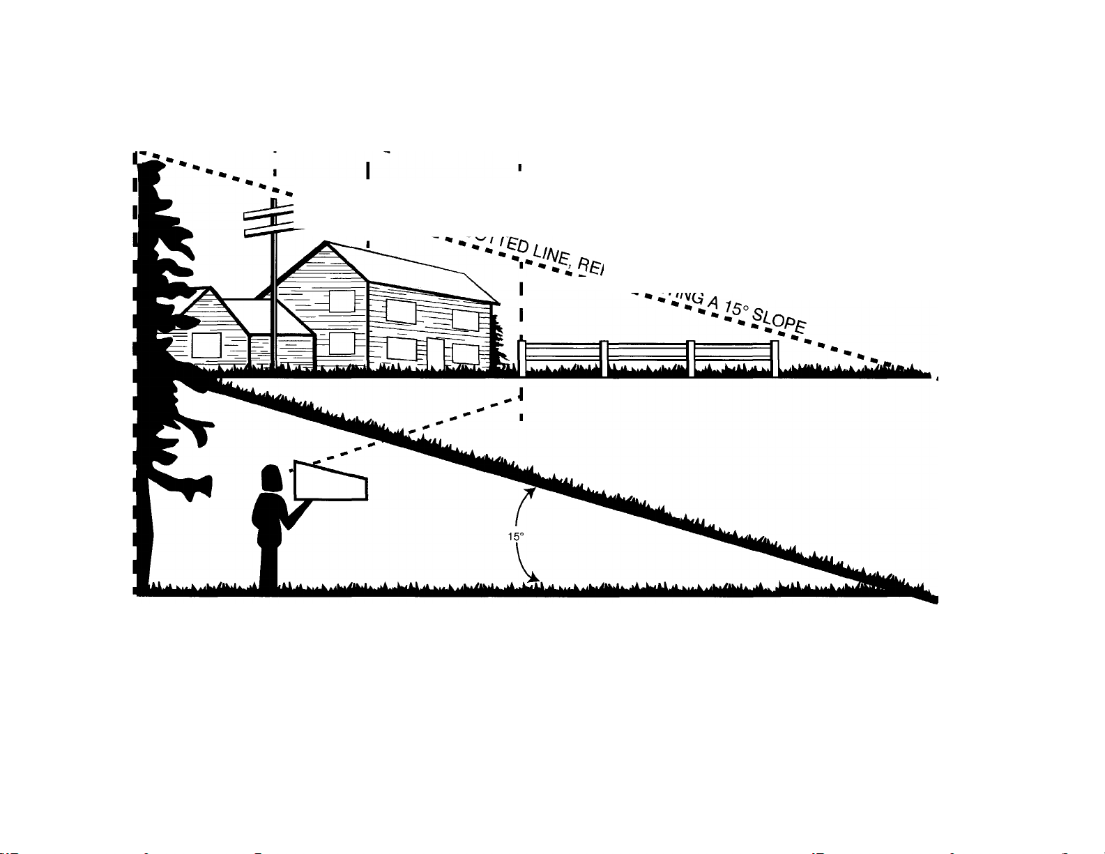
For your safety, use the slope gauge included as part of this
manual to measure slopes before operating this unit on a
sloped or hilly area. If the slope is greater than 15° as shown
on the slope gauge, do not operate this unit on that area or
serious injury could result.
DO:
Mow up and down slopes, not across.
Remove obstacles such as rocks, limbs, etc.
Watch for holes, ruts or bumps. Uneven terrain could
overturn the machine. Tall grass can hide obstacles.
Use slow speed. Choose a low enough gear so that
you will not have to stop or shift while on the slope.
Always keep machine in gear when going down
slopes to take advantage of engine braking action.
Follow the manufacturer’s recommendations for
wheel weights or counterweights to improve stability.
Use extra care with grass catchers or other
attachments. These can change the stability of the
machine.
Keep all movement on the slopes slow and gradual.
Do not make sudden changes in speed or direction.
Rapid engagement or braking could cause the front of
the machine to lift and rapidly flip over backwards
which could cause serious injury.
Avoid starting or stopping on a slope. If tires lose
traction, disengage the blade(s) and proceed slowly
straight down the slope.
DO NOT:
Do not turn on slopes unless necessary; then, turn
slowly and gradually downhill, if possible.
Do not mow near drop-offs, ditches or embankments.
The mower could suddenly turn over if a wheel is
over the edge of a cliff or ditch, or if an edge caves in.
Do not mow on wet grass. Reduced traction could
cause sliding.
Do not try to stabilize the machine by putting your foot
on the ground.
Do not use grass catcher on steep slopes.
3. CHILDREN
Tragic accidents can occur if the operator is not alert to the
presence of children. Children are often attracted to the
machine and the mowing activity. Never assume that children
will remain where you last saw them.
Keep children out of the mowing area and in watchful
care of an adult other than the operator.
Be alert and turn machine off if children enter the
area.
Before and when backing, look behind and down for
small children.
Never carry children, even with the blades off. They
may fall off and be seriously injured or interfere with
the safe machine operation.
Never allow children under 14 years old to operate
the machine. Children 14 years and over should only
operate machine under close parental supervision
and proper instruction.
Use extra care when approaching blind corners,
shrubs, trees or other objects that may obscure your
vision of a child or other hazard.
Remove key when machine is unattended to prevent
unauthorized operation.
4. SERVICE
Use extreme care in handling gasoline and other
fuels. They are extremely flammable and the vapors
are explosive.
Use only an approved container.
Never remove fuel cap or add fuel with the engine
running. Allow engine to cool at least two minutes
before refueling.
Replace fuel cap securely and wipe off any spilled
fuel before starting the engine as it may cause a fire
or explosion.
Extinguish all cigarettes, cigars, pipes and other
sources of ignition.
Never refuel the machine indoors because fuel
vapors will accumulate in the area.
Never store the fuel container or machine inside
where there is an open flame or spark, such as a gas
hot water heater, space heater or furnace.
Never run a machine inside a closed area.
To reduce fire hazard, keep the machine free of
grass, leaves or other debris build-up. Clean up oil or
fuel spillage. Allow machine to cool at least 5 minutes
before storing.
Before cleaning, repairing or inspecting, make certain
the blade and all moving parts have stopped.
Disconnect the spark plug wire, and keep the wire
away from the spark plug to prevent accidental
starting.
Page 5
Check the blade and engine mounting bolts at
frequent intervals for proper tightness. Also,
visually inspect blade for damage (e.g., excessive
wear, bent, cracked). Replace with blade which
meets original equipment specifications.
Keep all nuts, bolts and screws tight to be sure the
equipment is in safe working condition.
Never tamper with safety devices. Check their
proper operation regularly. Use all guards as
instructed in this manual.
After striking a foreign object, stop the engine,
remove the wire from the spark plug and thoroughly
inspect the mower for any damage. Repair the
damage before restarting and operating the mower.
Grass catcher components are subject to wear,
damage and deterioration, which could expose
moving parts or allow objects to be thrown. For
your safety protection, frequently check
components and replace with manufacturer’s
recommended parts when necessary.
Mower blades are sharp and can cut. Wrap the
blade(s) or wear gloves and use extra caution
when servicing blade(s).
Check brake operation frequently. Adjust and
service as required.
Muffler, engine and belt guards become hot during
operation and can cause a burn. Allow to cool
down before touching.
Do not change the engine governor settings or
overspeed the engine. Excessive engine speeds
are dangerous.
Observe proper disposal laws and regulations.
Improper disposal of fluids and materials can harm
the environment and the ecology.
Prior to disposal, determine the proper method to
dispose of waste from your local Environmental
Protection Agency. Recycling centers are
established to properly dispose of materials in an
environmentally safe fashion.
Use proper containers when draining fluids. Do not
use food or beverage containers that may mislead
someone into drinking from them. Properly dispose
of the containers immediately following the draining
of fluids.
DO NOT pour oil or other fluids into the ground,
down a drain or into a stream, pond, lake or other
body of water. Observe Environmental Protection
Agency regulations when disposing of oil, fuel,
coolant, brake fluid, filters, batteries, tires and other
harmful waste.
WARNING - YOUR RESPONSIBILITY: Restrict the use of this power machine to persons
A
who read, understand and follow the warnings and instructions in this manual and on the machine.
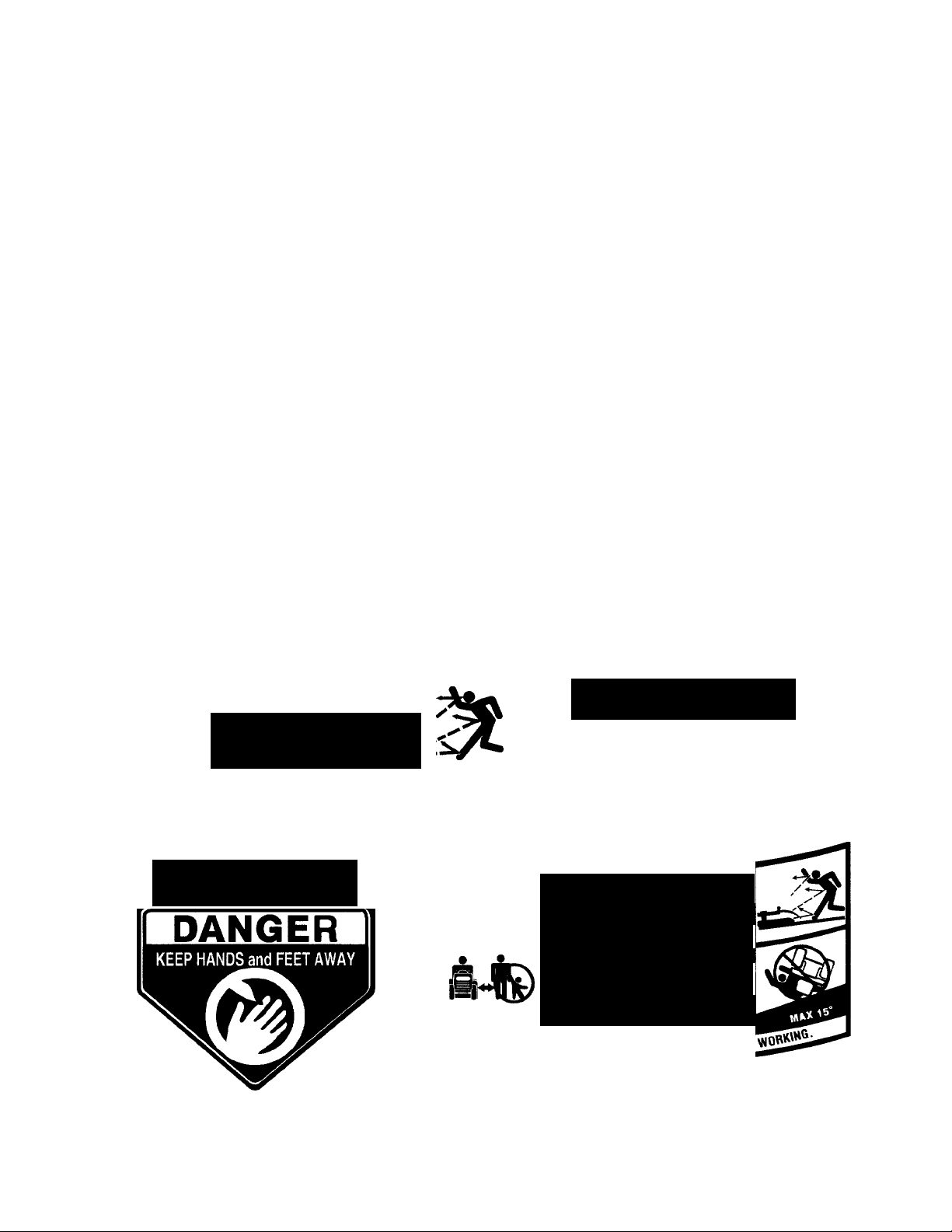
I adawgerT
KEEP HANDS AND FEET AWAY.
DO NOT OPERATE MOWER UNLESS
THIS GUARD OR ENTIRE GRASSCATCHER IS IN ITS PROPER PLACE.
ASSEMBLE CHUTE DEFLECTOR TO THIS UNIT BEFORE OPERATING
___________________________mm.
TO REDUCE THE RISK OF INJURY, DO NOT
OPERATE MOWER UNLESS REAR TRAILING
SHIELD AND THIS GUARD OR ENTIRE
GRASS CATCHER IS IN ITS PROPER PLACE.
A
ASSEMBLE CHUTE DEFLECTOR
BEFORE OPERATING MACHINE.
DANGER
TO THIS UNIT
A DANGER
Мою SERIOUS INJURY OR DEATH
* AMD FEET AWAY FROM
«ОТДТ/NG PARTS
* OBJECTS THAT CAN BE THROWN BY THE
* direction, wear SAFETY GLASSES,
00 WOT MOW WHEN CHILDREN OR OTHERS
ARE AROUND. NEVER CARRY CHILDREN.
OSE EXTRA CAUTION ON SLOPES. DO NOT MOW
greater than 15“ MOW UP AND OOWN^
ROTACROSS. avoid sudden turns, use low gear
■^^Onor».^ МДЦПД1 KEEP SAFETYDEVtCES
Figure 2 Safety labels found on your unit
5
Page 6
0)
U)
3
(0
uSE THIS PAGE AS A GUIDE TO DETERMINE SLOPEo WHERE YOU MAY NOT OPERATE SAFELY.
SIGHT AND HOLD THIS LEVEL WITH A VERTICAL TREE
----------A POWER POLE
---------------------A CORNER OF A BUILDING
--------------------------------OR A FENCE POST
CD
0)
Q.
O
C/)
CD
WARNING
▲
Do not mow on inclines with a slope in excess of 15 degrees (a rise of approximately 2-1/2 feet every 10 feet). A riding mower
could overturn and cause serious injury. If operating a walk-behind mower on such a slope, it is extremely difficult to maintain
your footing and you could slip, resulting in serious injury.
Operate RIDING mowers up and down slopes, never across the face of slopes.
Operate WALK-BEHIND mowers across the face of slopes, never up and down slopes.
Page 7
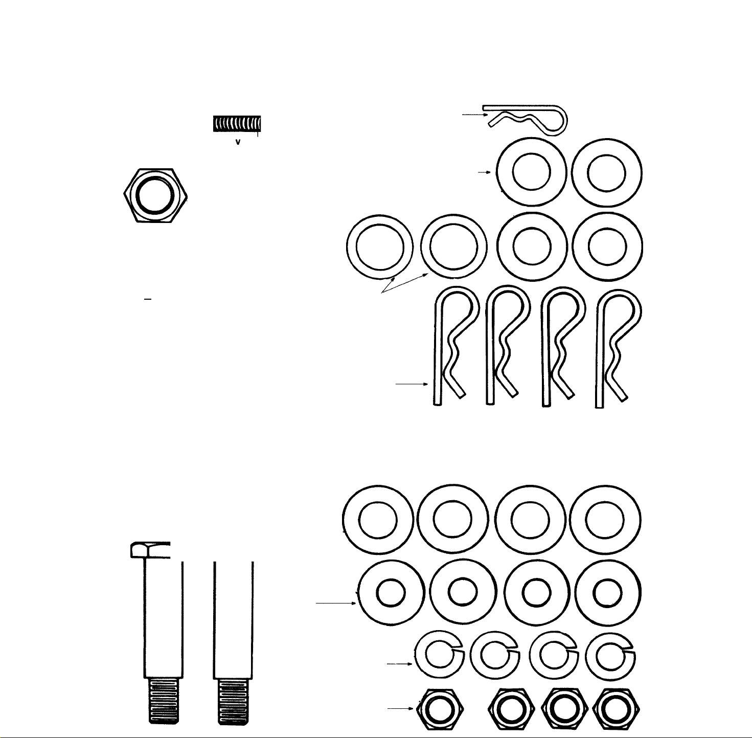
CONTENTS OF HARDWARE PACK
Hardware pack may contain extra items which are not used on your unit. Part numbers are shown in parentheses.)
A ATTACHING THE DECK LINKS
Co^
Eyebolts
(711-0817)
(Not Shown to
Scale) Quantity 3
Hex Nuts
1/2-13 Thread
(712-0206) Quantity 3
■mDD
C ATTACHING THE DECK WHEELS
(If not already attached)
rr^quu
(46" Deck
Deck
Wheels are
Not Shown
Only)
B ATTACHING THE CUTTING DECK
Small
Clevis Pin
(711-0701)
Spacers
(750-0932A)
Hairpin Clips
(714-0101)
Hairpin
Clip
(714-0104)
Flat
Washers
1/2" I.D.
(736-0192)
NOTE: This
hardware may
be assembled
to the deck
Front
Axle Bolts
3-1/4"
-----
Long
(738-3056)
Flat Washers
1/2" I.D.
(736-0192)
Cupped
Washers
3/8" I.D.
(736-0105)
Rear
Axle Bolts
2-1/4" Long
(738-0533)
Lock
Washers
3/8" I.D.
(736-0169)
Hex Nuts
3/8-16 —
Thread
(712-0798)
Page 8

SECTION 4: UNPACKING
TO REMOVE UNIT FROM CRATE
1. Remove all screws from the top of the crate
using a 1/4" hex head socket or a flat blade
screwdriver.
2. To remove ends, grasp top board on the end, and
pull towards you in a downward motion.
(A hammer may be helpful).
3. Set panel aside to avoid tire punctures.
4. Repeat procedure for each side of the crate.
5. Remove and discard plastic bag which covers
unit.
6. Loose parts (may include the owner's guide,
7. Remove the deck from beneath the tractor. Make
8. Remove page seven from this manual and lay
SECTION 5: ASSEMBLY INSTRUCTIONS
IMPORTANT: After assembly, service engine
with gasoiine, and check oii ievei as instructed
in the separate engine manuai packed with your
unit.
NOTE: Reference to right or ieft hand side of
the unit is observed from the driver’s seat, facing
forward.
TOOLS REQUIRED FOR ASSEMBLY
(1) 1/4" socket wrench or flat blade screwdriver
(1) 1/2" wrench or socket wrench*
(1) 9/16" wrench or socket wrench
(2) 7/16" wrenches or socket wrenches
*lf your steering wheel cap is square, you must have
a socket wrench in order to install the steering wheel.
BATTERY INFORMATION
D. Since battery acid is corrosive, do not pour it into
E. NEVER connect or disconnect charger clips to
F. Keep all lighted materials (cigarettes, matches,
G. As a further precaution, only charge the battery in
*Always shield eyes, protect skin and clothing
steering wheel, battery fluid, chute deflector,
etc.) are on the seat or in a box and wrapped in
plastic. Carefully cut and remove the plastic
wrap. Remove loose parts from the seat.
certain parking brake is released and unit is in
neutral. See the controls section of this manual
for location of the parking brake release and the
shift lever. Push unit off of the skid.
out the contents of the hardware pack according
to the illustration for identification.
any sink or drain. Before discarding empty elec
trolyte containers, rinse them with a neutralizing
solution.
battery while charger is turned on as it can cause
sparks.
lighters) away from the battery as the hydrogen
gas generated during charging can be combusti
ble.
a well-ventilated area.
when working near batteries.
A
A.
Battery acid must be handled with great care as
contact with it can burn and blister the skin. It is
also advisable to wear protective clothing (gog
gles, rubber gloves and apron) when working with
it.
B.
Should battery acid accidentally splatter into the
eyes or onto the face, rinse the affected area
immediately with clean cold water. If there is any
further discomfort, seek prompt medical atten
tion.
If acid spills on clothing, first dilute it with clean
water, then neutralize with a solution of ammonia/
water or baking soda/water.
WARNING
A
Battery contains sulfuric acid. Refer to warning
at right. Antidote: EXTERNAL—Flush with water.
INTERNAL—Drink large quantities of water or milk.
Follow with milk of magnesia, beaten eggs or
vegetable oil. Call physician immediately. EYES:
Flush with cool water for at least 15 minutes, then
get prompt medical attention.
Since batteries produce explosive gases, keep
all lighted materials (cigarettes, lighters,
matches, etc.) away. Be sure to charge battery
only in well-ventilated areas. Make certain venting
path of battery drain tube (if equipped) is always
open.
KEEP BATTERIES
OUT OF THE REACH OF CHILDREN!
DANGER
Page 9
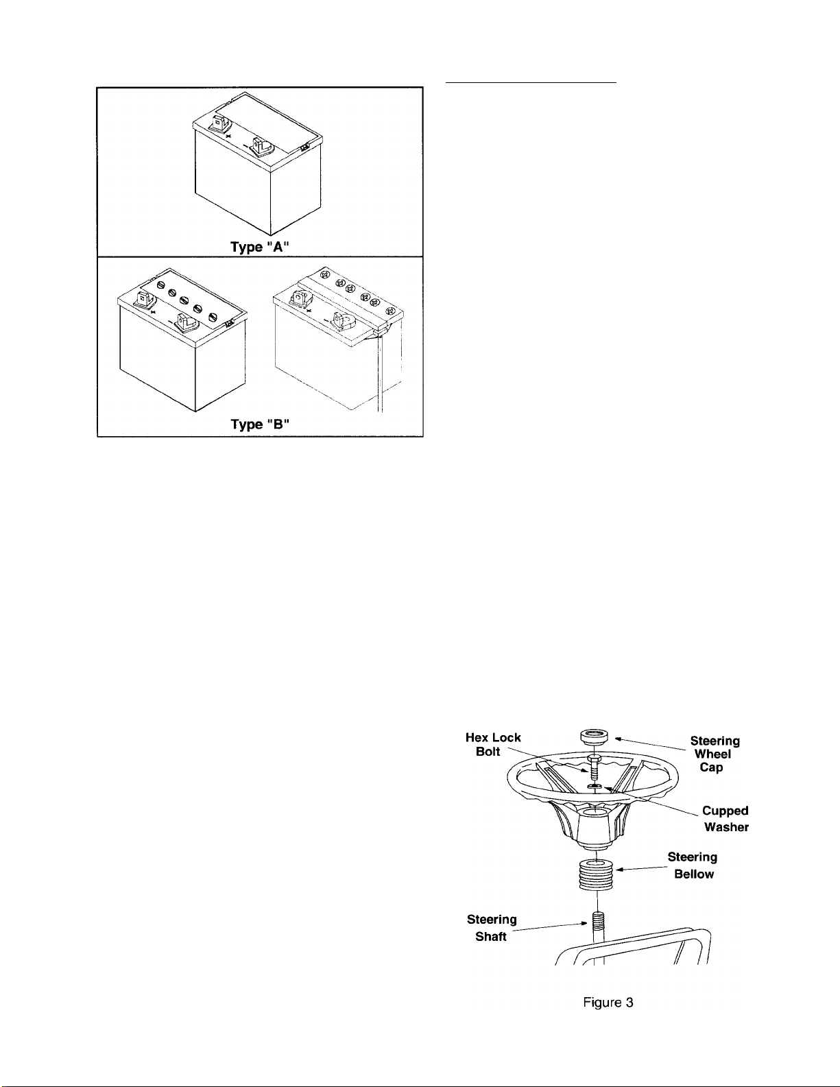
BATTERY IDENTIFICATION
Compare the battery in your lawn tractor (located
under the seat) with the illustration above. Type “A”
batteries are activated and are ready to use. Type
“B” batteries must be filled with battery fluid (acid)
and charged before they are put into service. Follow
the instructions which apply to the battery in your
lawn tractor.
ACTIVATING AND CHARGING THE BATTERY
(TYPE “B” BATTERY ONLY)
Do not activate battery (fill with battery acid)
until battery is actually placed in service. Be
certain to read previous battery warnings before
activating the battery.
1. Pivot the seat pivot bracket forward. Unhook the
strap which secures the battery (hook is on rear
frame, under fender). Disconnect the positive
cable from the positive terminal. Save the
hardware for reassembly.
2. Remove the battery from the lawn tractor, paying
attention to how the battery is placed in the unit,
and how the drain tube (attached to the battery)
is routed.
3. Activate the battery as instructed in the “Quick
Start” brochure included with the battery fluid.
Read instructions carefully.
NOTE: You can continue assembling the lawn
tractor while battery is standing for 30 minutes (after
filling with acid), and later while you are charging the
battery.
IMPORTANT: To obtain the maximum life from
your battery, it MUST BE CHARGED prior to
initial use.
CHARGE THE BATTERY after the 30 minute
standing period. Battery P/N 725-1705D—Charge at
2-3 amps for one hour. Battery P/N 725-1707D, 7250453G, 725-1750, 725-1706—Charge at 6 amps for
one hour.
NOTE: If you charge the battery at a lower AMP
rate, use a hydrometer to make sure the battery is
completely charged. The hydrometer should read
1.260 minimum at an electrolyte temperature of eo
li 0°F. DO NOT CHARGE AT MORE THAN 6
AMPS.
STEERING WHEEL INSTALLATION
1. The hardware for attaching the steering wheel
has been packed inside the steering wheel.
Carefully pry off the steering wheel cap and
remove the hardware.
2. Remove the steering bellow from the lift lever on
the right hand side of tractor. Place steering
bellow over the steering shaft extending through
the dash. See Figure 3.
NOTE: If the openings on each end of the steering
bellow are two different sizes, the smaller end goes
down against the dash of the tractor.
3. With the wheels of the tractor pointing straight
forward, place the steering wheel over the
steering shaft, positioning steering wheel as
desired.
4. Place the washer with the cupped side down
over the steering shaft. Secure with hex lock
bolt. See Figure 3.
NOTE: If your steering wheel cap is square, you
must use a socket wrench.
5. Place the steering wheel cap over the center of
the steering wheel and seat it with your hand.
Page 10
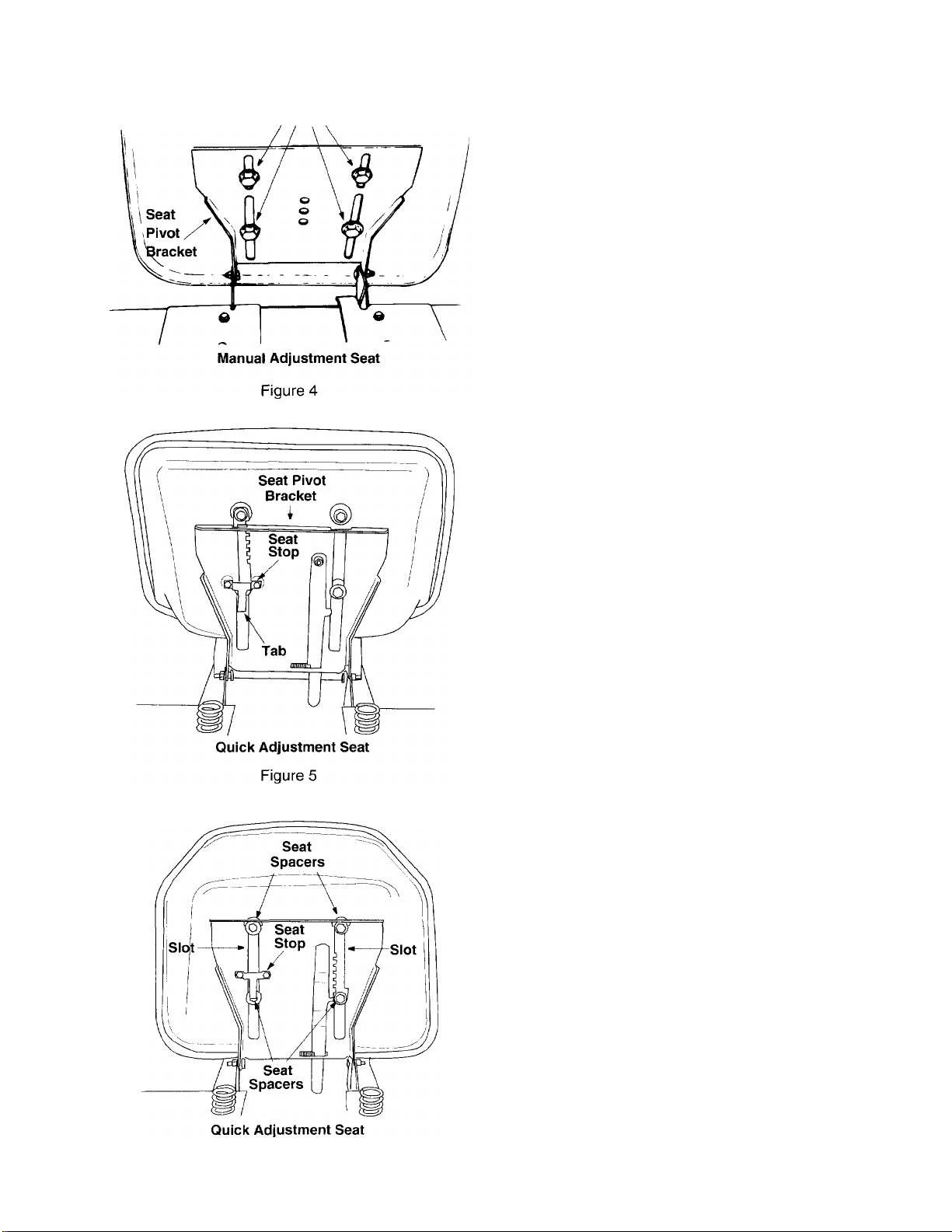
Screws
ATTACHING THE SEAT
There are two different seat pivot brackets used on
this series of garden tractor, a manual adjustment
seat or a quick adjustment seat. See Figure 4 and 5
to identify which seat is on your unit. Follow the
instructions which apply to your garden tractor.
MANUAL ADJUSTMENT SEAT
Remove the four screws which secure the seat to
the seat pivot bracket. Turn the seat around and
place in position against the seat pivot bracket, lining
up the slotted holes in the pivot bracket with the
holes in the seat. Select desired position for the
seat, and secure with the four screws. See Figure 4.
NOTE: Your seat may have been shipped in a
box. Remove the four screws from the bottom of
seat and place seat in position against the seat pivot
bracket. Follow the directions above to attach the
seat.
QUICK ADJUSTMENT SEAT
Pull out tab on seat stop and hold open while sliding
seat out of seat pivot bracket. See Figure 5. Turn the
seat around and line up plastic seat spacers with the
slots in seat pivot bracket. Slide seat in until front
seat spacer engages the seat stop. See Figure 6. To
adjust the seat refer to the adjustment section in this
manual.
NOTE: If your seat was shipped in a box, line up
plastic seat spacers with the slots in seat pivot
bracket and slide seat in until front seat spacer
engages seat stop.
WARNING: Before operating your unit,
stand behind quick adjustment seat and
A
pull back on seat, making sure seat is
engaged in seat stop.
Figure 6
10
Page 11
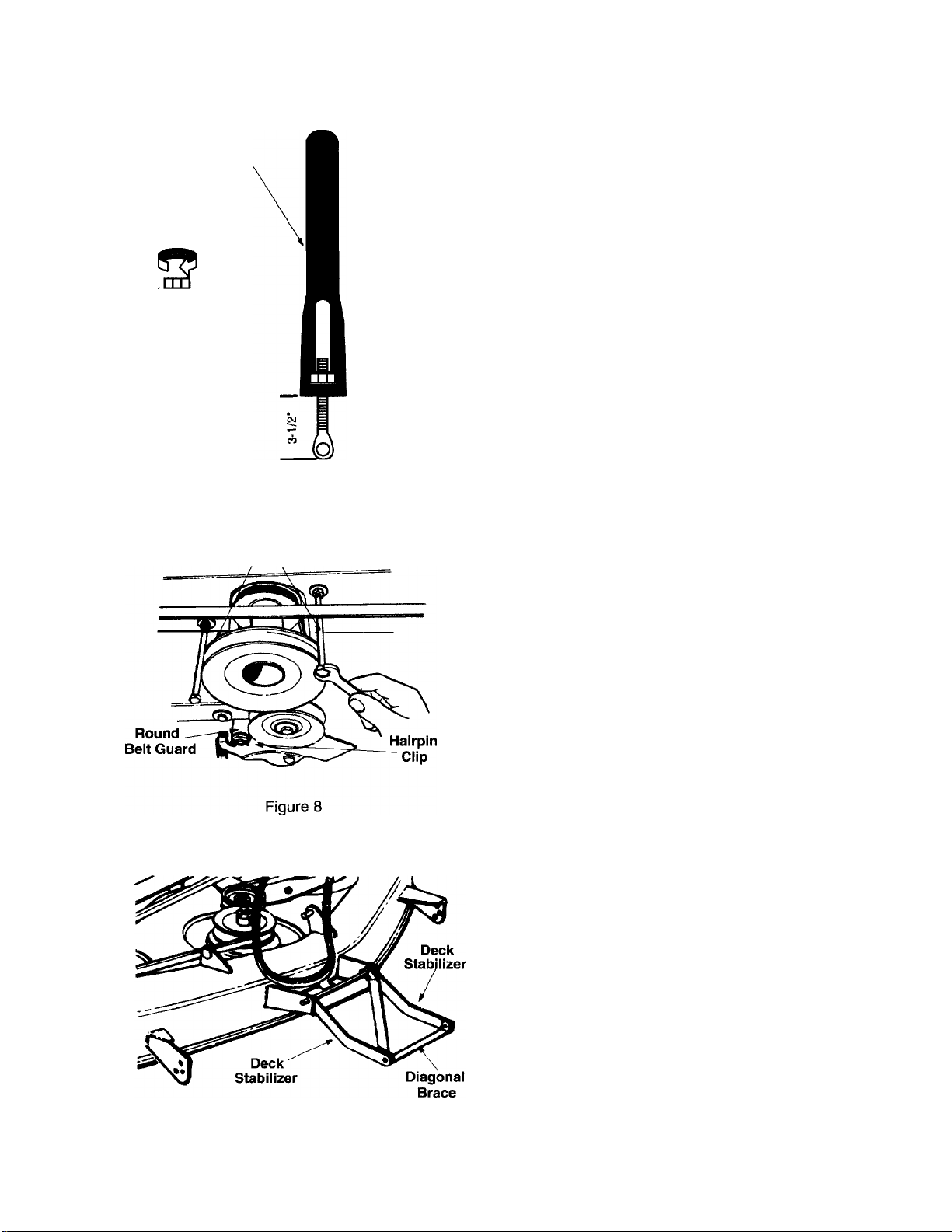
Setting for
Left Rear Link
Hex I
Nut
ATTACHING THE DECK LINKS (Hardware A)
The three adjustable deck links have been shipped
unassembled. Attach as follows.
1. Start 1/2" hex nuts on eyebolts until nuts are
flushed with ends of eyebolts. See Figure 7.
2. Insert eyebolts and hex nuts into the adjustable
lift links located under the tractor. See Figure 7.
3. Thread eyebolts into the lift links and hex nuts.
The left rear link should be adjusted so the
eyebolt hangs about 3-1/2 inches below the lift
link. The two front links should be adjusted so
the eyebolts hang about 2-1/8 inches below the
lift links. See Figure 7.
Eyeboit
6 o
Figure 7
Hex Boits
y
“ \
Setting for
Front Links
ATTACHING THE CUTTING DECK (Hardware B)
NOTE: The assistance of another person is helpful
when attaching the cutting deck.
1. Working beneath the tractor, remove the round
belt guard from the idler by removing the hairpin
clip. See Figure 8. Remove the two hex bolts
which act as belt keepers by the engine pulley.
2. Move the tractor lift handle all the way back to
the full raised position. Turn the tractor steering
wheel all the way to the right.
3. Units with 50" Decks: Remove the roller
assembly from the rear of the deck and set
aside.
4. The two deck stabilizers and the diagonal brace
which are attached to the front of the deck are
folded back over the deck for shipping purposes.
Unfold them at this time. See Figure 9.
5. Slide the deck under the tractor from the left
side. You may need to angle the deck slightly to
get the braces past the front wheel.
Figure 9
NOTE: When attaching the cross bar, reference to
the right or left hand side is observed facing the front
of the tractor.
6. Standing in front of tractor, remove the hairpin
clips from the cross bar.
7. Slide the cross bar to the left until the right side
is free. Drop bar down and slide to the right until
cross bar is removed from the tractor.
8. Insert cross bar through the two deck stabilizers
and the diagonal brace. See Figure 10A.
11
Page 12
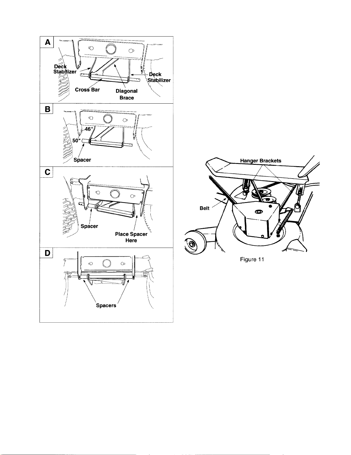
10. Place a spacer on the right end of the cross bar.
Pull the bar to the left until the spacer is flushed
with the end of the bar. Slide the cross bar into
the hole on the right side of frame. Secure with
hairpin clip. See Figure 10D.
11. Move the lift lever forward to the lowest position.
NOTE: It may be necessary to pull down on the lift
links to obtain the lowest position.
12. Lift up on the edge of the deck and hook up the
left front deck hanger to the deck using a flat
washer and hairpin clip. Make sure deck hanger
goes through the center of V-Belt. See Figure
11.
Figure 10
9. Place a spacer on the left end of the cross bar.
Pull the bar to the right until the spacer is flushed
with the end of the bar as shown in Figure 10B.
Lift assembly and slide the cross bar into one of
the holes on the left side of frame. Secure with
hairpin clip removed in step 6.
46" Deck: Use the rear set of holes.
50" Deck: Use the forward set of holes.
13. Attach the right front hanger to the deck using a
flat washer and hairpin clip.
14. Move the lift lever all the way back to the full
raised position.
15. Units with 50" Decks: Remove the clevis pins
and hairpin clips from the roller assembly. Slide
the roller assembly between the rear wheels and
the deck. Insert the deck roller brackets up
through the brackets provided on the rear of the
deck. It may be necessary to rotate the deck
roller brackets 360° to clear the roll pin stop.
Attach with clevis pins and hairpin clips just
removed, using the lowest hole location on each
side of the deck. See Figure 12.
16. Move the lift lever fonward to the lowest position.
17. Attach the two rear lift links with flat washers and
hairpin clips.
18. Place deck belt around the engine pulley. Make
certain the deck belt is seated in the deck pulley.
12
Page 13
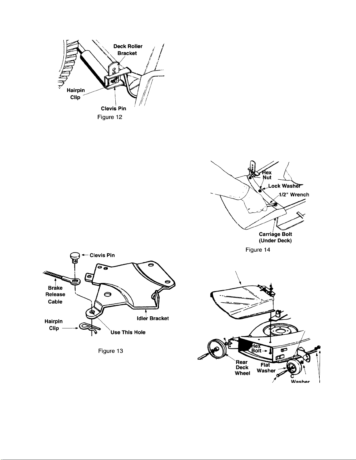
19. Push the idler bracket to the left and slip the belt
around the idler pulley. Replace the round belt
guard by the idler pulley (hex side down).
Secure with hairpin clip.
20. Replace the hex bolts (belt keepers) by the
engine pulley. Refer to Figure 8.
21. Check all belt guards for clearance. The belt
guards must be between 1/16" and 1/8" away
from the belt when the PTO lever is in the
engaged position (be certain to disengaged the
PTO lever after checking).
22. Secure the brake release cable to the tractor
idler bracket with clevis pin and small hairpin
clip, using the hole in the idler bracket as shown
in Figure 13.
ATTACHING THE DECK WHEELS (Hardware C)
(46" Deck Only)
If the deck wheels are not already attached, attach
the wheels to the deck as follows. All wheels must
be placed in the same relative position.
Front Wheels: Front axle bolts are the longer bolts.
Front deck wheels have a rounded surface.
Rear Wheels: Rear axle bolts are the shorter bolts.
Rear deck wheels are flatter.
Place flat washer 1/2" I.D. on axle bolt, then the deck
wheel and cupped washer (crowned side of washer
goes against the wheel). See Figure 15. Secure to
deck with lock washer and hex nut. Tighten securely.
Assemble remaining wheels in same manner.
ATTACHING THE CHUTE DEFLECTOR
WARNING: Do not operate the tractor
unless the chute deflector has been
A
Remove the bolts, nuts and cupped washers which
are attached to the deck next to the chute opening.
Place the chute deflector in position as shown in
Figure 14 and 15. Secure with hardware just
removed.
properly installed.
Hex Nut and
Lock Washer
Cupped Washer
\ Washer
Rear
Axle Bolt
(2-1/4" Long)
13
Chute Deflector
Flat
Cupped Washer
Front Axle Bolt
(3-1/4" Long)
Figure 15
Hex Nut and
Front
Deck
Wheel
upped
Washer
Hex Nut and
Lock Washer
Page 14
TIRE PRESSURE
The tires on your unit may be over-inflated for ship
ping purposes. Reduce the tire pressure before oper
ating the unit. Check the sidewall of the tires for
proper inflation pressure.
WARNING: Maximum tire pressure
under any circumstances is 30 p.s.i. Equal
Àk
tire pressure should be maintained on all
tires.
LEVELING THE DECK
After attaching the deck to the tractor, check to be
certain it is adjusted properly.
1. Check tire pressure in all four tires. See sidewall
of tire for recommended inflation pressure.
2. Make certain all deck wheels or both ends of the
deck roller are mounted in same relative hole
locations.
3. Place the tractor on a level surface.
4. 46" Deck; Lower the deck until it reaches the
ground. All four deck wheels should reach the
ground at the same time.
5. Both Decks: Place the deck approximately 1"
above the ground. Check to be certain the
distance from the bottom edge of the deck to the
ground is the same on both sides of the deck.
If adjustment is necessary, adjust the deck links on
the left side of the deck as follows.
1. Make certain the PTC is disengaged. Remove
the hairpin clip and washer from the weld bolt.
Thread eyebolt up or down the link as
necessary, and reassemble.
2. Check to be certain the front of the deck is 1/4"
to 3/8" lower than the rear of the deck. If it is not,
adjust the two front links to obtain this distance.
FINAL ASSEMBLY
Make certain all nuts and bolts are tightened
securely.
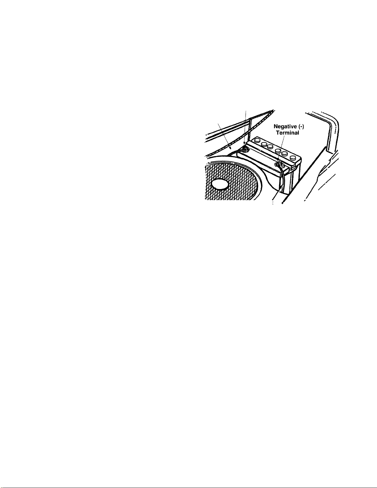
INSTALLING THE BATTERY (Type “A” Battery)
NOTE: If battery is put into service after date
shown on top of battery, charge for minimum of 1
hour at 6-10 amps.
2. Remove the plastic cover from the negative
terminal.
3.
Remove the hex bolt and nut from the negative
(black) cable. Attach negative cable to the
negative terminal with this bolt and nut.
4.
Place battery cover over battery and secure with
wing nuts removed in step 1.
Positive (+)
Red
Positive (+)
Cable
Terminal
BlacR
Negative
(-) Cable
Figure 16
NOTE: It may be necessary to pull up on the
hold-down rods in order to start the wing nuts.
INSTALLING THE BATTERY
(Type “B” Battery)
NOTE: The positive battery terminal is marked
Pos. (+). The negative battery terminal Is marked
Neg. (-).
1. Place the battery on the battery plate with the
terminals toward the front of the tractor.
2. Attach the positive cable (heavy red wire) to the
positive battery terminal (+) with hex bolt and
hex nut. See Figure 16. Slide the rubber boot
down over the positive terminal.
3. Remove the hex bolt and nut from the negative
cable. Attach the negative cable (heavy black
wire) to the negative battery terminal (-) with the
bolt and nut.
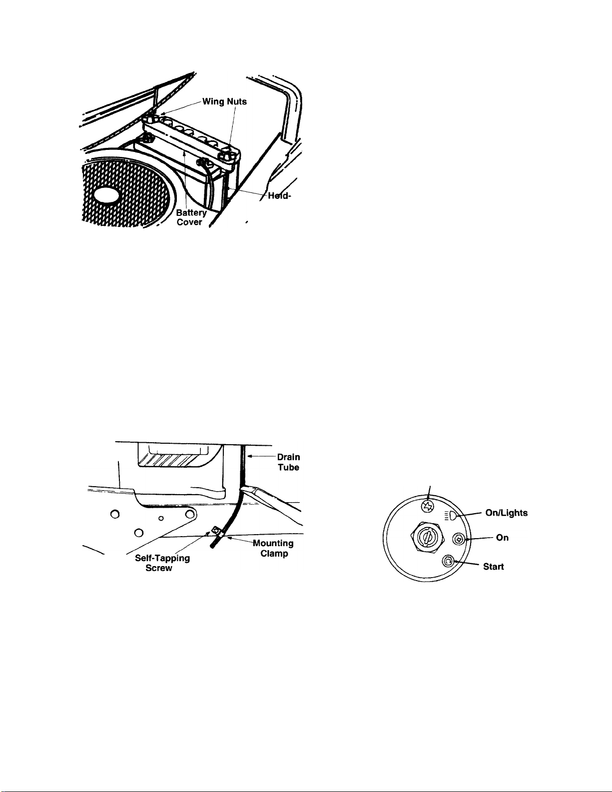
4. Place the battery cover in position over the hold
down rods. Secure with wing nuts. See Figure
17.
1. Lift the hood of the tractor. Remove the wing
nuts from the hold-down rods which secure the
battery cover to the battery. See Figure 16.
NOTE: It may be necessary to pull up on the hold
down rods in order to start the wing nuts.
14
Page 15
WARNING: Remove the key from the
tractor when the tractor is not in use to
dk
prevent accidental starting.
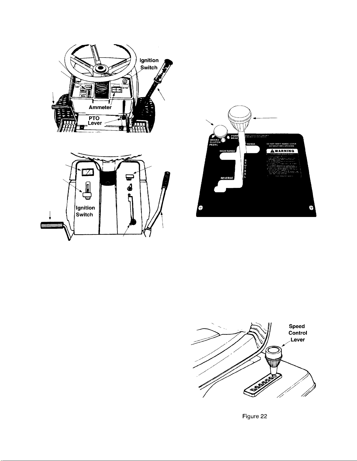
THROTTLE CONTROL
The throttle control is located on the left side of the
dashboard and is used to regulate the engine speed.
See Figure 20. The engine should be operated at full
throttle (FAST) when operating any equipment that
uses the tractor engine as a source of power such as
the mowing deck, snow thrower or rotary tiller.
Down
Rod
/
Figure 17
5. Route the battery drain tube over to the left side
of the tractor. Loosen the self-tapping screw
which secures the mounting clamp. See Figure
18. Slip the end of the drain tube into the
mounting clamp. Tighten the self-tapping screw
to secure the clamp. Do not overtighten which
could collapse the drain tube.
NOTE: The vented battery allows any gases or
liquid from the battery to be drained onto the ground.
6. Trim end of drain tube if more than 1 inch
extends below the frame.
CHOKE CONTROL
The choke control is located on the dashboard and
is operated manually. Details for the choke operation
are covered in the separate engine manual packed
with your unit. See Figure 20.
IGNITION/LIGHT SWITCH
To prevent accidental starting and/or battery
discharge, remove the key from the ignition switch
when the tractor is not in use.
To start engine insert key into ignition switch and
turn clockwise to the START position. Release key
to the ON position once engine has fired. The lights
are controlled by the ignition switch. After the tractor
is running, turn the key counterclockwise to the
LIGHTS ON position. See Figure 19.
WARNING: To prevent accidental
starting and/or battery discharge, remove
dk
the key from the ignition switch when the
tractor is not in use.
Off
Figure 18
SECTIONS: CONTROLS
IGNITION SWITCH
The ignition switch is located on the dashboard. The
engine is started by turning the key to the START
position. When the engine is running, leave the key
in the ON position. To stop the engine, turn the key
to the OFF position. See Figure 19 and 20.
Figure 19
AMMETER (Optional)
The ammeter registers the rate of battery charge or
discharge. The ammeter will register on the
discharging side when starting the engine. It should
register on the opposite side (charging) when the
engine is running in the fast position until the battery
is completely charged. With a fully charged battery
or with the engine idling, the ammeter will not show
a charge. See Figure 20.
15
Page 16
Choke
Throttle
Clutch-
Brake
Pedal
Models 820, 825, 840 and 845
Lift
Lever
PARKING BRAKE
To set the parking brake, depress the clutch-brake
pedal and pull up the parking brake knob. It will stay
in the raised position. To release the parking brake,
depress and release the clutch-brake pedal. See
Figure 21.
NOTE: The parking brake must be set if the
operator leaves the seat with the engine running.
Parking
Brake
Shift Lever
Ammeter
Throttle
Clutch-
Brake
Pedal
PTO
Lever
Models 82A and 84A
Choke
Lift
Lever
Figure 20
CLUTCH-BRAKE PEDAL
The clutch-brake pedal is located on the left side of
the tractor. See Figure 20. Depressing the clutchbrake pedal partway disengages the clutch. Pressing
the pedal all the way down disengages the clutch
and engages the disc brake.
NOTE: The clutch-brake pedal must be depressed
to start the engine.
Figure 21
SPEED CONTROL LEVER
The speed control lever is located on the left fender.
It allows you to regulate the ground speed of the
garden tractor. See Figure 22. To select the ground
speed, depress clutch pedal. Push speed control
lever outward and move backward to slow garden
tractor, move forward to increase speed. When
desired speed has been obtained, release lever in
that position. Whenever clutch is engaged, unit will
automatically go to the pre-set speed.
SHIFT LEVER
The shift lever is located in the center of the console
and has four positions, HIGH, LOW, NEUTRAL and
REVERSE. See Figure 21. The clutch-brake pedal
must be depressed and the garden tractor must not
be moving when shifting gears. Do not force the shift
lever. Release the clutch-brake pedal slightly to line
up the shifting collar in the transmission. Then try to
shift gears.
16
Page 17

LIFT LEVER
The five position iift lever is used to change the
operating position of the attachments. To operate,
pull the lever towards you. To release, move the
lever to the right and then forward. See Figure 20.
POWER TAKE-OFF (PTO) LEVER
The PTO lever is located on the right side of the
dashboard. The PTO lever is used to engage and
disengage the power to the attachments. To engage
the PTO, lift the lever slowly and lock it into the notch.
See Figure 20.
NOTE: The PTO lever must be in the disengaged
position (down) when starting the engine, when
shifting into reverse and if the operator leaves the
seat.
WARNING: Never fill fuel tank indoors,
with engine running or while engine is hot.
A
STARTING THE ENGINE
IMPORTANT: This unit is equipped with a safety
interlock system for your protection. The purpose
of the safety interlock system is to prevent the
engine from cranking or starting unless the clutchbrake pedal is depressed and the PTO lever is in the
disengaged position. In addition, the PTO lever must
be in the disengaged position when the unit is put
into reverse or the engine will shut off. If the operator
leaves the seat with the PTO lever engaged and/or
without setting the parking brake, the engine will
shut off.
SECTION?: OPERATION
A
AVOID SERIOUS INJURY OR DEATH
GO UP AND DOWN SLOPES, NOT ACROSS. «AVOID SUD
DEN TURNS.
DO NOT OPERATE THE UNIT WHERE IT COULD SLIP OR
TIP.
IF MACHINE STOPS GOING UPHILL, STOP BLADE(S) AND
BACK DOWNHILL SLOWLY.
DO NOT MOW WHEN CHILDREN OR OTHERS ARE
AROUND.
NEVER CARRY CHILDREN.
LOOK DOWN AND BEHIND BEFORE AND WHILE BACK
ING.
KEEP SAFETY DEVICES (GUARDS, SHIELDS, AND
SWITCHES) IN PLACE AND WORKING.
REMOVE OBJECTS THAT COULD BE THROWN BY THE
BLADE(S).
KNOW LOCATION AND FUNCTION OF ALL CONTROLS.
BE SURE BLADE(S) AND ENGINE ARE STOPPED BEFORE
PLACING HANDS OR FEET NEAR BLADE(S).
BEFORE LEAVING OPERATOR'S POSITION, DISENGAGE
BLADE(S), PLACE THE SHIFT LEVER IN NEUTRAL,
ENGAGE BRAKE LOCK, SHUT ENGINE OFF AND REMOVE
KEY.
READ OPERATOR’S MANUAL
WARNING
WARNING: Do not operate the tractor if
the interlock system is malfunctioning
A
1. Place the PTO lever in the disengaged (down)
2. Depress the clutch-brake pedal and set the
3. Place the shift lever in the NEUTRAL position.
4. Set the throttle control in the FAST position.
5. Pull out the choke control (a warm engine may
6. Turn the ignition key to the right to the START
7. Slowly push in the choke as the engine warms
because it is a safety device, designed for
protection.
position.
parking brake.
not require choking).
position. After the engine starts, release the key.
It will return to the ON position.
up.
STOPPING THE ENGINE
Turn the ignition key to the left to the OFF position.
Remove the key to prevent accidental starting.
GAS AND OIL FILL-UP
Check oil level and add if necessary. Service the
engine with gasoline as instructed in the
separate engine manual packed with your
tractor. Read instructions carefully.
IMPORTANT: Your tractor is shipped with oii;
however, you must check the oil level before
operating. Be careful not to overfill.
The gasoline tank is located under the seat. The
filler neck is behind the seat. Do not overfill.
IMPORTANT: If you strike a foreign object, stop
the engine. Remove wire from spark plug, thoroughly
inspect the unit for any damage, and repair the dam
age before restarting and operating the mower.
NOTE: If any problems are encountered, refer to
the Trouble Shooting Guide.
SETTING THE CUTTING HEIGHT
Select the position for the tractor lift lever which
gives the desired cutting height. Then move the
wheels on the deck so that the wheels are 1/4 to 1/2
inch above the ground.
17
Page 18

NOTE: To obtain the best, uniform cut, the deck is
designed to be suspended from the tractor at the
desired cutting height. The deck wheeis or deck
rolier should be just off the ground, to smooth out the
cut and guard against gouging.
OPERATING THE TRACTOR
1. Start the engine as instructed previously.
2. Move throttle control to full throttle to prevent
strain on the engine and to operate attachments.
3. Place the shift lever in one of the two forward
positions (LOW or HIGH), or in REVERSE.
Place the speed control lever in desired position.
Use first speed position when operating the
tractor for the first time.
WARNING: Look to the rear before
backing up.
dk
4. Release the parking brake by depressing the
clutch-brake pedal. Release clutch-brake pedal
slowly to put unit into motion.
5. The tractor is brought to a stop by depressing
the clutch-brake pedal.
6. The cutting blades (or other attachment) may be
engaged while the tractor is moving or standing
still. DO NOT engage the cutting blades abruptly
as the sudden belt tension on the pulley may
cause the engine to stall.
WARNING: Keep feet and hands away
from the discharge opening, the blades or
dk
NOTE: When operating the unit initially, there will
be little difference between the highest two speeds
until after the belts have seated themselves into the
pulleys during the break-in period. Be certain to
change oil in the crankcase after the first 5 hours of
operation.
any part of the deck.
also eliminate “browning” the grass, which is caused
by hot exhaust gases from a running engine.
If unit stalls with speed control in sixth or seventh
speed, or if unit will not operate with speed control
lever in first or second speed position, proceed as
follows.
1. Place shift lever in NEUTRAL.
2. Restart engine.
3. Place speed control lever in highest speed
position.
4. Release clutch-brake pedal fully.
5. Depress clutch-brake pedal.
6. Place speed control lever in desired position.
7. Place shift lever in one of the forward positions
(HIGH or LOW) or REVERSE, and follow normal
operating procedures.
HIGH-LOW TRANSMISSION RANGES
HIGH range position is for normal load conditions,
such as mowing or transporting.
LOW range position is for situations which require
more torque when the tractor is used under high
load conditions, such as tilling, snow removal or
hauling heavy loads.
GRASS COLLECTOR AVAILABLE
GRASS COLLECTOR Model 190-083 is available as
optional equipment for tractors with 46" mowing
decks.
WARNING: The mower should not be
operated without the entire grass catcher
dk
or chute deflector in place.
NOTE: Under normal usage bag material is
subject to wear, and should be checked periodically.
Be sure to use only factory authorized replacement
bag.
Be sure that the lawn is clear of stones, sticks, wire,
or other objects which could damage tractor or
engine. For best results and to insure more even
grass distribution, do not mow when lawn is
excessively wet.
WARNING: Before leaving the
operator’s position for any reason,
dk
When stopping the unit to empty a grass bag, etc.,
follow the instructions above. This procedure will
disengage the blades, place the shift lever
in neutral, engage the parking brake, shut
engine off and remove the key.
SECTIONS: ADJUSTMENTS
WARNING: Disconnect the spark plug
wire(s) and ground against the engine
dk
LEVELING THE DECK
The sides of the deck should be the same distance
from the ground. The front of the deck should be 1/4"
to 3/8" lower than the rear of the deck. If adjustment
is required, refer to “Leveling the Deck” in Assembly
Instructions.
18
before performing any adjustments, repairs
or maintenance.
Page 19
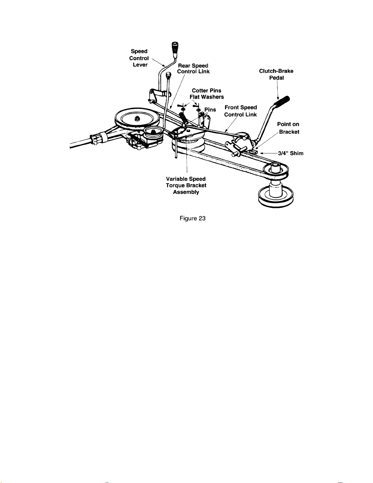
SPEED CONTROL ADJUSTMENT (See Figure 23)
NOTE: When operating the unit initiaily or after
replacing the belts, there will be little difference
between the highest two speeds until after the belts
have gone through a break-in period and have
seated themselves into the pulleys.
If speed control adjustment is needed, adjust the
speed control links as follows. (A 3/4" shim or
suitable spacer is required.)
1. Start the engine.
2. Place the shift lever in NEUTRAL position.
3. Place the speed control lever in highest speed
position.
4. Release the clutch-brake pedal completely, then
slowly depress the pedal all the way (to park
position). Hold the pedal in this position.
5. Turn the engine off.
6. After engine stops completely, release the
clutch-brake pedal.
7. Remove the transmission cover by removing the
parking brake knob, shift knob and two truss
machine screws.
8. Disconnect the rear speed control link from the
variable speed torque bracket by removing the
cotter pin and flat washer.
19
9.
Models 820 thru 829: Place the speed control
lever in the first position.
Models 840 thru 849: Place the speed control
lever in the second position.
10.
Disconnect the front speed control link from the
variable speed torque bracket by removing the
cotter pin and flat washer.
11.
Place a 3/4" shim or other suitable object under
the point on the bracket on the clutch-brake
pedal as shown.
12.
Thread the front speed control link in or out of
the ferrule until the hole in the link lines up with
the pin on the variable speed torque bracket.
Secure with the flat washer and cotter pin
removed in step 10.
13.
Push the rear speed control link backward using
light pressure, and hold it in this position as you
thread it into or out of the ferrule until the hole in
the link lines up with the pin on the variable
speed torque bracket.
Models 820 thru 829 Only: Turn the link three
more times (making it longer).
14.
Move the speed control lever toward the right so
the hole in the rear speed control link fits over
the pin on the variable speed torque bracket.
Secure with the flat washer and cotter pin
removed in step 8.
Remove the 3/4" shim from beneath the bracket
15.
on the clutch-brake pedal.
Page 20
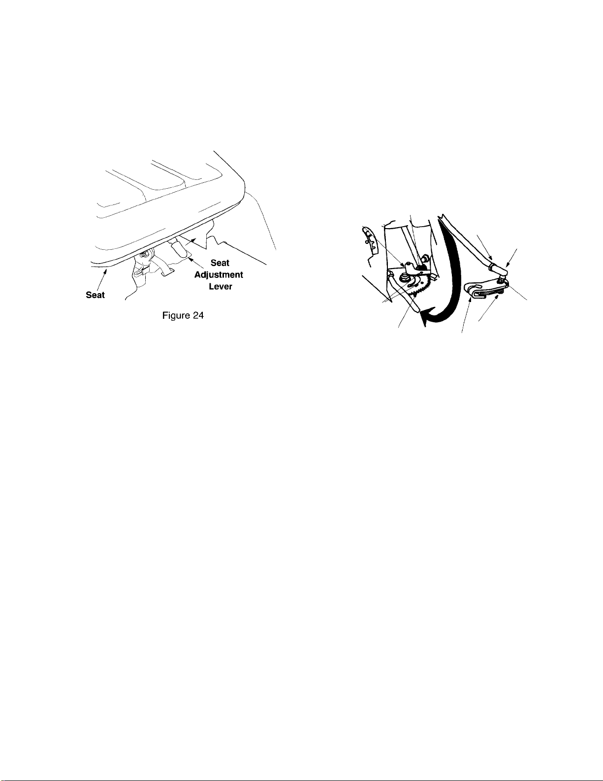
QUICK ADJUSTMENT SEAT
To adjust the position of the seat, move the seat
adjustment lever (located under the seat) to the left
and slide the seat forward or backwards. See Figure
24. Make sure seat is locked into one of the six
adjustment positions before operating the garden
tractor.
8. Tighten hex jam nut (A) against the ball joint.
9. Reattach the ball joint to the steering arm with
hex nut (B). Finger tighten only at this time.
10. Turn the steering wheel fully to the left and the
right to make sure that the drag link does not
touch any part of the tractor frame. If the drag
link does touch, start at step 1 and redo the
adjustment.
11. Tighten hex nut (B).
12. Remove the nail used to align the steering gear.
MANUAL ADJUSTMENT SEAT
To adjust the position of the seat, loosen the four
screws on the bottom of the seat. See Figure 4.
Slide the seat forward or backward as desired.
Retighten the four screws.
STEERING ADJUSTMENT
If the tractor turns tighter in one direction compared
to the other, the steering drag link must be adjusted.
To adjust the drag link follow these steps. Refer to
Figure 25.
1. Loosen hex jam nut (A) at the rear of the ball
joint.
2. Loosen and remove hex nut (B).
3. Lift the threaded portion of the ball joint out of
the steering arm. Please do not misplace the
hardware used to hold ball joint to steering arm.
You will need it again.
4. Set the front wheels facing straight ahead.
5. Turn the steering wheel to the right or the left to
match the alignment holes in the steering brace
and the steering gear.
6. Once aligned, drop a nail through the steering
brace and steering gear alignment holes.
7. Adjust the ball joint in or out on the drag link until
the threaded portion of the ball joint slips through
the hole in the steering arm. Make sure lock
washer (C) is in position between the ball joint
and the steering arm.
Steering P>ace Nail Here
Brace -
Alignment
Holes
Steering Gear
Figure 25
^rag Link
Hex Jam Nut (A)
Ball.Joint
Lock
Hex Nut (B)
Steering Arm
BRAKE ADJUSTMENT
The brake is located on the right side of the
transaxle. During normal operation of this machine,
the brake is subject to wear and will require periodic
examination and adjustment. To see if brake needs
adjusting proceed as follows.
WARNING: Do not adjust the brake
while the engine is running. Be sure to
A
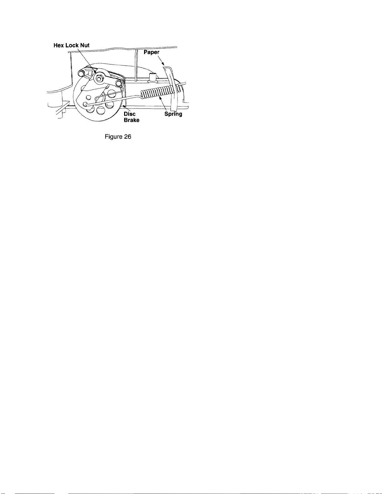
1. Set the parking brake by depressing the clutch-
2. Working on the right side of the tractor, try
3. If the paper can be inserted through the coils of
4. If the paper cannot be inserted, tighten the hex
5. Release the parking brake and place the tractor
block the wheels of the tractor before
making the brake adjustment.
brake pedal and pulling up the parking brake
knob.
inserting a piece of paper through the coils of the
brake spring. See Figure 26.
the brake spring, the brake is properly adjusted.
lock nut until the paper can be inserted through
the coils.
in neutral. Depress the clutch-brake pedal and
try rolling the tractor. The tractor should not
move. If the tractor moves, repeat the above
steps until proper brake adjustment is achieved.
20
Page 21
CARBURETOR ADJUSTMENTS
WARNING: If any adjustments are
made to the engine while the engine is
A
running (e.g. carburetor), disengage all
clutches and blades. Keep clear of all
moving parts. Be careful of heated
surfaces and muffler.
LINKAGE
Once a season lubricate all the pivot points on the
clutch, brake and lift linkage with SAE 30 engine oil.
WHEELS
The front wheels may be provided with grease
fittings. Lubricate at least once a season with
automotive multi-purpose grease.
PIVOT POINTS
Lubricate all pivot points with light oil at least once a
season.
BALL JOINTS
The ball joints and drag link ends are permanently
lubricated.
BLADE SPINDLES
The blade spindles on the cutting deck are
permanently lubricated.
SECTION 10: MAINTENANCE
Minor carburetor adjustments may be required to
compensate for differences in fuel, temperature,
altitude and load. Refer to separate engine manual
for carburetor adjustment information.
NOTE: A dirty air cleaner will cause an engine to
run rough. Be certain air cleaner is clean and
attached to
carburetor.
the carburetor before adjusting
SECTIONS: LUBRICATION
WARNING: Always stop engine and
disconnect spark plug wire(s) before
A
STEERING GEARS
Lubricate teeth of steering gears with automotive
multi-purpose grease after every 25 hours of
operation or once a season. Refer to Figure 25.
STEERING SHAFT
Lubricate steering shaft at least once a season with
light oil.
TRANSAXLE
The transaxle is lubricated and sealed at the factory
and does not require checking. If disassembled for
any reason, lubricate with 32 oz. of Shell Darina
grease, part number 737-0148 (16 oz. tube).
cleaning, lubricating or doing any kind of
work on garden tractor.
WARNING: Disconnect the spark plug
wire(s) and ground against the engine
A
before performing any adjustments, repairs
or maintenance.
TROUBLE SHOOTING
Refer to the trouble shooting chart for information.
ENGINE
Refer to the separate engine manual for engine
maintenance instructions.
Maintain engine oil as instructed in the separate
engine manual packed with your unit. Read and
follow instructions carefully.
Service air cleaner every 25 hours under normal
conditions. Clean every few hours under extremely
dusty condition. To service the air cleaner, refer to
the separate engine manual packed with your unit.
The spark plugs should be cleaned and the gap
reset once a season. Spark plug replacement is
recommended at the start of each mowing season;
check engine manual for correct plug type and gap
specifications.
CLEANING ENGINE AND DECK
Any fuel or oil spilled on the machine should be
wiped off promptly. Grass, leaves, and other dirt
must not be allowed to accumulate around the
cooling fins of the engine or on any part of the
machine.
Clean the underside of the deck after each mowing.
21
Page 22
CUTTING BLADES
WARNING: Protect hands by using
heavy gloves or a rag to grasp the cutting
dk
The blades may be removed for sharpening or
replacement as follows:
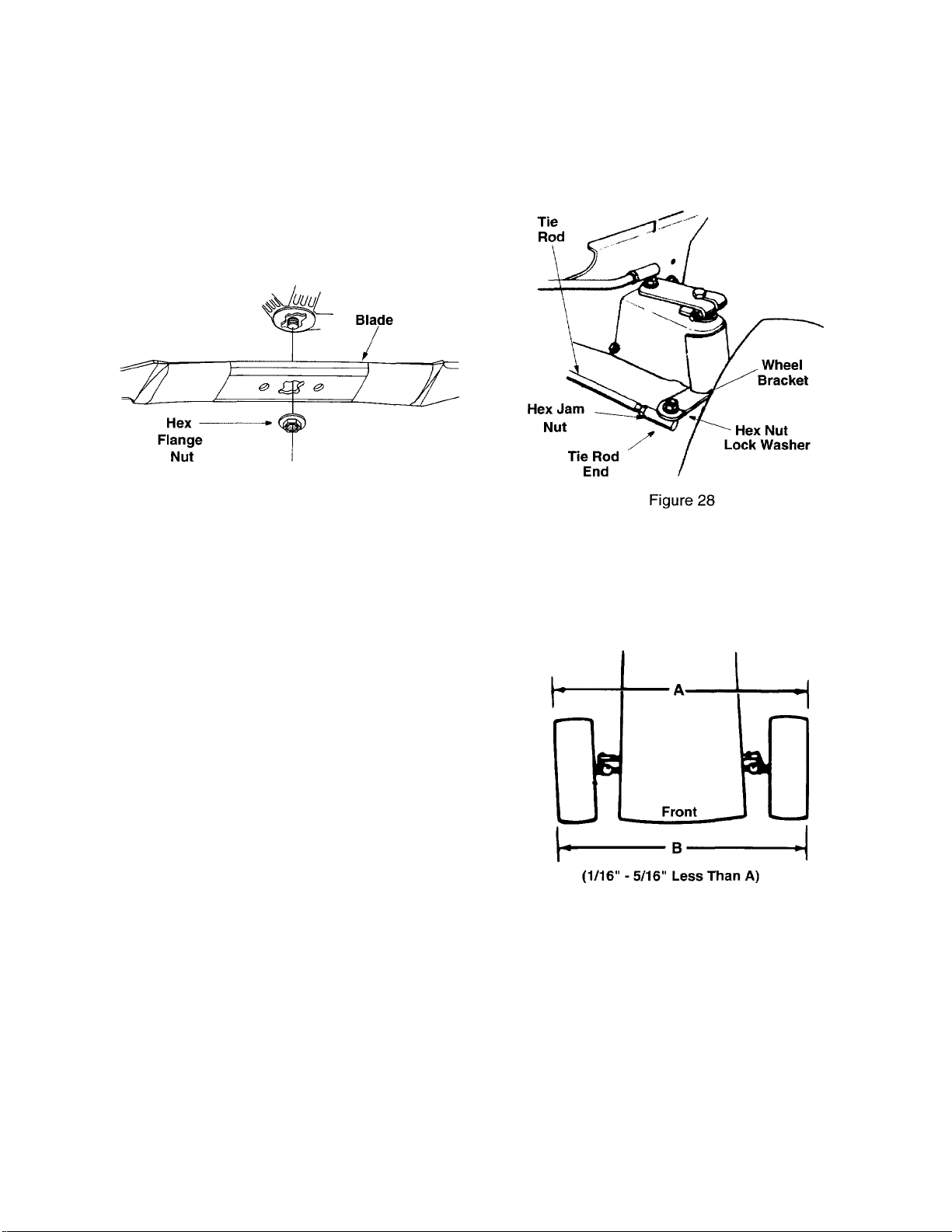
Remove the hex flange nut that holds the blade to
the blade spindle. See Figure 27.
When sharpening the blades, follow the original
angle of grind as a guide. It is extremely important
that each cutting edge be ground equally to prevent
an unbalanced blade. An unbalanced blade will
cause excessive vibration when rotating at high
speeds, may cause damage to the mower and could
break, causing personal injury.
blades.
Figure 27
Remove the hex nut and lock washer, and drop
the end of the tie rod from the axle bracket. See
Figure 28.
2.
Loosen the hex jam nut on tie rod.
3.
Adjust the tie rod assembly for correct toe-in.
Dimension “B” should be approximately 1/16-5/16"
less than Dimension “A.” See Figure 29. To increase
Dimension “B,” screw tie rod into tie rod end. To
decrease Dimension “B,” unscrew tie rod from tie rod
end. Reassemble tie rod. Check dimensions. Read
just if necessary.
The blade can be tested for balance by balancing it
on a round shaft screwdriver. Remove metal from
the heavy side until it balances evenly.
When replacing the blade, be sure to install the
blade with the side of the blade marked “Bottom” (or
with part number) facing the ground when the mower
is in the operating position.
TORQUE SPECIFICATIONS
Blade
Hex Flange Nut: 840 in. lb. min., 1080 in. lb. max.
Blade Spindle Screws
If disassembled for any reason, tighten the blade
spindle screws between 200 and 275 inch pounds.
WHEEL ADJUSTMENT
The caster (forward slant of the king pin) and the
camber (tilt of the wheels out at the top) require no
adjustment. Automotive steering principles have
been used to determine the caster and camber on
the tractor. The front wheels should toe-in between
1/16-5/16 inch.
Some units have adjustable tie rods so the toe-in
can be adjusted. To adjust the toe-in on these units,
follow these steps.
Figure 29
BATTERY CARE AND MAINTENANCE (TYPE "A" BATTERY)
Type “A” batteries are sealed and are maintenance
free.
BATTERY CARE AND MAINTENANCE (TYPE "B" BATTERY)
CHECK FLUID LEVEL
Check fluid level inside each cell of the battery every
two weeks and before and after charging. Always
keep level just below the split rings.
22
Page 23
Add only distilled water. Never add additional
acid or any other chemicals to the battery after initial
activation.
NOTE: After operating the tractor for a long period
of time, check the fluid level in the battery as it can
overheat and lose fluid.
CHARGiNG THE BATTERY (Ali Batteries)
The engine is equipped with an alternator which
charges battery when tractor is operated. Under
normal conditions, the battery only needs to be
charged before, during and after off-season storage.
Follow the instructions under “Off-Season Storage.”
To charge the battery: Battery P/N 725-1705D—
Charge at 2-3 amps for one hour. Battery P/N 725-
1707D, 725-0453G, 725-1750, and 725-1706-
Charge at 6 amps for one hour.
REMOVING / INSTALLING / JUMP STARTING
WARNING: When removing or
installing the battery, follow these
A
Removing the Battery: Disconnect negative cable
first, then positive cable.
Installing the Battery: Connect positive cable first,
then negative cable.
Jump Starting
1. First, connect end of one jumper cable to the
2. Connect the other jumper cable to the negative
instructions to prevent the screwdriver from
shorting against the frame.
positive terminal of the good battery, then the
other end to the positive terminal of the dead
battery.
terminal of the good battery, then to the FRAME
OF THE UNIT WITH THE DEAD BATTERY.
WARNING: Failure to use this
procedure could cause sparking, and the
Àk
gas in either battery could explode.
BATTERY FAILURES
Some common causes for battery failure are:
incorrect initial activation, lack of water, adding
chemicals other than water after initial activation,
undercharging, overcharging, corroded connections,
freezing. These failures do not constitute
warranty.
TIRES
Maximum tire pressure under any circumstances is
30 p.s.i. Equal tire pressure should be maintained on
all tires. Check tire sidewalls for proper inflation.
When installing a tire to the rim, be certain rim is
clean and free of rust. Lubricate both the tire and rim
generously. Never inflate to over 30 p.s.i. to seat
beads.
WARNING: Excessive pressure (over
30 p.s.i.) when seating beads may cause
A
tire/rim assembly to burst with force
sufficient to cause serious injury.
FUEL FILTER
Your unit is equipped with a replaceable in-line fuel
filter. Replace filter whenever contamination or
discoloration is noticed. Order replacement filter
through your authorized engine service dealer.
BELT REPLACEMENT
Deck Belt
1. Remove the deck by following instructions on
pages 11 thru 13 in reverse order.
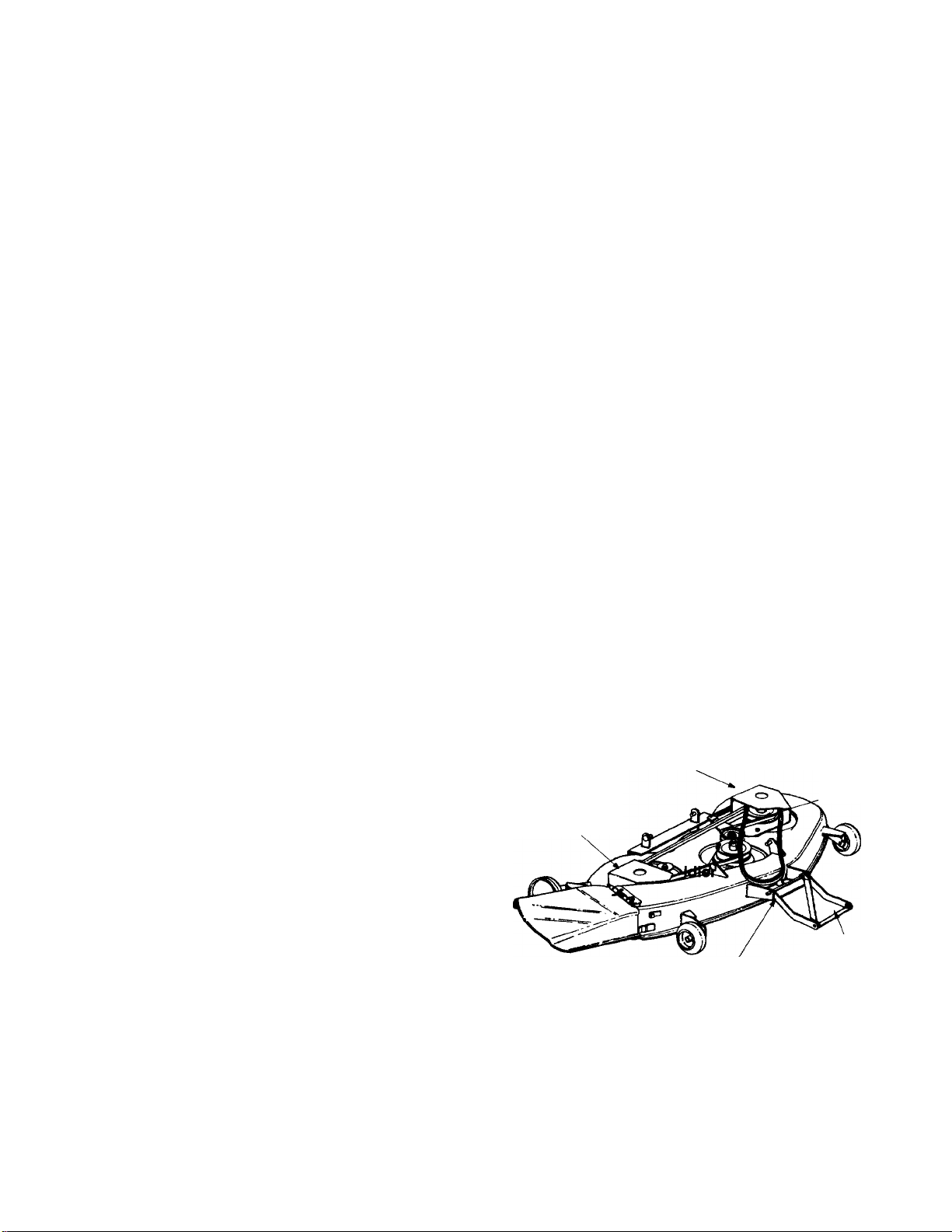
Left Hand
Pulley Cover
Belt
Right Hand
Pulley Cover
Guard
CLEAN THE BATTERY
Clean the battery by removing it from the unit and
washing with a baking soda and water solution. If
necessary, scrape the battery terminals with a wire
brush to remove deposits. Coat terminals and
exposed wiring with grease or petroleum jelly to pre
vent corrosion.
23
Diagonal
Deck Stabilizer
Figure 30
2.
Remove the left hand pulley cover by unhooking
the spring and removing five self-tapping
screws. See Figure 30.
Brace
Page 24
3. Remove the first drive belt.
4. Remove the right hand pulley cover by removing
three self-tapping screws.
5. Pivot the spring-loaded idler, and lift belt off.
6. Remove the belt from around the three deck
pulleys.
7. Reassemble new belts in reverse order.
Front Drive Belt
1. Depress the clutch pedal and set parking brake.
2. Remove the deck from the tractor.
Raise and block the front wheels of the tractor
so you can work under it.
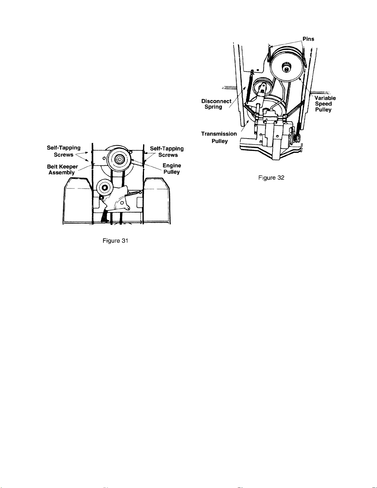
4.
Remove the four self-tapping screws which hold
the belt keeper assembly to the frame at the
engine pulley. Push the belt keeper assembly
forward, out of the way. See Figure 31.
5.
Remove the two pins which act as belt keepers
by the variable speed pulley. See Figure 32.
Roll the belt off the variable speed pulley, then
6.
remove from the engine pulley.
7. Reassemble the new belt, following instructions
in reverse order.
Rear Drive Beit
1. First remove the front drive belt as instructed in
the previous section.
2.
Disconnect the spring which secures the idler
pulley to the frame.
Remove the transmission cover by unscrewing
3.
the two knobs, and removing two truss machine
screws.
4. Roll the belt over the top of the transmission
pulley. Remove belt from the variable speed
pulley.
5. Reassemble the new belt, following instructions
in reverse order.
SECTION 11: OFF-SEASON STORAGE
If the machine is to be inoperative for a period longer
than 30 days, prepare for storage as follows.
1. Clean the engine and the entire unit thoroughly.
2. Lubricate all lubrication points. Wipe the entire
machine with an oiled rag to protect the
surfaces.
3. Refer to the engine manual for correct engine
storage instructions. The engine must be
completely drained of fuel and a fuel stabilizer
used to prevent gum deposits from forming on
essential carburetor parts, fuel lines and fuel
tanks.
4. Charge battery fully. The battery loses some of
its charge each day when the unit is not used.
NEVER store battery without a full charge.
Recharge battery before returning to service or
every two months, whichever occurs first.
5. When storing unit for extended periods,
disconnect battery cables. Removing battery
from unit is recommended.
6. Store unit in a clean, dry area. Do not store next
to corrosive materials, such as fertilizer.
NOTE: When storing any type of power equipment
in an unventilated or metal storage shed, care
should be taken to rustproof the equipment. Using a
light oil or silicone, coat the equipment, especially
any chains, springs, bearings and cables.
24
Page 25

SECTION 12: OPTIONAL EQUIPMENT
At the time of manufacture of tractor, the following optional equipment is available.
Description
Grass Collector For 46" Deck OEM-190-083
Mulching Kit For 46" Deck OEM-190-118
45" Two Stage Snow Thrower
48" Dozer Blade
42" Rear Dozer Blade“
Agriculutral Traction Tires OEM-190-865
Tire Chains—23 x 9.5
100 lb. Wheel Weights
Front Bumper Kit OEM-190-226
Sleeve Hitch Kit OEM-190-929
28" PTO Driven Rear Mounted Tiller
38" 8 HP Rear Mounted Tiller OEM-190-758
Electric Lift Kit
10" Moldboard Plow“
Modei No.
OEM-190-624
OEM-190-840
OEM-190-804
OEM-190-964
OEM-190-784
OEM-190-757
OEM-190-749
OEM-190-978
Single Disc Harrow“
Row Crop Cultivator“
Gang Reel (Set of three)*
38" Lawn Sweeper* 45-0222
Heavy Duty Lawn Roller* 45-0179
Heavy Duty Dump Cart* 45-0171
Tine De-Thatcher*
Availiable through your local dealer or from Agri-Fab Inc., 303 W. Raymond Street, Sullivan, Illinois 61951
‘Sleeve Hitch Required (OEM-190-929)
OEM-190-980
OEM-190-984
45-0195
45-0186
25
Page 26

SECTION 13:
Trouble
Engine will
not crank
Engine
cranks but not in starting
will not startposition.
Engine
smokes
Excessive Bent or
vibration
Mower will
not low.
discharge Speed selection. Use lower ground speed. The slower your ground speed, the better the quality of cut.
grass or Cutting height Raise deck.
leaves
uncut strips
Possible
Cause(s)
Safety switch
button not
depressed. each switch.
Battery installed The battery must be installed with negative terminal attached to black ground wire.
incorrectly.
Battery is dead
or weak.
Blown fuse or
circuit breaker.
Engine ground
wire loose.
Throttle or chokeCheck operator's manual for correct position for throttle control and choke for starting.
No fuel to the Gasoline tank empty. Fill tank.
carburetor.
No spark to
spark plug.
Dirty air cleaner. If the air cleaner is dirty, the engine may not start. Refer to the engine manual packed
Engine oil has Check oil level.
been overfilled.
Engine loses
crankcase Engine breather defective. Replace.
vacuum.
damaged blade. tightness and spindle damage. Tighten or replace any damaged parts.
Bent blade. Stop engine immediateiy. Replace damaged blade. Only use original equipment
Engine speed Throttle must be set at full throttle.
set too low.
Blades short or
dull.
Corrective Action
There are two switches in the starting circuit of your unit: the clutch pedal switch and
the deck lift lever switch. Make certain the actuator is fully depressing the buttons on
Negative terminal is identified at the post by “NEG”, “N” or The positive terminal,
identified by “POS”, “P” or must be attached to the big red wire which goes to the
solenoid. All batteries are to be fully charged before installing. Refer to “Quick Start”
battery guide that came with the operator’s manual.
Check fluid level in battery. If fluid is low, fill to just below split rings with water. Charge
with 6 AMP charger until fully charged.
Refer to operator’s manual for fuse box location. Replace fuse with automotive type
fuse. Fuses seldom fail without a reason. The problem must be corrected. Check for
loose connections in the fuse holder. Replace fuse holder if necessary. A dead short
may be in the cranking or charging circuit where the insulation may have rubbed
through and exposed the bare wire. Replace the wire or repair with electrician's tape if
the wire strands have not been damaged.
Note: Look for a wire pinched between body panels, burned by the exhaust pipe or
muffler or rubbed against a moving part.
Engine should have a black ground wire running from engine to frame or mounting
bolt.
Fuel line or in-line fuel filter plugged. Remove and clean fuel line. Replace filter if
necessary.
Spark plug lead disconnected. Connect lead. Hold spark plug lead away from engine
block about 1/8". Crank engine. There should be a spark. If not, have engine repaired
at authorized engine service dealer.
Faulty spark plug. To test, remove spark plug. Attach spark plug lead to spark plug.
Ground the spark plug body against the engine block. Crank the engine. The spark
plug should fire at the electrode. Replace if it does not.
with your unit.
Dipstick not seated or broken. Replace defective part.
Stop engine immediately. Check all pulleys, blade adapters, keys and bolts for
blades.
Sharpen or replace blades (uncut strip problem only).
26
Page 27

MANUFACTURER’S LIMITED WARRANTY FOR:
For TWO YEARS from the date of retail purchase
within the United States of America, its possessions
and territories, MTD PRODUCTS INC will, at its
option, repair or replace, for the original purchaser,
free of charge, any part or parts found to be
defective in material or workmanship. This warranty
covers units which have been operated and
maintained in accordance with the operating
instructions furnished with the unit, and which have
not been subject to misuse, abuse, commercial use,
neglect, accident, improper maintenance or
alteration.
Normal wear parts or components thereof are
subject to separate terms as noted below in the “No
Fault Ninety Day Consumer Warranty” clause.
All normal wear part failures will be covered on this
product for a period of 90 days regardless of cause.
After 90 days, but within the two year period, normal
wear parts failures will be covered ONLY IF caused
by defects in material or workmanship of OTHER
component parts. Normal wear parts are defined as
batteries*, belts, blades, blade adapters, grass bags,
rider deck wheels, seats, snow thrower skid shoes,
shave plates and tires.
How to obtain service: Warranty service is
available, with proof of purchase, through your local
authorized service dealer. To locate the dealer in
your area, please check the yellow pages or contact
the Customer Service Department of MTD
PRODUCTS INC, P. O. Box 368022, Cleveland,
Ohio 44136-9722. Phone 1 (800) 800-7310. The
return of a complete unit will not be accepted by the
factory unless prior written permission has been
extended by the Customer Service Department of
MTD PRODUCTS INC.
Transportation charges: Transportation charges
for the movement of any power equipment unit or
attachment are the responsibility of the purchaser.
Units exported out of the United States: MTD
PRODUCTS INC does not extend any warranty for
products sold or exported outside of the United
States of America, its possessions and territories,
except those sold through MTD PRODUCTS INC’s
authorized channels of export distribution.
Other Warranties:
1. The engine or component parts thereof carry
separate warranties from their manufacturers.
Please refer to the applicable manufacturer’s
warranty on these items.
2. ‘Batteries are covered by a 90-day replacement
warranty.
3. Log splitter pumps, valves and cylinders or
component parts thereof are covered by a one
year warranty.
4. All other warranties, express or implied,
including any implied warranty of merchantability
or fitness for a particular purpose, are hereby
expressly disclaimed in their entirety.
5. The provisions as set forth in this warranty
provide the sole and exclusive remedy of MTD
PRODUCTS INC’s obligations arising from the
sales of its products. MTD PRODUCTS INC will
not be liable for incidental or consequential loss
or damage.
How state law relates to this warranty: This
limited warranty gives you specific legal rights, and
you may also have other rights which vary from state
to state. Certain disclaimers are not allowed in some
states and therefore they may not apply to you
under all circumstances.
NOTE: This warranty does not cover routine
maintenance items such as lubricants, filters, blade
sharpening and tune-ups, or adjustments such as
brake adjustments, clutch adjustments or deck
adjustments. Nor does this warranty cover normal
deterioration of the exterior finish due to use or
exposure.
 Loading...