

Page 1
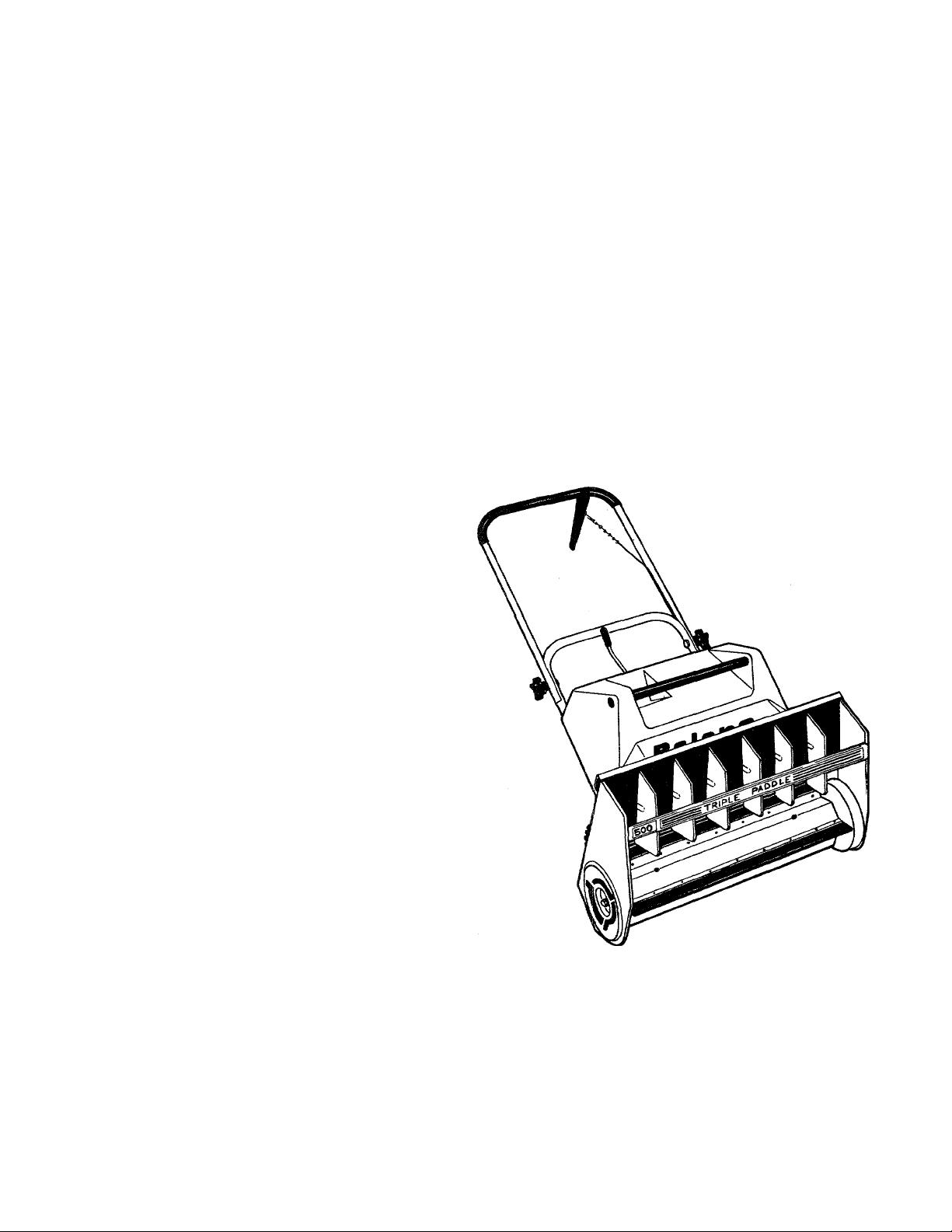
Baiens,
Snow Thrower
Models 225
225E
300
300E
350
350E
500
500E
520
Safety and
Operation
Instructions
FORM 553512-5 (8/85)
SUPERSEDES 553512-4
Page 2
INTRODUCTION
Thank you for purchasing this piece of
Bolens equipment. We feel you now own
one of the finest pieces of equipment
money can buy.
This is a safety, operation and general
maintenance manual which does not at
tempt to cover major repairs. Bolens
equipment has been carefully designed,
engineered and manufactured to give
good performance if properly operated
and maintained. Review this manual to
familiarize yourself with the unit, its
features and its operation.
This equipment is manufactured by Bolens
Corporation, 215 South Park Street, Port
Washington, Wisconsin 53074. (Phone;
414-284-5521). If you should have any
questions or encounter any problems
which you feel only the factory can
solve, write to the above address or
call our Service Department.
Your Warranty Statement is also included
(on back cover) with this manual. Please
read it carefully. Also, be sure to complete
and return the included postpaid owner
registration card. The purpose of this
card is to register each unit and owner at
the factory for safety purposes.
CONTACT YOUR DEALER FOR ANY
REPLACEMENT PARTS OR SERVICE
NEEDED. DO NOT RETURN PARTS
DIRECTLY TO THE FACTORY.
THE FACTORY REQUIRES PRIOR
APPROVAL ON RETURNS, AND
APPROVALS ARE ISSUED ONLY TO
BOLENS DEALERSOR DISTRIBU
TORS.
Bolens Corporation reserves the right to
make changes in specifications shown
herein, add improvements, or discontinue
the manufactured product at any time
TABLE OF CONTENTS
Safety Precautions
Identification Numbers
Specifications
Assembly..........................................................5 Storage..........................................................
Controls
..........................................
...................................
..................................................
.........................................................
without notice or obligation.
The iiiusjrations shown throughout this
manual may not look exactly the same as
your snow thrower. Production line
changes as well as differences in models
may alter their appearance.
Know your snow thrower before you
operate it. Carefully review this manual
and become thoroughly familiar with the
operating procedures and safety pre
cautions.
3 Before Operation
4 Operation........................................................8
5 Care and Maintenance..................................
6
...........................................
6
Page 3
GENERAL SAFETY PRECAUTIONS
This symbol is being used to
attract attention to the safety
precautions that should be obeyed by
A
the operator to help avoid accidents.
A
CAUTION
PREVENTING ACCIDENTS IS YOUR
RESPONSIBILITY. BE SURE YOU
UNDERSTAND AND OBSERVE THESE
SAFETY PRECAUTIONS. NEVER
TAKE CHANCES. REMEMBER, ACCI
DENTS CAN BE PREVENTED.
falling, especially when operating in
reverse.
PREPARATION
1. Thoroughly inspect the area where
the equipment is to be used and remove
all door mats, sleds, boards, wires and
other foreign objects.
2. Do not operate equipment without
wearing adequate winter outer garments.
Wear footwear which will improve foot
ing on slippery surfaces.
3. Handle fuel with care, it is highly
flammable.
a. Use approved fuel container.
b. Never add fuel to a running engine
or hot engine.
c. Fill fuel tank outdoors with
extreme care. Never fill fuel tank
indoors.
d. Replace gasoline cap securely and
wipe up spilled fuel.
4. Use a grounded three wire cord and
plug-in for all units with electric starting
motors.
walks, or roads. Stay alert for hidden
hazards or traffic.
3. After striking a foreign object, stop
the engine (motor), thoroughly inspect
the snow thrower for any damage, and
repair the damage before restarting and
operating the snow thrower.
4. If the unit should start to vibrate
abnormally, stop the engine (motor) and
check immediately for the cause. Vibra
tion is generally a warning of trouble.
5. Stop engine (motor) whenever you
leave the operating position, before
unclogging the coliector/impeller housing
or discharge guide, and when making any
repairs, adjustments or inspections.
6. Take all possible precautions when
leaving the vehicle unattended. Stop the
engine and remove the key.
7. When cleaning, repairing or inspect
ing make certain coliector/impeller, and
all moving parts have stopped. Disconnect
cord on electric motors.
8. Do not run engine indoors, except
when starting engine for transporting
snow thrower in or out of building. Open
outside doors, exhaust fumes are danger
ous.
TRAINING
1. Read the operating and service in
struction manual carefully. Be thoroughly
familiar with the controls and proper use
of the equipment. Know how to stop the
unit and disengage the controls quickly.
2. Never allow children to operate
equipment. Never allow adults to operate
equipment without proper instruction.
3. Keep the area of operation clear of
all persons, especially small children and
pets.
4. Exercise caution to avoid slipping or
5. Never attempt to make any adjust
ments while engine or motor is running
(except where specifically recommended
by manufacturer).
6. Let engine and machine adjust to
outdoor temperatures before starting to
clear snow.
OPERATION
1. Do not put hands or feet near
rotating parts. Keep clear of discharge
opening and collector at all times.
2. Exercise extreme caution when
operating on or crossing gravel drives.
9. Exercise extreme caution when
changing directions on slopes. Do not
attempt to clear steep slopes.
10. Never operate snow thrower without
guards, plates, or other safety protective
devices in place.
11. Never operate snow thrower near
glass enclosures, automobiles, window
wells, drop-offs, etc., without proper
adjustment of snow discharge angle. Keep
children and pets away.
12. The exhaust muffler gives off heat.
Avoid contact with any surface which
may be hot.
Page 4
GENERAL SAFETY PRECAUTIONS (continued)
13. Do not overload machine capacity by
attempting to clear snow at too fast a
rate.
14. Never operate machine at high trans
port speeds on slippery surfaces.
15. Never direct discharge at bystanders
or allow anyone in front of unit.
16. Use only attachments and accessories 2. Check scraper bar mounting bolts at
approved by manufacturer of snow frequent intervals for proper tightness to
thrower. insure smooth operation.
17. Never operate the snow thrower
without good visibility or light. Always
be sure of your footing and keep a firm
hold on the handles and walk, never run.
MAINTENANCE AND STORAGE
1. Check engine mounting bolts, etc.
at frequent intervals for proper tightness
to be sure equipment is in safe working
condition.
IDENTIFICATION NUMBERS
Snow Thrower:
Model Number_
Serial Number_
3. Never store machine with fuel in the
fuel tank inside a building where open
flame or spark are present. Allow engine
to cool before storing in any enclosure.
4. Always refer to owner's guide
instructions for important details if snow
thrower is to be stored for an extended
period.
5. Run machine a few minutes after
throwing snow to prevent freeze up of
collector/impeller.
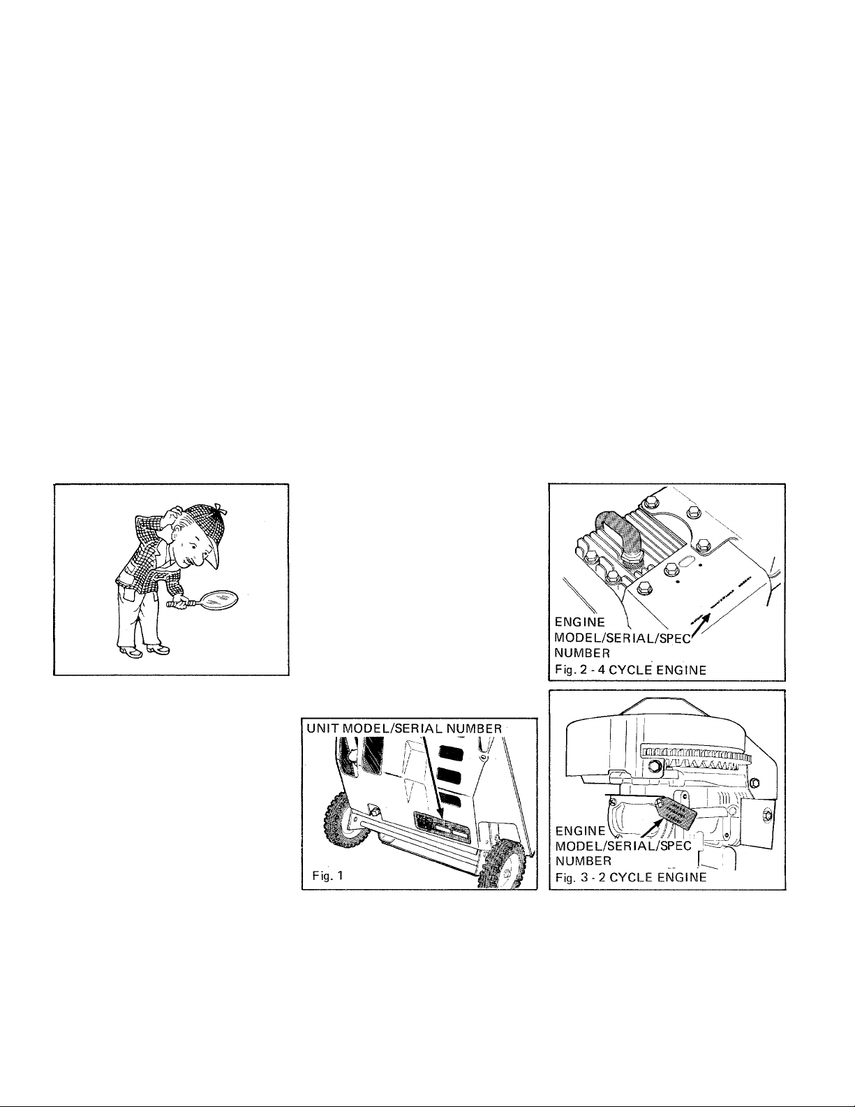
For prompt service when repairs or adjust
ments are required, your AUTHORIZED
BOLENS DEALER must have identifi
cation numbers listed. Fill in the spaces
now for quick reference.
The AUTHORIZED BOLENS DEALER
has a parts list for your snow thrower. He
can identify and supply any parts you
require. Contact the engine manufacturer's
authorized dealer when engine parts are
needed.
Engine:
Model Number.
Serial Number-
Spec. Number_
Date of Purchase:.
Page 5
SPECIFICATIONS
Model
225 225E
Single-Stage Single-Stage
Engine
Fuel Cap 2 qt./1.9 L 2 qt./1.9 L 2 qt./1.9 L
Cutting Width
Auger Triple-Paddle Impeller Hi Capacity Poly V Belt
Wheel Size 1.5 X 6" Rubber
Approx. Weight 42 lbs./19.0 Kg 42 lbs./19.0 Kg 50 lbs./22.7 Kg
Start
Tecumseh
2.25 HP/1.7 kW
2 cycle
20"/51 cm 20"/51 cm
(3.8 X 15.2 cm)
MANUAL
YES MANUAL YES MANUAL YES
Auger Clutch Kit Available Kit Available Yes Yes
Snow Discharge
Fold Down
Yes Yes
300 300E 350
Single-Stage
Tecumseh
3.0 HP/2.2 kW
2 cycle
1.5 X 6" Rubber
(3.8 X 15.2 cm)
3.5 HP/2.6 kW
1.5 X 6" Rubber
(3.8 X 15.2 cm)
3 Way Directional
350E 500
Single-Stage
Tecumseh
4 cycle
20'751 cm
1.5 X 7" Rubber
(3.8 X 17.8 cm)
52 lbs./23.6 Kg
MANUAL YES
Yes Yes
500E
Tecumseh
5 HP/3.7 kW
4 cycle
2 qt./1.9 L
24'V61 cm
520
Single-Stage
Tecumseh
5 HP/3.7 kW
4 cycle
2 qt./1.9 L
20"/51 cm
1.5 X 6" Rubber
(3.8 X 15.2 cm)
50 lbs./22.7 Kg
MANUAL
Yes
Yes
Handles
* MANUAL START UNITS MAY ACCEPT AN ELECTRIC START KIT, CONTACT YOUR AUTHORIZED ENGINE
DEALER.
ASSEMBLY
Remove Snow Thrower from carton and
assemble as described.
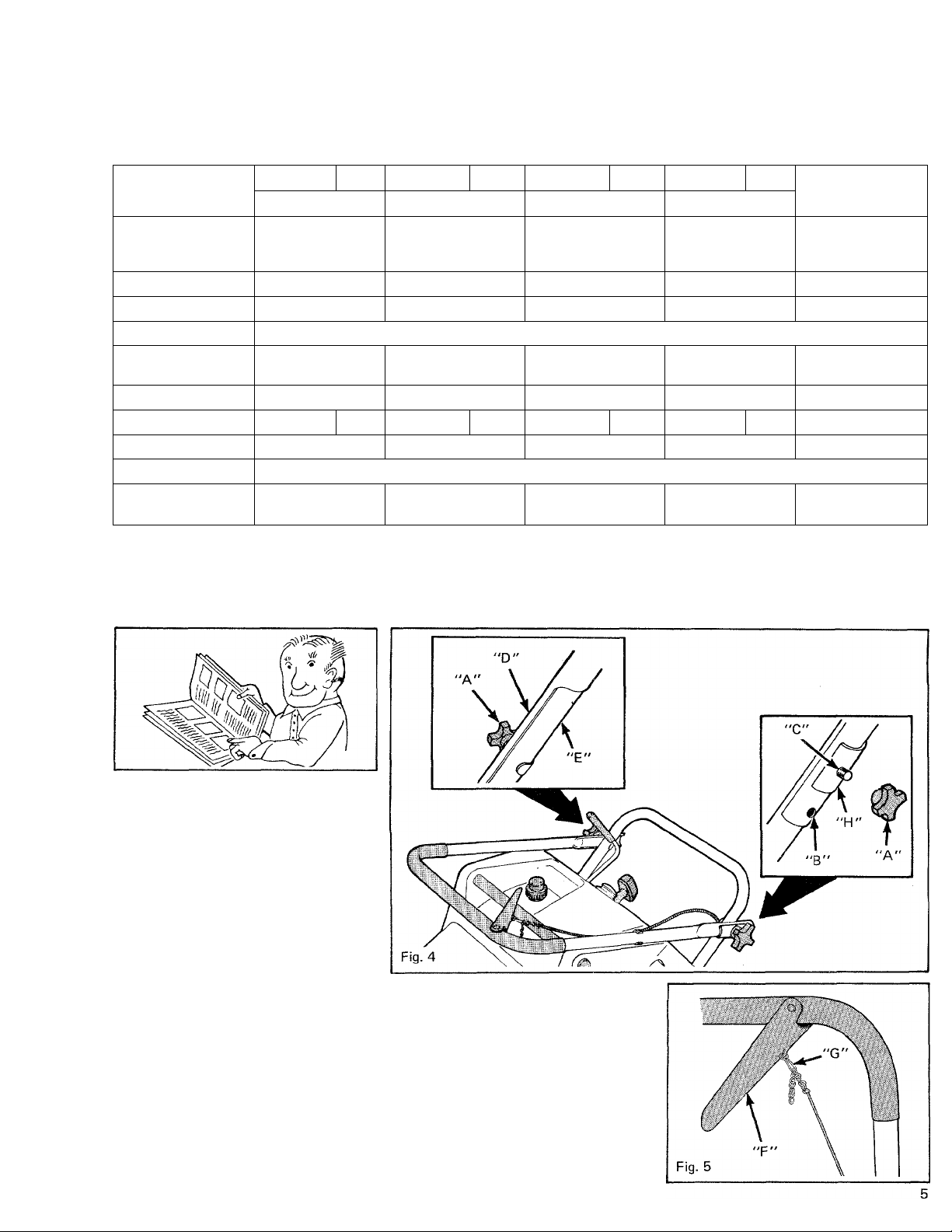
1. HANDLE INSTALLATION
The snow thrower was shipped with the
handle in the folded down position. To
position handle for operation:
a. Remove hand knobs (A), Figure 4.
b. Lift handle up and position in
either of two operating positions:
HIGH position (B) or LOW position
(C). Pinched ends of upper handle (D)
must fit snugly around lower handle
(E).
c. Place handle plates (H) onto
threaded studs.
d. Retighten hand knobs.
e. if snow thrower is equipped with
an auger clutch control, (F) Figure 5,
the following must be done for proper
clutch engagement.
With auger clutch handle down, pull
cable up (to remove slack) until a solid
resistance is felt. Select the chain link
closest to open end of clutch lever hook
(G) and assemble. Release cable.
This procedure should provide proper
clutch engagement.
Page 6
CONTROLS
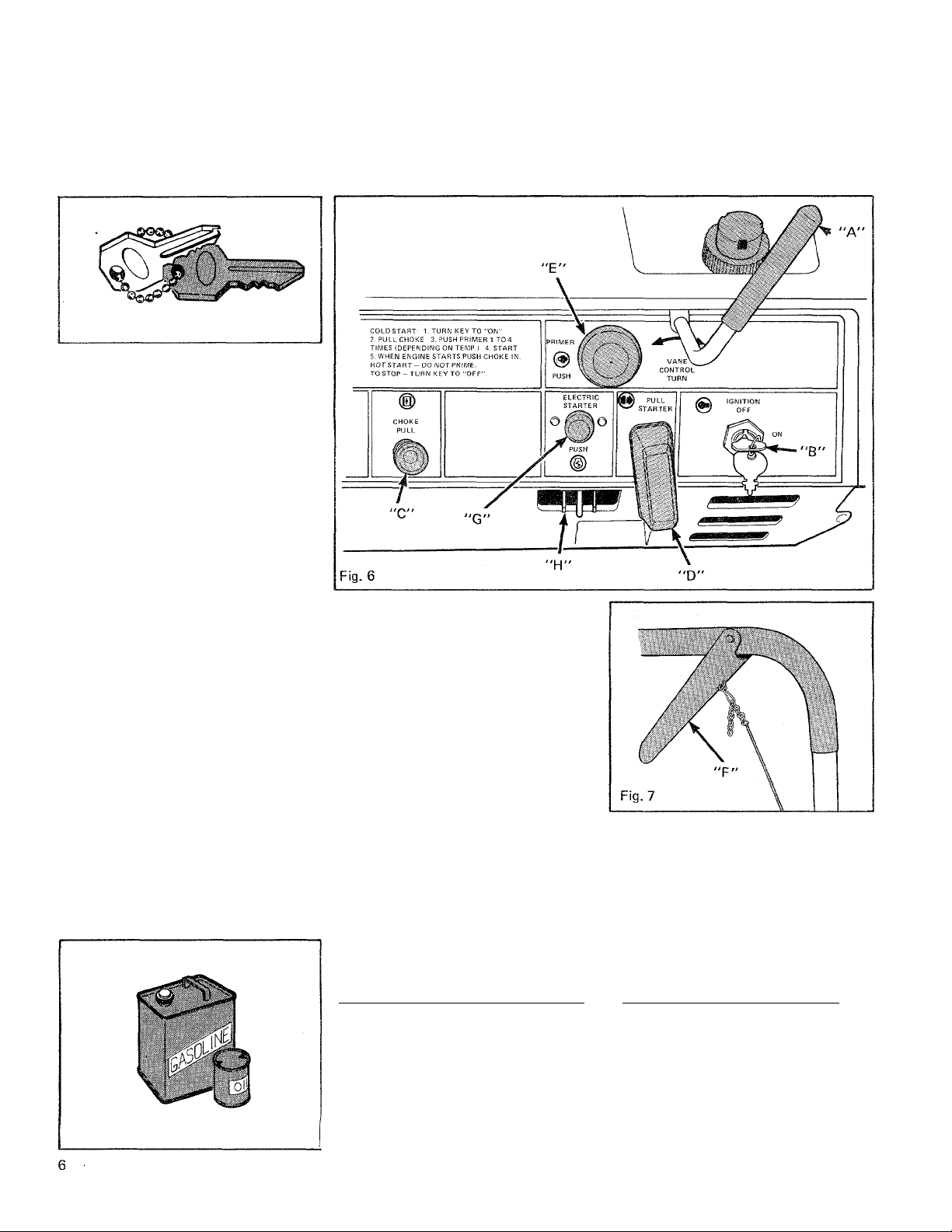
VANE CONTROL
The vane control (A), Figure 6, is used to
directsnowdischarge left, right or straight
ahead.
IGNITION KEY
The ignition key (B), Figure 6, allows the
starting and stopping of engine.
CHOKE CONTROL
The choke control (C), Figure 6, aids in
cold engine starting.
RECOIL STARTER
This starter rope (D), Figure 6, allows the
engine to start (by pulling) with the key
ON.
PRIlVIER BUTTON
The primer button (E), Figure 6, permits
the operator to hand prime (by pressing)
the engine carburetor. NOTE: When
priming (Models 225 & 225E only) be
sure your thumb is covering vent hole.
BEFORE OPERATION
ELECTRIC STARTER BUTTON
(Electric Start Models Only)
This starter button (G), Figure 6, is used
to start the engine (by pressing) with the
ignition key ON.
AUGER CLUTCH (Some Models)
This control (F), Figure 7, engages impel
ler when pulled up to handle bar and dis
engages impeller when released.
A
WARNING
MODELS 350,305E, 500,500E & 520
THIS SNOW THROWER WAS
SHIPPED WITHOUT LUBRICA
TION IN THE CRANKCASE. FILL
THE 4 CYCLE ENGINE, IF SO
EQUIPPED, WITH OIL AS OUT
LINED IN THIS MANUAL AS WELL
AS THE ENGINE MANUAL.
MODELS 225,225E, 300 & 300E
THE 2 CYCLE ENGINE HAS NO
OIL SUMP IN THE CRANKCASE,
THEREFORE RELIES ON THE OIL
IN THE FUEL MIXTURE FOR
LUBRICATION.
Page 7
BEFORE OPERATION (continued)
A
CAUTION
DO NOT REFUEL WHILE ENGINE IS
RUNNING OR HOT. KEEP SMOKERS
AND FLAMES AWAY WHEN REFUEL
ING.
MODELS 225, 225E, 300 & 300E (2 Cycle Engine)
A two cycle engine has no oil sump in the
crankcase; therefore it relies on the oil in
the fuel mixture for lubrication.
A
CAUTION
ALL 2 CYCLE ENGINES MUST HAVE
OIL MIXED INTO THE FUEL.
Mix oil with fresh clean unleaded auto
motive gasoline. (Leaded "regular" grade
gasoline is an acceptable substitute.) See
FUEL MIX CHART. Use SAE 30 or 40
outboard or 2-cycle oil. DO NOT USE
AUTOMOTIVE OILS. Disregard instruc
tions on oil containers. DO NOT mix
directly in engine fuel tank. Doing so
could cause engine damage. Refer to
engine owner's manual.
U.S.
Gas
1 Gal. 4 oz.
2 Gal. 8 oz.
5 Gal. 20 oz.
Oil To
Be Added
2 CYCLE ENGINES
FUEL MIX CHART
Mixture 32:1 (3% mixture)
IMPERIAL
Gas
1 Gal. 4.5 oz. 4 Liters
2 Gal.
5 Gal.
Oil To
Be Added
9 oz.
22 oz.
Petrol
8 Liters .250 L
20 Liters
S.l. (METRIC)
Oil To
Be Added
.125 L
.625 L
FOR THOROUGH MIXING OF OIL
AND GASOLINE- Fill can to one quarter
full, add oil per chart, shake can vigorously,
fill remainder of can with gas and reshake
contents. ONCE MIXED, OIL AND
GASOLINE WILL NOT SEPARATE.
MODELS 350, 350E, 500 500E & 520 (4 Cycle Engines)
Fill tank with fresh, clean unleaded
automotive gasoline. (Leaded "regular"
grade gasoline is an acceptable substi
tute).
A
CAUTION
DO NOT MIX OIL WITH THE GASO
LINE. NEVER USE PREMIUM OR
WHITE GASOLINE. (4 CYCLE
ENGINES). THE USE OF GASOHOL IS
NOT RECOMMENDED.
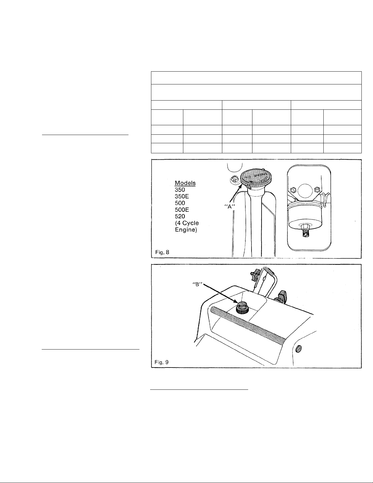
MODELS 350, 350E, 500 500E & 520
FILL ENGINE CRANKCASE - 4 CYCLE
ENGINES ONLY
Before operating, fill the crankcase to
"FULL" mark on dipstick (A), Figure
8, using proper grade and amount of
a quality engine oil.
Page 8
OPERATION
NOTE
When first operating snow thrower give
yourself ample time to acquaint yourself
with the machine. Practice using ALL
controls.
STARTING THE ENGINE (RECOIL
START)
1. Turn ignition switch to "ON"
position.
2. Pull choke.
3. Push primer button 1 to 4 times
(depending on temperature). In tempera
tures above -t-15°F (-10°C) use one or
two primes. In temperatures below
-f15°F (-10°C) use three or four primes.
To prime engine, fully depress primer
bulb with your thumb (if primer bulb has
a vent hole, be sure thumb covers hole
when priming). Release and allow bulb to
return to original position. An engine
should be primed if it is new, cold, stored,
unused for an extended period of time or
has been run dry of fuel.
4. Start engine. Hot or cold start —
pull starter rope (see "STARTING
INSTRUCTIONS" in engine manual).
5. When engine starts, push choke con
trol in (if choking was necessary).
6. Pull up auger clutch control (if so
equipped) to engage impeller. If adjust
ment is necessary refer to CARE AND
MAINTENANCE section.
2. Follow steps 1,2 and 3 from recoil
start engine starting instructions.
3. Press starter button (see "START
ING INSTRUCTIONS" - Electric Start
section in engine manual). Release as
soon as engine starts.
A
CAUTION
DO NOT CRANK WITH ELECTRIC
STARTER FOR MORE THAN 60
SECONDS. IF CRANKED FOR 60
SECONDS STARTER SHOULD NOT BE
OPERATED AGAIN FOR 20 MINUTES
TO ALLOW IT TO COOL.
4. After engine starts, push choke con
trol in (if choking was necessary) and re
move extension cord (from receptacle
first).
5. Pull up auger clutch control (if so
equipped) to engage impeller. If adjust
ment is necessary refer to CARE AND
MAINTENANCE section.
STOPPING THE ENGINE
1. Turn ignition key to "OFF" position.
Remove key.
2. Be sure all moving parts have stopped
before leaving the operator's position.
A
CAUTION
STOP THE ENGINE BEFORE:
• Adding fuel.
• Leaving snow thrower unattended,
if only for a minute.
• Clearing discharge opening.
• Making any repairs or adjustments to
unit.
2. Spray the inside of impeller paddle
housing and directional vanes with Bolens
silicone spray to help prevent snow build
up. A coat of paste wax is also suitable.
3. All covers and guards must be in
place and all nuts, screws and other
fasteners tight.
4. Allow engine to warm up approx
imately five (5) minutes before using.
5. Removing snowfall as soon as possible
produces the best results.
6. To obtain the greatest performance
from snow thrower, place vanes in a
vertical position, discharge snow down
wind and overlap each pass slightly.
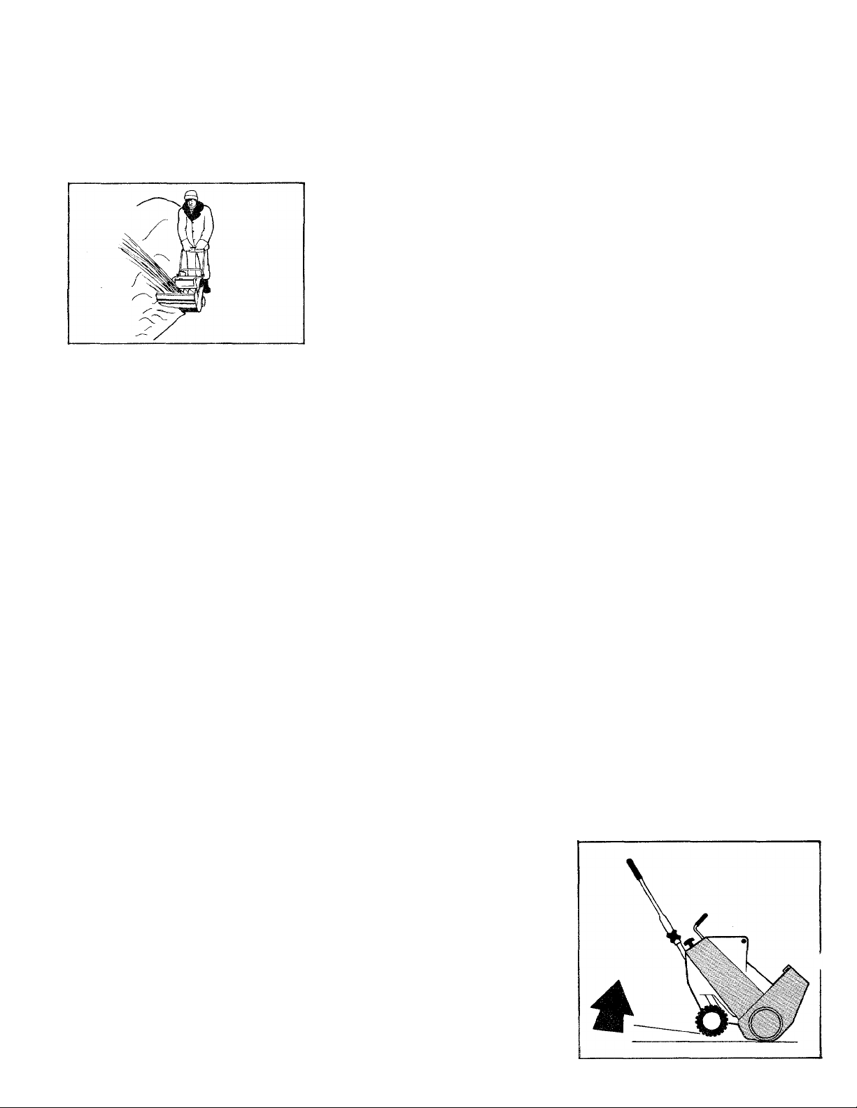
7. The type of snow you are throwing
will dictate to you how to use this
machine. In light, fluffy snow the unit
will propel itself if tilted forward slightly
(lifting up on handle - as shown below)
allowing the impeller paddles to contact
the ground. In heavy wet snow the unit
will propel itself forward without tilting.
NOTE; The depth and weight of snow to
be cleared will control forward speed of
snow thrower.
8. In heavy, wet snow overlapping is
essential to prevent overloading. Permit
machine to work at a slow pace. If engine
slows down due to overloading, pull
unit back out of snow and/or release
auger clutch control (if so equipped)
until engine regains full power. Then
allow machine to propel itself back into
snow.
STARTING THE ENGINE (ELECTRIC
START)
1. Plug cord into starter switch con
nector (H), Figure 6, and a convenient
120 volt outlet.
OPERATING TIPS
1. Before the first snowfall thoroughly
inspect area where snow removal will
take place. Remove all door mats, sleds,
boards, wires, etc. that might be picked
up and thrown by tbe impeller paddles.
Page 9
OPERATION (continued)
9. To clear snow from steps or to cut
down drifts, hold snow thrower by the
upper and lower handles and use a sideto-side (swinging) motion.
10. Before storing unit, let engine run
a few minutes to keep ice from forming
on moving parts. Clear control panel of
snow and/or water to eliminate possible
freeze up of controls.
11. When storing unit, move vanes to
vertical position to prevent possible dis
tortion of vanes.
TROUBLESHOOTING
Before you take your snow thrower in
for repairs, make sure you have followed
the instructions in this manual. Check to
see if the malfunction is something you
can correct yourself. The above table may
help you locate your problem.
PROBLEM
1. Engine will turn over
but will not start
2. Starts only after
repeated tries
3. Idles rough
4. Engine overheats
5. Impeller does not turn
6. Electric start unit
will not crank the
engine
7. Snow Thrower will
not throw snow
8. Engine will not
stop with key off.
CAUSE
1. Ignition switch in “OFF" position.
2. Faulty or fouled spark plug.
3. Spark plug wire disconnected.
4. Empty fuel tank.
5. Incorrect choke setting.
1. Faulty or fouled spark plug.
2. Incorrect choke setting.
1. Faulty or fouled spark plug.
2. Incorrect choke setting.
1. Dirty air screen (4 cycle engines).
2. Low oil level (4 cycle engines).
3. Spark plug loose.
4. Dirty cooling fins.
5. Improper fuel mix (2 cycle engines).
1. Torn or worn belt.
2. Auger Clutch not engaged.
1. Extension cord not plugged in.
2. Fuse or circuit breaker for outlet blown.
3. Faulty extension cord or plug.
1. Auger Clutch not engaged.
2. Worn impeller paddles.
3. Worn or torn drive belt.
1. Faulty or disconnected ignition switch.
2. Lead wire broken.
CARE AND MAINTENANCE
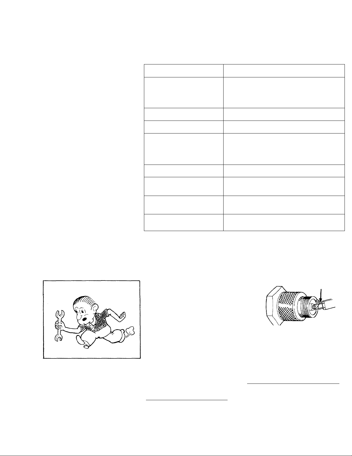
SPARK PLUG
Clean and regap spark plug as
necessary, Figure 10. 2 CYCLE
ENGINE: .035" (0.9mm) - 4 CYCLE
ENGINE: .030" (0.76mm). Refer to
Engine Manual for cleaning proce
dure and replacement. When
removing plug for maintenance be
sure to clean area around spark
plug to prevent dirt from entering
engine. The spark plug is located
under the upper cover.
A dirty, oily or carboned spark plug
makes starting difficult and causes
Check and tighten (if necessary) all
nuts and bolts before using this
machine and periodically thereafter
(approx, every two (2) hours of
operation). Vibration and/or rough
handling may cause hardware to
loosen. Tighten as required.
Refer to Engine Manual for mainte
nance procedures and requirements
not covered in this manual.
inefficient operation.
ENGINE CRANKCASE
MODELS 225, 225E, 300 & 300E
2 CYCLE ENGINE - Proper engine
lubrication is provided by adding
the correct pre-mixed fuel to
gasoline tank. See page 7.
FEELER GAUGE
COMPLIANCE WITH RADIO INTER
FERENCE REGULATIONS CER
TIFIED. REPLACE SPARK PLUG
WITH RESISTOR SPARK PLUG
ONLY.
Fig. 10
MODELS 350,350E, 500, 500E & 520
4 CYCLE ENGINE - Change oil
after first 2 hours of operation and
every 25 hours thereafter. Check oil
level every 5 operating hours. Posi
tion snow thrower in its normal
Page 10
CARE AND MAINTENANCE
operating position (wheels and
scraper blade on the ground). Clean
dirt and/or snow from around open
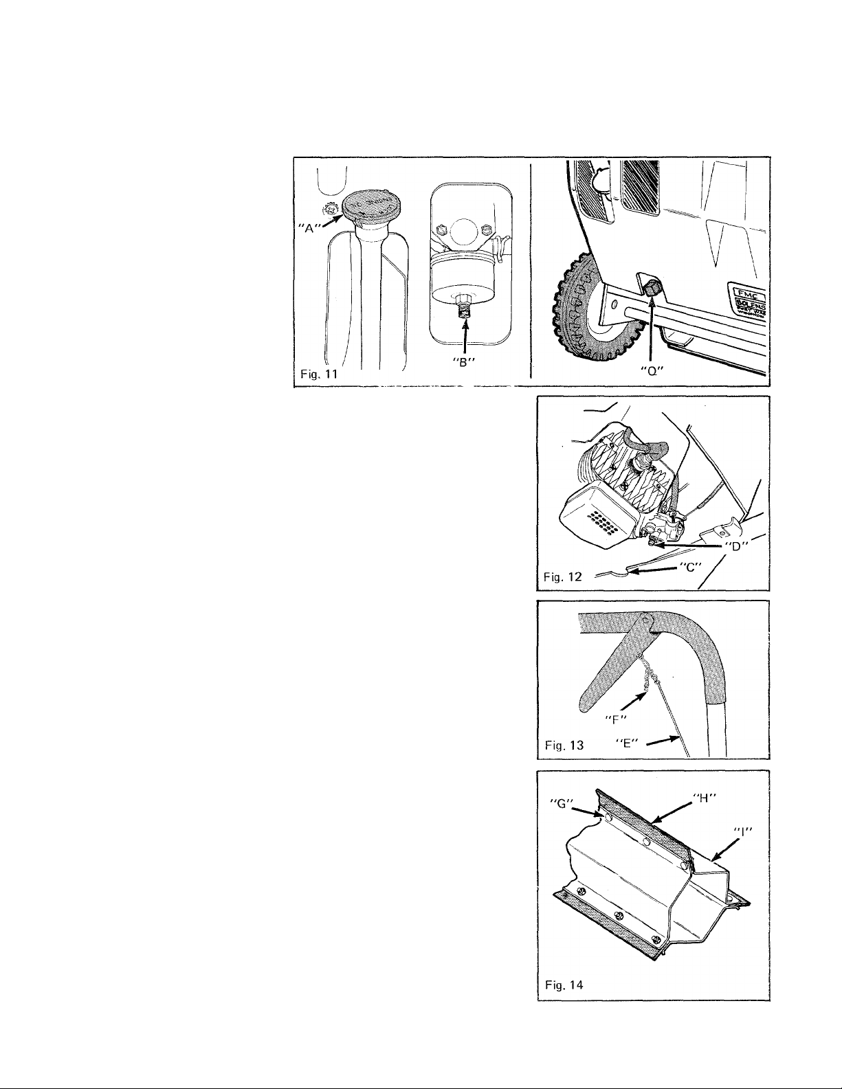
ing (A), Figure 11. Keep oil level to
"FULL" mark on dipstick. Refer to
Engine Manual for proper proce
dure to drain and refill engine
crankcase. The drain plug (Q), Fig
ure 11 is located on backside of unit
in the bottom left-hand corner.
Refer to Engine Manual and/or
BEFORE OPERATION instructions
for proper type oil and quantity.
CARBURETOR ADJUSTMENTS
DO NOT MAKE UNNECESSARY
ADJUSTMENTS. FACTORY SET
TINGS ARE SATISFACTORY FOR
MOST APPLICATIONS AND CON
DITIONS. HOWEVER IF ADJUST
MENTS ARE NEEDED, PROCEED
AS FOLLOWS.
4 CYCLE ENGINE - The engine has
been pre-set to run at 3600 RPM.
Turn high speed adjustment needle
(B), Figure 11, to regulate flow of
gasoline to the engine. For com
plete adjustment procedure, refer to
Engine Manual.
IMPORTANT
When closing adjusting needles,
close finger tight only. Forcing may
cause damage.
2 CYCLE ENGINE - The engine has
been pre-set to run at 4300 RPM.
Through opening (C), Figure 12, in
hand side of machine, turn the
mixture adjusting screw (D) (using
a screwdriver) to regulate flow of
fue l to the engine.
IMPORTANT
Do not force screw tight. Damage to
carburetor or screw could occur.
Refer to Engine Manual for com
plete adjustment procédure.
IMPELLER CLUTCH ADJUSTMENT
(for models so equipped)
Adjust cable (E), Figure 13 up or
down by moving chain (F) one-half
line (one loop) at a time. If impeller
doesn’t rotate when engaged,
unhook chain, pull up on cable and
rehook chain in next lower loop. If
impeller rotates without engaging,
unhook chain and rehook chain in
10
next highest loop. Repeat proce
dure until proper adjustment is
achieved.
PADDLE REPLACEMENT
If paddles become worn and fail to
propel the snow thrower, replace
ment may be necessary. Replace all
3 paddles, one at a time. STOP
ENGINE.
1. Remove screws (G), Figure 14,
that secure paddle (H) to Impeller
frame (I).
2. Remove old paddle.
3. Install new paddle and secure it
to impeller using the same screws
and hex nuts used to secure old
paddle.
4. Repeat procedure for other
paddles.
BELT ADJUSTMENT - MODELS
225, 225E, 300 & 300E
If the Idler pulley does not apply
enough tension to belt to drive
impeller, adjust belt as follows:
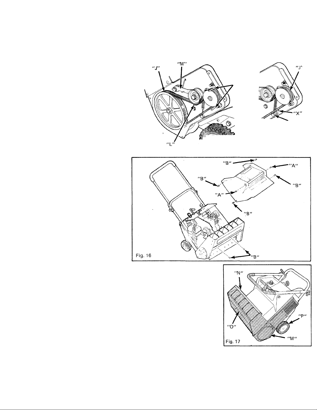
1. Remove drive cover. Remove
the (8) screws (A & B) shown in
Figure 16. Two plugs, in cover, must
be removed to reach screws (A).
2. Remove anchor screw (Q), Fig
ure 15, and reinstall screw in low
position shown in Figure 15.
NOTE
Spring must never be stretched
(measured from end to end) more
that 3" (76 mm), if necessary, repo
sition anchor screw to position "X",
Figure 15.
3. Reinstall drive cover.
Page 11
CARE AND MAINTENANCE (continued)
BELT REPLACEMENT
If belt becomes badly worn or
breaks, replace belt as follows:
STOP ENGINE.
1. Remove drive cover. Remove
the (8) screws (A & B) shown in
Figure 16. Two plugs, in cover, must
be removed to reach screws (A).
2. Remove anchor screw (Q), Fig
ure 15, (Models 225, 225E, 300 and
300E).
3. Loosen belt fingers (K) and belt
guide (L), (Models 350, 350E, 500
and 500E).
4. Remove old belt (J).
5. Install new belt.
6. With spring hooked around
anchor screw shaft (Models 225,
225E, 300 & 300E) reinstall anchor
screw in position "X", Figure 15.
Check belt tension. The idler pulley
must apply enough tension to drive
impeller. If it doesn’t, refer to "BELT
ADJUSTMENT" (Models 225, 225E,
300 & 300E).
7. Repostion and tighten belt fin
gers and guide (Models 350, 350E,
500 & 500E).
8. Reinstall drive cover.
(MODEL 350
500 & 520)
Fig. 15
"K"
"Q"
MODEL 225 & 300
\\"\a, ■
MAINTENANCE SCHEDULE
BEFORE EACH USE;
.1 Check crankcase oil level - 4
cycle engines only.
2. Check for loose screws and
nuts - especially engine hardware.
Retighten if needed.
AFTER EACH USE:
1. Clean machine of all snow and
slush. Brush out housing to remove
sand and gravel.
DURING EACH SEASON; as
needed, lubricate in the areas
indicated in Figures 15 and 16 using
a lightweight motor oil.
1. Idler Arm (M) (under drive
cover). Figure 15 or 17.
2. Vane Control Mechanism (N)
(under upper cover).
3. Impeller Bearings (O) (on both
ends of impeller).
4. Wheels (P).
AFTER EACH SEASON:
1. Check for belt wear.
2. Perform "STORAGE"
instructions. (Engine and Owner
Manuals)
3. Wipe oil or grease on all bare
metal surfaces.
STORAGE
Remove snow and ice from unit.
Perform the STORAGE instructions
outlined in the Engine Manual.
Touch up areas where paint has
chipped off. Coat areas which do
not get painted with oil or grease to
prevent rust.
Refer to the "CARE AND
MAINTENANCE” section and
perform all greasing and oiling as
required.
Store unit in a dry area. Fold down
handles as shown in Figure 17 and
cover unit for additional protection.
11
Page 12

LIMITED WARRANTY
All new Bolens equipment is warranted by Bolens Corporation, to the original retail purchaser only, to be free from defects in material and
workmanship under normal use and service for a period of one year from date of purchase. (This period is limifed fo 90 days if product is
purchased for commercial, institutional, industrial, rental or demonstrator use.) This 90 day limitation does not apply to Bolens QT, HT and
Diesel Model tractors and their attachments manufactured at Bolens. This warranty does not apply to engines manufactured by Briggs and
Stratton, Tecumseh, Kohler and Wisconsin or transmissions manufactured by Peerless. Warranties with respect to these components are
provided by their respective manufacturers and copies of such warranties are-delivered with each new Bolens product.
Bolens Corporation’s obligation under this warranty is limited to the repair or replacement, at its option by an authorized Bolens equipment
dealer, of any part found to be defective in material or workmanship without charge for parts and labor.
In order to obtain warranty service, the owner is responsible for:
1) Providing proof of purchase documentation, ownership registration or copy of bill of sale.
2) Informing any authorized Bolens equipment dealer of the defect and making the product available for repair. (Charges for pick-up,
delivery and service calls are not covered by this warranty.)
This warranty does not cover defects, malfunctions or failures caused by;
1) Use of unauthorized accessories or attachments.
2) Lack of reasonable and necessary maintenance as specified in fhe “Operation and Safety Instructions”.
DISCLAIMER OF CONSEQUENTIAL DAMAGES; BOLENS CORPORATION SHALL NOT BE LIABLE UNDER ANY CIRCUMSTANCES FOR
ANY INCIDENTAL OR CONSEQUENTIAL DAMAGES OR EXPENSE OF ANY KIND, INCLUDING BUT NOT LIMITED TO COST OF EQUIP
MENT RENTAL, LOSS OF PROFITS OR COST OF HIRING SERVICES TO PERFORM TASKS NORMALLY PERFORMED BY THE
EQUIPMENT.
LIMITATION OF IMPLIED WARRANTIES: ANY IMPLIED WARRANTIES, INCLUDED WITHOUT LIMITATION ANY IMPLIED WARRANTY
OF MERCHANTABILITY OR FITNESS FOR A PARTICULAR PURPOSE, SHALL BE LIMITED IN DURATION TO A PERIOD OF ONE YEAR
(90 DAYS IF PRODUCT IS PURCHASED FOR COMMERCIAL, INSTITUTIONAL, INDUSTRIAL, RENTAL OR DEMONSTRATOR USE) FROM
THE DATE OF SALE,
SOME STATES DO NOT ALLOW THE EXCLUSION OR LIMITION OF INCIDENTAL OR CONSEQUENTIAL DAMAGES, OR LIMITATIONS
ON HOW LONG AN IMPLIED WARRANTY LASTS, SO THE ABOVE LIMITATION OR EXCLUSION MAY NOT APPLY TO YOU.
This warranty gives you specific legal rights, and you may also have other rights which vary from state to state.
Bolens Corporation
215 South Park Street
Port Washington, Wisconsin 53074 3107-6
 Loading...