

Page 1

OWNERS
MANUAL
.75
ASSEMBLY
OPERATION
MAINTENANCE
PARTS LIST
5 and 8 H.P.
LOG SPLITTERS
Model Numbers
244-642-000
244-645-000
24642L
24645L
Important:
Read Safety Rules and
Instructions Carefully
PRINTED IN U.S.A.
Thank you for purchasing an
American buiit product.
FORM NO. 770-3092
(R830628)
Page 2

INDEX
Operation Practices........................................................ 3
Assembly Instructions .................................................... 5
Operation........................................................................ 8
Maintenance
.................................................................
10
r
limite;d warranty
♦
♦
♦
♦
♦
♦
♦
♦
For one year from the date of original retail purchase, MTD PRODUCTS INC will either
repair or replace, at its option, free of charge, F.O.B. factory or authorized service firm, any
part or parts found to be defective n material or workmanship. Transportation charges for
the movement of any power equipn ent unit or attachment are the responsibility of the pur
chaser. Transportation charges for any parts submitted for replacement under this warran
ty must be paid by the purchaser ur less such return is requested by MTD PRODUCTS INC.
This warranty will not apply to any part which has become inoperative due to misuse, ex
cessive use, accident, neglect, improper maintenance, alterations, or unless the unit has
been operated and maintained in accordance with the instructions furnished. This warran
ty does not apply to the engine, mo or, battery, battery chargeror component parts thereof.
Please refer to the applicable man jfacturer’s warranty on these items.
Off-Season Storage .....................................................11
Illustrated Parts......................................................12, 14
Repair Parts List....................................................13, 14
Parts Information...........................................Back Cover
♦
♦
♦
♦
♦
♦
♦
t
♦
♦
♦
t
This warranty will not apply where the unit has been used commercially.
Warranty service is available throuqh your local authorized service dealer or distributor. If
you do not know the dealer or distri Dutor in your area, please write to the Customer Service
Department of MTD.
The return of a complete unit will r ot be accepted by the factory unless prior written per
mission has been extended by MTD.
This warranty gives you specific kgal rights. You may also have other rights which vary
from state to state.
1.
WARNING I
®c
■'0 PURCHASERS
OF INTERNAL COMBUSTION ENGINE EQUIPPED
MACHINERY OR DEVICES IN THE STATE OF CALIFORNIA
The equipment which you have just purcha; ed does not have a spark arrester. If this equipment is used on
any forest covered land, brush covered land, or grass covered unimproved land in the State of California,
before using on such land, the California la\i/ requires that a spark arrester be provided, in addition, spark
arrester is required by law to be in effec ive working order. The spark arrester must be attached to the
exhaust system and comply with Section 44<^ 2 of the California Public Resources Code.
♦
♦
♦
♦
♦
♦
Page 3

IMPORTANT
It is suggested that this manual be read in its entirety before attempting to assemble or operate. Keep this manual
^in a safe place for future reference and for ordering replacement parts.
This unit is shipped WITHOUT GASOLINE or 01L. After assembly, see separate engine manual for proper fuel and
engine oil recommendations.
Your log splitter is a precision piece of power equipment, not a plaything. Therefore exercise extreme caution at
all times.
SAFE OPERATION PRACTICES FOR LOG SPLITTERS
TRAINING
1. Know the controls and how to stop quicklyREAD THIS OWNER'S MANUAL.
2. Do not allow children to operate. Do not allow
adults to operate it without proper instruction.
Only persons well acquainted with these rules of
safe operation should be allowed to use your log
splitter.
3. Never use your splitter for any other purpose
than splitting wood. It is designed for this use
only and any other use may cause an injury.
4. Only the operator is to be near your log splitter
during use. Keep all others, including pets, a
minimum of 20 feet away from your work zone.
Flying wood can be hazardous.
Don't step over your splitter when engine is
running. You may trip or accidentally activate
ram if you step over. If you need to get to the
other side, walk around.
PREPARATION
Do not wear loose fitting clothing that could get
1
.
caught on the moving parts.
Do not operate equipment when barefoot or
2.
wearing open sandals. Always wear safety shoes or
heavy boots. A dropped log can seriously injure
your foot.
Check the fuel before starting the engine. Do not
3.
fill the gasoline tank indoors, when the engine is
running, or while the engine is still hot. Wipe off
any spilled gasoline before starting the engine.
Use only in daylight or in good artificial light.
4.
Never operate your splitter on slippery, wet,
5.
muddy, or icy surfaces. Safe footing is essential in
preventing accidents. Never operate your splitter
while attached to a towing vehicle.
Always wear safety glasses or goggles while oper
6.
ating your log splitter. A piece of splitting log
could fly off and hit your eyes.
Both ends of each log must be cut square. This
7.
will prevent the log from flying out of the splitter
while under pressure.
OPERATION
1. Do not change the engine governor settings or
overspeed the engine. Excessive engine speeds are
dangerous.
2. Never place hands or feet between log and split
ting wedge or between log and ram during forward
or reverse stroke. To do so may result in crushed
or amputated fingers or toes, or worse, you may
lose an arm or foot.
3. If the equipment should start to vibrate abnor
mally, stop the engine and check immediately for
the cause. Vibration is generally a warning of
trouble.
4. When cleaning, repairing or inspecting, make
certain all moving parts have stopped. Disconnect
the spark plug wire, and keep the wire away from
the plug to prevent accidental starting.
5. Handle gasoline with care. It is highly flammable.
A. Use approved gasoline container.
B. Never remove cap or add gasoline to a running
or hot engine or fill fuel tank indoors. Wipe
up spilled gasoline.
C. Don't run engine in an enclosed area. Ex
haust gases contain carbon monoxide. This
odorless gas can be deadly when inhaled.
6. Always operate the log splitter from the engine
side of the beam.
Stand behind the ram when operating. See drawings.
7. Be careful not to touch the muffler after the
engine has been running. It is HOT.
8. Never try to split two logs on top of each other.
One may fly out and injure you.
Page 4

9. Never attempt to split wood across the grain.
Some types of wood may burst or fly oit of
your splitter and result in injury to you or a
bystander.
10. Never leave your log splitter unattended wit i the
engine running. Shut off the engine if yoi are
leaving your splitter, even for a short period of
of time. Someone could accidentally activati the
ram and be injured.
11. Only use your hand to operate the ram or co itrol
lever. Never use your foot or a rope or any c ther
extension device. This could result in your irabil
ity to stop your splitter quickly enough and
cause an injury.
12. Only operate your splitter on the level ground and
not on the side of a hill. It could tip, or ro ling
logs or poor footing could cause an accicent.
This also prevents the spillage of gas from the
tank.
MAINTENANCE and STORAGE
1. Don't operate your splitter in poor mech; nical
condition or when in need of repair.
2. Keep all nuts, bolts, screws, hose clamp: and
hydraulic fittings tight to be sure equipment is
in safe working condition.
3. Replace all damaged or worn parts such as hy
draulic hoses and fittings immediately with man
ufacturer approved replacement parts.
4.
Never store the equipment with gasoline in the
tank inside of a building where fumes may reach
an open flame or spark. Allow the engine to cool
before storing in any enclosure.
To reduce fire hazard keep engine free of grass,
5.
leaves, wood chips, excessive grease and oil.
The hydraulic system of your log splitter re
6.
quires the careful inspection along with the
mechanical parts. Be sure to replace frayed,
kinked, cracked or otherwise damaged hydraulic
components.
Fluid escaping from a very small hole can almost
7.
be invisible. Do not check for leaks with your
hand. Escaping fluid under pressure can have
sufficient force to penetrate skin, causing serious
personal injury. Leaks can be located by passing
a piece of cardboard or wood over the suspected
leak and look for discoloration.
Should it become necessary to loosen or remove
8.
any hydraulic fitting or line, be sure to relieve
all pressure by shutting off the engine and moving
the control handle back and forth several times.
Don't remove the cap from the hydraulic tank or
9.
reservoir while your log splitter is running. Hot
oil under pressure could cause injury.
10. Never store outside without a waterproof cover.
Rain will cause rust on the inside of the cylinder.
CAUTION
THIS UNIT SHOULD NOT BE TOWED ON ANY
STREET, HIGHWAY OR PUBLIC ROAD. ANY
LICENSING NE EDED TO COMPLY WITH THE
EXISTING FECERAL, LOCAL OR STATE VEH
ICLE REQUIREMENTS IS THE SOLE RESPONSI
BILITY OF THE PURCHASER.
Page 5
ASSEMBLY INSTRUCTIONS
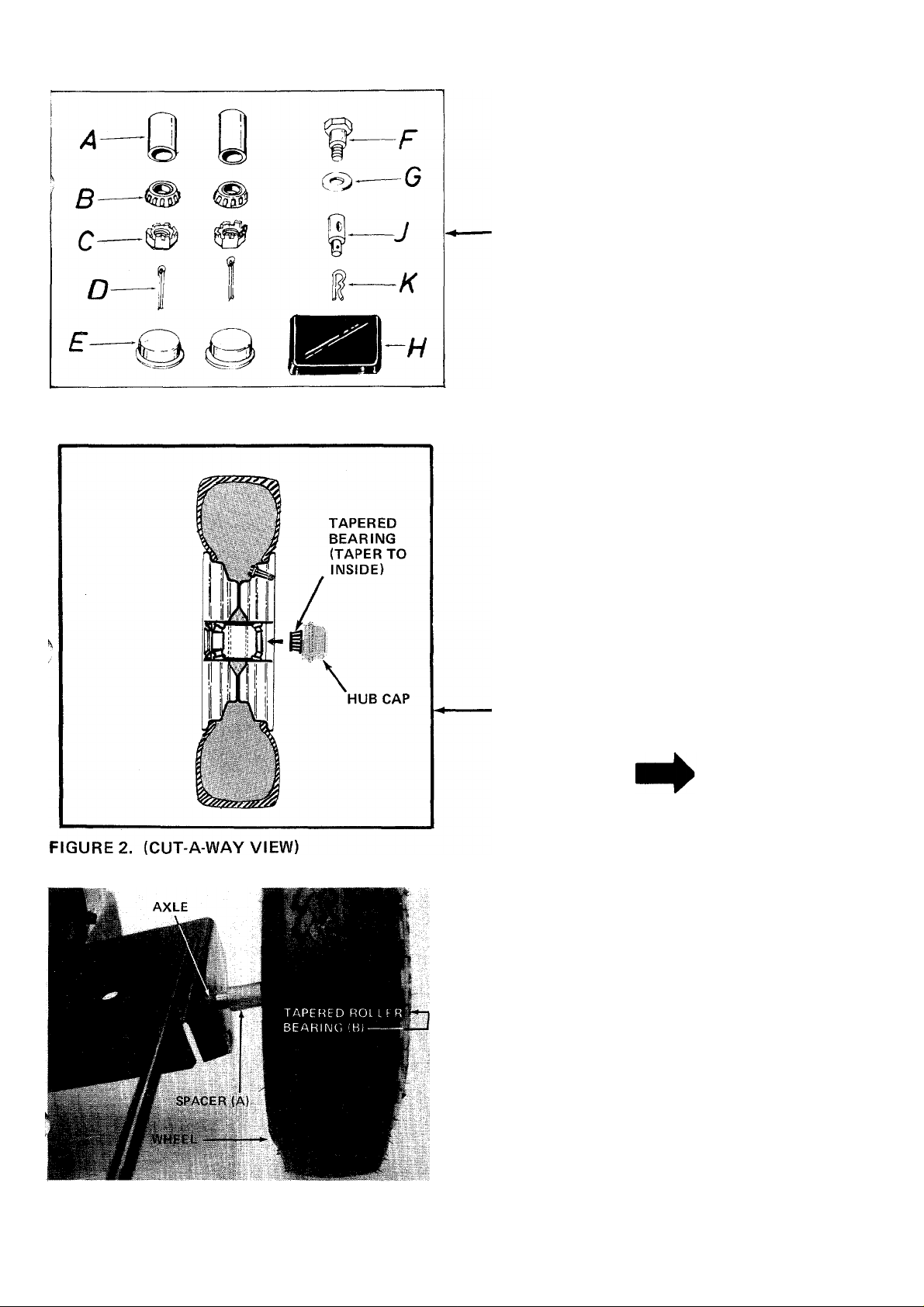
CONTENTS OF HARDWARE PACK (See Figure 1):
(A) (2) Spacers
(B) (2) Tapered Roller Bearings
(C) (2) Hex Castle Nuts 3/4-16 Thread
(D) (2) Cotter Pins
(E) (2) Hubcaps
(F) (1) Shoulder Bolt
(G) (1) Flat Washer
(H) (1) Automotive Grease
(I) (1) Tow Hitch and Stand (Not Shown - See
Figure?)
(J) (1) Ferrule
(K) (1) Hairpin Cotter
FIGURE 1.
TOOLS REQUIRED:
(1) Raw H ide or Plastic Hammer
1-1/8" Wrench or Adjustable Wrench
(1)
3/4" Wrench
(1)
Pipe Wrench
(1)
OTHER MATERIALS NEEDED:
(A) One gallon of regular grade gasoline (for engine)
1-1/2 pints of SAE 30or 10W-30oil (for engine)
(B)
Approximately 2-1/2 gallons of Dexron II auto
(C)
matic transmission fluid. (May be obtained at
your local service station or auto parts store.)
Funnel
(E)
Pipe Sealant
(F)
1. Pack the tapered roller bearings with automotive
grease.
•NOTE
Do not put any grease in the hub caps.
FIGURE 3.
, 2. Place one spacer (A) on axle, then one wheel and
tapered roller bearing (B). See figures 2 and 3.
Page 6
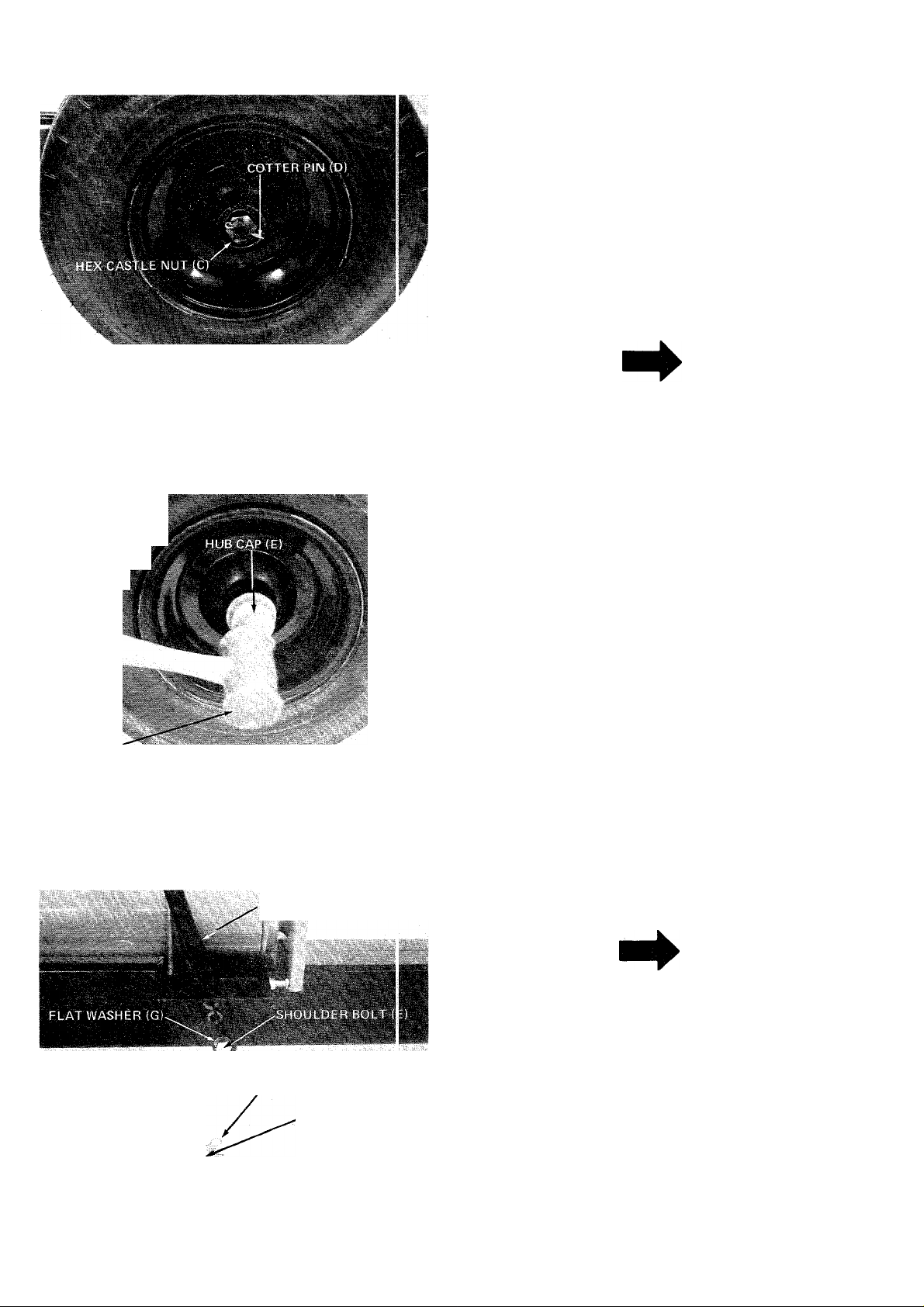
3. Thread hex castle nut (C) on axle. Tighten castle
nut until snug, then back off approximately 1/3
turn or until one of the slots on the castle nut lines
up with hole in axle. Secure castle nut to axle
with cotter pin (D). See figure 4.
NOTE
FIGURE 4.
5. >
H.AMWER
FIGURE 5.
ENGAGEMENT HAND .E
Make certain wheel bearings were
packed with grease before assembly.
4. Place hub cap (E) in position on wheel and tap on
with a plastic hammer. See figure 5.
5. Repeat steps 1 through 4 for the second wheel.
6. Secure engagement handle to beam with shoulder
bolt (F) and flat washer (G). See figure 6.
7. Thread ferrule onto engagement rod until ferrule
lines up with hole in engagement handle, with the
engagement handle placed in neutral position.
Refer to figure 10.
8. Secure engagement rod to engagement handle
with hair pin cotter (K). See figure 6.
ENGAGEMENT ROD
FIGURE 6.
HAIR PIN COTTER
FERRULE (J)
NOTE
For proper adjustment of stroke re
turn stop plunger, refer to page 10.
TIRE PRESSURE
FOR SHIPPING PURPOSES, THE TIRES ON YOUR
UNIT MAY BE OVER-INFLATED. TIRE PRESSURE
SHOULD BE REDUCED BEFORE UNIT IS PUT
INTO OPERATION. RECOMMENDED PRESSURE
SHOULD BE APPROXIMATELY 15 P.S.I. EQUAL
TIRE PRESSURE SHOULD BE MAINTAINED ON
ALL TIRES. MAXIMUM TIRE PRESSURE IS 30
P.S.I.
Page 7
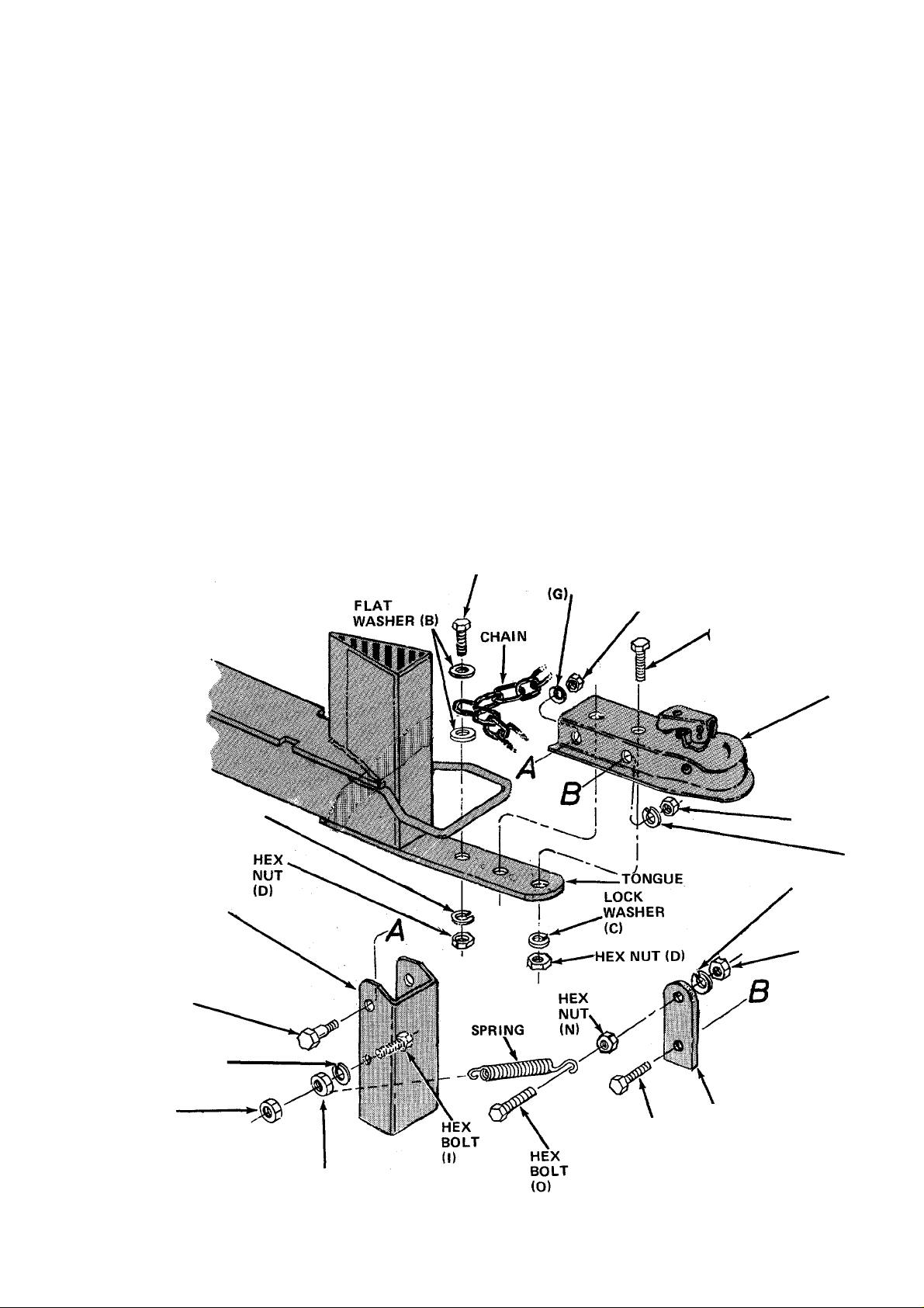
TOW HITCH AND
STAND ASSEMBLY
Hardware for Assembly of Tow Hitch and Stand
A (1) Hex Bolt 3/8-24 x 1-3/4" Long
B (2) Flat Washers 3/8" I.D.
C (3) Lock Washers 3/8" I.D.
D (3) Hex Nuts 3/8-24 Thread
E (2) Hex Bolts 3/8-24 X 1-1/4" Long
F (2) Shoulder Bolts
G (3) Lock Washers 1/4" I.D.
H (2) Hex Nuts 1/4-20 Thread
I (1) Hex Bolt 1/4-28 X 1" Long
J (1) Hex Nut 1/4-28 Thread
K (1) Hex Lock Nut 1/4-28 Thread
L (1) Hex Bolt 5/16-18x3/4" Long
M (2) Lock Washers 5/16" I.D.
N (3) Hex Nuts 5/16-18 Thread
0 (1) Hex Bolt 5/16-18 X 1-1/2" Long
1. Find the center of the tow hitch chain. Place hex
2. Secure tow hitch to tongue of log splitter with
two hex bolts (E>, lock washers (C) and hex nuts
(D). See figure 7.
3. Secure flip stand to hole in the side of tow hitch
nearest the wedge with two shoulder bolts (F),
lock washers (G) and hex nuts (H) as shown in
figure 7.
4. Place hex bolt (I) through the hole in the side of
flip stand as shown in figure 7. Secure with lock
washer (G) and hex nut (J). Thread hex lock nut
(K) on the end of the hex bolt until the end of
the bolt is flush with the hex nut. The spring will
be attached to this bolt in step 7.
5. Attach spring mounting bracket to the tow hitch
with hex bolt (L), lock washer (M) and hex nut
(N). The rounded end of spring mounting bracket
must be assembled to the top as shown in figure
7.
6. Thread hex nut (N) onto hex bolt (0) as far as it
will go. Place hex bolt (0) through the upper hole
in spring mounting bracket with the head of the
bolt to the outside of the unit. Secure with lock
washer (M) and another hex nut (N).
7. Hook spring to hex bolt (0) and between the hex
nuts on hex bolt (I). See figure 7.
LOCK WASHER (C)
FLIP STAND
SHOULDER
BOLT(F)
HEX BOLT (A) LOCK
WASHER
HEX
BOLT
E)
TOW
HITCH
HEX
NUT (N)
^ (M)
LOCK
WASHER
(M)
HEX
NUT
<N)
LOCK
WASHER
LOCK
WASHER (G)
HEX
LOCK
NUT (K)
HEX NUT (J)
HEX
BOLT
(L)
SPRING
MOUNTING
BRACKET
Page 8
OPERATION
BEFORE STARTING
NOTE
Refer to engine manual packed with
log splitter for complete instructions
for the care and maintenance of engine.
READ DIRECTIONS CAREFULLY.
Fill sump with oil as instructed in the sepa ate
1
.
engine manual.
2. Fill fuel tank, using clean, fresh, regular grade
automotive gasoline. Fill tank completely.
Fill reservoir tank on log splitter with the unit
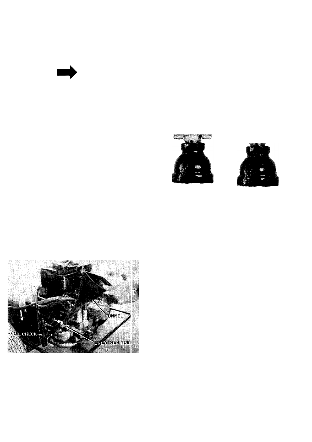
3.
resting on the beam. Remove the breather plug
from breather tube. Remove the plug from the
oil check hole. See figure 8. Pour approximately
2-1/2 to 3 gallons of Dexron automatic tninsmission fluid into breather tube. Oil leve is
correct when oil starts out of oil check hale.
Replace oil check plug and breather plug.
3. Open the breather valve. Valve must be open
running log splitter. Valve must be closed when
transporting log splitter. See figure 9.
4. Grasp starter handle, place one foot on wheel and
pull starter handle with a quick, full arm stroke.
Return rope slowly to the engine.
VALVE IN OPEN
POSITION
NOTE: Valve has left hand threads.
Turn clockwise to close.
VALVE IN CLOSED
POSITION
CAUTION
A
DO NOT operate log splitter without
proper amount of oil in reservoir tank
(beam).
FIGURE 8
TO START ENGINE
1. Place throttle control lever in RUN posi'
2. Move choke lever to CHOKE position.
ion.
FIGURE 9
TO STOP ENGINE
1. Move throttle control lever to STOP position.
2. Remove high tension wire from spark plug to
prevent accidental starting by children while
equipment is unattended.
USING YOUR LOG SPLITTER
CAUTION
A
THIS UNIT SHOULD NOT BE TOWED ON ANY
STREET, HIGHWAY OR PUBLIC ROAD. ANY
LICENSING NEEDED TO COMPLY WITH THE
EXISTING FEDERAL, LOCAL OR STATE
VEHICLE REQUIREMENTS IS THE SOLE
RESPONSIBILITY OF THE PURCHASER. MAKE
CERTAIN THE STAND IS FOLDED UP AGAINST
THE BEAM WHEN TRANSPORTING (IF UNIT IS
SO EQUIPPED).
Your log splitter is designed for safe, efficient
operation. CARE, OF COURSE, MUST BE EXER
CISED THAT HANDS AND FEET ARE KEPT
AWAY FROM MOVING PARTS.
Engagement handle has three positions: (See figure 10)
Forward - ram moves toward wedge.
Neutral - ram stops in place.
Reverse - ram returns.
Page 9
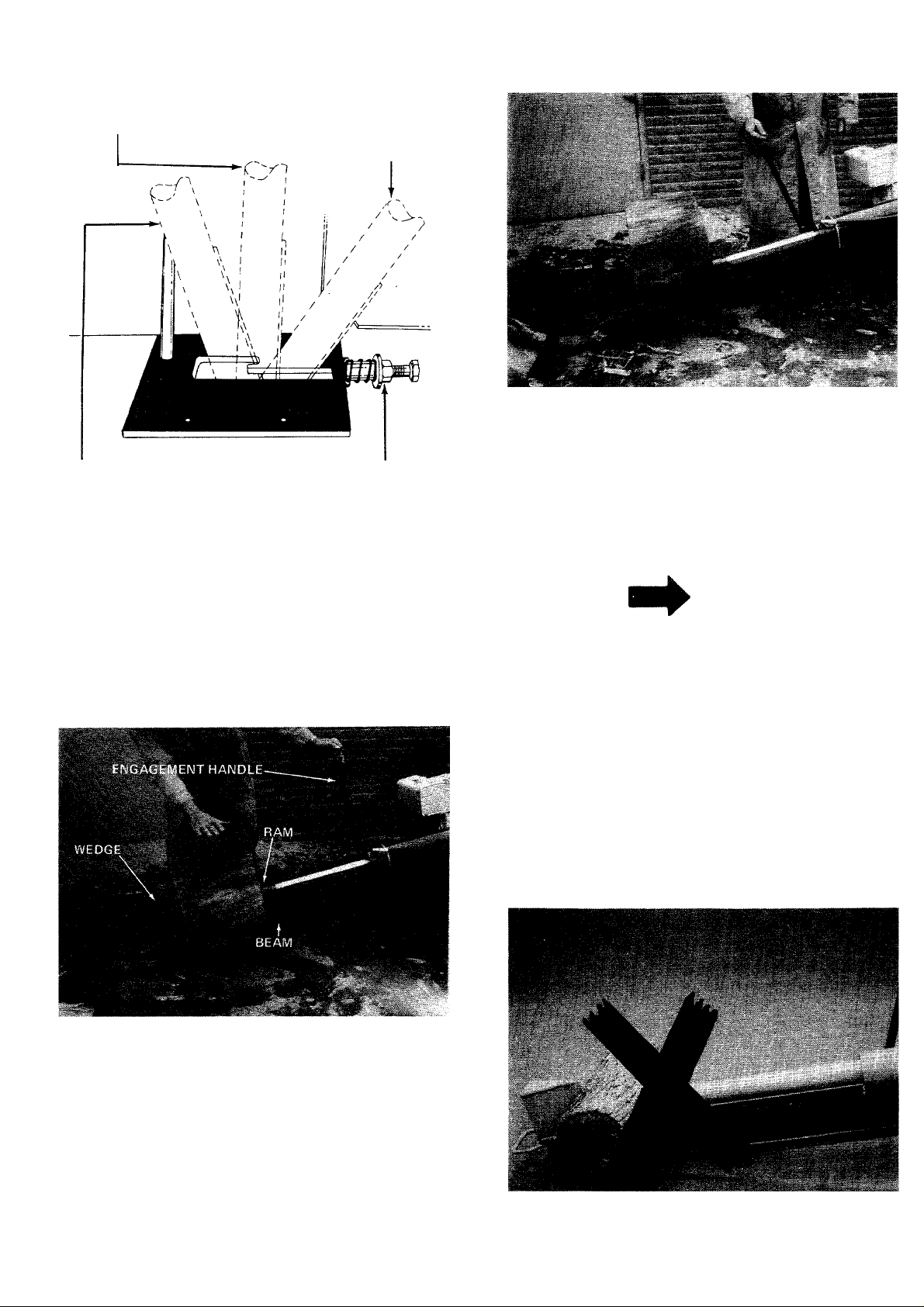
ENGAGEMENT HANDLE
IN NEUTRAL POSITION.
ENGAGEMENT HANDLE
LOCKED IN REVERSE
POSITION.
FIGURE 10
ENGAGEMENT HANDLE
HELD IN FORWARD
POSITION.
STROKE RETURN STOP
PLUNGER.
FIGURE 12
5. Move engagement handle forward until log is split.
6. Move the engagement handle to the rear to return
ram.
The ram should take approximately 12 seconds to
make a complete cycle. This speed may vary
depending on throttle setting and temperature of oil.
Maximum length that can be split is 26".
1. Set throttle at maximum speed.
2. Place log on beam and hold in place with right
hand. See figure 11.
NOTE
If you lock the engagement handle in the reverse slot,
the ram will return until it hits the return stroke stop
plunger, which will throw the engagement handle
into neutral automatically.
DANGER
Never attempt to cut a log in half
with the log splitter. See figure 13.
Never stand next to the ram when
operating. See figure 14. Always stand
behind the ram.
FIGURE 11
**'3. Slowly move engagement handle forward until
ram rests against log. Release engagement handle
(Neutral).
4. Remove your hand from the log and step behind
the ram. See figure 12.
FIGURE 13
Page 10
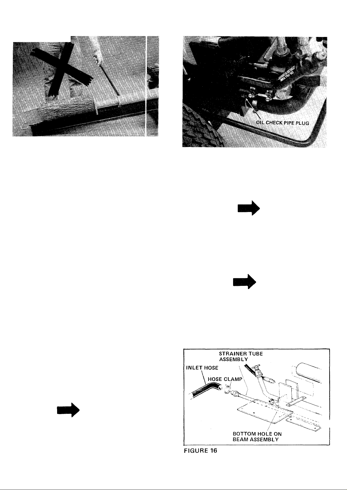
FIGURE 14
MAINTENANCE
FIGURE 15
Change oil in the reservoir every (100) hours of
operation.
1. Remove the hose clamp at inlet hose (bottom
hose on rear of beam). See figure 16.
WARNING I
®G
Always stop engine and disconnect
spark plug wire before performing any
maintenance or adjustments.
ENGINE OIL
Change oil first two (2) hours of operation and
check oil level every five (5) operating hours or each
time equipment is used.
Change oil every twenty-five (25) operating hours
or sooner if equipment is operated in exiremely
dusty or dirty conditions.
Refer to engine manual for quantity and type of oil.
LOG SPLITTER RESERVOIR OIL
Check oil in log splitter reservoir before every use.
See figure 15.
1. Block up front of log splitter so beam is evel.
2. Remove check pipe plug in rear of bearri. See
figure 15. If oil starts to come out of check pipe
plug hole, oil level is correct. IF IT DO El 5 NOT,
add oil to breather tube (see figure 8) until oil
starts out.
NOTE
Be prepared to catch oil in a suitable
container.
2. Pull off inlet hose from strainer tube assembly and
catch oil in a suitable container. See figure 16,
3. With an adjustable wrench remove the strainer
tube assembly. See figure 16.
NOTE
The strainer tube assembly is 53" long.
4. Drain oil, clean strainer tube and reassemble
using a hydraulic pipe sealant on the threads.
5. Remove the breather plug from breather tube.
See figure 8. Pour approximately 2-1 /2 gallons of
Dexron transmission fluid ONLY into breather
tube.
NOTE
Use hydraulic sealant tape or p pe
sealant on pipe plug threads.
3. Replace check pipe plug. Remove block from'
under front of beam.
10
Page 11
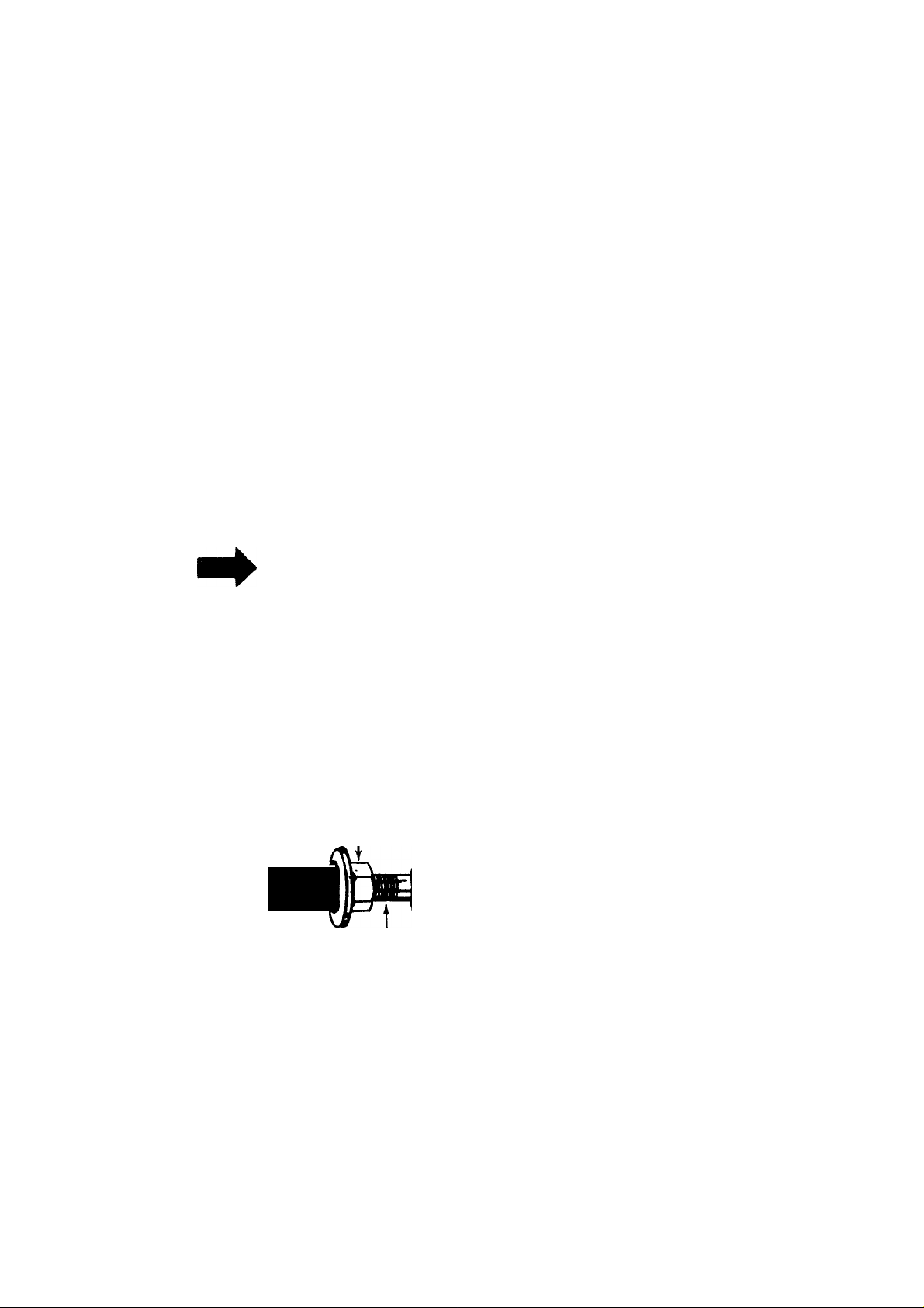
STRAINER TUBE ASSEMBLY
If the ram does not move back and forth smoothly,
the strainer tube assembly may be clogged.
^ To clean, follow instructions for changing the reservoir
; oil, step number 1 through 3. Clean the strainer tube
assembly and reassemble using a hydraulic pipe sealant
on the threads.
HOSE CLAMPS
Check the hose clamps on the bottom of the pump
for proper tightness before each use.
Hose clamps on the return hose should be checked
once a season.
STROKE RETURN STOP PLUNGER
If the engagement handle does not return to neutral
(from reverse) before the pressure relief bypass opens,
loosen the hex lock nut, and back out the hex bolt
one or two turns. See figure 17.
CARBURETOR ADJUSTMENTS
\ WARNING {
If any adjustments are made to the
engine while the engine is running
(e.g. carburetor), keep clear of all
moving parts. Be careful of heated
surfaces and muffler.
Refer to engine manual packed with your unit for
carburetor adjustment information.
INSTALLATION OF TIRE TO RIM
1. Lubricate tire beads and rim flanges.
2. Do hot exceed 30 P.S.I. when seating beads.
3. Adjust to recommended pressure after beads are
sealed.
NOTE
When the pressure relief valve opens,
a loud high pitched sound is heard and
engine labors.
Tighten hex lock nut and operate log splitter. Repeat
if necessary.
HEX LOCKNUT
iff I
STROKE RETURN STOP PLUNGER
FIGURE 17
HEX BOLT
OFF-SEASON STORAGE
In event engine is to be stored for any length of time
(30 days or more), prepare as follows:
1. Drain gasoline by tipping or by siphon hose,
then run engine until remainder is used and tank
and carburetor and empty.
A
Drain into container outdoors away
from fire or flame.
2. Drain carburetor by running engine until it stops
from lack of fuel.
3. Protect the inside of engine for storage by
removing spark plug and pouring one ounce of
SAE 30 oil through spark plug hole into cylinder.
Crank engine, without starting, several times to
spread oil over cylinder walls.
4. Never store outside without a waterproof cover.
CAUTION
RAM OPERATION
^ If the ram does not move smoothly, run the ram its
full stroke several times to'clear out air in the system.
Be sure the breather valve is open.
Ifthisdoes not correct the problem, see Strainer Tube
Assembly paragraph.
11
A
When storing any type of power equip
ment in an unventilated or metal
storage shed, care should be taken to
rust proof the equipment. Using a
light oil or silicone, coat the equip
ment, especially springs and bearings.
CAUTION
Page 12
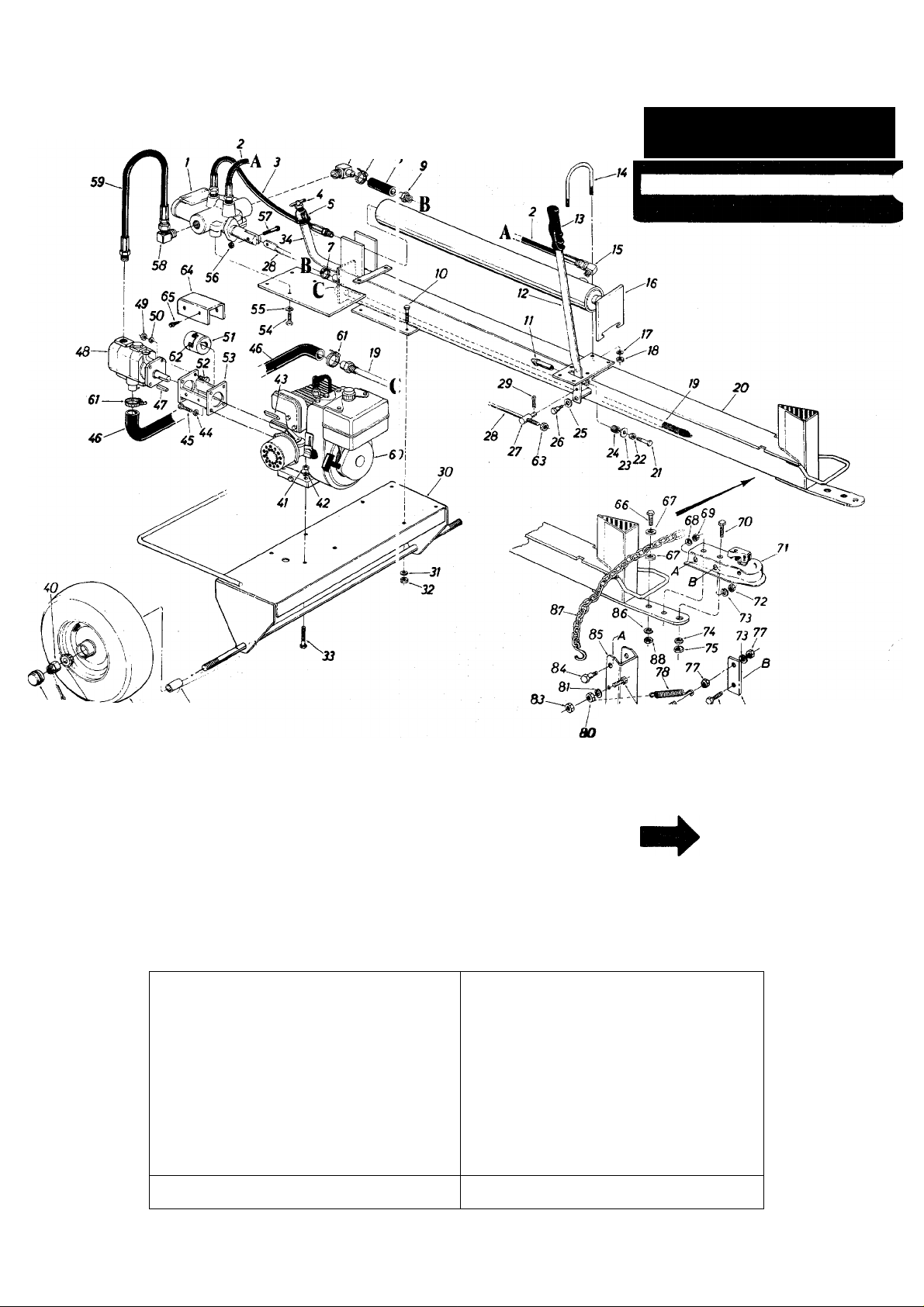
Models 642 and 645
^ 7
IF YOU WRITE TO US ABOUT THIS ARTICLE
OR IF YOU ORDER REPLACEMENT PARTS AL
WAYS MENTION THIS MODEL & SERIAL NO
MODEL
36 37 36
NOTE: The engine is not under warranty by
the log splitter manufacturer ... If repairs or
service is needed on the engine, please contact
your nearest authorized engine service outlet.
Check the "'Yellow Pages" of your telephone
book under" Engines — Gasoline".
*The hydraulic pump is one of two ty )es. As complete units, the two pumps are interchangeable
(refer to parts list for part number). If it is necessary to determine the specific type of pump
on your unit, refer to the illustrations jelow.
ALLEN
HEAD 5-
SCREWS
Find It l ast
In Ths
Yellow Pages
BOLTS (SW/
79
NOTE
This instruction manual covers various models and all
specifications shown do not necessarily apply to your
model. Specifications subject to change without notice
or obligation.
jjm
Nf
BARNES PUMP
FENNER STONE PUMP
12
Page 13

Models 642 and 645
PARTS LIST FOR LOG SPLITTER MODELS 642 and 645
REF.
N0.
1
PART NO.
717-0407
2 727-0231
727-0211
3
4
737-0161
5 737-0173
737-0153
6
7 726-0173
727-0210
8
737-0172
9
710-0117
10
738-0406
11
750-0428
12
08118
13
747-0355
14
747-0354
737-0152
15
16
736-0169
17
19
20
21
22
23
24
25
26
27
28
29
30
31
32
33
34
35
36
712-0798
15234 Strainer Tube Ass'y15235
710-0624
712-0123
736-0159
732-0252
736-0160
738-0143
711-0198
747-0297
714-0507
13747
736-0119
712-0123
710-0409
750-0501
750-0442
734-1016
H 18
734-1017
734-0872
37
38
39
40
41
741-0107
714-0121
734-0873
712-0299
712-0123
DESCRIPTION
Control Valve
Return Stroke High Pressure Hose
Forward Stroke High Pressure Hose
Breather Valve
REF.
NO.
42 736-0119 L.-Wash. 5/16" I.D.*
43 714-0128 Sq. Key 1/4" X 1/4" x 1.00" Lg.
44 736-0119 L-Wash. 5/16" I.D.*
45
Female Adapter 3/4-14 x 1/4-28 46
N.P.T.F.
Return Elbow
47
Hose Clamp 3/4" I.D.
Return Hose 3/4" I.D. x 2.62" Lg.
48
Nipple 1/2-14 N.P.T.F. x 1.5" Lg.
Hex Bolt 5/16-24 X 1.00" Lg.
(Grade 5)
Return Stroke Stop Plunger
Engagement Handle
Grip
Cylinder Support Rod (for 3-1/2"
Dia.) (642)
49 712-0123
50
51
52
53
54
55
Cylinder Support Rod (for 4" Dia.) 56
(645)
High Pressure 90° Elbow 3/8 N.P.T.
X 9/16-18
Cylinder Ass'y- (See Page 14 for
Breakdown)
L.-Wash. 3/8" I.D.*
Hex Nut 3/8-16 Thd.*
57
58
59
60
61
62
63
64
Complete Oil Tank & Beam
Hex Bolt 5/16-24 x 1.50" Lg.
Hex Nut 5/16-24 Thd.*
65
66
67 736-0262
Fl.-Wash. .34 I.D. x .88" O.D.
Compression Spring .64 0.D.x.81 Lg.
Fl.-Wash. .53" I.D. x .94" O.D.
Shid. Bolt .500" Dia. x .340
68
69
70 710-0191
Pivot Bushing
Engagement Rod .38 Dia. x 32" Lg.
Cotter Pin 3/32" Dia. x .75" Lg.*
Frame Ass'y.
L.-Wash. 5/16" I.D.*
Hex Nut 5/16-24 Thd.*
Hex Bolt 5/16-24 X 1.75" Lg.*
Filler Tube
Spacer .75" I.D.x 1.12" O.D.x1.56"
Lg-
Wheel Ass'y. Comp. 4.80/4.00 x 8
Wheel Rim Ass'y. (Service Only)
Tire Only 4.80/4.00x8(Service Only)
Tapered Roller Bearing (Service Only)
Cotter Pin 5/32" Dia. x 1.00" Lg.*
Hub Cap (Service Only)
Hex Castle Nut 3/4-16 Thd.
Hex Nut 5/16-24 Thd.
PART NO.
DESCRIPTION
710-0157 Hex Bolt 5/16-24 X .75" Lg.*
727-0228
Suction Hose (642)
727-0229 Suction Hose (645)
Woodruff Key (comes with Ref.
No. 48)
717-0460
717-0461
Pump with Woodruff Key (642)
Pump with Woodruff Key (645)
Hex Nut 5/16-24 Thd.*
736-0119 L.-Wash. 5/16" I.D.*
717-0462
Flexible Coupling
710-0117 Hex Bolt 5/16-24 X 1.00" Lg.*
13295
710-0216
736-0105
712-0107
710-0106
737-0171
727-0232
Coupling Support Brkt. Ass'y.
Hex Bolt 3/8-16 X .75" Lg.
Belleville Wash. 3/8" I.D.
Hex Cent. L.-Nut 1/4-20 Thd.
Hex Bolt 1/4-20 X 1.25" Lg.*
90° Solid Male Adapter
High Pressure Hose Ass'y.
Engine
726-0132
735-0205
712-0241
14806
710-0653
710-0539
Hose Clamp 1" I.D.
Spider
Hex Nut 3/8-24 Thd.
Coupling Shield
Hex Self Tap. Scr. 1/4-20 x .38"
Hex Bolt 3/8-24 X 1.75" Lg.*t
Fl.-Wash. 3/8" I.D. x 7/8" O.D. x .09
Thk.t
736-0329
712-0287
L.-Wash. 1/4" I.D.*t
Hex Nut 1/4-20 Thd.*t
Hex Bolt 3/8-24 X 1.25" Lg.*t
71 727-0289
712-0267
72
736-0119
73
736-0217
74
712-0241
75
710-0118
76
712-0267
77
732-0352
78
710-0442
79
712-0138
80
81
82
83
84
85
86
87
88
89
736-0329
710-0299
712-0117
738-0255
15850
736-0217
713-0338
712-0241
781-0010
Tow Hitch Ass'y. Comp.t
Hex Nut 5/16-18 Thd.*t
L.-Wash. 5/16" I.D.*t
L.-Wash. 3/8" I.D.*t
Hex Nut 3/8-24 Thd.*t
Hex Bolt5/16-18x.75" Lg.*t
Hex Nut 5/16-18 Thd.*t
Extension Springt
Hex Bolt 5/16-18 X 1.50" Lg.*
Hex Nut 1/4-28 Thd.*T
L.-Wash. 1/4" I.D.*t
Hex Bolt 1/4-28 x 1.00" Lg.t
Hex L.-Nut 1/4-28 Thd.
ShId. Bolt 374" Dia. x .171" Lg.t
Flip Stand Brackett
L.-Wash. 3/8" I.D.*t
Chain 40" Lg. Tow Hitcht
Hex Nut 3/8-24 Thd.*t
Spring Mtg. Brackett
* For faster service order standard nuts, bolts, and washers locally. If these items cannot be obtained locally, order by part number and
size as shc^n on parts list.
t Optional Parts.
13
Page 14
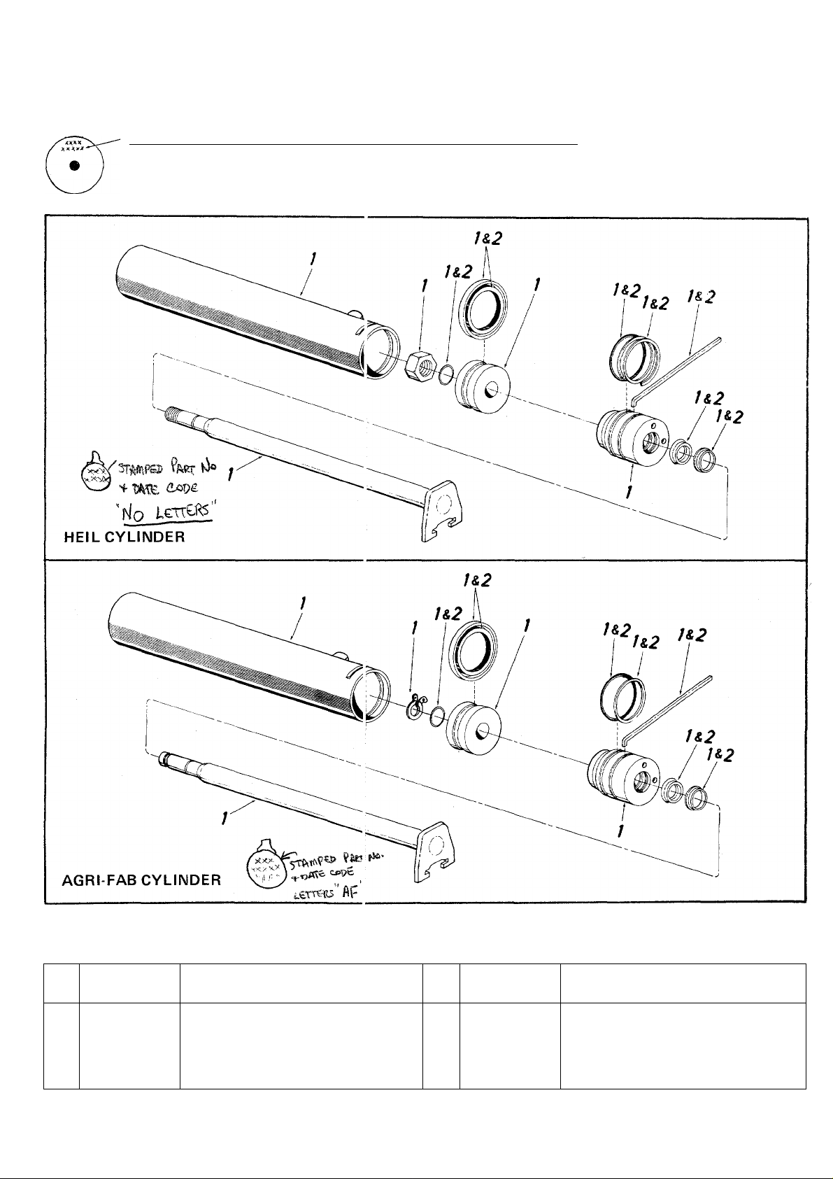
Models 642 and (»45
STAMPED PART NUMBER AND DATE CODE ON END OF CYLINDER
Letters "AF" - AGRI-FAB - Requi es 0-Ring Kit 753-0372 (3-1/2" Cylinder), 753-0373 (4" Cylinder)
No Letters - HEIL - Requires 0-Rin j Kit 753-0271 (3-1/2" Cylinder), 753-0263 (4" Cylinder)
REF.
NO.
1
2
PARTS LIST FOR MODEL 642
PART NO.
717-0459
753-0271
753-0372
3-1/2" DIA. CYLINDER
DESCRIPTION
Cylinder Ass'y-Comp.
3-1/2" Cyl. Kit "0"-Rinc Set
(Heil)
3-1/2" Cyl. Kit "0"-Rinc Set 753-0373
(Agri-Fab)
REF.
NO.
1 717-0406
753-0263
2
14
PART NO.
4" DIA. CYLINDER
PARTS LIST FOR MODEL 645
DESCRIPTION
Cylinder Ass'y- Comp.
4" Cyl. Kit "0"-Ring Set
(Heil)
4" Cyl. Kit "0"-Ring Set
(Agri-Fab)
Page 15

TROUBLE SHOOTING CHART
SYMPTOM
Engine fails to start
1.
Hard starting or loss of
2.
power.
Engine overheats
3.
Will not split logs
4
POSSIBLE CAUSE(S)
Check fuel tank for gas. A.
A.
Spark plug lead wire
B.
disconnected.
Faulty spark plug.
C.
Spark plug wire loose.
A.
Dirty air cleaner. B.
B.
Carburetor not adjusted
A.
properly.
Air flow restricted. B.
B.
Engine oil level low.
C.
Relief valve setting
A.
incorrect.
Pump setting incorrect.
B.
SOLUTION
Fill tank if empty.
Connect lead wire.
B.
Spark should jump gap between
C.
control electrode and side electrode.
If spark does not jump, replace the
spark plug.
Connect and tighten spark plug wire.
A.
Clean air cleaner as described in
engine manual.
Adjust carburetor. See engine manual.
A.
Remove blower housing and clean as
described in the engine manual.
C.
Fill crankcase with the proper oil.
Shim valve with .010 flat washer.
A.
Adjust pump setting.
B.
Replace seals.
Leaking cylinder
5.
Broken seals.
A.
Scored cylinder. B.
B.
A.
Replace cylinder.
NOTE: For repairs beyond the minor adjustments listed above, please contact your local service dealer.
15
Page 16

PARTS iNFORMATION
POWER EQUIPMENT PARTS AND SERVICE
Parts and service are available through the authorized service
firms listed below. All orders should specify the model nurr ber of
your unit, part numbers, description of parts and the quantity of
each part required.
NOTE: If any parts are found to be missing or c efective upon assembly of this unit, write to advise the factory so
that immediate replacement can be made.
ALABAMA BIRMINGHAM
Auto Electric & Carburetor Co. ... 2625 4th Ave. S
ARKANSAS NORTH LITTLE ROCK
Sutton’s Lawn Mower Shop
CALIFORNIA PORTERVILLE
Billious.......................................... 75 North D Street ....
COLORADO DENVER
Spitzer Industrial Products Co. ... 6601 N.
FLORIDA JACKSONVILLE
Radco Distributors............................ 4909 Victor St.
Small Eng. Dist
GEORGIA EAST POINT
East Point Cycle & Key..................... 2834 Church St
ILLINOIS LYONS
Keen Edge Co
INDIANA ELKHART
Parts & Sales Inc
IOWA DUBUQUE
Power Lawn & Garden Equip
LOUISIANA MONROE
Mid-South Power
Suhren Engine Co
MARYLAND TAKOMA PARK
Center Supply Co.............................. 6867 New Hampshire
MASSACHUSETTS SPRINGFIELD
Morton B. Collins Co......................... 300 Birnie Ave
MICHIGAN LANSING
Lorenz Service Co
Power Equipment Dist....................... 340 Hubbard
MINNESOTA HOPKINS
Hance Distributing Inc
MISSISSIPPI BILOXI
Biloxi Sales & Service, Inc................ 506 Caillavet St
MISSOURI KANSAS CITY
Automotive Equip. Service ...............3117 Holmes St
Ross-Frazier Supply Co
Henzier, Inc........................................ 2015 Lemay Ferry Rd.
NEW JERSEY BELLMAWR
Lawnmower Parts Inc
NEW MEXICO ALBUQUERQUE
Spitzer Eng. & Parts
NEW YORK CARTHAGE
Gamble Dist., Inc
........................ 2351 N.W. 147th St. ..
..................................
...............................
.............................
............................
.........................
..............................
..............
...........
......................
....................
.......................
.........................
5301 Roundtop Drive
Box 368, Rt. 4
Washington St..............
Box 5459 .....................
OPA LOCKA
8615 Ogden Ave............
2101 Industrial Pkwy..
2551 J.F. Kennedy ...
1500 Arkansas St. ...
NEW ORLEANS
8330 Earhart Blvd. ...
2500 S. Pennsylvania .
MOUNT CLEMENS
420 Excelsior Ave. W.
ST. JOSEPH
8th and Monterey
ST. LOUIS
717 Creek Rd
1023 Third Ave. N.W. .
West End Ave
..................
..............
.............
...........
...............
..............
................
............
.........
..................
..................
35233 Smith Hardware Co.............................515 N. George St
72117 OHIO CARROLL
93257 CLEVELAND
80229 National Central
32207 Box 929
33054 Victory Motors, Inc
30344 Kenton Supply Co
60534 EECOInc
46516 Thompson Rubber Co
52001 BluemontCo
71201 Frank Roberts & Sons
70118 Scranton Auto Ignition Co
20912 MEMPHIS
01107 TEXAS DALLAS
48910 fort worth
48043 HOUSTON
55343 SAN ANTONIO
39533 P.O. Box 17867
64109 A-1 Engine & Mower Co
64503 RBI Corp
..........
63125 Bailey’s Inc..........................................1414 14th Ave
08030 Automotive Supply Co
87103 CHILTON
13619
BRIGGS AND STRATTON, TECUMSEH AND PEERLESS PARTS
AND SERVICE
Briggs & Stratton, Tecumseh and Peerless parts and service
should be handled by your nearest authorized engine service firm.
Check the yellow pages of your telephone directory under the
listing Engines—Gasoline, Briggs & Stratton or Tecumseh
Lauson,
NORTH CAROLINA GOLDSBORO
Dixie Sales Company
Stebe’s Mid-State Mower Supply . Box 366, 71 High St... .43112
Bleckrie, Inc
Burton Supply Co..............................1301 Logan Ave.
OKLAHOMA MUSKOGEE
OREGON PORTLAND
PENNSYLVANIA HARRISBURG
TENNESSEE KNOXVILLE
Master Repair Service
American Sales & Service, Inc. ... 3035-43 Bellbrook ... .38116
Marr Brothers, Inc
Woodson Sales Corp
Bullard Supply Co
Engine House Inc
UTAH SALT LAKE CITY
VIRGINIA ASHLAND
WASHINGTON SEATTLE
WISCONSIN APPLETON
Horst Dist.......................................... 444N.Madison
......................................
.............................................
........................................
.............................................
........................
..................................
..............................
...............................
.................. 5222-24 N. Fifth St........19120
.......................
...................
.....................
...............................
........................
.............................
.............................
.....................
........................
GREENSBORO
335 N. Green
7900 Lorain Ave
WADSWORTH
687 Seville Rd
YOUNGSTOWN
.........................
605 S. Cherokee...........74401
8216 N. Denver Ave. .. .97217
4021 N. 6th St
PHILADELPHIA
PITTSBURGH
11125 Frankstown Rd. .15235
PUNXSUTAWNEY
R.D. 2
.............................
SCRANTON
1133-35 Wyoming Ave. 18509
2000 Western Ave
423 E. Jefferson
1702 N. Sylvania
2409 Commerce St. .. .77003
8610 Botts Lane
439 E. 900 So
101 Cedar Run Dr
123 S. Lin wood Ave.
P.O. Box 798
...........
27530
................
........... .44281
...............
...............
................
................
...............
..............
........
..........
..........
.......
.78217
..........
27402
44102
44501
17110
15767
37921
75203
76111
84111
23005
98122
54911
53014
WARRANTV PARTS AND SERVICE POLICY (0483)
The purpose of warranty is to protect the customer f ron defects in workmanship and materials, defects which are NOT detected at the
time of manufacture. It does not provide for the unlimited and unrestricted replacement of parts. Use and maintenance are the respon
sibility of the customer. The manufacturer cannot assui ne responsibility for conditions over which it has no control. Simply put, if it’s
the manufacturer’s fault, it’s the manufacturer’s respons ibility; if it’s the customer’s fault, it’s the customers’s responsibility.
CLAIMS AGAINST THE MANUFACTURER’S WARRANT’ ’
INCLUDES:
1. Replacement of Missing Parts on new equipment.
2. Replacement of Defective Parts within the warranty leriod.
3. Repalrof Defects within the warranty period.
MTD PRODUCTS INC
P.O. BOX 36900 • CLEVELAND, OHIO 44136
All claims MUST be substantiated with the following
information:
1. Model Number of unit involved.
2. Date unit was purchased or first put into service.
3. Date of failure.
4. Nature of failure.
 Loading...