

Page 1

.50
ASSEMBLY
OPERATION
MAINTENANCE
PARTS LIST
IMPORTANT:
Read Safety Rules
and Instructions
PRINTED IN U.S.A.
MODEL NUMBER
130-360A
25"
RIDING
MOWER
FORM NO. 770-0216
Page 2

INDEX
Safe Operation Practices
Assembly Instructions
Controls
Operating Instructions
Adjustments...........................................................9
Maintenance...................................................... 10
Belt Replacement
................................................................7
...............................................
......................................
...........................................
...........................................
r
♦
♦
♦
♦
♦
♦
♦
♦
♦
♦
♦
♦
For one year from the date of original retail purchase, MTD PRODUCTS INC will either
repair or replace, at its option, free of charge, F.O.B. factory or authorized service firm,
any part or parts found to be defective in material or workmanship. Transportation charges
for any parts submitted for replacement under this warranty must be paid by the purchaser
unless such return is requested by MTD PRODUCTS INC.
This warranty will not apply to any part which has become inoperative due to misuse,
excessive use, accident, neglect, improper maintenance, alterations, or unless the unit
has been operated and maintained in accordance with the instructions furnished. This
warranty does not apply to the engine, motor, battery, battery charger or component parts
thereof. Please refer to the applicable manufacturer’s warranty on these items.
This warranty will not apply where the unit has been used commercially.
Warranty service is available through your local authorized service dealer or distributor. If
you do not know the dealer or distributor in your area, please write to the Customer Service
Department of MTD.
LIMITED WARRANTY
11
3
4
8
Off-Season Storage
Trouble Shooting Chart.........................................15
Repair Parts Transmission
Wiring Diagram....................................................17
Repair Parts
Wheel Chart....................................................... 25
Parts Information
........................................................
..............................................
................................
...................................
Back Cover
14
16
18
♦
♦
♦
♦
♦
♦
♦
♦
♦
♦
♦
♦
♦
♦
♦
♦
♦
The equipment which you have just purchased does not have a spark arrester. If this equipment is used on
any forest covered land, brush covered land, or grass covered unimproved land in the State of California,
before using on such land, the California law requires that a spark arrester be provided. In addition, spark
arrester is required by law to be in effective working order. The spark arrester must be attached to the
exhaust system and comply with Section 4442 of the California Public Resources Code.
The return of a complete unit will not be accepted by the factory unless prior written
permission has been extended by MTD.
This warranty gives you specific legal rights. You may also have other rights which vary
from state to state.
TO PURCHASERS
OF INTERNAL COMBUSTION ENGINE EQUIPPED
MACHINERY OR DEVICES IN THE STATE OF CALIFORNIA
♦
♦
♦
♦
>
Page 3

IMPORTANT
It is suggested that this manual be read in its entirety before attempting to assemble or operate. Keep this
manual in a safe place for future reference and for ordering replacement parts.
This unit is shipped WITHOUT GASOLINE or OIL After assembly, see operating section of this manual for
proper fuel and amount.
This unit is a precision piece of power equipment, not a plaything. Therefore exercise extreme caution at
all times.
SAFE OPERATION PRACTICES FOR RIDING VEHICLES
1. Know the controls and how to stop quickly—
READ THE OWNER’S MANUAL.
2. Do not allow children to operate vehicle. Do
not allow adults to operate it without proper
instruction. Only persons well acquainted
with these rules of safe operation should be
allowed to use your mower.
3. Do not carry passengers
4. Keep the area of operation clear of all per
sons, particularly small children and pets.
Stop engine when they are in the vicinity of
your mower. Although the area of operation
should be completely cleared of foreign ob
jects, a small object may have been over
looked and could be accidently thrown by the
mower in any direction.
5. Clear work area of objects which might be
picked up and thrown by the mower in any
direction.
6. Disengage all attachment clutches and shift
into neutral before attempting to start engine.
7. Disengage power to attachment(s) and stop
engine before leaving operating position.
8. Disengage power to attachment(s) and stop
engine before making any repairs or ad
justments. Disconnect the spark plug wire
and keep the wire away from the plug to pre
vent accidental starting.
9. Before attempting to unclog the mower or
discharge chute, stop the engine and be sure
the blade(s) have stopped completely. Discon
nect the spark plug wire and keep the wire
away from the plug to prevent accidental start
ing.
10. Disengage power to attachment(s) when
transporting or not in use.
11. Take all possible precautions when leaving
vehicle unattended such as disengaging
power-take-off, lowering attachments, shift
ing into neutral, setting parking brake, stop
ping engine and removing key.
12. Do not stop or start suddenly when going
uphill or downhill. Mow up and down face of
steep slopes; never across the face.
13. Reduce speed on slopes and in sharp turns to
prevent tipping or loss of control. Exercise ex
treme caution when changing direction on
slopes.
14. Stay alert for holes in terrain and other hidden
hazards.
15. Use care when pulling loads or using heavy
equipment.
A. Use only approved drawbar hitch points.
B. Limit loads to those you can safely control.
C. Do not turn sharply. Use care when back- 3
ing.
D. Use counterweight(s) or wheel weights
when suggested in owner’s manual.
16. Watch out for traffic when crossing or near
roadways.
17. When using any attachments, never direct dis
charge of material toward bystanders nor
allow anyone near vehicle while in operation.
18. Handle gasoline with care. It is highly flam
mable.
A. Use approved gasoline container.
B. Never remove cap or add gasoline to a run
ning or hot engine or fill fuel tank indoors.
Wipe up spilled gasoline.
C. Open doors if engine is run in garage. Ex
haust fumes are dangerous. Do not run
engine indoors.
19. Keep the vehicle and attachments in good
operating condition, and keep safety devices
in place. Use guards as instructed in owner’s
manual.
20. Keep all nuts, bolts, and screws tight to be
sure the equipment is in safe working condi
tion.
21. Never store the equipment with gasoline in
the tank inside a building where fumes may
reach an open flame or spark. Allow engine to
cool before storing in any enclosure.
22. To reduce fire hazard, keep engine free of
grass, leaves or excessive grease.
23. The vehicle and attachments should be stop
ped and inspected for damage after striking a
foreign object. The damage should be
repaired before restarting and operating the
equipment.
24. Do not change the engine governor settings
or overspeed the engine.
25. When using the vehicle with mower, proceed
as follows:
(1) Mow only in daylight or in good artificial
light.
(2) Never make a cutting height adjustment
while engine is running if operator must
dismount to do so.
(3) Shut the engine off and wait until the
blade comes to a complete stop before
removing the grass catcher.
(4) Check blade mounting bolts for proper
tightness at frequent intervals.
26. Check grass catcher bags frequently for wear
or deterioration. For safety protection, replace
only with new bag meeting original equipment
specifications.
27. Look behind to make sure the area is clear
before placing the transmission in reverse
and backing up.
Page 4
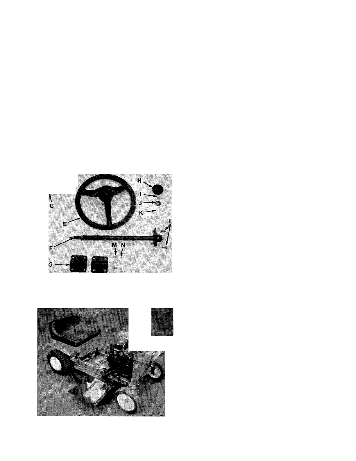
FIGURE 1.
^ K D
B
TOOLS REQUIRED FOR ASSEMBLY
-See figure 1.
A (1) V2" Box or Open End Wrench
i :
B (1) V4 " Flat Screwdriver
C (2) 7/16" Box or Open End Wrench
V
PARTS IN CARTON AND HARDWARE PACK
ASSEMBLY
X
-See figure 2.
A (2) Truss Head Screws V4- 20 x 5/8" Long
B (2) Truss Head Screws V4-20 x V2" Long
C (4) Hex Nuts 1/4-20 Thread
D (4) Lock Washers V4" I.D.
E (1) Steering Wheel
F (1) Steering Shaft Assembly
G (2) Tube Clamps
H (1) Steering Wheel Cap
I (1) Hex Nut 5/16-18 Thread
J (1) Belleville Washer
K (1) Wave Washer
L (2) Hex Sems Bolts 5/16-18 x 3/4" Long
M (4) Hex Bolts 1/4-20 X 5/8" Long
N (4) Hex Lock Nuts V4-20 Thread
FIGURE 2.
FIGURE 3.
■^NOTE
Reference to right-hand or left-hand
side of machine is from the driver’s
seat facing forward.
CAUTION
A
Do not use rear plastic cover to lift
unit.
TIRE PRESSURE
FOR SHIPPING PURPOSES, THE TIRES ON YOUR
UNIT MAY BE OVER-INFLATED. TIRE PRESSURE
SHOULD BE REDUCED BEFORE UNIT IS PUT IN
TO OPERATION. PRESSURE SHOULD BE AP
PROXIMATELY 15 P.S.I. EQUAL TIRE PRESSURE
SHOULD BE MAINTAINED. MAXIMUM TIRE
PRESSURE 30 P.S.I.
Page 5
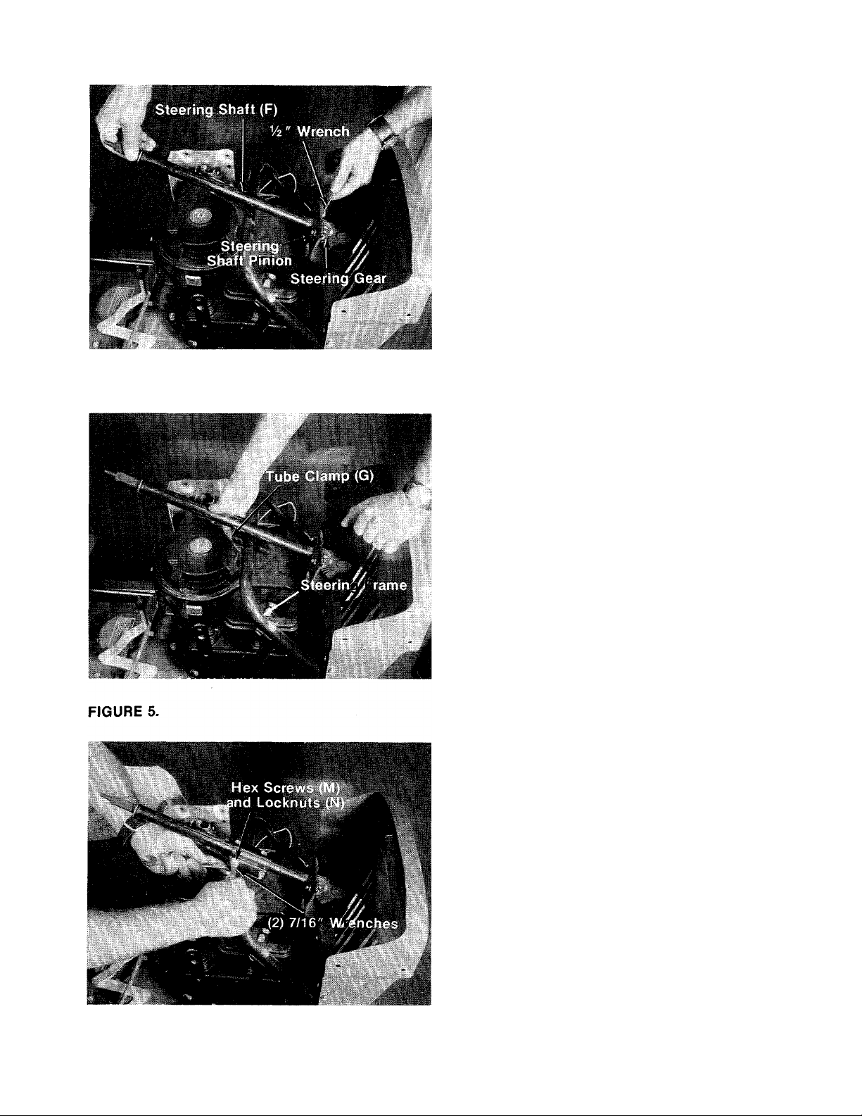
FIGURE 4.
■1. Place steering shaft (F) pinion in steering gear
and fasten with two hex sems bolts (L). A V2"
wrench is required. See figure 4.
■2. Place one tube clamp (G) under steering
frame. See figure 5.
FIGURE 6.
■3. Place the other tube clamp (G) on top of steer
ing shaft and secure with four hex screws (M)
and hex lock nuts (N). Two 7/16" wrenches are
required. See figure 6.
Page 6

FIGURE 7.
'1 ■■ V. ^ >4* i
Tiuss Scrpw Truss Screw
(B) (A)
‘ I \
■ ■«; lb-
Vi* ' >■
.* »■
4. Assemble the hood with 5/8" truss screws (A)
to the rear of hood, and the Vz" long truss
—screws (B) to the front of hood. Fasten with
lock washers (D) and hex nuts (C) to the in
side. See figure 7.
5. Place wave washer (K), steering wheel (E),
— belleville washer (J), over end of steering shaft
and secure with hex nut (I), using a Vz"
wrench. See figures 8 and 9.
FIGURE 8.
FIGURE 9.
Hex Nut (I)
Belleville
-w* Washer iJ>
Steering
Wheel (E)
NOTE
It may be necessary to reach inside
the hood and push up on steering
shaft to get the steering wheel on.
6. Place steering wheel cap (H) in position and
press by hand.
Page 7
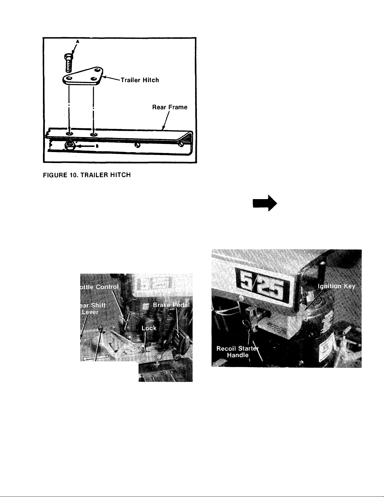
7. Position the trailer hitch on the center of the
rear frame section and fasten with bolts A and
— nuts B. See figure 10.
8. Check ALL nuts and bolts for correct
tightness.
CONTROLS
The controls on your mower may be considered as
the Throttle Control, Recoil Starter Handle, Igni
tion Key, Blade Engagement Lever, Brake Pedal,
Clutch Pedal and the Gear Shift Lever.
A. Throttle Control actuates the butterfly in the
carburetor and may be set at “CHOKE”,
“FAST” or “SLOW.” See figure 11.
'.J
.1
Blade Enqagement i
' Lever
NOTE
The clutch must be disengaged, the
blade must be disengaged and the
ignition key must be on before the
engine will start.
FIGURE 12.
FIGURE 11.
B. The Recoil Starter Handle is located on the left
hand side of the hood. To operate the Recoil
Starter Handle, twist it until it is in the horizon
tal position and pull to start the engine. After
the engine starts, return the Recoil Starter
Handle to the mounting bracket and turn it to
the vertical position as shown in figure 12.
C. The Ignition Key must be turned to the right to
the “ON” position before the Recoil Starter
Handle is pulled to start the engine. Turn the
Ignition Key to the left to the “OFF” position to
stop the engine. See figures 12 and 13.
D. The Blade Engagement Lever engages and
disengages the blade. Pull the Blade Engage
ment Lever back to stop the blade. Move the
Blade Engagement Lever forward to engage
the blade. See figure 11.
Page 8
NOTE
Engage the
Lever slowly.
FIGURE 13.
E. The Gear Shift Lever is used to select either
forward or reverse. See figure 11.
Blade
Engagement
OPERATING
INSTRUCTIONS
CAUTION
1. KEEP ALL SHIELDS & GUARDS IN PLACE
2. BEFORE LEAVING OPERATOR’S POSITION:
SHIFT CONTROLS INTO NEUTRAL
SET PARKING BRAKE
OISENGAGE ATTACHMENT DRIVE
SHUT ENGINE OFF
REMOVE IGNITION KEY
3. WAIT FOR ALL MOVEMENT TO STOP BEFORE
SERVICING MACHINE
4. KEEP PEOPLE & PETS A SAFE DISTANCE
AWAY FROM MACHINE
CAUTION
DO NOT OPERATE
MOWER UNLESS
NOTE
Do not shift gears whiie in motion.
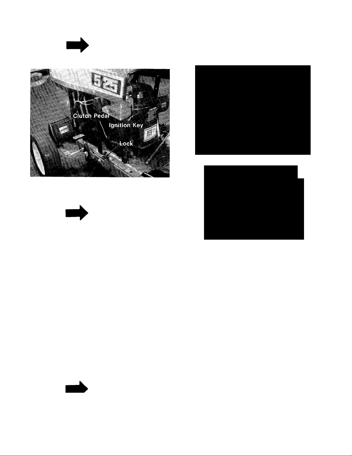
F. The Clutch Pedal is operated with your left
foot. The Clutch Pedal, when depressed,
disengages the engine from the transmission
so you can stop the movement of the rider
mower to shift gears. The Ciutch Pedal can be
locked in the DISENGAGED position by
depressing the Ciutch Pedal and lifting the
clutch lock with your left hand. To release the
Clutch Pedal, depress it with your foot. See
figure 13.
G. The Brake Pedal is operated with your right
foot and is used to stop the forward or reverse
motion of the rider. To engage the brake,
depress the Brake Pedal with your right foot.
To set the parking brake, depress the brake
and lift the lock. To release, depress the brake
pedal. See figure 11.
CAUTION
A
Parking brake must be disengaged
before unit is put into motion.
___
NOTE
Unit is equipped with separate
brake and clutch pedals. To effi
ciently stop, it is necessary to dis
engage clutch when applying
brakes.
GUARD OR ENTIRE
GRASS CATCHER IS
IN ITS PROPER PLACE.
STARTING THE ENGINE
1. Be sure the crankcase is filled with oil as
recommended in the engine manaul. Put
regular gasoline in the gasoline tank.
2. Attach the wire to the spark plug.
3. Depress the Brake Pedal and lock it down with
lock. See figure 11.
4. Depress the Clutch Pedal and lock it down
with lock. See figure 13.
5. Place the Gear Shift Lever in “NEUTRAL” (N)
position. See figure 11.
6. Place the Blade Engagement Lever in the
“OFF” disengaged position. See figure 11.
7. Place the Throttle Control Lever in the
“CHOKE” position. See figure 11.
8. Turn the Ignition Key to “ON” position. See
figure 12.
9. Twist the Recoil Starter Handle until it is free
and pull it with a quick steady motion. After
the engine starts, return the Recoil Starter
Handle and twist it until it locks. See figure
12.
10. Slowly return the throttle to the running posi
tion as soon as the engine starts.
Page 9
NOTE
If the Recoil Starter Handle is not
locked after engine starts, putting
the rider into motion will stop the
engine.
PUTTING THE RIDER IN MOTION
1. Advance the Throttle Control from % to
FULL throttle to prevent strain on the engine
and to operate the cutting blade.
2. Depress the Clutch Pedal so the clutch lock
releases.
3. Depress the Brake Pedal so the brake lock
releases.
4. Place the Gear Shift Lever in the “FORWARD”
position.
5. Slowly release the Clutch Pedal.
6. To stop the rider, depress the clutch and
brake pedals.
7. The blade can be engaged either while moving
or while standing still. Move the Blade
Engagement Lever forward slowly until the
blade is running.
STOPPING
Engine—Turn the Ignition Key to the left to the
“OFF” position.
Rider—Depress the clutch and brake pedals.
Blade—Move the Blade Engagement Lever all the
way to the rear of unit.
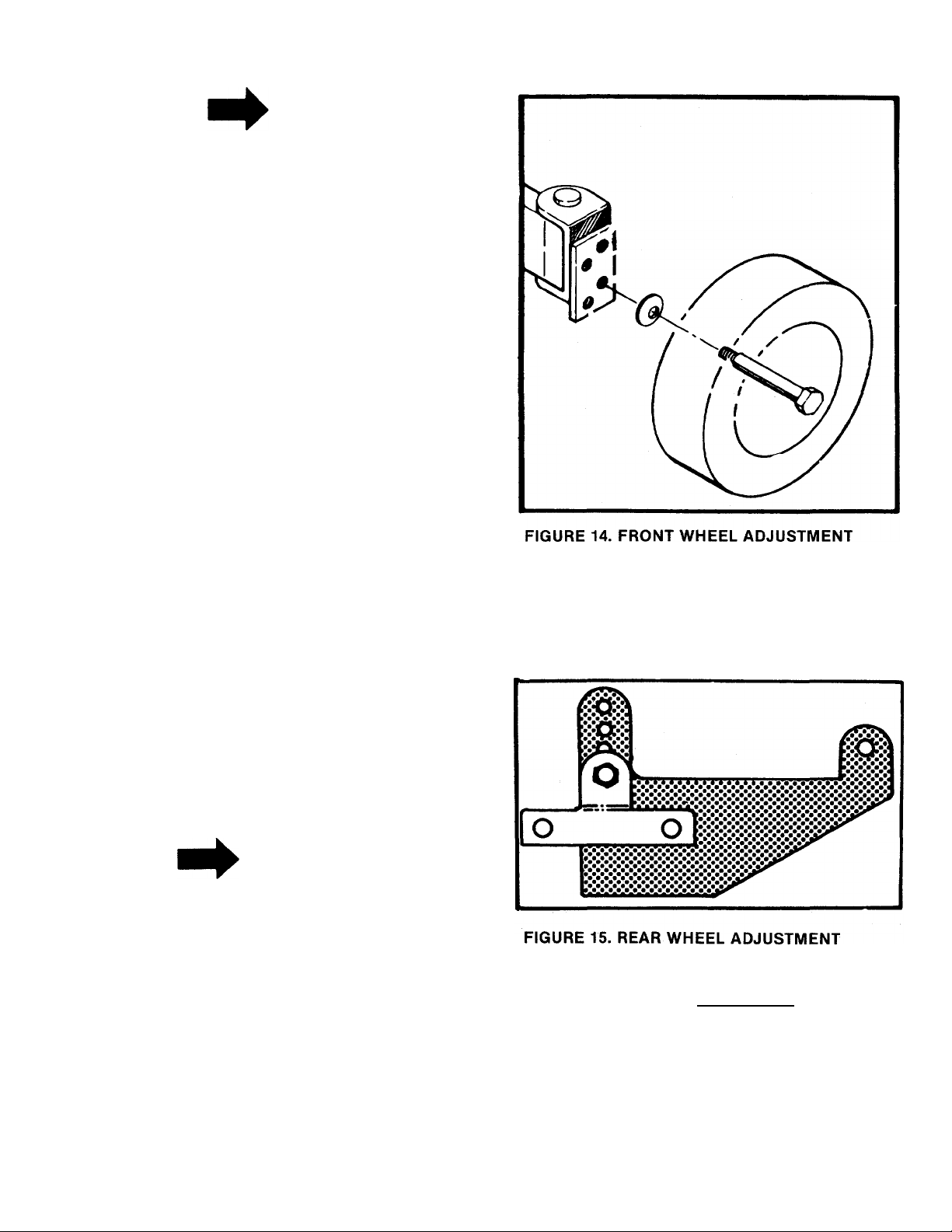
2. The height adjustment on the rear wheels is
made by removing the bolt on the height ad
justment on each side of the rear axle and
selecting one of the four positions. See figure
15.
IMPORTANT
After striking a foreign object, stop
the engine. Remove wire from spark
plug, thoroughly inspect the mower
for any damage, and repair the dam
age before restarting and operating
the mower.
ADJUSTMENTS
1. The height adjustment for the cutting blade is
made by removing the front axle bolts and
moving the front wheels to one of the four cut
ting positions. See figure 14.
\ WARNING \
If any adjustments are made to the
engine while the engine is running
(e.g. carburetor), disengage all
clutches and blades. Keep clear of
all moving parts. Be careful of
heated surfaces and muffler.
Page 10
MAINTENANCE
CRANKCASE OIL
I WARNING {
Remove the spark plug lead before
performing any maintenance on the
machine.
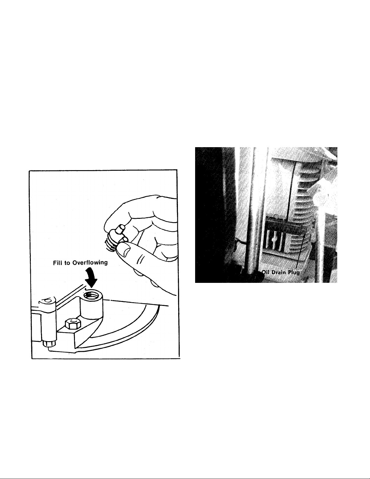
a. Oil Check
Check the oil level in the crankcase before each
use of the machine and after every two hours of
operation. Keep the oil level to the overflowing
point. See figure 16.
Step 1. With the machine on level ground, place a
suitable metal container under the oil
drain plug located on the front of the
engine. See figure 17.
Step 2. After the oil has been drained completely
from the crankcase, replace the drain plug
and tighten.
Step 3. With the machine on level ground, remove
the oil filler plug. See figure 16. Fill the
crankcase until the oil overflows from the
oil fill hole. Fill slowly to avoid air locks.
The crankcase holds approximately 1%
pints of good quality SAE 30 type MS
engine oil. Replace the oil filler plug.
FIGURE 16. OIL FILL
b. Oil Change
After the first two hours of operating a new
engine, drain the oii from the crankcase while the
engine is still hot and refill the crankcase with
new oil; thereafter, change the oil after every 25
hours of operation. This procedure ensures
minimum wear of engine parts and provides
virtuaily trouble-free operation. To change the oil,
proceed as follows:
FIGURE 17. OIL DRAIN
LUBRICATION
a. Steering Gears. Lubricate with multi-purpose
automotive type grease once a season.
b. Front Wheel Bearings. Once a season, remove
the front axle bolts and coat the axle with a
multi-purpose automotive type grease and
reassemble. See figure 18.
c. King Pins. Lubricate the king pins after every
25 hours of operation with SAE 30 oii. Wipe up
excessive oil with a rag. See figure 18.
d. Rear Axle Bearings. Lubricate the rear axle
bearings after every 25 hours of operation with
SAE 30 oil. Wipe up excessive oil with a rag.
See figure 19.
e. Chain. Remove the chain once each season,
clean in kerosene, dry and lubricate with a rag
saturated in SAE 30 oil. See figure 19.
f. Transmission. The transmission has been
lubricated at the factory and does not need to
be checked.
10
Page 11
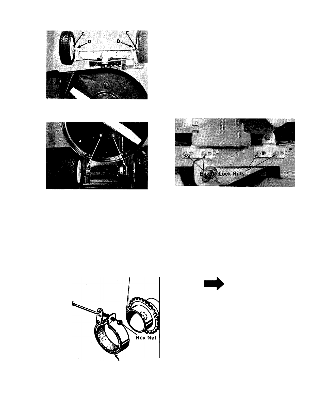
FIGURE 18. LUBRICATION
CHAIN ADJUSTMENT
The chain may require adjustment after a period of
use. Chain adjustment may also be necessary
when the height adjustment is changed. The chain
is adjusted as follows:
Step 1. Loosen elastic lock nuts on two rear ad
justment wheel hanger supports.
Step 2. Move rear axle assembly forward or back
ward as needed to make the proper
adjustment. •
Step 3. Tighten elastic lock nuts securely. See
figure 21.
FIGURE 19. LUBRICATION
BRAKE ADJUSTMENT
The brake adjustment is made by tightening the
hex nut on the brake band to compensate for
wear. Turn the hex nut one half turn and test the
brakes. Repeat until the brake is adjusted. See
figure 20.
Brake Drum
FIGURE 21. CHAIN ADJUSTMENT
REAR WHEELS
CAUTION
A
Installation of tire to rim:
1. Lubricate tire beads and rim
flanges.
2. Do not exceed 30 P.S.I. when
seating beads.
3. Adjust to recommended pres
sure after beads are sealed.
BELT REPLACEMENT
NOTE
If there is gasoline in the gasoline
tank, place a piece of thin plastic
under the gas cap and tighten the
gas cap securely.
TRANSMISSION BELT REPLACEMENT
Step 1. Lift the front end of the rider up so it rests
on the rear wheels and seat.
FIGURE 20. BRAKE ASSEMBLY
\ WARNING {
Brake Band
Disconnect the spark plug wire and
ground it against the engine block.
11
Page 12
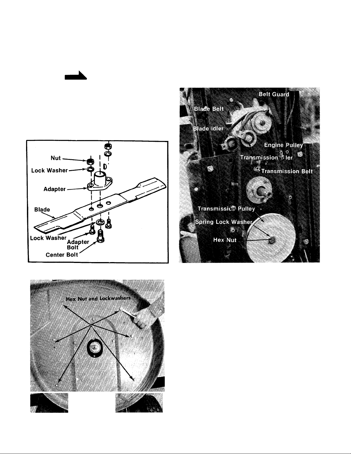
step 2. Remove the blade by removing the hex
head cap screw in the center of the blade.
Hold the blade with one hand and using a
V2" open end, box or adjustable wrench,
remove the bolt. See figure 22.
note
Wrap a rag around the blade to pro
tect your hand.
Step 3. Take off the deck by removing the six hex
nuts and lock washers as shown in figure
23.
Step 4. Remove the transmission belt from the
engine pulley. It may be necessary to
spring the belt guard out of the way. When
installing the new belt be sure to put the
belt guard back in the original position.
See figure 24.
FIGURE 22. BLADE REMOVAL
FIGURE 23. REMOVING THE DECK
FIGURE 24. BELT SYSTEM
Step 5. Remove the belt from the transmission
idler. See figure 25.
Step 6. Remove hex nut and spring lock washer
on the transmission pulley and slide the
pulley out until the belt can be removed.
See figure 24.
Step 7. Replace belt and reassemble.
BLADE BELT REPLACEMENT
Step 1. Lift the front end of the rider up so it rests
on the rear wheels and seat. Block the
mower under the steering wheel to help
support the mower.
Step 2. Remove the blade by removing the hex
head cap screw in the center of the blade.
Hold the blade with one hand and using a
1/2" open end, box or adjustable wrench,
remove the bolt. See figure 22.
12
Page 13
NOTE
NOTE
Wrap a rag around the blade to pro
tect your hand.
Step 3. Take off the deck by removing the six hex
nuts and lock washers as shown in figure
23.
Step 4. Remove the transmission beit from the
engine pulley. See figure 24.
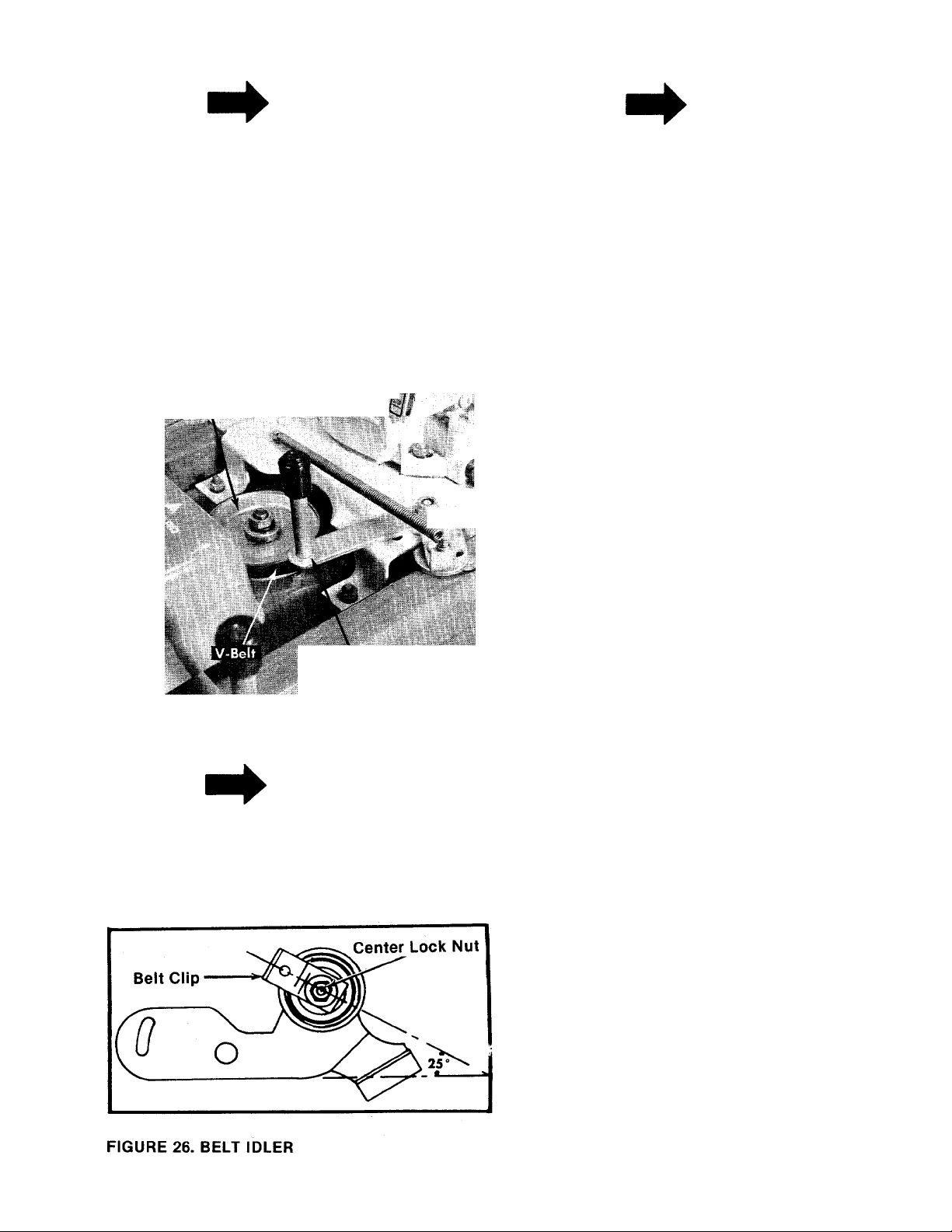
Step 5. Piace the blade engagement iever in tne
engaged position (see figure 25) and
loosen the center lock nut on the blade
idler. See figure 26.
Pulley .
>4 BELT TROUBLE SHOOTING
Blade Engagement Lever
(Shown Disengage4[
FIGURE 25. BLADE ENGAGEMENT LEVER
NOTE
It may be necessary to spring the
belt guard out of the way. When in
stalling the new belt be sure to put
the belt guard back in the original
position. See figure 24.
Use a V z" open end wrench. When
installing the new belt be sure the
belt clip is in the same position as
shown in figure 26.
Step 6. With the blade engagement lever in the
disengaged position, remove the blade
belt from the engine pulley.
Step 7. Remove the belt guard on the blade spin
dle pulley. Unhook the belt from the
pulley.
Step 8. Pull the belt through from the bottom
side. Move the blade engagement lever
between the engaged position and the
disengaged position as you remove the
belt.
Step 9. Install the new belt and reassemble.
CREEPING OR BELT WEAR. See figure 24.
The position of the belt clip on the idler bracket
assembly is important for proper operation of your
mower. Improper position of the belt clip can
cause damage to the belt or it can allow the
mower to “creep” when the clutch pedal is not
depressed. Proper positioning will not allow the
belt clip to touch the belt when the belt is tighten
ed. It also “traps” the belt away from the engine
pulley when the belt is loose. The drawing at left
shows the correct position for the belt clip. Ad
justment is made by loosening the hex nut, ad
justing belt clip to position shown and retighten
ing hex nut securely.
BELT WEAR— Pulleys
For proper belt wear, all pulleys, including the
idler pulley, must be on the same plane. Improper
alignment wiil cause rapid belt wear.
DRIVE PULLEYS. See figure 24.
Alignment may be made by removing the deck.
Check aiignment with a straight edge. The
transmission pulley is held in place with a hex nut
and lock washer. It should not need adjustment.
The engine puiley is heid in position by a hex head
bolt and washers. The idler bracket assembly is
held in position by a shoulder bolt. If realignment
is needed, it is necessary to bend bracket up or
down as alignment requires. Care must be taken
not to damage the belt clip.
13
Page 14

BLADE PULLEYS
Raise front of mower approximately a foot off the
ground and support it with blocks. Sight down
blade belt from front of mower. Note if blade idler
pulley is in line with blade spindle pulley and top
section of engine pulley. If alignment is
necessary, bend idler bracket assembly up or
down as needed. Do not damage or bend belt clip
on idler bracket assembly.
BELT WEAR—Belt Guards and Clips. See figure
24.
Belt guards and clips if improperly positioned will
cause premature belt wear. All belt guards and
clips must completely clear the belt when the belt
is tightened. They should also assist in freeing the
belt from the engine pulley when the belt is loose.
The belt clip on the blade idler bracket assembly
may be checked by removing the top belt guard.
Observe belt and pulley action while'operating the
blade disengage lever. The belt clip on the drive
idler bracket assembly may be checked by remov
ing the inspection plate under the deck. Observe
belt and pulley action while operating the clutch
pedal.
I WARNING I
Do not drain fuel while smoking or if
near an open fire.
Step 2. Drain all the oil from the crankcase (this
should be done after the engine has been
operated and is still warm) and refill the
crankcase with clean new oil.
Step 3. Disconnect the spark plug wire and
remove the spark plug from the cylinder.
Pour about six drops of engine oil into the
cylinder, and then pull the recoil starter
several times to spread the oil on the
cylinder wall. Replace the spark plug, but
DO NOT connect the wire.
Step 4. Clean the engine and the entire mower
thoroughly.
Step 5. Lubricate all lubrication points indicated
in figure 19; then wipe the entire machine
with an oiled rag in order to protect the
surfaces.
CREEPING. See figure 24.
“Creeping” may be caused if the idler bracket
assembly does not move all the way back when
the clutch pedal is released. This may be caused
by insufficient spring pressure, a bent clutch con
trol rod or a binding idler bracket. Check by remov
ing the inspection plate under deck. Observe idler
pulley action while operating the clutch pedal. If
idler bracket binds, lubricate with an all purpose
grease.
NOTE
To insure safe operation of your
unit, ALL nuts and bolts must be
checked periodically for correct
tightness.
OFF SEASON STORAGE
If the machine is to be inoperative for a period
longer than 30 days, the following precautions are
recommended:
Step 1. Working outdoors, run the engine until all
the fuel is consumed. Use a clean dry
cloth to absorb the small amount of fuel
remaining in the tank.
GRASS CATCHER Model No. 190-015A is
available as optional equipment for the mowers
shown in this manual.
I WARNING \
The mower should not be operated
without the entire grass catcher or
chute deflector in place.
NOTE
Under normal usage bag material is
subject to wear, and should be
checked periodically. Be sure any
replacement bag complies with the
mower manufacturer’s recommen
dations.
For replacement bags, use only fac
tory authorized replacement bag.
No. 764-0121.
The manufacturer DCES NCT recommend the use
of any accessory on these riding mowers other
than those manufactured by MTD Products Inc.
14
Page 15

TROUBLE
TROUBLE SHOOTING CHART FOR RECOIL START MODELS
CAUTION; ALWAYS DISCONNECT SPARK PLUG BEFORE ATTEMPTING ANY REMEDY.
LOOK FOR
REMEDY
Engine will not
start when re
coil handle is
pulled.
Engine stops
when the mow
er blade is en
gaged or the
clutch is re
leased.
Engine
smokes.
Excessive
vibration
Mower will
not discharge
grass or leaves
uncut strips.
Clutch and blade
not disengaged.
Ignition key not
in the ON position.
Throttle not in the
starting position.
No spark to spark plug. Spark plug lead disconnected. Connect lead.
No fuel to the carbure
tor.
Air filter dirty.
Mechanical failure
(wires or switch).
Clutch pedal must be depressed and blade must be shut off.
Turn on the ignition key.
Check owner’s guide for correct position for throttle control for starting.
Hold spark plug lead away from engine block about 1/8". Crank engine. There should be a
spark. If not, have the engine repaired at authorized engine service dealer.
Faulty spark plug. To test, remove spark plug. Attach spark plug lead to spark plug. Ground
spark plug body against the engine block. Crank the engine. The spark plug should fire at the
electrode. Replace if it does not.
Gasoline tank empty. Fill.
Fuel valve shut off. Open valve. Valve is located either at the bottom of the fuel tank or on the
carburetor.
Fuel line is plugged. Remove and clean.
If the air cleaner is dirty, the engine may not start. Clean or replace as recommended by the en
gine manufacturer.
The interlock system includes two mechanical activated switches which are wired in parallel. If
the buttons on both switches are not depressed at least 1/8", the magneto will be grounded
and the engine will not start. While testing the interlock system, you will make the mower
temporarily unsafe by permitting the engine to be started with the blade and clutch engaged.
WARNING: While testing, disengage the clutch, shut off the blade control, set the parking
brake and place the gear shift lever in neutral. Disconnect the yellow wire where it attaches to
the primary wire from the breaker assembly on the engine. Try to start the engine. If the engine
does not start, the problem is in the engine (e.g. no fuel or no ignition). If the engine does start,
the problem is in the safety system. Check the following: 1. The interlock wire may be ground
ed by being pinched or rubbing through the insulation. Tape or replace the wire. 2. The bolt on
the flat spring behind the recoil starter where the yellow wire attaches must be insulated from
the spring. Use a continuity tester. If it is not insulated, remove the bolt and nut, and replace
the two fiber washers and reassemble.
Recoil handle is not
in proper position.
Engine loses crankcase
vacuum.
Bent or damaged blade
spindle
Bent blade. Stop engine immediately. Replace damaged blade. Only use original equipment blades.
Engine speed too low.
Transmission selection.
Blades short or dull.
After the engine starts, the recoil starter handle must be pushed into the dashboard and turned
a quarter turn either direction to lock it in place.
Dipstick not seated or broken. Replace defective part.
Engine breather defective. Replace.
Stop engine immediately. Check all pulleys, blade spindles, blade adapters, keys and bolts for
tightness or damage.
Tighten or replace any damaged parts.
Throttle must be set between 3/4 and full throttle.
Use lower transmission gear. The slower your ground speed, the better the quality of cut.
Sharpen or replace blades (uncut strip problem only).
15
Page 16
130-360A
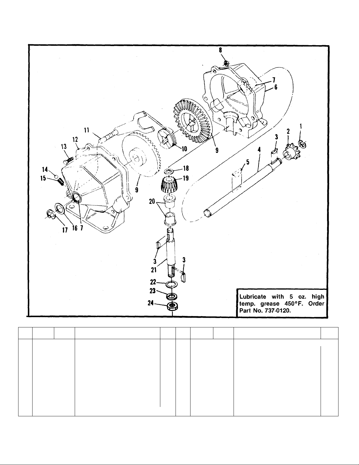
SINGLE SPEED TRANSMISSION PART NO. 717-0223
REF.
NO.
10
11
12 717-0124
PART
COLOR
NO.
1 716-0104
2 748-0852
714-0129
3
4 711-0854
714-0126
5
717-0123
6
7
748-0855
712-0117
8
9 748-0856
CODE
DESCRIPTION
Snap Ring
Sprocket 8T #41
Key Hi-Pro #4
Shaft Output
Key Hi-Pro #606 (Hardened)
Housing Half
Bearing
Lock Nut V4-28 Thd.*
Bevel Gear
748-0857 Clutch Collar
08583
Detent Shaft Ass’y.
Housing Half w/Detent Hole
‘For faster service obtain standard nuts, bolts and washers
locally. If these items cannot be obtained locally, order by
part number and size as shown on parts, list.
NEW
PART
_____
REF.
NO.
PART
NO.
COLOR
CODE
DESCRIPTION
13 710-0195 Hex Hd. Cap Scr. V4-28 x .62*
14
741-0862 Detent Ball
15
732-0863
16 736-0116
Detent Spring
Washer
17 716-0106 E-Ring
18 716-0865 Snap Ring #3100-50
19 748-0866
748-0867 Bearing
20
21 738-0159
Bevel Pinion
Pinion Shaft
22 736-0192 Washer
736-0921 Lock Washer Vz "*
23
24 712-0922 Hex Jam Nut V2-20 Thd.*
16
NEW
PART
Page 17
130-360A
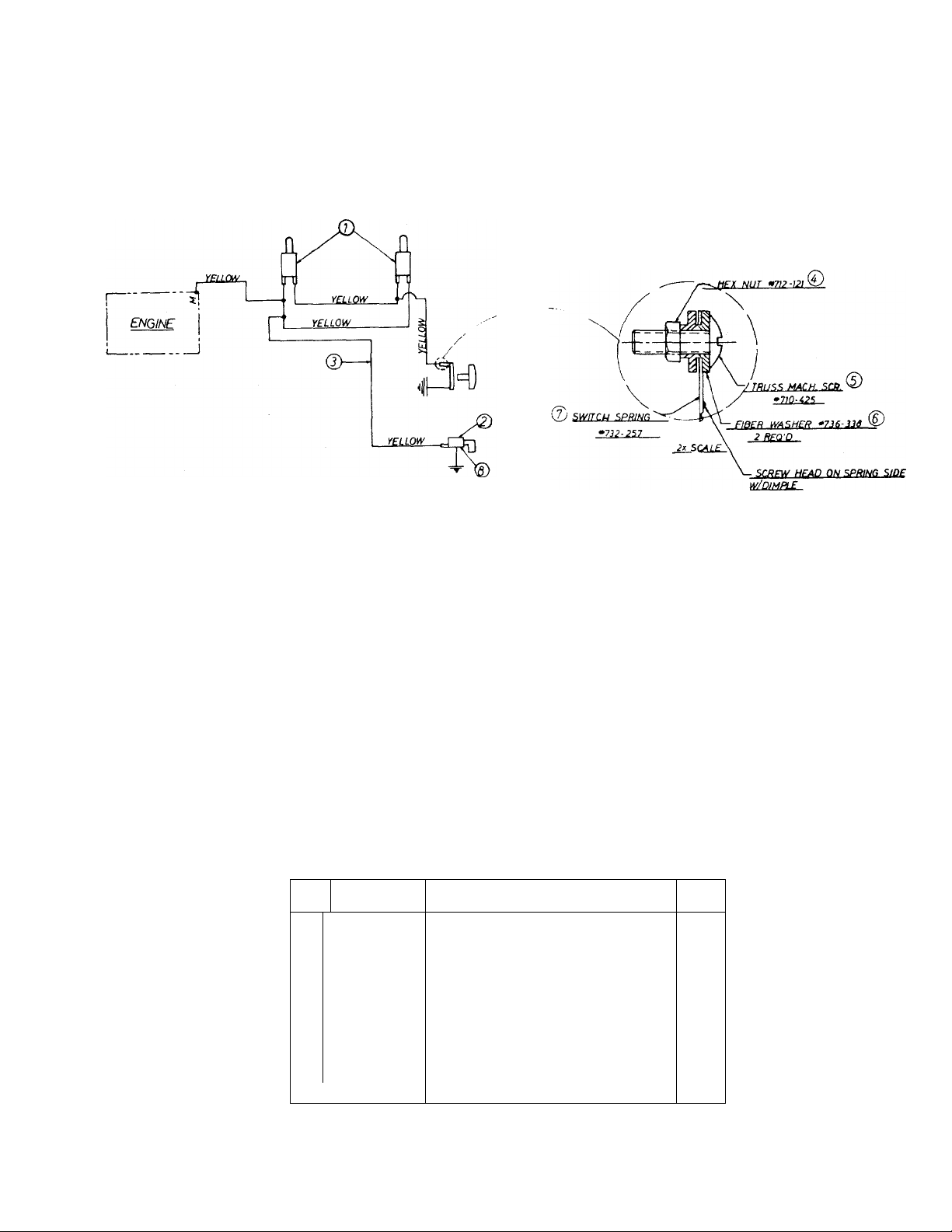
RECOIL WIRING
PARTS LIST FOR WIRING
REF.
NO.
1 725-0269 Safety Switch—Red
PART
NO.
DESCRIPTION
(2 Req’d.)
725-0464
2
Magneto Ignition Switch
w/Nut
725-0201
3 725-0273
Ignition Key
Wire Harness
4 712-0121 Hex Nut #10-24
5 710-0425 Truss Mach. Scr. #10-24. x .62
736-0338
6
7 732-0257
8 736-0225
Fiber Washer (2 Req’d.)
Switch Spring
Internal L-Wash. 5/8 I.D.
17
NEW
PART
Page 18
130-360A
!!0 109
IF YOU WRITE TO US ABOUT THIS ARTICLE
OR IF YOU ORDER REPLACEMENT PARTS AL
WAYS MENTION THIS MODEL & SERIAL NO
MODEL
NOTE
This instruction manual covers various
models and all specifications shown do not
necessarily apply to your model. Specifica
tions subject to change without notice or
obligation.
18
Page 19

: PART
REF
NO
757-0265
1
731-0348
2
3
07800
736-0119
4
712-0267
5
6 12829
NO.
COLOR
CODE
—462
—462
DESCRIPTION
Seat
Rear Cover
Frame—Rear
L-Wash. 5/16" Scr.*
Hex Nut 5/16-18 Thd.*
Seat Support Brkt. Ass’y.—
L.H.
712-0267
7
712-0429
8
736-0264
9
710-0198
10
717-0273
11
09055
12
747-0110
13
711-0152
14
732-0118
15
712-0107
16
712-0116
17
710-0938
18
Hex Nut 5/16-18 Thd.*
Hex Ins. L-Nut 5/16-18 Thd.
FI-Wash. .344 l.D. x .62 O.D.
Hex Scr. 5/16-18 x .75" Lg.*
Rear Axle Ass’y.
Brake Cup
Brake Rod
Adjustment Link (Brake Band)
Ext. Spring (Brake Return)
Hex Cent. L-Nut V4-20 Thd.
Hex Ins. L-Nut 3/8-24 Thd.
Set Scr. 1/4-28 X .25" Lg.
(Cup Point)
711-0139
19
11590
20
710-0152
21
712-0267
22
712-0267
23
08551
24
25 07794
26 07792
27 748-0391
734-0522
28
—462
—462
—462
Collar 3/4" l.D.
Support Adj. Wheel Hanger
Hex Scr. 3/8-24 x 1.00" Lg.*
Hex Nut 5/16-18 Thd.*
Hex Nut 5/16-18 Thd.*
Brake Band Ass’y.—Comp.
Wheel Adjustment Hanger
Bearing Plate
Spherical Bearing .753 l.D.
Rear Wheel Ass’y.—Comp.
12.2 X 3.7
734-0517
29
Rear Wheel Rim Ass’y.
(Includes Hub)
734-0301
Rear Wheel Tire Only 12.2 x
3.7
736-0242 Belleville Wash. .343 l.D. x
30
.875 O.D.
710-0627
31
Hex Scr. w/Lock 5/16-24 x
.75" Lg.
736-0134
32
717-0273
33
712-0429
34
736-0300
35
712-0107
36
37 736-0329
07364
38
713-0723
39
40 08720
41 720-0143
732-0260
42
43 11249
44 11563
726-0121
45
738-0140
46
47 714-0507
—462
Fi-Wash.
Rear Axle Ass’y.
Hex Ins. L-Nut 5/16-18 Thd.
FI-Wash. .385 l.D. x .87 O.D.
Hex Oent. L-Nut V4-20 Thd.
L-Wash. 1/4" Scr.*
Shift Lever Brkt. Ass’y.
#41 Master Link
Transmission Shift Lever
Grip
Brake Tension Spring
Knob
Clutch Lever—L.H.
Push Cap 1/4" Dia.—Black
Shid. Scr. .437 Dia. x .180
Cotter Pin 3/32" Dia. x .75"
Lg.*
710-0427
48
49 11556
50 11581
714-0115
51
—462
Hex Scr. 3/8-16 X 2.00" Lg.*
Clutch Pedal Ass’y.
Side Channel Ass’y.—L.H.
Cotter Pin 1/8" Dia. x 1.00"
Lg.*
52 09335
736-0116
53
711-0197
54
712-0711
55
711-0198
56
57 08712
712-0267
58
—462
Wheel Brkt. Ass’y.—L.H.
FI-Wash. .635 l.D. x .93 O.D.
Tie Rod
Hex Jam Nut 3/8-24 Thd.
Pivot Bushing (Tie Rod End)
Steering Post Ass’y.
Hex Nut 5/16-18 Thd.*
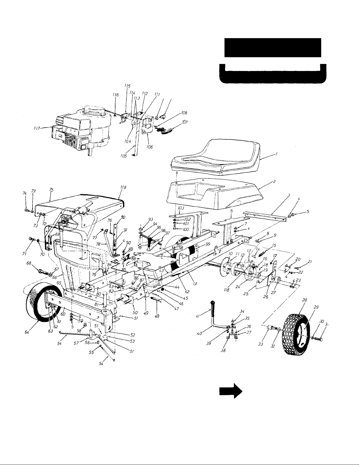
PARTS LIST FOR MODEL 130-360A
NEW
PART
PART
NO.
COLOR
CODE
REF.
NO.
07386 FI-Wash. .390 l.D. x 1.75" O.D.
59
07865 —462 Support Bar Ass’y.—Front
60
712-0137 L-Nut 7/16-20 Thd.
61
62 736-0156 FI-Wash. .635" l.D. x 1.20"
63 09336 —462 Wheel Brkt. Ass’y.—R.H.
64
734-0510
08487
65
66 08718
—462
—462 Grille
67 736-0116 FI-Wash. .635 l.D. x .93 O.D.
68 738-0186 ShId. Bolt .625" Dia. x 2.75
69 710-0190
736-0142 FI-Wash. .281 l.D. x .50" O.D.
70
71 710-0179 Hex F-Tapp Scr. V4-20 x .50"
72 712-0287 Hex Nut V4-20 Thd. *
73 736-0329
74
710-0258
12832
75
76
710-0606
—462
77 712-0107
08715 Steering Frame Support
78
11553 Brake Pedal Axle Ass’y.
79
11582
80
711-0577 Clevis Pin 5/8" Dia. x 3.06" Lg
81
08164
82
—462 Side Channel Ass’y.—R.H.
83 712-0130
11564 Brake Lever—R.H.
84
85 710-0258
86 715-0249 Spring Pin Spiral 5/32" Dia.
87
11558 Brake Lever Brkt. Ass’y.
88 725-0269 Safety Switch
89 736-0329
90 712-0287 Hex Nut 1/4-20 Thd.*
91 710-0176 Hex Scr. 5/16-18 x 2.75" Lg.*
92 08865 Hood Support Brkt. —Front
93 712-0130 Hex Ins. L-Nut 3/8-16 Thd.
94
736-0300 FI-Wash. .385 l.D. x .87 O.D.
95 732-0158 Blade Tension Spring
96 720-0143 Grip (For Blade Lever)
97 07898
98
710-0176 Hex Scr. 5/16-18 x 2.75" Lg.
07792
99
—462
100 710-0258 Hex Scr. 1/4-20 X .62" Lg.*
101 736-0329
102 736-0142 FI-Wash. .281 l.D. x .50
103 12828 —462
104 732-0257 Switch Spring
08865
105
106 11561
107 11263
108
710-0351
109 725-0128 Ignition Key
110 736-0225 Internal L-Wash. 5/8" l.D.
111 710-0425 Truss Mach. Scr. #10-24 x
112
725-0464 Ignition Switch
113 736-0338 Fiber Washer
114
712-0121 Hex Nut #10-24 Thd.*
115 11053
116 712-0147
117
— Engine
118 08109 Pivot Lever
119
731-0130
DESCRIPTION
O.D.
Front Wheel Ass’y.—Comp.
Front Channel Ass’y.
Hex Scr. 5/16-18 x 4.00" Lg.*
Lg.*
L-Wash. 1/4" Scr.*
Hex Scr. 1/4-20 X .62" Lg.*
Front Hood
Hex Scr. 1/4-20 X 1.50" Lg.*
Hex Cent. L-Nut 1/4-20 Thd.
Heat Shield
Hex Ins. L-Nut 3/8-16 Thd.
Hex Scr. 1/4-20 X .62" Lg.*
X 1.12" Lg.
L-Wash. 1/4" Scr.*
Blade Tension Brkt. Ass’y.
Bearing Plate
L-Wash. 1/4" Scr.*
O.D. X .063
Seat Support Brkt. Ass’y.—
R.H.
Hood Support Brkt. —Front
Starter Brkt.
Plastic Handle (Starter Rope)
Truss Mach. Scr. #10 x .50"
Lg.
.62" Lg.
Switch Brkt. Ass’y.
Speed Nut #10-24 U-Type
Ext. U-Channel Vinyl 22.5" Lg
"NEW
PART
Page 20
co
co
■
о
co
о
CM
Page 21

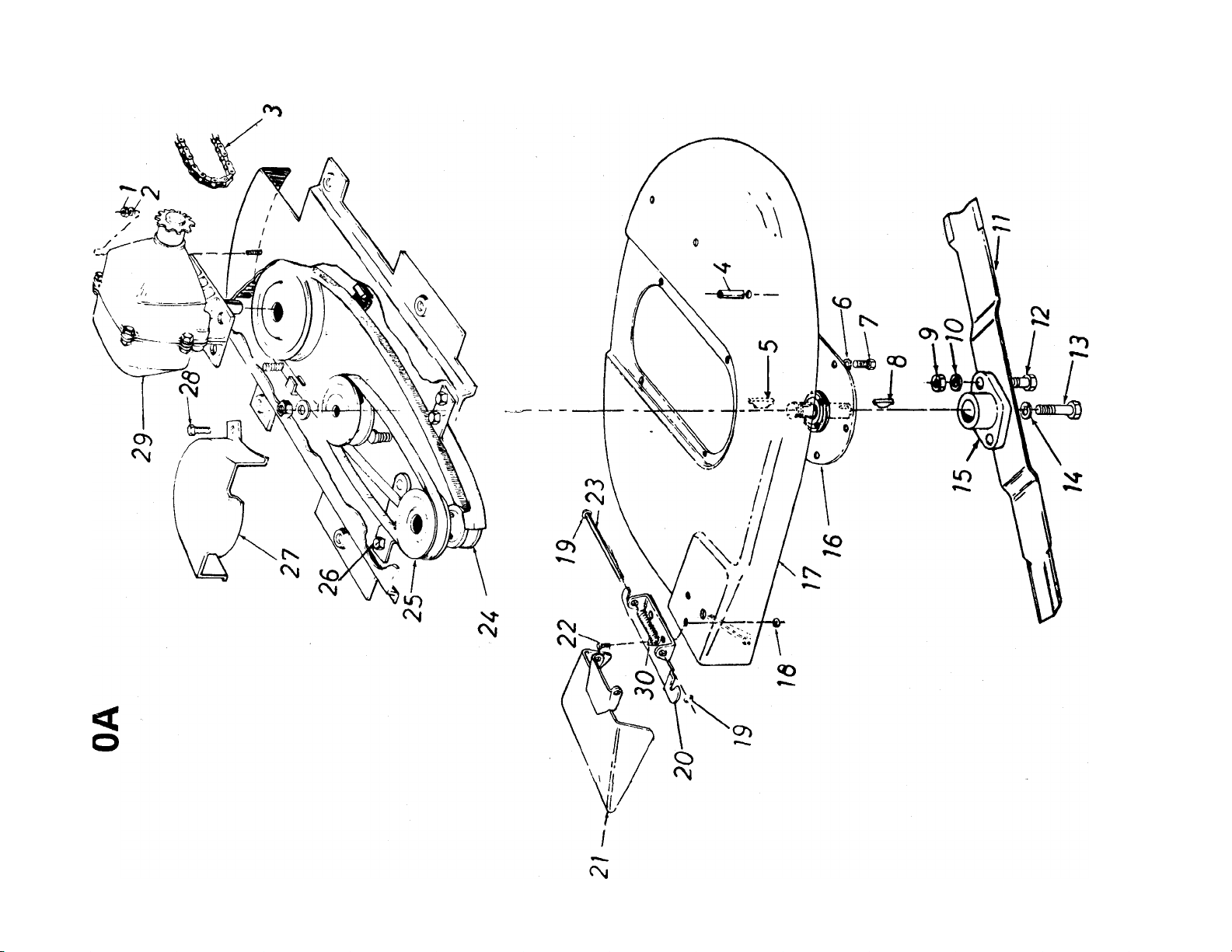
PARTS LIST FOR MODEL 130-360A
REF.
NO.
PART
COLOR
NO.
CODE
1
712-0267 Hex Nut 5/16-18 Thd.‘
2
736-0119
3 713-0357
Spring L-Washer 5/16" Scr.*
#41 Chain 1/2" Pitch x 67
DESCRIPTION
Links
4507956
Spacer (Between Deck and
Frame)
714-0365
736-0607
6
7
710-0107
8 714-0365
9 712-0123
10
736-0119
11
742-0132 Blade
#6 Hi-Pro-Key 5/32 x 5/8" Dia.
External L-Washer 5/16" Scr.*
Hex Scr. 5/16-24 x .50" Lg.*
#6 Hi-Pro-Key 5/32 x 5/8" Dia.
Hex Nut 5/16-24 Thd.*
Spring L-Washer 5/16" Scr.*
12 710-0117 Hex Scr. 5/16-24 x 1.00"
Lg.-H.T.
13 710-0459
Hex Scr. 3/8-24 x 1.50" Lg.—
H.T.
14 736-0217
Spring Lock Washer 3/8"
Scr.—H.D.
15
16
17
10769
09387
11595
—452
Blade Adapter Kit
Inspection Plate
Deck Ass’y —Comp.
18 712-0107 Hex Center L-Nut V4-20 Thd.
19 726-0106
20 11399
21
11633 —462 Chute Deflector Ass’y.—
—462 Adapter Plate Ass’y.
Push Nut 1/4" Rod
Comp.
22
710-0230
Hex Scr. 1/4-28 x .50" Lg.*
23 711-0571 Pivot Pin
24
754-0936
25 756-0181
“V”-Belt 1/2" X 47" Lg.
Two-Step Engine Pulley
26 712-0130 Hex Inserted L-Nut 3/8-16
27 07397 —462 Belt Cover
28 710-0128 Hex F-Tapp. Scr. #10-32 x
.50" Lg.*
29 717-0223
30
732-0261
Transmission Ass’y.—Comp.
Torsion Spring
NEW
PART
*For faster service obtain standard nuts, bolts and washers
locally. If these items cannot be obtained locally, order by
part number and size as shown on parts list.
(462—Red Flake)
When ordering parts, if color or finish is important, use the
appropriate color code shown at left. (e.g. Red Flake Finish
(462).)
The engine is not under warranty by the mower manufacturer. If repairs or service is needed on the
engine, please contact your nearest authorized engine service outlet. Check the “Yellow Pages” of
your telephone book under “Engines — Gasoline.”
21
Find It Fast
In The
Yellow Pages
Page 22
130-360A
Engine
Transmission ]Q
22
Page 23

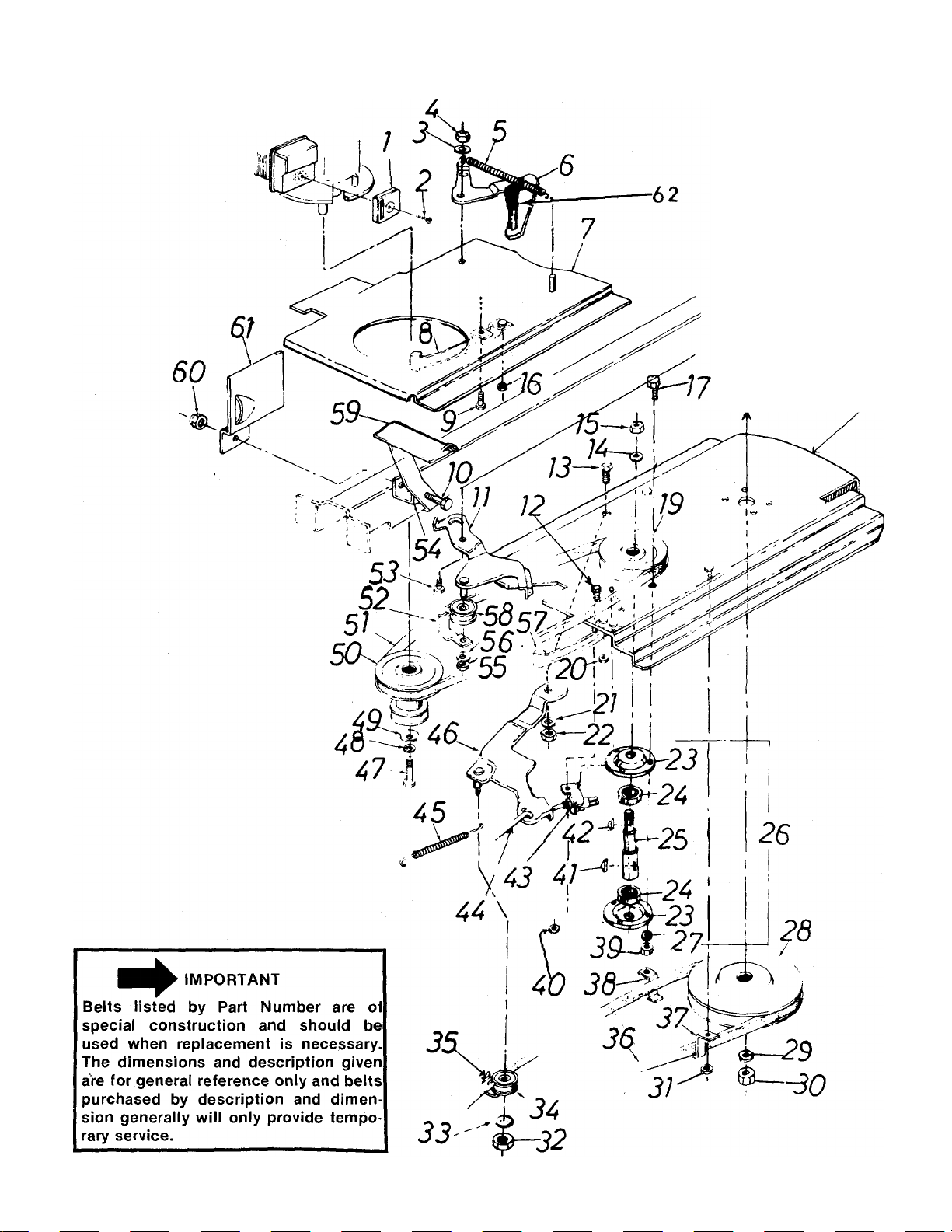
PARTS LIST FOR MODEL 130-360A
PART
^REF.
NO.
1
09296
2 69338
3 736-0300
4
712-0130
5
732-0158
6
07898
7 11584
8 07401-1
9 710-0258
NO.
COLOR
CODE
DESCRIPTION
Exhaust Deflector
Screw
FI-Wash. .385 I.D. x .87 O.D.
Hex Ins. Lock Nut 3/8-16 Thd.
Blade Tension Spring
Blade Tension Brkt. Ass ’y .
Engine Mtg. Plate Ass’y-
Belt Guard
Hex Hd. Cap Scr. V4-20 x
.62" Lg.*
10 710-0427
Hex Hd. Cap Scr. 3/8-16 x 41 714-0365 #6 Hi-Pro Key 5/32 x 5/8" Dia.
2.00" Lg.*
11 11588
12
710-0258
Blade Idler Brkt. Ass’y. 43 725-0269 Safety Switch
Hex Hd. Cap Scr. V4-20 x
.62" Lg.*
13 738-0140
14 736-0921
15 712-0200
712-0287
16
Shid. Scr. .437" Dia. x .180
Spring Lock Washer Vz" Scr
Hex Ins. Lock Nut V2-2O Thd.
Hex Nut 1/4-20 Thd.*
17 710-0322 Hex Sems Scr. 5/16-18 x
1.00" Lg.* Scr. H.D.
18 11586
19 09925
Blade Mtg. Plate Ass’y.
Pulley 4" Dia. (For Blade
Spindle)
712-0287 Hex Nut 1/4-20 Thd.*
20
21
22
736-0300
712-0158
FI-Wash. .406 I.D. x .734 O.D.
Hex Center Lock Nut 5/16-18
Thd.
23 08253
24
741-0919
25 738-0188
26
741-0168
27
736-0119
Bearing Housing
Ball Bearing
Blade Spindle
Blade Spindle Ass’y.—Comp.
Spring Lock Washer 5/16"
Scr.*
28 756-0175
Pulley 7" Dia. x 1/2" I.D.
(Transmission)
29 736-0921
30 712-0200
Spring Lock Washer 1/2" Scr
Hex Jam Nut 1/2-2O Thd.* |
NEW
PART
*
*
REF.
NO.
31 712-0123
32 712-0116
33
PART
NO.
COLOR
CODE
DESCRIPTION
Hex Nut 5/16-24 Thd.*
Hex Ins. Lock Nut 3/8-24 Thd
736-0160 FI-Wash.
34 756-0370 Idler Bearing Ass’y.
07353 Belt Clip
35
36 754-0936 “V”-Belt 1/2" X 47" Lg.
07437 Belt Clip
37
38
39
40
07437
712-0267
712-0287
Belt Clip
Hex Nut 5/16-18 Thd.*
Hex Nut 1/4-20 Thd.*
42 714-0365 #6 Hi-Pro Key 5/32 x 5/8" Dia.
44 11562 Transmission Link
45 732-0121 Idler Extension Soring
46 11551
Transmission Idler Brkt.
Ass’y.
47
710-0152
Hex Hd. Cap Scr. 3/8-24 x
1.00" Lg.*
736-0217 Spring Lock Washer 3/8"
48
49
736-0219
Belleville Washer .400 I.D. x
1.120 O.D.
756-0181
50
754-0107
51
52 07353
738-0143
53
07787
54
712-0216
55
Two Step Engine Pulley
“V”-Belt 1/2" X 30" Lg.
Belt Clip
ShId. Scr. .498 Dia. x .340
Spacer Bracket
Hex Inserted Lock Nut 3/8-24
Thd.
736-0160
56
57
07400-1
756-0370
58
59 11556
712-0130
60
FI-Wash.
Belt Guard
Idler Bearing Ass’y.
Clutch Pedal Ass’y.
Hex Inserted Lock Nut
3/8-16 Thd.
61 08164
62 07343
Heat Shield
Cap (For Blade Lever)
NEW
PART
'For faster service obtain standard nuts, bolts and washers locally. If these items cannot be obtained locally, order by part
number and size as shown on parts list.
(462—Red Flake)
The engine is not under warranty by the mower manufacturer. If repairs or service is needed on the
engine, please contact your nearest authorized engine service outlet. Check the “Yellow Pages” of
your telephone book under “Engines — Gasoline.”
When ordering parts if color or finish is important, use color code shown at left. (e.g. Red Flake
Finish—11907 (462).)
Find It Fast
In The
Yellow Pages
23
Page 24
130-360A
24
Page 25
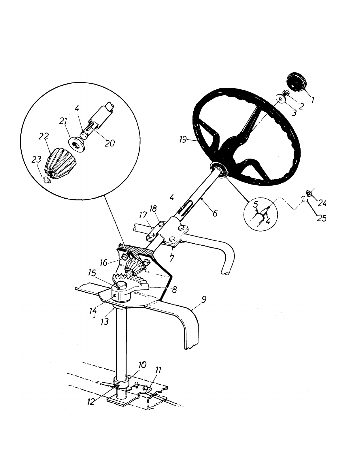
PARTS LIST FOR MODEL 130-360A
PART
REF.
NO.
1 731-0220
2 712-0158
NO.
COLOR
CODE
DESCRIPTION
Steering Wheel Cap
Hex Center Lock Nut 5/16-18
Thd.*
736-0242
3
Belleville Washer .343 I.D. x
.875 O.D.
4 738-0198
748-0184
5
Steering Column Rod
Flange Bearing—.628 I.D. x
1.120 O.D.
6
712-0107
7
11774
Steering Tube Ass’y.
Hex Center Lock Nut V4-20
Thd.
8
9
10
11
12
748-0137
08704
711-0139
08712
710-0938
Gear Segment
Steering Frame Ass’y.
Collar 3/4" I.D.
Steering Post Ass’y.
Set Scr. V4-28 x .25" Lg.—
Cup Point
13 748-0138
14 710-0938
Flange Bearing
Set Scr. 1/4-28 X .25" Lg.
(Cup Point)
15 714-0388
#61 Hi-Pro-Key 3/16 X 5/8"
Dia.
16
710-0198
Hex Sems Scr. 5/16-18 x .75"
Lg.‘
17
18
08714
710-0258
Tube Clamp
Hex Hd. Cap Scr. V4-20 x
.62" Lg.*
19 731-0219
714-0129
20
Steering Wheel
#4 Hi-Pro-Key 3/32 x 5/8"
Dia.—Hardened
21
748-0108
Flange Bearing Vz" Bore
Bronze
22 748-0866
23 726-0221
736-0174 Wave Washer—.660 I.D. x .88
24
Pinion Gear
Push Cap—.500 Dia. Shaft
O.D. X .010
25
736-0156
FI-Wash.
NEW
PART
*For faster service obtain standard nuts, bolts and washers
locally. If these items cannot be obtained locally, order by
part number and size as shown on parts list.
(462—Red Flake)
When ordering parts, if color or finish is important, use the
appropriate color code shown at left. (e.g. Red Flake Finish
(462).)
WHEEL CHART
FRONT WHEEL
PART
NO.
734-0510
748-0146
DESCRIPTION
Wheel Ass’y. Comp. 10.25 x 3.25
Flange Bearing w/Flats .630" I.D.
734-0522
734-0517
734-0301
734-0255
734-0336
25
PART
NO.
NOTE: The engine is not under warranty by
the mower manufacturer ... If repairs or
service is needed on the engine, please
contact your nearest author
ized engine service outlet. Find It Fast
Check the “Yellow Pages” of In The
your telephone book under Y^ow Pages
“Engines—Gasoline.”
REAR WHEEL
DESCRIPTION
Wheel Ass’y. Comp. 12.2 x 3.7
Rim Ass’y.w/Hub
Tire Only Tubeless 12.2 x 3.7
Air Valve
Inner Tube (Service Only)
Page 26

PARTS INFORMATION
POWER EQUIPMENT PARTS AND SERVICE
Parts and service for all MTD manufactured pov^er equipment are
available through the authorized service firms listed below. All orders
should specify the model number of your unit, parts number,
description of parts and the quantity of each part required.
ALABAMA BIRMINGHAM
Auto Electric & Carburetor Co
ARKANSAS FORT SMITH
Mity Mite Motors, Inc..
Sutton’s Lawn MowerShop
CALIFORNIA PORTERVILLE
Billious......................................................................75 North D Street.... 93257
Lawn Mower Supply Co
J.W. Jewett Co...................................................981 Folsom St......................................94107
COLORADO DENVER
South Denver Lawn Equip.......................................527 West Evans........................ 80223
FLORIDA JACKSONVILLE
Radco Distributors........................ ..............................2403 Market St.........................32206
Small Eng. Dist.........................................................2351 N.W. 147th St.... 33054
GEORGIA EAST POINT
East Point Cycle & Key
ILLINOIS LYONS
Keen Edge Co
.............................................................
INDIANA ELKHART
Parts & Sales Inc......................................................2101 Industrial Pkwy.. 46514
IOWA DUBUQUE
Power Lawn & Garden Equip..................................2551 J.F. Kennedy— 52001
LOUISIANA NEW ORLEANS
Suhren Engine Co.........................................................8330 Earhart Blvd
MARYLAND ТАКОМА PARK
Center Supply Co...........................................6867 New Hampshire Ave.. 20012
MASSACHUSETTS SPRINGFIELD
Morton B. Collins Co
MICHIGAN LANSING
Lorenz Service Co
Power Equipment Dist
......................................................
MINNESOTA HOPKiNS
Hance Distributing Inc...............................................420 Excelsior Ave. W.. 55343
Power Tools Inc
........................................
MISSISSIPPI BILOXI
Biloxi Sales & Service, Inc
MISSOURI KANSAS CITY
Automotive Equip. Service
Ross-Frazier Supply Co
Henzler, Inc
.................................................................
NEW JERSEY BELLMAWR
Lawnmower Parts Inc................................................717 Creek Rd
Feld Distributor..........................................................28 Glen Rd.................................07070
NEW YORK CARTHAGE
Gamble Dist., Inc.........................................................West End Ave
................................
....................
2625 4th Ave. S.
4515 South 16th Street 72901
NORTH LITTLE ROCK
.....................................
Rt. 4 Box 368
SAN BERNARDINO
..........................................
25608 E. Baseline ... .92410
SAN FRANCISCO
OPA LOCKA
..................................................
8615 Ogden Ave
.................................................
300 Birnie Ave..........................01107
2500 S. Pennsylvania. 48910
MOUNT CLEMENS
.............................................................
ST. PAUL
3771 Sibley Memorial Hwy. . 55122
........................................
........................................
506 Caillavet St
3117 Holmes St
ST. JOSEPH
............................................
8th and Monteray
ST. LOUIS
2015 Lemay Ferry Rd.. 63125
RUTHERFORD
...........................
2834 Church St
.....................
......................
...................
36463 South Gratiot.. 48043
........................
.......................
_________
............................
.........................
.35233
72117
30344
60534
70118
39533
64109
64503
08030
13619
BRIGGS AND STRATTON, TECUMSEH AND PEERLESS PARTS AND
SERVICE
Briggs & Stratton, Tecumseh and Peerless parts and service should be
handled by your nearest authorized engine service firm. Check tf
yellow pages of your telephone directory under the listinj.
Engines—Gasoline, Briggs & Stratton or Tecumseh Lauson.
SYRACUSE
GTP Leisure Products Inc
..................................
420 Marcellus St
....................
NORTH CAROLINA GOLDSBORO
Smith Hardware Co
............................................
515 N. George St
....................
GREENSBORO
Dixie Sales Company
........................................
327 Battleground Ave. 27402
OHIO CARROLL
Stebe’s Mid-State Mower Supply ... Box 366-71 High St. ..
CLEVELAND
Bleckrie, Inc
........................................................
7900 Lorain Ave.....................
WADSWORTH
National Central......................................................................687 Seville Rd
YOUNGSTOWN
Burton Supply Co....................................1301 Logan Ave. Box 929 . .
OKLAHOMA ADA
Ada Auto Supply............................................................301 E. 12th St
..............
MUSKOGEE
Victory Motors, Inc.............................................605 S. Cherokee
.....................
OKLAHOMA CITY
Forest Sales Inc
...................................................
1039 NW 63rd St
...................
OREGON PORTLAND
Kenton Supply Co..
..........................................
8216 N. Denver Ave. ..
PENNSYLVANIA CHESTER
Stull Equipment Corp.........................................742 W. Front St......................
HARRISBURG
EECOInc
............................................................................
4021 N.ethSt.............
PHILADELPHIA
Thompson Rubber Co
........................................
5222-24 N. Fifth St
________
PITTSBURGH
Bluemont Co
.............................................................
11125 Frankstown Rd.
TENNESSEE KNOXVILLE
Master Repair Service
..............................................
2000 Western Ave. ...
MEMPHIS
Memphis Cycle & Supply Co........................................421 Monroe Ave
American Sales & Service, Inc
......................................
1922 Lynnbrook
........
........
TEXAS DALLAS
Marr Brothers, Inc..............................................423 E. Jefferson
.....................
FORT WORTH
Woodson Sales Corp.......................................................1702 N. Sylvania
.........
HOUSTON
Bullard Supply Co...............................................2409 Commerce St....
SAN ANTONIO
Catto & Putty, Inc...............................................414 Live Oak
..........................
UTAH SALT LAKE CITY
A-1 Engine & Mower Co
....................................
437 E. 9th St
...........................
VERMONT BURLINGTON
Vermont Hdwe. Co. Inc......................................180 Flynn Ave
........................
VIRGINIA RICHMOND
RBI Corp
.............................................................
963 Myers St...........................
WASHINGTON SEATTLE
Bailey’s Inc..................................................................1414 14th Ave
...............
WEST VIRGINIA CHARLESTON
Young’s, Inc.............................................................233 Virginia St., E............
WISCONSIN APPLETON
Automotive Supply Co
........................................
123 S. Linwood Ave...
13204
27530
43112
44102
.
44281
44501
74820
74401
73116
97217
19013
17110
19120
15235
37921
,38103
38116
75203
76111
77003
78298
84111
05401
23260
98102
25301
54911
WARRANTY PARTS AND SERVICE POLICY
The purpose of warranty is to protect the customer from defects in workmanship and materials, defects which are NOT detected ot the time of
manufacture. It does not provide for the unlimited and unrestricted replacement of parts. Use and maintenance are the responsibility of the
customer. The manufacturer cannot assume responsibility for conditions which it has no control. Simply put, if it's the manufacturer’s fault, it’s
the manufacturer's responsibility; if it's the customer's fault, it's the customer's responsiblity.
CLAIMS AGAINST THE MANUFACTURER’S
WARRANTY INCLUDES
1. Replacement of Missing Parts on new equipment.
2. Replacement of Defective Parts within the warranty period.
3. Repair of Defects within the warranty period.
All claims MUST be substantiated with the following information:
1. Model Number of unit involved.
2. Date unit was purchased or first put into service.
3. Date of failure.
4. Nature of failure.
MTD PRODUCTS INC • 5965 GRAFTON ROAD • P.O. BOX 36900 • CLEVELAND OHIO 44136
 Loading...