

Page 1
7170.2
July 2000
Replaces 7170.1
All belt drive models (except 575V) are
Underwriter’s Laboratories, Inc. listed.
Belt Drive Fluid Coolers
Belt Drive Fluid Coolers
Model BFF
Model BFF
Specification Data
Specification Data
Page 2
BOHN DIRECT DRIVE FLUID COOLERS
BOHN DIRECT DRIVE FLUID COOLERS
Belt Drive Fluid Coolers
Multiple fans, carefully matched to the coil surface cover a large
percentage of the face area providing uniform air distribution.
Energy efficient, three phase 1750 RPM motors with drip-proof,
grease lubricated ball bearings. Each motor is inherently
overcurrent protected providing built-in protection against single
phasing. All motors are factory wired with leads marked and
terminated in a single weatherproof junction box on outside of
the unit casing.
Convenient access panels are provided on each fan section for
ease in maintaining fans.
Casing is constructed of heavy gauge aluminum, or galvanized
steel.
Multiple fan sections, each powered by a separate motors, are
separated by a full width baffle to prevent air bypass during fan
cycling.
Motors are positioned within unit casing for weather protection.
Adjustable base provides ease in belt tension adjustment.
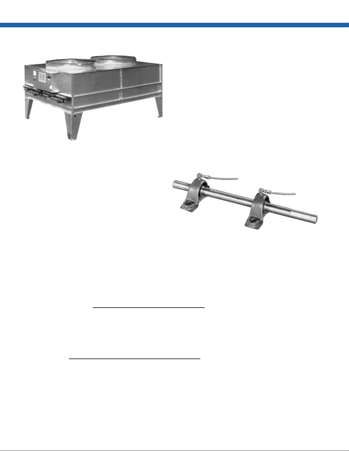
Each fan is equipped with heavy duty pillow block ball bearings.
Bearings are supplied with lubrication fittings shown. Fan shafts
are polished steel, precision machined to assure smooth
operation, minimum bearing wear. Shafts are coated with a
corrosion resistant dressing.
Fan guards are constructed of heavy gauge, close meshed, steel
wire zinc plated and iridite dipped to minimize corrosion.
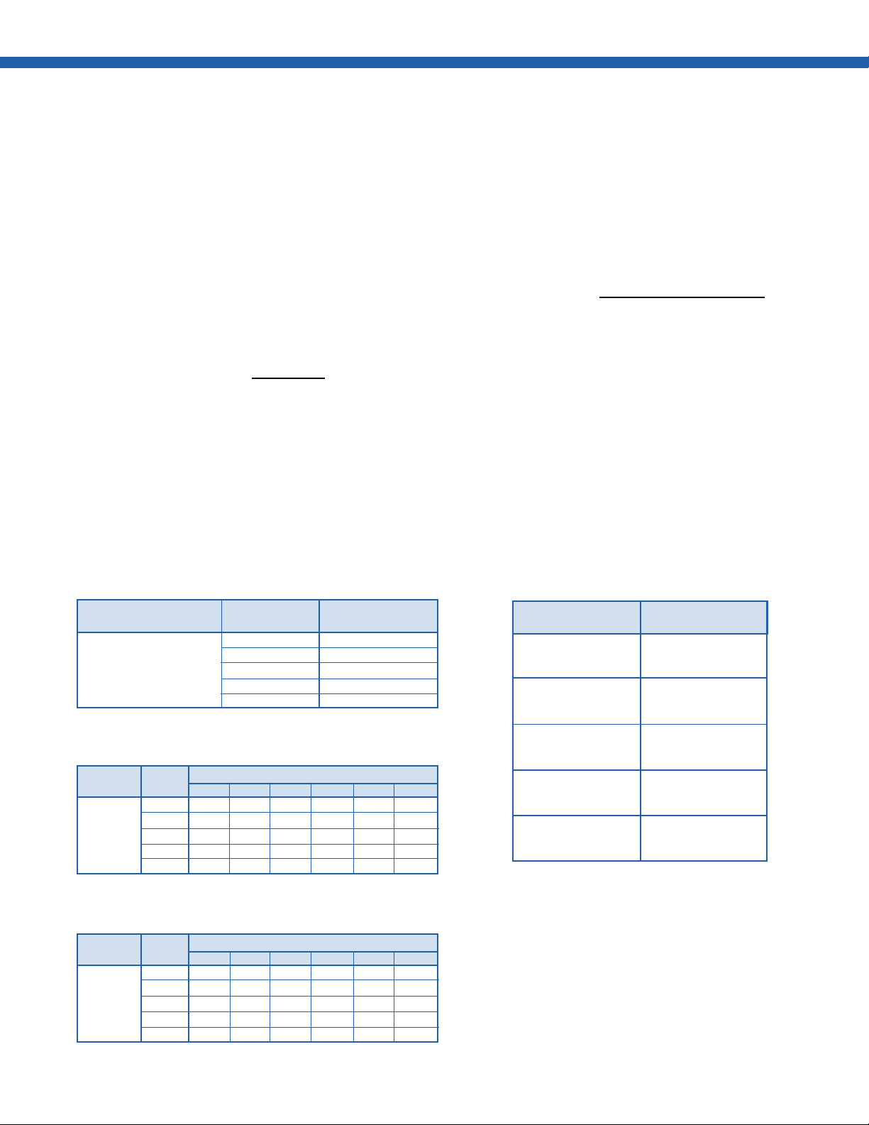
Selection Formulas
Design Load (in BTUH) = GPM * (Ent. Fluid Temp. — Leaving Fluid Temp.) x (Fluid Constant Table 1)
Average Fluid Temperature =
T.D. = Entering Fluid Temperature — Entering Air Temperature
Base Capacity =
1,000 x T.D. x Table 2 Factor x Table 4 Factor
Entering Fluid Temp. + Leaving Fluid Temp.
2
Design Load (in BTUH)
= MBH/˚T.D.
Capacity (Actual) = Capacity (Catalog) x 1,000 x T.D. x Table 2 Factor x Table 4 Factor
PD/F (Actual) = PD/F (Catalog) x Table 3 Factor
2
Page 3
Selection Procedure
Given Conditions:
BOHN DIRECT DRIVE FLUID COOLERS
BOHN DIRECT DRIVE FLUID COOLERS
Belt Drive Unit — BFF 140˚F Entering Fluid Temp.
200 GPM 120˚F Leaving Fluid Temp.
30% Ethylene Glycol Solution 10 Ft. Water Max. P.D.
90˚F Ambient Air Sea Level
Solution:
1.
Calculate Design Load
A. Determine average fluid temperature for factor selection
in Tables 2 and 3.
Average Fluid Temp. =
B. Design Load = 200 x (140—120) x 470 = 1,880,000
2.
Calculate Base Capacity
A. Determine T.D.
T.D. = 140—90 = 50˚F
140 + 120
2
= 130˚F
Fluid Cooler Correction Factor Tables
Table 1.
B. Determine Capacity Correction from Table 2
Capacity Correction Factor = 1.032
C. Determine Altitude Correction from Table 4
Altitude Correction Factor = 1.0
D.
Base Capacity =
3. Make selection from capacity tables using given conditions.
Model BFF 096, capacity of 37.57 MBH/˚T.D. meets the
requirements with “C” circuiting.
4. Convert pressure drop of selection to design condition P.D.
6.1 x .950 = 5.8 ft. water pressure drop at design condition.
5. Calculate actual unit rating at design conditions 37.57 x 1,000
x 50 x 1.032 x 1.0 = 1,938,612 BTUH.
1,880,000
1,000 x 50 x 1.032 x 1.0
= 36.43
Table 4. Altitude Correction Factors
% Fluid
Glycol Constant
0 500
Fluid 20 480
Constants 30 470
40 450
50 433
Table 2.
% Average Fluid Temp. (˚F)
Glycol 90 100 110 120 130 140
0 1.079 1.081 1.083 1.086 1.090 1.095
Capacity 20 1.030 1.035 1.042 1.047 1.054 1.058
Correction 30 1.005 1.009 1.012 1.023 1.032 1.034
Factor 40 .928 .943 .960 .984 1.000 1.010
50 .918 .926 .935 .939 .941 .973
Table 3.
% Average Fluid Temp. (˚F)
Glycol 90 100 110 120 130 140
0 .868 .853 .843 .819 .795 .789
Pressure 20 .980 .959 .935 .915 .893 .866
Drop 30 1.055 1.025 1.000 .975 .950 .923
Correction 40 1.120 1.080 1.060 1.034 1.000 .974
50 1.200 1.165 1.128 1.093 1.058 1.024
For average fluid temperatures below 90˚F or above 140˚F, contact the
factory for special application.
Altitude
(Feet) Factor
0 1.000
500 0.993
1000 0.986
1500 0.974
2000 0.963
2500 0.953
3000 0.944
3500 0.935
4000 0.927
4500 0.919
5000 0.911
5500 0.903
6000 0.895
6500 0.887
7000 0.880
3
Page 4
BOHN DIRECT DRIVE FLUID COOLERS
BOHN DIRECT DRIVE FLUID COOLERS
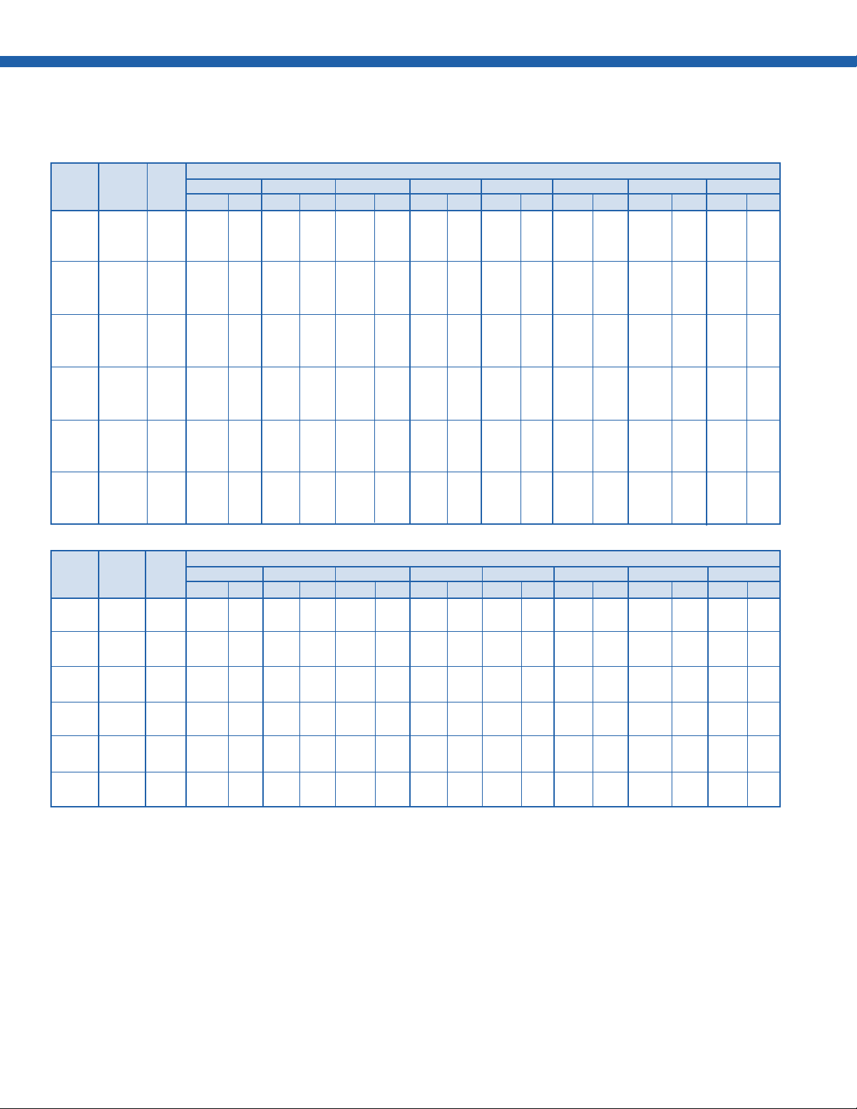
Capacity Ratings Belt Drive Fluid Coolers
Table 5A. MBH/˚T.D. — 40% Glycol — Average Fluid Temperature 130˚F (Sizes 045 - 062)
GPM
BFF Conn. Coil 30 40 50 60 70 80 90 100
Size Loc. Circ. MBH PDF MBH PDF MBH PDF MBH PDF MBH PDF MBH PDF MBH PDF MBH PDF
SE A 10.90 3.3 13.11 5.4 14.57 8.0 15.82 11.0 16.82 14.3 17.64 18.1
045 SE B 13.99 2.9 15.31 3.9 16.10 5.2 16.92 6.5 17.61 8.0 18.20 9.6
OE C 16.46 2.8 17.21 3.5 17.51 4.2
SE A 11.40 3.3 13.93 5.4 15.65 8.0 17.14 11.0 18.34 14.4 19.34 18.2
050 SE B 14.97 2.9 16.54 4.0 17.49 5.2 18.48 6.5 19.32 8.0 20.04 9.7
OE C 17.92 2.8 18.83 3.5 19.20 4.2
SE A 11.67 3.3 14.35 5.4 16.47 8.0 17.83 11.0 19.15 14.4 20.23 18.2
054 SE B 15.49 2.9 17.18 4.0 18.56 5.2 19.29 6.5 20.21 8.0 20.99 9.7
OE C 18.68 2.8 19.67 3.5 20.08 4.2
SE A 11.60 3.3 14.30 5.4 16.46 8.0 17.90 11.0 19.30 14.4 20.47 18.2
057 SE B 15.50 2.9 17.25 4.0 18.70 5.2 19.52 6.6 20.51 8.1 21.38 9.7
OE C 18.90 2.8 19.96 3.5 20.43 4.2
SE A 14.89 3.4 17.24 5.1 19.11 7.0 20.27 9.2 21.44 11.6 22.40 14.2 23.21 17.1
059 SE B 19.35 2.9 20.61 3.7 21.65 4.5 22.13 5.4
OE C 21.61 2.7
SE A 11.92 3.3 14.83 5.4 17.22 8.0 18.83 11.0 20.40 14.5 21.73 18.3
062 SE B 16.17 2.9 18.11 4.0 19.74 5.2 20.66 6.6 21.78 8.1 22.76 9.7
OE C 19.96 2.8 21.16 3.5 21.69 4.2
GPM
BFF Conn. Coil 120 140 160 180 200 250 300 350
Size Loc. Circ. MBH PDF MBH PDF MBH PDF MBH PDF MBH PDF MBH PDF MBH PDF MBH PDF
045 SE B 19.14 13.3 19.86 17.4 20.43 22.0
OE C 18.48 5.7 19.24 7.5 19.85 9.5 20.34 11.7 20.75 14.1 21.53 20.9
050 SE B 21.19 13.3 22.08 17.4 22.79 22.0
OE C 20.39 5.8 21.32 7.6 22.06 9.5 22.68 11.7 23.19 14.1 24.16 20.9
054 SE B 22.25 13.3 23.22 17.4 23.99 22.0
OE C 21.37 5.8 22.38 7.6 23.20 9.6 23.86 11.8 24.42 14.1 25.47 20.9
057 SE B 22.80 13.3 23.91 17.5 24.82 22.1
OE C 21.87 5.8 23.01 7.6 23.94 9.6 24.72 11.8 25.38 14.2 26.65 20.9
059 SE B 23.45 7.5 24.46 9.8 25.24 12.4 25.87 15.2
OE C 23.06 3.7 23.72 4.8 24.54 6.1 25.21 7.4 25.76 9.0 26.79 13.2
062 SE B 24.38 13.3 25.66 17.5 26.70 22.1
Connection Locations: SE = Same End
OE C 23.31 5.8 24.62 7.6 25.69 9.6 26.58 11.8 27.34 14.2 28.80 21.0
OE = Opposite End
4
Page 5

BOHN DIRECT DRIVE FLUID COOLERS
BOHN DIRECT DRIVE FLUID COOLERS
Capacity Ratings Belt Drive Fluid Coolers
Table 5B. MBH/˚T.D. — 40% Glycol — Average Fluid Temperature 130˚F (Sizes 065 - 114)
BFF Conn. Coil 30 40 50 60 70 80 90 100
Size Loc. Circ. MBH PDF MBH PDF MBH PDF MBH PDF MBH PDF MBH PDF MBH PDF MBH PDF
065 SE B 16.63 2.9 18.80 4.0 20.45 5.2 21.45 6.6 22.66 8.1 23.72 9.7
069 SE B 17.61 4.1 19.71 5.7 21.47 7.4 22.60 9.3 23.80 11.5 24.83 13.8
073 SE B 21.45 2.9 23.14 3.7 24.60 4.5 25.34 5.5
081 SE B 19.01 4.1 21.59 5.7 23.80 7.4 25.27 9.4 26.83 11.5 28.19 13.9
086 SE B 18.90 4.1 21.50 5.7 23.75 7.4 25.30 9.4 26.93 11.5 28.37 13.9
088
096
097 SE B 19.89 4.1 22.86 5.7 25.49 7.5 27.34 9.4 29.30 11.6 31.05 13.9
101 SE B 26.26 2.9 28.82 3.7 31.09 4.6 33.08 5.5
106
111
114 SE B 27.14 3.0 29.98 3.7 32.53 4.6 34.83 5.5
SE A 12.13 3.3 15.20 5.4 17.74 8.1 19.47 11.1 21.17 14.5 22.61 18.3
OE C 20.69 2.9 21.98 3.5 22.56 4.2
OE A 15.57 5.3 18.15 7.8 20.03 10.7 21.73 14.1 23.15 17.8 24.35 21.8
OE C 20.52 3.2 22.00 4.0 23.27 4.9 23.97 5.9
SE A 15.76 3.5 18.69 5.1 20.99 7.0 22.59 9.2 24.21 11.6 25.60 14.3 26.80 17.2
OE C 24.64 2.7
OE A 16.53 5.3 19.62 7.9 21.97 10.8 24.12 14.1 25.96 17.9 27.54 21.9
OE C 22.64 3.2 24.51 4.0 26.14 5.0 27.07 6.0
OE A 16.42 5.3 19.49 7.9 21.86 10.8 24.06 14.1 25.97 17.9 27.63 21.9
OE C 22.62 3.2 24.55 4.0 26.25 5.0 27.26 6.0
SE A 19.40 2.3 22.24 3.2 24.68 4.2 26.77 5.3 28.57 6.5 29.68 7.8
OE B 25.59 2.6 27.40 3.1 28.97 3.8
SE A 19.82 2.3 22.86 3.2 25.52 4.2 27.83 5.3 29.86 6.5 31.17 7.8
OE B 26.58 2.6 28.60 3.2 30.38 3.8
OE A 17.06 5.3 20.50 7.9 23.55 10.9 25.84 14.2 28.11 17.9 30.13 22.0
OE C 24.20 3.2 26.47 4.0 28.49 4.8 29.72 6.0
OE A 20.82 2.9 24.15 4.0 27.09 5.2 29.68 6.5 31.96 8.0 33.95 9.7
OE C 31.51 2.5
SE A 20.27 2.3 23.54 3.2 26.45 4.2 29.05 5.3 31.36 6.5 33.41 7.8
OE B 27.71 2.6 30.00 3.2 32.04 3.8
SE A 20.74 3.0 24.01 4.2 26.89 5.4 29.43 6.9 31.67 8.4 33.64 10.1
OE B 25.87 2.6 28.39 3.3 30.61 4.1 32.58 4.9
OE A 21.23 2.9 24.78 4.0 27.98 5.2 30.87 6.6 33.46 8.1 35.77 9.7
OE C 33.11 2.5
GPM
BFF Conn. Coil 120 140 160 180 200 250 300 350
Size Loc. Circ. MBH PDF MBH PDF MBH PDF MBH PDF MBH PDF MBH PDF MBH PDF MBH PDF
065
069
073
081
086
088 OE B 31.53 5.2 32.96 6.8 34.48 8.6 35.72 10.5 36.74 12.7 38.67 18.8
096 OE B 33.34 5.2 35.05 6.8 36.87 8.6 38.37 10.6 39.63 12.7 42.02 18.8
097
101 SE B 36.41 7.6 38.44 9.9 40.49 12.5 42.18 15.3 43.59 18.4
106 OE B 35.51 5.2 37.61 6.8 39.83 8.6 41.69 10.6 43.28 `12.7 36.36 18.8
111 OE B 35.89 6.7 38.00 8.8 40.08 11.1 41.81 13.7 43.27 16.4
114 SE B 38.75 7.6 41.26 9.9 43.80 12.5 45.92 15.4 47.73 18.5
Connection Locations: SE = Same End
SE B 25.48 13.4 26.87 17.5 28.00 22.1
OE C 24.32 5.8 25.73 7.6 26.89 9.6 27.86 11.8 28.68 14.2 30.27 21.0
SE B 26.52 19.0
OE C 25.67 8.1 27.00 10.7 28.08 13.5 28.96 16.6 29.70 19.9
SE B 27.29 7.5 28.84 9.8 30.08 12.4 31.10 15.3 31.95 18.4
OE C 26.74 3.8 27.77 4.8 29.05 6.1 30.10 7.5 30.99 9.0 32.70 13.3 33.91 18.3
SE B 30.43 19.1
OE C 29.31 8.2 31.08 10.7 32.53 13.5 33.72 16.6 34.72 20.0
SE B 30.80 19.1
OE C 29.65 8.2 31.60 10.7 33.21 13.5 34.56 16.7 35.71 20.0
SE A 32.09 10.7
SE C 29.23 2.5 31.37 3.3 33.07 4.1 34.46 5.1 35.00 6.1 37.09 9.1 38.57 12.5 39.67 16.4
SE A 33.98 10.7
SE C 30.77 2.5 33.23 3.3 35.24 4.2 36.89 4.1 37.57 6.1 40.12 9.1 41.96 12.5 43.35 16.4
SE B 34.02 19.2
OE C 32.62 8.2 35.01 10.8 37.00 13.6 38.68 16.7 40.11 20.1
OE A 36.73 13.3
OE C 34.88 3.4 37.56 4.5 39.14 5.6 40.85 6.9 42.30 8.3 45.06 12.3 47.01 16.9
SE A 36.23 10.8 38.94 14.1 41.16 17.8 43.01 21.9
SE C 32.60 2.5 35.50 3.3 37.91 4.2 39.93 5.1 40.80 6.2 44.01 9.1 46.37 12.5 48.19 16.4
SE A 36.46 13.9
SE C 33.60 3.2 36.34 4.2 38.57 5.3 40.44 6.5 41.37 7.9 44.28 11.6 46.39 16.0
OE A 39.72 13.3 42.22 17.4 44.77 22.0
OE C 37.03 3.4 40.24 4.5 42.21 5.6 44.34 6.9 46.16 8.3 49.72 12.3 52.29 17.0
OE = Opposite End
GPM
5
Page 6

BOHN DIRECT DRIVE FLUID COOLERS
BOHN DIRECT DRIVE FLUID COOLERS
Capacity Ratings Belt Drive Fluid Coolers
Table 5C. MBH/˚T.D. — 40% Glycol — Average Fluid Temperature 130˚F (Sizes 121 - 228)
BFF Conn. Coil 30 40 50 60 70 80 90 100
Size Loc. Circ. MBH PDF MBH PDF MBH PDF MBH PDF MBH PDF MBH PDF MBH PDF MBH PDF
121
136 SE B 26.08 2.9 29.86 3.8 33.37 4.9 36.61 6.0 39.60 7.2
139
145 OE B 28.82 3.2 32.05 4.1 35.00 5.0 37.67 6.0
151 SE B 26.41 2.9 30.36 3.9 34.08 4.9 37.57 6.0 40.83 7.2
159 OE B 29.28 3.2 32.67 4.1 35.81 5.0 38.68 6.1
167 OE B 26.08 2.9 29.85 3.8 33.34 4.8 36.57 6.0 39.54 7.2
179 OE B 29.79 3.2 33.39 4.1 36.74 5.0 39.87 6.1
182 OE B 26.33 2.9 30.21 3.8 33.85 4.9 37.24 6.0 40.39 7.2
200 SE B 23.07 3.1 27.53 4.3 31.87 5.6 36.06 7.1 40.08 8.8 43.90 10.6
209 OE B 26.60 2.9 30.62 3.8 34.42 4.9 38.00 6.0 41.37 7.2
228 SE B 23.14 3.1 27.66 4.3 32.08 5.6 36.38 7.1 40.54 8.8 44.55 10.6
SE A 21.04 3.0 24.45 4.2 27.52 5.4 30.25 6.9 32.70 8.5 34.87 10.2
OE B 26.47 2.6 29.18 3.3 31.59 4.1 33.75 4.9
OE A 22.54 3.7 26.64 5.2 30.50 6.8 34.09 8.6 37.41 10.6 40.45 12.7
OE C 37.98 3.2
SE A 21.44 3.0 25.07 4.2 28.40 5.5 31.42 6.9 34.17 8.5 36.66 10.2
OE B 27.34 2.6 30.31 3.3 33.00 4.1 35.45 4.9
SE A 22.21 3.7 26.11 5.1 29.72 6.7 33.02 8.5 36.03 10.4 38.76 12.6
SE C 35.14 2.9
OE A 22.71 3.8 26.94 5.2 30.97 6.8 34.77 8.6 38.35 10.6 41.68 12.7
OE C 39.19 3.2
SE A 22.38 3.7 26.40 5.1 30.15 6.7 33.63 8.5 36.84 10.5 39.79 12.6
SE C 36.07 2.9
SE A 18.30 3.0 22.62 4.4 26.72 6.1 30.57 8.0 34.14 10.1 37.44 12.4 40.47 14.9
SE C 34.35 2.8 37.27 3.4
SE A 22.57 3.7 26.71 5.1 30.63 6.7 34.32 8.5 37.77 10.5 40.98 12.6
SE C 37.19 2.9
SE A 18.36 3.0 22.74 4.4 26.93 6.1 30.90 8.0 34.62 10.1 38.10 12.4 41.32 15.0
SE C 35.02 2.8 38.10 3.4
OE A 18.65 3.7 23.24 5.5 27.76 7.6 32.16 9.9 36.42 12.6 40.52 15.5 44.42 18.7
OE C 31.12 2.5 35.21 3.2 39.12 3.9 42.84 4.7
SE A 18.43 3.0 22.88 4.4 27.16 6.1 31.26 8.0 35.16 10.1 38.84 12.4 42.29 15.0
SE C 35.79 2.8 39.06 3.4
OE A 18.67 3.7 23.29 5.5 27.85 7.6 32.33 9.9 36.69 12.6 40.93 15.5 45.02 18.7
OE C 35.60 3.2 39.65 3.9 43.55 4.7
GPM
BFF Conn. Coil 120 140 160 180 200 250 300 350
Size Loc. Circ. MBH PDF MBH PDF MBH PDF MBH PDF MBH PDF MBH PDF MBH PDF MBH PDF
121 OE B 37.43 6.7 39.84 8.8 42.22 11.1 44.22 13.7 45.92 16.5
136 SE B 44.84 9.9 48.56 13.0 52.10 16.4 55.10 20.1
139 OE B 39.72 6.8 42.64 8.9 45.52 11.2 47.98 13.7 50.11 16.5
145 OE B 42.39 8.3 45.57 10.9 48.64 13.7 51.23 16.9 53.43 20.3
151 SE B 46.69 9.9 51.03 13.0 55.20 16.4 58.81 20.2
159 OE B 43.76 8.3 47.42 10.9 50.89 13.8 53.86 16.9
167
179 OE B 45.48 8.3 49.67 10.9 53.68 13.8 57.16 16.9 60.21 20.4
182 OE B 46.03 9.9 50.32 12.9 54.33 16.3 57.80 20.1
200 SE B 50.98 14.5 56.78 19.0
209 OE B 47.49 9.9 52.29 13.0 56.82 16.4 60.79 20.1
228
Connection Locations: SE = Same End OE = Opposite End
SE A 38.05 14.0
SE C 34.95 3.2 38.01 4.2 40.54 5.3 42.67 6.5 43.78 7.9 47.17 11.6 49.67 16.0
OE A 45.24 17.5
OE C 43.12 4.4 47.45 5.8 51.10 7.3 53.36 9.0 55.89 10.8 60.84 16.0
SE A 40.42 14.0 43.89 18.3
SE C 36.98 3.2 40.55 4.2 43.57 5.3 46.16 6.6 47.57 7.9 51.82 11.7 55.02 16.0 57.51 21.0
SE A 42.97 17.3
SE C 39.75 3.9 43.59 5.2 46.80 6.5 49.52 8.0 51.08 9.6 55.41 14.2 58.57 19.5
OE A 47.11 17.5
OE C 44.90 4.4 49.82 5.8 54.09 7.4 56.85 9.0 59.93 10.9 66.10 16.0 70.69 22.0
SE A 44.45 17.3
SE C 41.07 3.9 45.29 5.2 48.88 6.5 51.96 8.0 53.80 9.6 58.84 14.2 62.59 19.6
OE B 44.77 9.9 48.67 12.9 52.28 16.3 55.37 20.0
SE C 43.42 4.7 46.78 6.1 50.49 7.7 53.67 9.5 55.70 11.4 60.92 16.8 64.78 23.1
SE A 46.20 17.3
SE C 42.65 4.0 47.37 5.2 51.47 6.5 55.05 8.0 57.26 9.7 63.31 14.3 67.91 19.6
SE A 46.65 20.6
SE C 43.60 4.7 48.33 6.1 52.42 7.7 55.97 9.5 58.29 11.4 64.25 16.8 68.74 23.1
OE A 51.29 25.7
OE C 49.70 6.5 55.81 8.5 61.22 10.7 65.25 13.2 69.31 15.8 77.54 23.4
SE A 48.12 20.6
SE C 45.00 4.7 50.20 6.1 54.76 7.7 58.79 9.5 61.51 11.4 68.49 16.9
SE B 52.08 14.6 58.44 19.1
OE C 50.85 6.5 57.48 8.5 63.47 10.8 68.10 13.2 72.77 15.9 82.50 23.4
GPM
6
Page 7

Optional Accessories
BOHN DIRECT DRIVE FLUID COOLERS
BOHN DIRECT DRIVE FLUID COOLERS
Optional Cooling Coils
The standard coil construction and fin pattern is compatible with
most system environments. Where the fluid cooler is subject to
a contaminated or corrosive airstream, special coils may be
required. A vailable for these applications are coils with wider fin
spacing for easier cleaning, coils Heresite® coated to reduce
corrosion (up through 169" long cabinet), polyester painted fins
for salt atmosphere protection (BOHNGUARD®), and copper fin/
copper tube coils for all models.
Extended Lube Lines
Available on belt drive units, extended lube lines are factory
installed with external grease fittings to make lubrication routine.
Low Ambient Operation
Fan Control
Fan control is an automatic operation to control the leaving fluid
temperature by cycling fans off in sequence. Each fan section,
with the exception of the number one cell, operates under the
control of an individual thermostat which senses leaving fluid
temperature. As the fluid temperature drops below the set point
of each thermostat, that fan section cycles off. The number one
fan section remains on at the full fan cycling. Cooler capacity
drops to the approximate capacity percentages shown in the table
below.
Connection Manifold Kit
This field installed kit converts the standard dual circuit cooler
(direct drive models and belt drive models) to one having a single
inlet and outlet connection.
Sealtite Wiring
Sealtite wiring is watertight, flexible conduit and fittings for fan
motors. It is factory installed and replaces the standard THW
wiring.
NOTE: The standard fan control packages use individual
thermostats to cycle fans. This method of control will allow leaving
fluid temperatures to fluctuate between fan cycling points. For
applications requiring precise fluid temperature control during
all periods of operation, contact the factory applications
department.
Multiple Contactor Fan Cycling:
Consists of a factory mounted and wired, weatherproofed
enclosure containing starting contactors (with holding coils) and
thermostat(s) with sensing bulb strapped to coil outlet header.
Specify control voltage on order: 24V, 115V or 208-230V
available.
The fan control thermostats must be field adjusted to meet design
requirements. The maximum temperature setting for the standard
control thermostat is 100˚F. For applications requiring precise
fluid temperature control during all periods of operation, contact
the factory applications department.
Table 6. Capacity at Maximum Fan Control
One Fan Cell Operating
Table 7. Belt Drive Fluid Cooler Volume in Gallons
BFF Volume BFF Volume BFF Volume
Unit Gallons Unit Gallons Unit Gallons
045 19.3 086 26.3 139 43.1
050 19.3 088 33.7 145 52.5
054 19.3 096 33.7 151 52.9
057 19.3 097 26.3 159 52.5
059 24.3 101 41.1 167 62.0
062 19.3 106 26.3 179 52.5
065 19.3 111 43.1 182 62.0
069 26.3 114 41.1 200 76.4
073 24.3 121 43.1 209 62.0
081 26.3 136 52.9 228 76.4
Fans % Total
Available Capacity
2 55%
3 40%
4 33%
5 28%
6 25%
7
Page 8

BOHN DIRECT DRIVE FLUID COOLERS
BOHN DIRECT DRIVE FLUID COOLERS
Physical / Dimensional Data
Diagram 1.Dimensional Diagram for models BFF 45-228
8
Page 9

BOHN DIRECT DRIVE FLUID COOLERS
BOHN DIRECT DRIVE FLUID COOLERS
Dimensional and Physical Data
Table 8A. Dimensions
BFF Dimensions 48" Fans
Size A D E F G J K L M R S Y Qty. RPM CFM
045 114 110 --- ---- 315/82113/
5
050 114 110 --- ---- 31
054 114 110 --- ---- 31
/82113/
5
/82113/
057 114 110 --- ---- 315/82113/
1
/
059 114 110 --- ---- 30
062 114 110 --- ---- 31
065 114 110 --- ---- 31
069 169 165 82 83 31
073 114 110 --- --- 30
4
5
/82113/
5
/82113/
5
/82113/
1
/
4
081 169 165 82 83 315/82113/
5
086 169 165 82 83 31
088 169 165 82 83 30
096 169 165 82 83 30
097 169 165 82 83 31
101 169 165 82 83 28
/82113/
1
/42113/162113/16421/4421/461/2115/
1
/42113/162113/16421/4421/461/2115/
5
/82113/
7
/82113/162113/16421/4421/4615/
106 169 165 82 83 301/42113/162113/16421/4421/461/2115/
1
111 224 220 109
114 169 165 82 83 28
121 224 220 109
136 224 220 109
139 224 220 109
/21101/2301/42113/162113/16421/4421/4611/
7
1
/21101/2301/42113/162113/16421/4421/4611/
1
/21101/2287/82113/162113/16421/4421/4615/
1
/21101/2301/42113/162113/16421/4421/4611/
/82113/162113/16421/4421/4615/
145 279 275 821/21101/2301/42113/162113/16421/4421/4615/
1
151 224 220 109
159 279 275 82
167 334 330 109
179 279 275 82
182 334 330 109
200 334 330 1091/21101/2299/
209 334 330 109
228 334 330 109
/21101/2287/82113/162113/16421/4421/4615/
1
/21101/2301/42113/162113/16421/4421/4615/
1
/21101/2301/42113/162113/16421/4421/4615/
1
/21101/2301/42113/162113/16421/4421/4615/
1
/21101/2301/42113/162113/16421/4421/4615/
1
/21101/2301/42113/162113/16421/4421/4615/
1
/21101/2299/
16
16
16
225/
225/
237/16417/16417/
16
237/16417/16417/
16
237/16417/16417/
16
237/16417/16417/
8
237/163913/163513/1661/2115/
16
237/16417/16417/
16
237/16417/16417/
16
237/16417/163913/1661/2115/
8
237/163913/163513/1661/2115/
16
237/16417/163913/1661/2115/
16
237/16417/163913/1661/2115/
16
237/16417/163913/1661/2115/
16
16
16
16
16
16
61/2115/
61/2115/
61/2115/
61/2115/
61/2115/
61/2115/
2113/162113/16421/4421/4615/
2113/162113/16421/4421/4615/
16
--- 2 415 32,800
16
--- 2 470 35,000
16
--- 2 470 34,400
16
--- 2 600 51,200
16
--- 2 470 31,200
16
--- 2 600 50,100
16
--- 2 600 48,200
16
--- 3 415 44,000
16
--- 2 600 49,200
16
--- 3 470 51,600
16
--- 3 600 76,800
16
--- 3 470 46,800
16
--- 3 545 54,300
16
--- 3 600 72,300
16
27/
16
--- 3 545 58,800
16
--- 3 600 66,000
16
23/
16
--- 4 470 72,000
16
27/
16
--- 3 600 67,600
16
23/
16
--- 4 545 78,000
16
27/
16
--- 4 545 82,400
16
23/
16
--- 4 600 99,200
16
27/
16
821/
2
5 470 81,500
16
27/
16
--- 4 600 100,400
16
27/
16
821/
2
5 545 94,000
16
27/
16
110 6 470 101,400
16
27/
16
821/
2
5 600 114,500
16
27/
16
110 6 545 117,000
16
27/
16
110 6 545 123,600
16
27/
16
110 6 600 142,200
16
27/
16
110 6 600 150,600
9
Page 10

BOHN DIRECT DRIVE FLUID COOLERS
BOHN DIRECT DRIVE FLUID COOLERS
Table 8B. Physical Data
Motors Internal Approximate
BFF Full Load Amps (Three Phase) Volume Dry Weight
Size HP 208V 230V 460V Gallons (Lbs.)
045 11/
050 2 13.4 13.2 6.6 19.3 1340
054 2 13.4 13.2 6.6 19.3 1380
057 5 29.2 26.4 13.2 19.3 1370
059 2 13.4 13.2 6.6 24.3 1540
062 5 29.2 26.4 13.2 19.3 1420
065 5 29.2 26.4 13.2 19.3 1450
069 1
073 5 29.2 26.4 13.2 24.3 1610
081 2 20.1 19.8 9.9 26.3 2110
086 5 43.8 39.6 19.8 26.3 2095
088 2 20.1 19.8 9.9 33.7 2335
096 3 27.9 25.2 12.6 33.7 2380
097 5 43.8 39.6 19.8 26.3 2395
101 3 27.9 25.2 12.6 41.1 2460
106 5 43.8 39.6 19.8 26.3 2440
111 2 26.8 26.4 13.2 43.1 2910
114 5 43.8 39.6 19.8 41.1 2580
121 3 37.2 33.6 16.8 43.1 2970
136 3 37.2 33.6 16.8 52.9 3370
139 5 58.4 52.8 26.4 43.1 3050
145 2 33.5 33.0 16.5 52.5 3850
151 5 58.4 52.8 26.4 52.9 3450
159 3 46.5 42.0 21.0 52.5 3900
167 2 40.2 39.6 19.8 62.0 4525
179 5 73.0 66.0 33.0 52.5 3950
182 3 55.8 50.4 25.2 62.0 4575
200 3 55.8 50.4 25.2 76.4 4995
209 5 87.6 79.2 39.6 62.0 4695
228 5 87.6 79.2 39.6 76.4 5115
2
1
/
2
11.0 10.0 5.0 19.3 1280
16.5 15.0 7.5 26.3 1960
10
Page 11

Engineering Specifications
BOHN DIRECT DRIVE FLUID COOLERS
BOHN DIRECT DRIVE FLUID COOLERS
Unit Cabinet -
Casings shall be constructed of heavy gauge corrosion resistant
aluminum, or galvanized steel, thoroughly reinforced with bolted
gussets. Full width baffles shall divide the individual fan sections.
Motor access panels shall be provided in each fan section.
Cabinet mounting frames and mounting legs shall be constructed
of heavy galvanized steel. The legs shall be shipped with the
unit for field installations.
Coil -
Coil shall be constructed of plate type, die formed, aluminum
fins mechanically bonded to copper tubes; fins shall employ full
height, self-spacing collars which completely cover tube surface.
Coil shall be pressure and leak tested at 425 PSIG air under
warm water, evacuated, dehydrated and sealed with caps on
connections.
Fans -
Fans, each driven by its own motor, shall be selected to cover a
large percentage of the coil face area. Fans shall be statically
and dynamically balanced before shipment. Low tip speeds shall
provide quiet operation.
Fan Motors -
Motors shall be NEMA type “T” frame, open drop-proof with
grease lubricated ball bearings. They shall be thermally protected
against burnout, and may be started by a single contactor. Motors
shall be factory wired with leads marked and terminated in a
weatherproof junction box located on the outside of the unit. They
shall be positioned within unit casing for weather protection.
Adjustable motor mount bases and large, easy access motor
compartment panels. Available in 208V, 230V, 460V and 575V,
three phase 60 Hz. models: and 200V, 380V and 415V, three
phase 50 Hz. models.
Fan Guards -
Guards shall be constructed of heavy gauge, close meshed steel
wire that is zinc plated and iridite dipped to prevent corrosion.
U.L. Listing -
All 60 Hz. models (except 575V) shall be U.L. listed.
Drives & Bearings -
Each fan shall be equipped with a heavy duty , weather protected,
pillow block bearing with lubricating fitting accessible through
the motor access panel. Fan shafts shall be polished steel,
precision machined and coated with corrosion resistant dressing.
V-belt and cast iron drive pulleys shall be matched for heavy
duty continuous operation.
11
Page 12

Bohn is a product line of
Heatcraft Refrigeration Products
2175 W. Park Place Blvd.
Stone Mountain, GA 30087 • (770) 465-5600 • Fax: (770) 465-5990
Visit our web site at
www.heatcraftrpd.com
for technical literature online.
 Loading...