

Page 1
Technical Guide
BNHGDTB
March 2011
Replaces BN-HGDTB, July 2009
Page 2
L
U
®
C
US
Table of Contents
Overview ......................................................................................2
System Features .........................................................................3
Condensing Unit ................................................................. 4-13
Mohave Hot Gas Defrost Quick Reference .......................5
Mohave Hot Gas Unit Cooler Typical Factory Piping . 14
Medium Prole Evaporator ...........................................15-17
Large Unit Cooler .............................................................18-23
Hot Gas Defrost Systems ...............................................24-28
Refrigeration and Defrost Operation ........................ 29-31
Mohave Hot Gas Defrost Cycle Diagrams ............... 32, 33
Overview
The Mohave™ advanced hot gas defrost refrigeration system
with controller utilizes hot gas to greatly reduce defrost
times and operates in all outdoor ambient temperatures.*
This leads to increased energy eciency and product
integrity in a refrigeration system that can be used in a
greater variety of environmental conditions. This system
utilizes a state-of-the-art electronic defrost controller with
a proprietary control scheme that allows the system to
continually operate at its most optimal level.
*Tested to -20°F ambient.
Hot Gas Control Board Features & Benets
• The Mohave controller completely manages timing and sequence of defrost
• Point to point wiring to all control components
• Automatically compensates for changes in outdoor temperatures
• Quick and easy troubleshooting
• Monitors all pressures, temperatures, and setpoints in real time.
• Easily programmable through a menu driven interface
• The control board with conformal coating will handle the toughest conditions
• LED indicators on the board clearly show system status
• Remote alarm notication
• Signicant energy savings over electric defrost systems
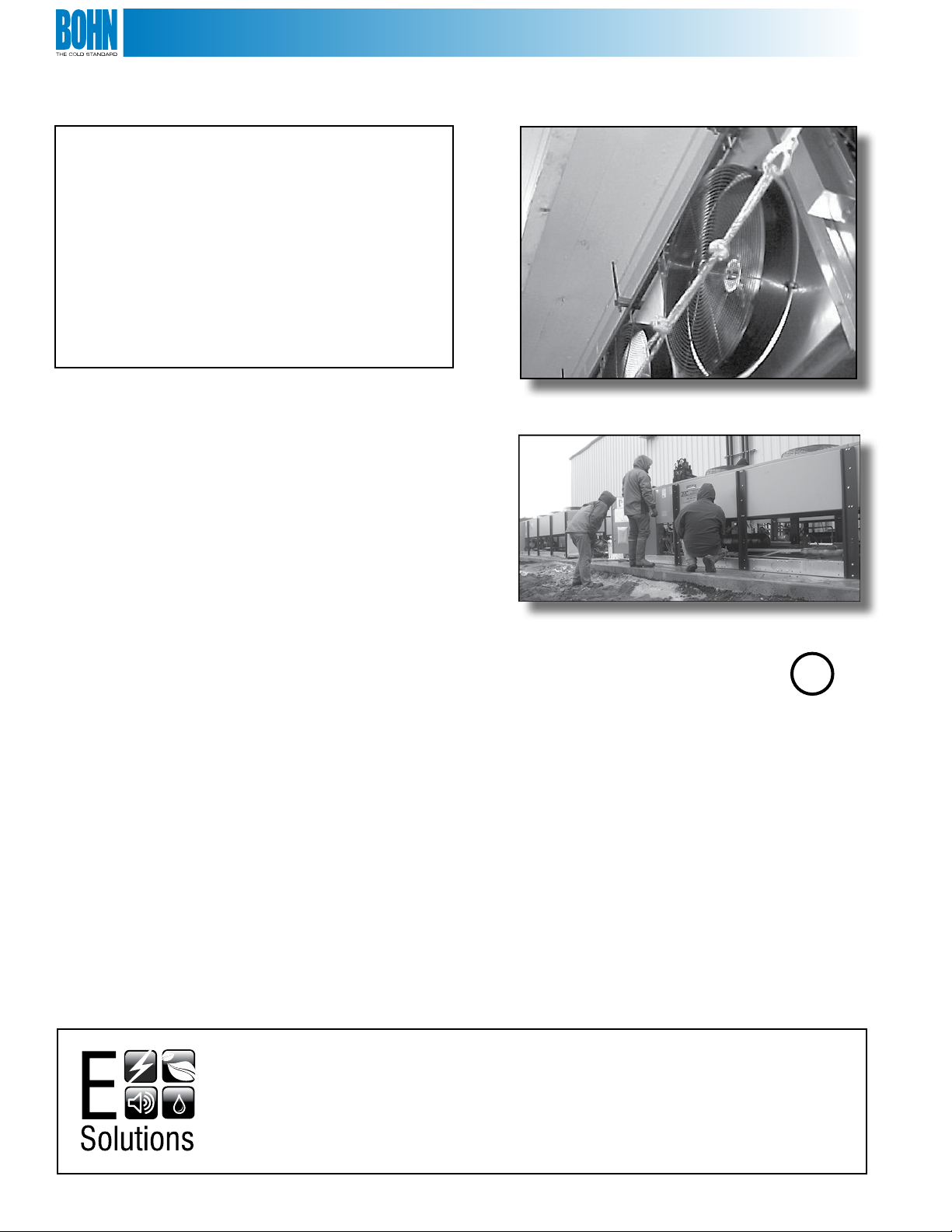
E Solutions™ branded products and options are designed to exceed current energy and environmental
standards. We have made a conscious commitment to developing environmentally innovative products
that allow our customers to make energy ecient, eco-conscious choices. Products included in the
E Solutions portfolio reduce costs, improve bottom lines, and enhance both equipment performance and
service life. The Mohave™ Advanced Hot Gas Defrost System contains a sophisticated controller with sensors
that gather information and assess the condition of the system to defrost more eciently, resulting in energy
savings. To further increase energy savings, EC motors are available for some evaporator models.
2
Page 3
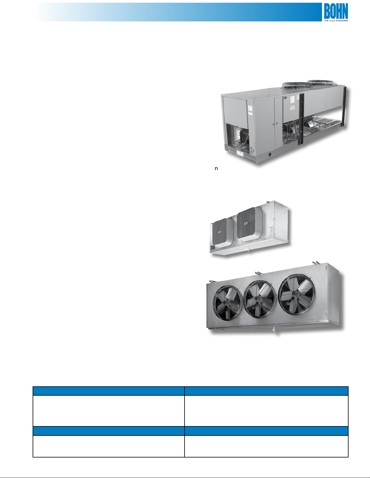
Main System Features
Condensing Unit
• Integral condenser sub-cooling circuit in condenser for added capacity and vapor free liquid
• Floating Tube™ condenser coil design
• Electronic defrost controller
• Pressure or ambient fan cycling for head pressure control
• Electronic pressure regulator for defrost control
• Anti-short cycling protection
• High pressure and low pressure controls
• Oil pressure safety control
• Easily accessible control box
• High eciency Copeland Discus® compressors with poe oil
• Thermally protected permanently lubricated ball bearing condenser fan
motor(s)
• Receivers are sized for sucient pumpdown capacity with inlet and outlet service valves
• Cabinet is constructed from painted galvanized steel
• Replaceable core liquid line lter drier
• Replaceable core suction lter
Evaporators
• All components are factory installed and wired
• Independent or single point power supply from condensing unit
• 4 and 6 FPI medium and large unit coolers
Features:
• Mounted TXV and distributor nozzle
• Mounted check valves
• Mounted liquid line solenoid
• Mounted suction “P” trap
• Electric drain pan heater standard (mounted hot gas drain loop optional)
• Mounted and wired control contactors
Electric Vs. Hot Gas Drain Pan
Electric Drain Pan Heater (Std) Advantages
• In this option, the drain pan surface is heated with low
wattage electric heater(s)
• The electrical power requirements to the evaporator are
unchanged
Hot Gas Drain Pan Loop Advantages
• In this option, hot refrigerant gas passes through a loop
of copper tubing that heats the drain pan surface before it
defrosts the evaporator coil
• Lower cost solution
• Defrost is even quicker because more hot gas is available to
defrost the evaporator coil
• In applications where there is limited evaporator accessibility (ex:
controlled atmosphere rooms)
3
Page 4
Vertical Air Discharge Condensing Unit
The BDV Outdoor Discus Condensing Unit features a leak
resistant design which includes:
• The Floating Tube™ condenser coil design. Refrigerant
carrying copper tubes do not contact any metal support
sheets; instead, the coil is constructed with expanded
anchor tubes which support the coil construction and
do not carry refrigerant. The coil design eliminates one
of the major causes of leaks in refrigeration systems
• Limited ve year warranty against condenser tube sheet
and center support leaks
• Designed for use with R-404A, R-507, R-22
• Polyol Ester Oil charge on all units
• Pre-bent copper tubes minimize braze joints on
internal piping
• Encapsulated high pressure switch eliminates
capillary tubes
• Sentronic oil safety control
• ServiceMate™ diagnostic module
• Electronic defrost controller
Other Standard Features
• High eciency Copeland Discus® compressors
• Thermally protected, permanently lubricated ball
bearing condenser fan motors
• Electrical controls including compressor contactor,
relays, and electronic controls are located in easily
accessible control box with a hinged cover
• Receivers sized for sucient pump down capacity with
inlet and outlet service valves
• Cabinet constructed from pre-painted steel
• Convenient access panels for easy servicing to internal
components
• Suction and discharge vibration eliminators
• Separate subcooling circuit in condenser for added
capacity and vapor free liquid
• Replaceable core liquid line lter drier and sight glass
• Replaceable core suction lter
• Anti-short cycle timer
• Suction accumulator
• Condenser fan cycling (pressure or temperature)
• Pressure relief valve on receiver
• Crankcase heater
Optional Features
• Oil separator
• Fused disconnect switch
• Non-fused disconnect switch
• Coated condenser coils for protection
against metal erosion in harsh environments
• Manual reset high pressure switch
• Low ambient kit with insulated, heated receiver
• Phase loss protection
• Adjustable head pressure control valves
• Evaporator control contactors mounted in condensing unit
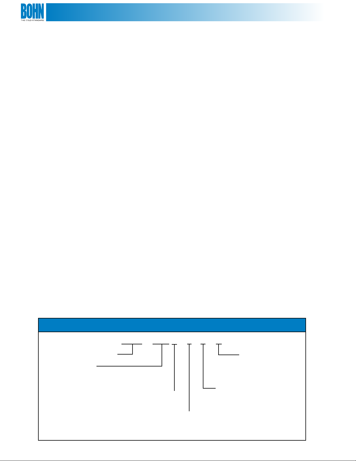
Nomenclature
BDV 150 2 L 6 C
BDV – Vertical Air Discharge
Nominal Horsepower
060 – 6 HP
075 – 7.5 HP
076 – 7.5 HP
080 – 8 HP
090 – 9 HP
100 – 10 HP
120 – 12 HP
150 – 15 HP
200 – 20 HP
250 – 25 HP
300 – 30 HP
350 – 35 HP
400 – 40 HP
Hot Gas Defrost – 2
Refrigerant
6 – R-404A or R-507 or R-22
Application (SST)
L – Low (0°F to -40°F)
M – Medium (30°F to -10°F)
4
Electrical Characteristics
C – 208-230/3/60
D – 460/3/60
K – 230/3/60
E – 575/3/60
Page 5
The Mohave Controller
• Fast, dependable, and ecient positive defrost of
evaporators
• Five to ten minute defrost times in most applications
• Will operate eciently in all outdoor ambient
conditions*
• Signicant energy savings over electric defrost systems
• Highest levels of product integrity through more stable
box temperatures
*Tested to -20°F ambient.
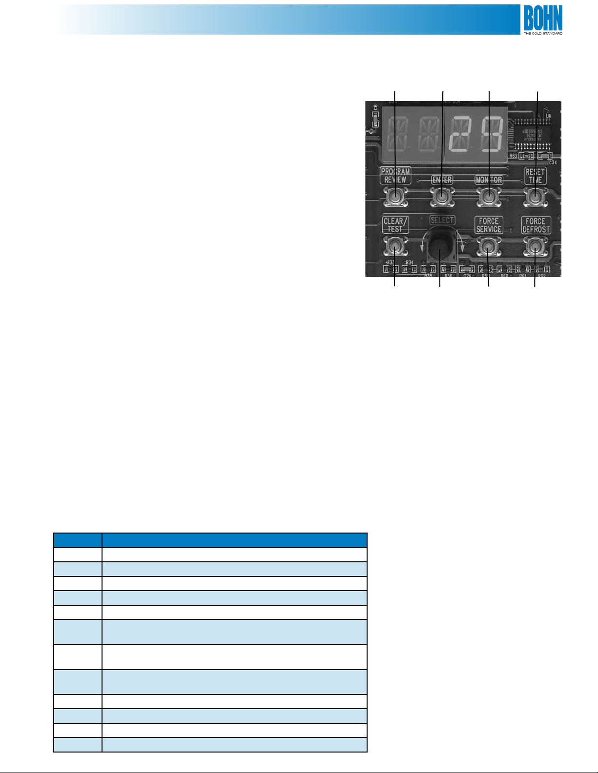
Mohave Hot Gas Defrost Controller
Quick Reference Guide
Control Buttons
Program Review: Review or Change the Program Settings
Enter: Accepts changes into memory
Monitor: View Current Operating Conditions of the System
Reset Time: Resets the time clocks of the microprocessor to 0
Program
Review
Clear/
Test
Enter
Selection
Knob
Monitor
Force
Service
Reset
Time
Force
Defrost
Clear/Test: Clear ignores program selections prior to pressing Enter and terminates Service Mode. Test causes the system to
cycle through all of the outputs for troubleshooting
Select Knob: Used for Cycling through Monitoring and Programming Parameters
Force Service: Press this button twice to cause the system to pump down and remain o until the Clear button is pressed
Force Defrost: System will pump down and begin a defrost cycle. This will not aect the normally scheduled defrosts
Service Switch
This toggle switch may be placed in the “on” position to force the system into Service Mode. The compressor will pump down
and shut o. The evaporator fans will de-energize. The system can be left in service mode for seasonal “OFF” situations.
Operating Modes
Mode Description
OFF Compressor O
COOL Compressor On in Cooling Normal Cooling Operation
PMPD System in Pump Down Mode
SERV Service Mode, System is O
DELY Timed Delay
DEF1 Defrost Stage 1
Pre-Defrost or Bypass Mode
DEF2 Defrost Stage 2
Defrost Mode
DEF3 Defrost Stage 3
Post Defrost Equalization or Drain Down Mode
FREZ Refreeze Mode
TEST Test Mode
SERV Service Mode
EVAC Evacuation Mode
5
Page 6
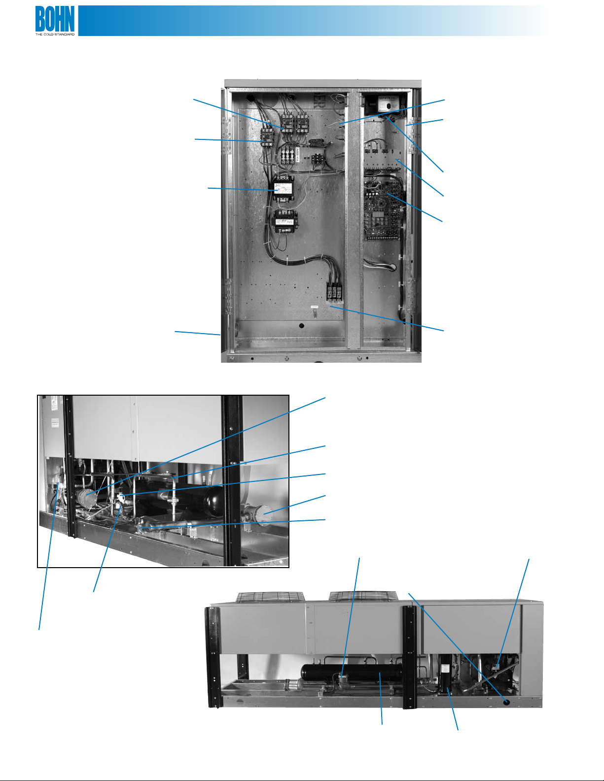
Electrical Box Features
Condenser Fan
Contactors
Compressor Contactor
Control Circuit
Transformers
Electrical Service
Knockouts
Typical Internal Piping
Control Circuit Fuses
& Service Switch
All Service Controls are located
in a separate electrical panel
allowing eld adjustments
without disconnecting power to
the unit
Oil
Pressure Switch
ServiceMate™ Diagnostic
Module
Mohave Hot Gas System
Controller
Main Power Block
Replaceable Core Liquid
Filter Drier
3-Way Valve
Electronic Pressure
Regulator
Pre-bent Internal Piping
Prevents Braze Joints
Defrost
Solenoid
Replaceable Core
Suction Filter
Bypass
Solenoid
Suction Stop
Solenoid
Liquid Receiver with Service Valves Allow Charge Isolation
Easily Accessible
Discus Compressor
Galvanized Steel
Base with Rigging Points
Suction Accumulator
6
Page 7
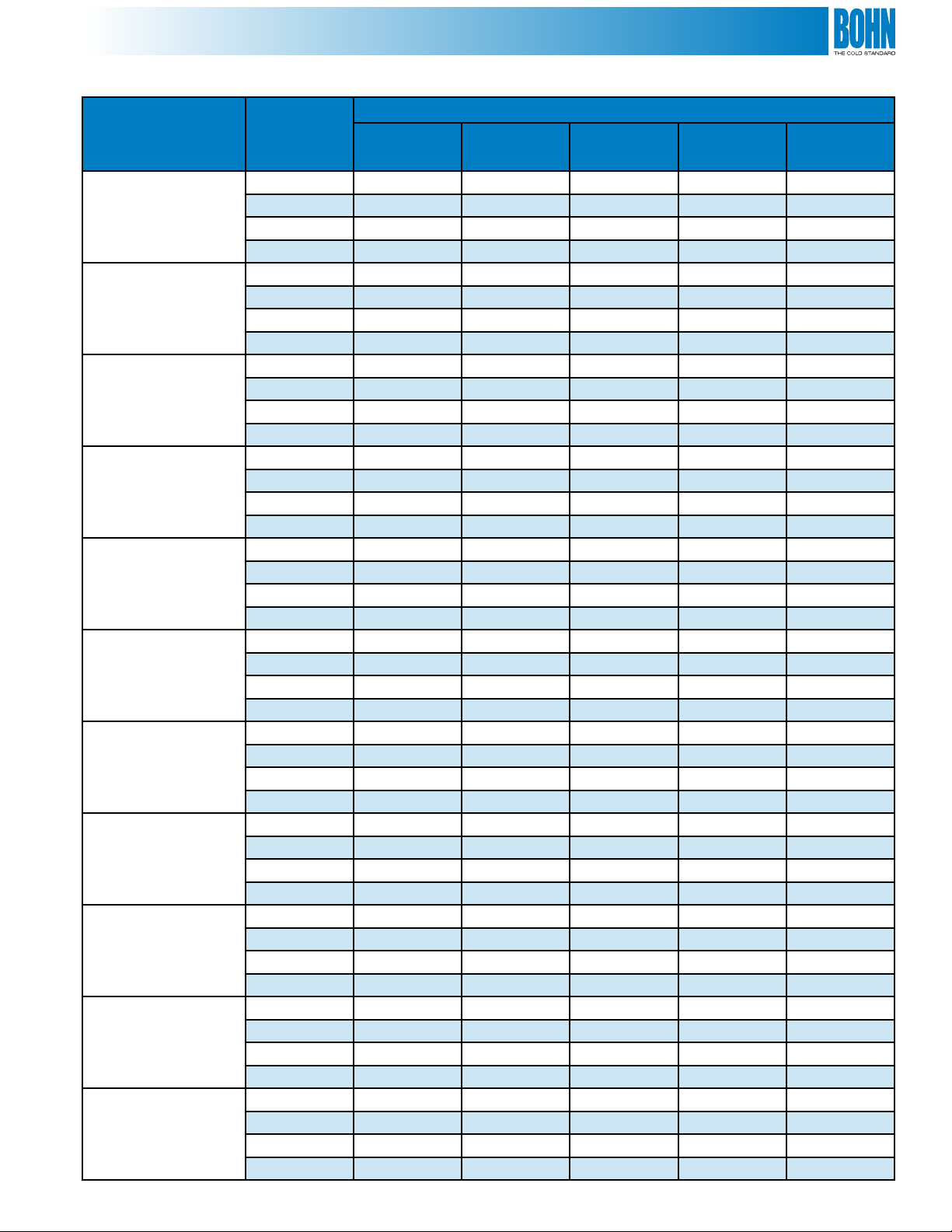
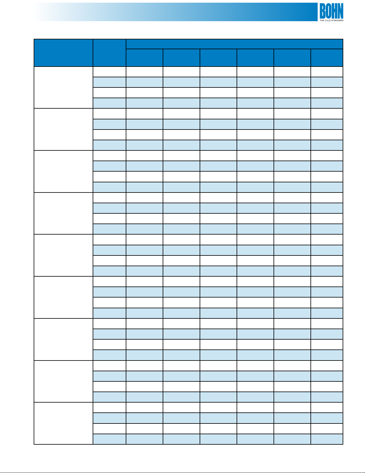
Performance Data • Model BDV • Medium Temperature
Saturated Suction Temperature °F
R-404A or R-507
Model BDV
0752M6
0762M6
0802M6
1002M6
1202M6
1502M6
2002M6
2502M6
3002M6
3502M6
4002M6
Ambient
Temp. °F
90 70,900 64,300 57,900 51,700 45,900
95 67,600 61,300 55,300 49,400 43,800
100 64,500 58,500 52,800 47,100 41,600
110 58,300 53,000 47,700 42,400 37,400
90 80,300 73,400 66,600 60,000 53,600
95 76,800 70,100 63,500 57,300 51,000
100 73,100 66,800 60,700 54,600 48,700
110 66,200 60,600 54,900 49,200 43,700
90 94,300 86,000 77,900 70,200 62,700
95 90,500 82,600 74,900 67,500 60,000
100 86,800 79,200 71,800 64,400 57,500
110 79,000 72,400 65,700 59,000 52,500
90 114,800 104,900 95,100 85,800 76,800
95 110,100 100,600 91,300 82,200 73,400
100 105,300 96,200 87,400 78,600 70,000
110 95,700 87,500 79,300 71,200 63,200
90 138,300 126,500 115,100 103,800 92,800
95 132,500 121,200 110,300 99,400 88,800
100 126,600 116,100 105,400 95,000 84,800
110 115,100 105,400 95,700 86,200 76,600
90 153,300 140,300 127,600 115,000 102,900
95 146,800 134,300 122,200 110,200 98,500
100 140,300 128,700 116,900 105,300 94,000
110 127,500 116,800 106,100 95,600 85,100
90 162,500 147,300 132,900 119,300 106,000
95 154,200 140,100 126,500 113,200 100,400
100 146,400 133,100 119,900 107,100 94,800
110 131,000 118,600 106,500 94,700 83,300
90 212,900 193,000 174,000 156,200 139,400
95 203,800 184,600 166,500 149,000 132,800
100 194,700 176,100 158,600 141,800 126,200
110 176,800 159,600 143,100 127,400 112,600
90 249,200 227,500 206,500 185,600 165,500
95 238,100 217,300 197,200 177,100 157,800
100 226,900 207,400 187,900 168,600 150,000
110 205,000 186,900 169,100 151,500 134,500
90 312,300 285,400 259,300 234,400 209,600
95 297,800 272,700 248,300 223,600 200,000
100 284,000 260,400 236,600 212,900 189,800
110 256,900 235,000 213,200 191,400 169,900
90 359,700 329,700 300,600 272,000 244,200
95 345,100 315,900 287,400 259,800 232,900
100 329,600 301,500 274,300 247,500 221,600
110 298,200 272,700 247,400 222,600 198,600
25°F
BTUH
20°F
BTUH
15°F
BTUH
10°F
BTUH
5°F
BTUH
7
Page 8
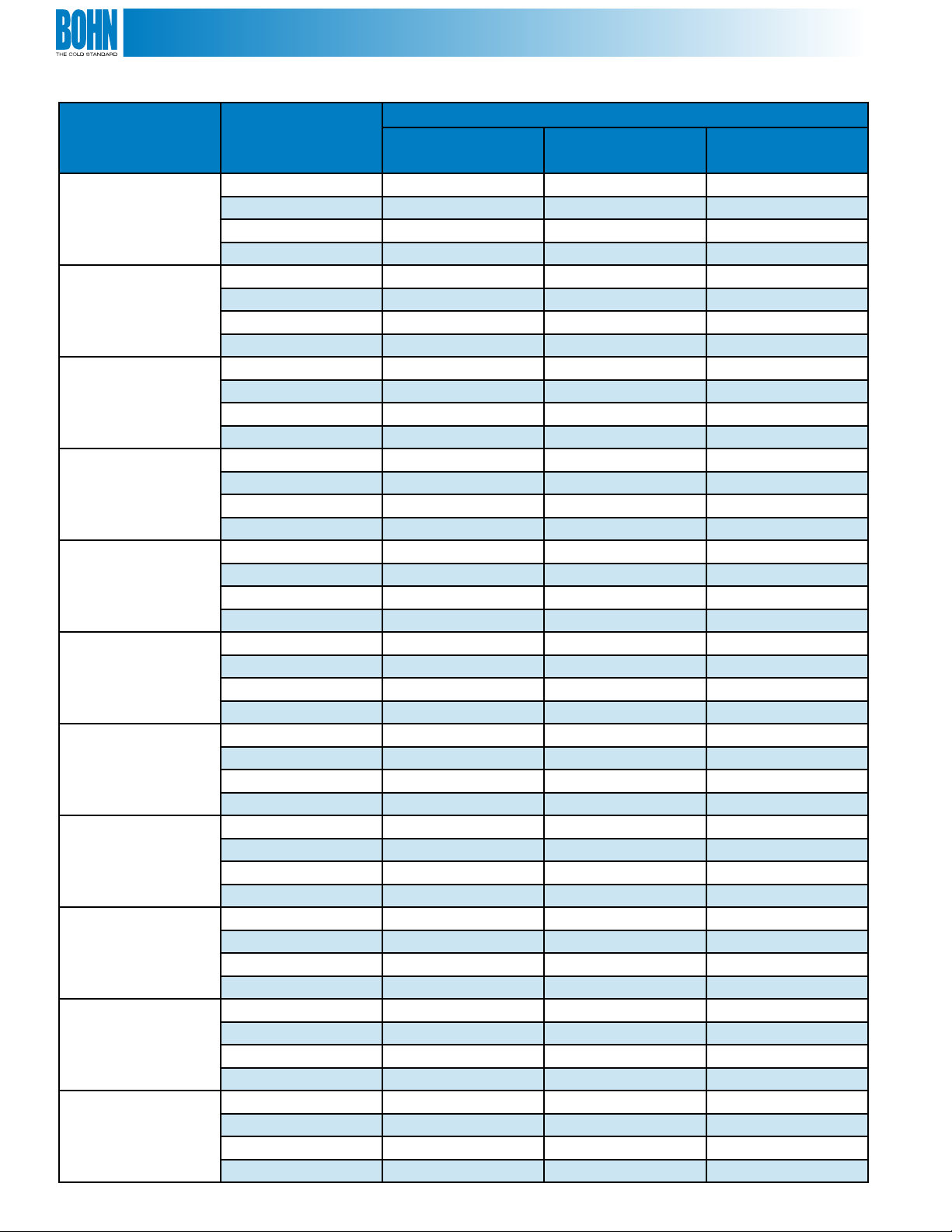
Performance Data • Model BDV • Medium Temperature
Saturated Suction Temperature °F
R-22
Model BDV
0752M6
0762M6
0802M6
1002M6
1202M6
1502M6
2002M6
2502M6
3002M6
3502M6
4002M6
Ambient
Temp. °F
90 68,500 61,900 55,600
95 66,100 59,700 53,600
100 63,700 57,400 51,500
110 58,900 53,000 47,300
90 76,600 69,400 62,600
95 73,700 66,800 60,300
100 71,100 64,300 57,900
110 65,600 59,200 53,200
90 93,000 84,200 75,900
95 89,900 81,300 73,200
100 86,800 78,400 70,400
110 80,600 72,600 65,000
90 111,900 101,500 91,400
95 108,200 98,000 88,100
100 104,600 94,500 84,800
110 97,100 87,500 78,200
90 125,800 113,600 102,000
95 121,700 109,700 98,300
100 117,500 105,700 94,700
110 109,000 97,900 87,400
90 142,400 128,000 114,600
95 137,600 123,700 110,500
100 132,800 119,300 106,500
110 123,500 110,600 98,500
90 157,500 143,000 129,100
95 151,800 137,500 123,900
100 146,200 132,100 118,700
110 135,000 121,400 108,400
90 205,000 186,900 169,600
95 198,100 180,100 163,200
100 191,000 173,300 156,800
110 176,700 159,900 144,000
90 241,500 219,600 198,300
95 233,500 211,800 190,900
100 225,200 203,900 183,500
110 208,500 188,200 168,800
90 295,100 268,700 243,200
95 285,300 259,000 234,100
100 274,900 249,400 225,000
110 254,200 230,100 207,100
90 342,300 312,700 284,600
95 331,200 302,100 274,700
100 320,100 291,600 264,800
110 297,900 270,800 244,900
25°F
BTUH
20°F
BTUH
15°F
BTUH
8
Page 9
Performance Data • Model BDV • Low Temperature
Saturated Suction Temperature °F
R-404A or R-507
Model BDV
Ambient
Temp. °F
90 55,500 44,800 39,800 35,100 26,900 20,400
0°F
BTUH
-10°F
BTUH
-15°F
BTUH
-20°F
BTUH
-30°F
BTUH
-40°F
BTUH
0602L6
0752L6
0902L6
1002L6
1202L6
95 53,000 42,700 37,900 33,400 25,400 19,000
100 50,500 40,600 36,000 31,600 23,900 17,600
110 45,400 36,500 32,200 28,200 20,900 14,900
90 64,200 52,000 46,300 40,900 31,400 23,900
95 61,300 49,700 44,100 38,900 29,700 22,300
100 58,400 47,300 42,000 37,000 28,000 20,700
110 52,600 42,600 37,700 33,100 24,600 17,400
90 78,600 63,600 56,600 50,000 38,400 29,200
95 75,200 60,800 54,000 47,700 36,300 27,400
100 71,900 58,000 51,400 45,300 34,300 25,500
110 65,100 52,400 46,300 40,500 30,300 21,800
90 86,000 70,400 62,700 55,700 43,000 32,800
95 82,300 67,100 59,800 53,000 40,700 30,600
100 78,700 64,000 57,000 50,300 38,300 28,500
110 71,600 57,800 51,300 45,000 33,700 24,200
90 89,100 73,000 64,900 57,400 43,900 32,900
95 84,900 69,400 61,800 54,500 41,300 30,300
100 80,800 66,000 58,800 51,700 38,700 27,800
1502L6
2202L6
2702L6
3002L6
110 72,400 59,300 52,600 46,100 33,600 22,400
90 117,500 96,600 86,700 77,300 60,000 45,500
95 112,100 92,100 82,500 73,400 56,700 42,600
100 106,800 87,600 78,300 69,600 53,500 39,800
110 95,900 78,500 70,100 61,900 47,100 34,100
90 139,400 115,800 103,700 92,400 71,500 52,400
95 132,200 109,500 98,300 87,400 67,100 49,500
100 125,000 103,500 92,800 82,400 62,800 45,600
110 110,500 91,500 81,900 72,400 54,200 37,800
90 175,500 144,100 128,300 113,700 87,400 65,500
95 167,400 136,800 122,100 107,900 82,300 60,900
100 159,900 130,000 115,900 102,200 77,300 56,200
110 143,500 116,300 103,300 90,700 67,200 47,100
90 192,900 158,100 141,400 125,300 96,700 73,600
95 183,400 150,200 134,100 118,700 90,800 68,200
100 173,900 142,300 126,900 112,200 84,900 62,600
110 154,700 126,300 112,300 98,500 73,400 51,800
9
Page 10

Specications and Dimensions • Model BDV
Model
BDV Compressor
0752M6
0762M6
0802M6
1002M6
1202M6
1502M6
2002M6
2502M6
3DA3A075E 2 24” 5/8 1-5/8 93 / 81 A 1650
3DB3A100E 2 26” 5/8 1-5/8 93 / 81 B 1725
3DF3A120E 2 26” 7/8 2-1/8 93 / 81 B 1750
3DS3A150E 2 30” 7/8 2-1/8 142 / 123 C 1780
4DA3A200E 2 30” 7/8 2-1/8 142 / 123 C 1860
4DH3A250E 3 30” 1-1/8 2-1/8 142 / 123 D 1950
Condenser
Fan Data Connections
No.
Fans Dia. Liquid Suction
2DL3-075E 2 24” 5/8 1-3/8 93 / 81 A 1550
2DA3-075E 2 24” 5/8 1-3/8 93 / 81 A 1550
Receiver
(90% Full)
R-22/R404A
Lbs.
Dim. Info.
See Figure
Approx.
Net
Weight
Lbs.
3002M6
3502M6
4002M6
0602L6
0752L6
0902L6
1002L6
1202L6
1502L6
2202L6
4DJ3A300E 3 30” 1-1/8 2-1/8 216 / 188 D 1950
6DH3A350E 3 30” 1-1/8 2-1/8 216 / 188 D 2800
6DJ3A400E 4 30” 1-1/8 2-1/8 216 / 188 E 3000
3DA3A060E 2 24” 5/8 1-3/8 81 A 1600
3DB3A075E 2 24” 5/8 1-3/8 81 A 1600
3DF3A090E 2 24” 5/8 1-5/8 81 A 1650
3DS3A100E 2 24” 5/8 1-5/8 81 A 1650
4DA3A101E 2 24” 5/8 1-5/8 81 A 1700
4DL3A150E 2 26” 7/8 2-1/8 81 B 1850
4DT3A220E 2 30” 7/8 2-1/8 81 C 2120
2702L6
3002L6
10
6DL3A270E 2 30” 1-1/8 2-1/8 123 C 2180
6DT3A300E 2 30” 1-1/8 2-1/8 123 C 2200
Page 11
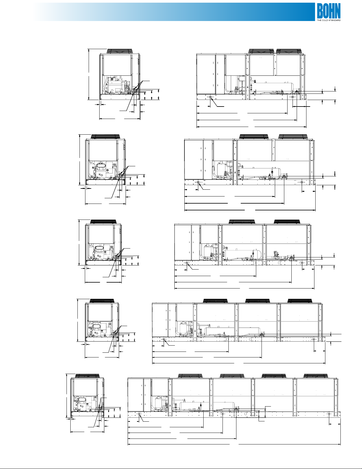
Dimensions (Inches) • Model BDV
A
B
C
1.76
FRAME C/L
55.5
55.5
55.5
1.76
FRAME C/L
O 2.50 K.O.
O 2.50 K.O.
44.5
44.50
6.66
6.64
O 1.38 X 1.75 K.O.
10.14
8.4 6
4.03
O 1.38 X 1.75 K.O.
O 1.38 X 1.75 K.O.
10.14
8.46
4.02
11.58
11.58
15.00
15.00
O 3.00
O 3.00
99.3 4
LIQUID
109.48
SUCTION
99.2 2
LIQUID
109.57
SUCTION
120
144.00
15.00
15.00
6.56
LIQUID
7.4 1
LIQUID
9.27
SUCTION
9.70
SUCTION
D
E
57.5
55.5
1.76
FRAME C/L
O 2.50 K.O.
1.76
FRAME C/L
O 2.50 K.O.
1.76
FRAME C/L
O 2.50 K.O.
44.7
44.5
44.5
10.46
6.73
6.66
8.46
6.66
O 1.38 X 1.7 5 K.O.
13.58
12.14
4.10
10.14
8.4 6
4.03
O 1.38 X 1.75 K.O.
11.58
10.14
4.03
15.00
11.58
O 3.00
15.00
99.50
LIQUID
125.00
15.00
O 3.00
142.73
SUCTION
99.50
LIQUID
O 3.00
142.75
SUCTION
99.34
LIQUID
142.74
SUCTION
280.0 5
225.67
170.68
9.41
LIQUID
11.70
LIQUID
15.00
LIQUID
15.00
7.4 1
9.70
SUCTION
7.41
LIQUID
15.00
11
Page 12

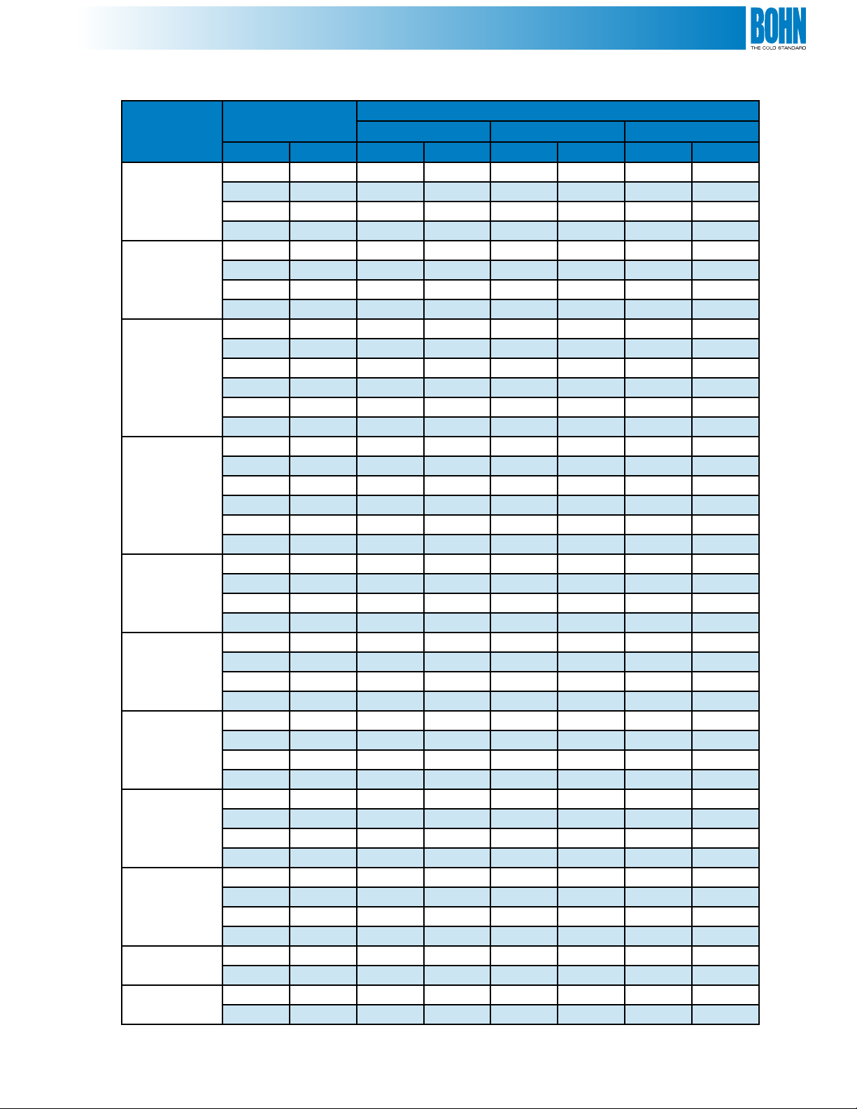
Electrical Data • Model BDV
208-230 Volts
Independent (STD)
Compressor
System Power
Cond.
Model
BDV Compressor
0752M6 2DL3-075E 28.3 169 2 5.2 40.6 60 7.8 48.4 70
0762M6 2DA3-075E 28.7 169 2 5.2 41.1 60 7.8 48.9 70
0802M6 3DA3A075E 36.8 215 2 5.2 51.2 80 10.4 61.6 90
1002M6 3DB3A100E 39.1 215 2 9.6 58.5 90 13.8 72.3 110
1202M6 3DF3A120E 43.2 275 2 9.6 63.6 100 13.8 77.4 110
1502M6 3DS3A150E 53.5 275 2 14.0 80.9 125 19.8 100.7 150
2002M6 4DA3A200E 59.7 308 2 14.0 88.6 125 21.0 109.6 150
2502M6 4DH3A250E 73.7 428 3 21.0 113.1 175 27.6 140.7 200
3002M6 4DJ3A300E 84.4 470 3 21.0 126.5 200 39.6 166.1 250
3502M6 6DH3A350E 96.2 565 3 21.0 141.3 225 42.0 183.3 250
4002M6 6DJ3A400E 126.9 594 4 28.0 186.6 300 56.0 242.6 350
0602L6 3DA3A060E 24.0 150 2 5.2 35.2 50 12.0 47.2 70
0752L6 3DB3A075E 27.6 161 2 5.2 39.7 60 18.0 57.7 80
0902L6 3DF3A090E 33.2 215 2 5.2 46.7 80 24.0 70.7 100
1002L6 3DS3A100E 37.2 215 2 5.2 51.7 80 24.0 75.7 110
1202L6 4DA3A101E 40.9 220 2 5.2 56.3 90 24.0 80.3 110
1502L6 4DL3A150E 47.2 278 2 9.6 68.6 110 24.6 93.2 125
2202L6 4DT3A220E 57.7 374 2 14.0 86.1 125 24.6 110.7 150
2702L6 6DL3A270E 72.4 450 2 14.0 104.5 175 24.6 129.1 200
3002L6 6DT3A300E 85.8 470 2 14.0 121.3 200 24.6 145.9 225
*230/6/60 MCA = Minimum Circuit Ampacity MOP = Maximum Overcurrnent Protection
RLA LRA MCA MOP
No.
Fans
Fan
FLA
Evap Powered From
Condensing Unit
Evap
Max
Amps MCA MOP
Independent Vs. Single Power Supplies
Independent Power Supplies for Condensing
Units and Unit Coolers (Std)
• In this option, a separate high voltage power
supply is run to each evaporator and the
condensing unit
• Low voltage control wiring is run between
the condensing unit and each evaporator
(including evaporator sensor, liquid solenoid
and evaporator control contactor(s)
Single Power Supply for Condensing Unit
Providing Power to Unit Coolers
• In this option, a power supply is run to the
condensing unit and high voltage wiring is
run from the condensing unit to power the fan
motor and drain pan heaters in each evaporator
• Low voltage control wiring is run between the
condensing unit and each evaporator for the
evaporator sensor and liquid solenoid
12
Advantages
• Electrician can run simple point-to-point power supplies without having to
understand the control circuit wiring
• Evaporator disconnect switch wiring is simplied (if required)
• Refrigeration contractors can generally run the low voltage wiring with
the refrigeration piping and make these wiring connections with a good
understanding of the control circuit function
• The condensing unit wire size and fusing requirements are minimized
because they don’t include a worst-case remote evaporator load
• Lower cost installation solution
Advantages
• A benet for retrot situations if there is existing control wiring that can be
employed
• In applications where there is limited evaporator accessibility (ex: controlled
atmosphere rooms)
Page 13

Electrical Data • Model BDV
460 Volts
Independent (STD)
Compressor
System Power
Cond.
Model
BDV Compressor
0752M6 2DL3-075E 12.4 85 2 2.6 18.1 30 3.0 21.1 30
0762M6 2DA3-075E 12.6 85 2 2.6 18.4 30 3.0 21.4 30
0802M6 3DA3A075E 17.9 106 2 2.6 25 40 4.7 29.7 45
1002M6 3DB3A100E 17.9 106 2 4.8 27.2 45 6.9 34.1 50
1202M6 3DF3A120E 21.2 138 2 4.8 31.3 50 6.9 38.2 50
1502M6 3DS3A150E 26.0 138 2 7.0 39.5 60 9.9 49.4 70
2002M6 4DA3A200E 29.9 154 2 7.0 44.4 70 10.5 54.9 80
2502M6 4DH3A250E 36.9 214 3 10.5 56.6 90 13.8 70.4 100
3002M6 4DJ3A300E 42.2 235 3 10.5 63.3 100 19.8 83.1 125
3502M6 6DH3A350E 48.1 283 3 10.5 70.6 110 21.0 91.6 125
4002M6 6DJ3A400E 63.5 297 4 14.0 93.4 150 28.0 121.4 175
0602L6 3DA3A060E 10.8 77 2 2.6 16.1 25 6.0 22.1 30
0752L6 3DB3A075E 14.1 83 2 2.6 20.2 30 9.0 29.2 40
0902L6 3DF3A090E 15.0 106 2 2.6 21.4 35 12.0 33.4 45
1002L6 3DS3A100E 16.7 106 2 2.6 23.5 40 12.0 35.5 50
1202L6 4DA3A101E 20.4 110 2 2.6 28.1 45 12.0 40.1 60
1502L6 4DL3A150E 23.6 139 2 4.8 34.3 50 12.3 46.6 70
2202L6 4DT3A220E 28.8 187 2 7.0 43 70 12.3 55.3 80
2702L6 6DL3A270E 36.2 225 2 7.0 52.3 80 12.3 64.6 100
3002L6 6DT3A300E 42.9 235 2 7.0 60.6 100 12.3 72.9 110
MCA = Minimum Circuit Ampacity MOP = Maximum Overcurrent Protection
RLA LRA MCA MOP
No.
Fans
Fan
FLA
All selection require 3 phase power supply.
Evap Powered From
Condensing Unit
Evap
Max
Amps MCA MOP
Independent Vs. Single Power Supplies
Independent Power Supplies for Condensing
Units and Unit Coolers (Std)
• In this option, a separate high voltage power
supply is run to each evaporator and the
condensing unit
• Low voltage control wiring is run between
the condensing unit and each evaporator
(including evaporator sensor, liquid solenoid
and evaporator control contactor(s)
Single Power Supply for Condensing Unit
Providing Power to Unit Coolers
• In this option, a power supply is run to the
condensing unit and high voltage wiring is
run from the condensing unit to power the fan
motor and drain pan heaters in each evaporator
• Low voltage control wiring is run between the
condensing unit and each evaporator for the
evaporator sensor and liquid solenoid
Advantages
• Electrician can run simple point-to-point power supplies without having to
understand the control circuit wiring
• Evaporator disconnect switch wiring is simplied (if required)
• Refrigeration contractors can generally run the low voltage wiring with
the refrigeration piping and make these wiring connections with a good
understanding of the control circuit function
• The condensing unit wire size and fusing requirements are minimized
because they don’t include a worst-case remote evaporator load
• Lower cost installation solution
Advantages
• A benet for retrot situations if there is existing control wiring that can be
employed
• In applications where there is limited evaporator accessibility (ex: controlled
atmosphere rooms)
13
Page 14

Hot Gas Unit Cooler Typical Factory Piping
Note: Control contactors
mount under a cover
Electrical
Connections
(this side)
on front of unit (not shown)
Air
Flow
Suction
Connection
Liquid
Connection
Liquid
Solenoid
Valve
Check
Valve
Suction
P-Trap
Hot Gas
D
rain Pan
Shown
Thermostatic
Expansion
Valve
Check
Valves
14
Page 15

Medium Prole Hot Gas Defrost Unit Coolers
for use with the Bohn Mohave Hot Gas Defrost System
Standard Features
• Mounted and wired control contactors
• Schrader valve provided for suction pressure measurement
• Permanent split capacitor (PSC), thermally protected, lifetime-lubricated
motors in 115, 208-230 and 460 volts
• All internal panels have been “isolated” which provides for quiet
unit operation
• Motors plug into wiring harness for easier servicing
• Factory mounted liquid line solenoid valve, TXV, and distributor nozzle
• Electric drain pan heaters
• Four and six FPI coils
• Single point power supply
• Suction “P” trap
• Insulated drain pan on low temp systems
Options
• UL approved totally enclosed motors
• EC motors (optional) available factory-installed or as a drop-in replacement through InterLink™ Commercial
Refrigeration Parts in 115/1/60, 208-230/1/60 voltages
• Available in stainless steel cabinets and/or drain pan*
• Copper n or coil coatings (Electron, and BohnGuard™)
• Mounted hot gas drain pan loop
• Evaporator control contactors mounted in condensing unit
• Insulated drain pan for medium temp systems
* aluminum inner drain pan with insulated outer stainless steel drain pan
E Solutions™ branded products and options are designed to exceed current energy and environmental
standards. We have made a conscious commitment to developing environmentally innovative products
that allow our customers to make energy ecient, eco-conscious choices. Products included in the
E Solutions portfolio reduce costs, improve bottom lines, and enhance both equipment performance and
service life. Choosing EC motors for this portion of the system decreases energy consumption and increases
energy cost savings.
Nomenclature
BMG (6 FPI), BMF (4 FPI)
Capacity X 100
BMG 190 B G A
Voltage:
A = 115/1/60
B = 208-230/1/60
M = 460/1/60
Vintage Code
Hot Gas System Evaporator
15
Page 16

Medium Prole Unit Coolers
Capacity and Electrical Data
Models BMG/BMF 60 Hz.
BTUH
Hot Gas
Defrost
Model
BMG 260 26,000 4,500 2 18 50 65 1/4 8.0 3.6 2.0 5.6 2.8 9.0 20 4.5 20 2.3 15
BMG 310 31,000 7,050 3 18 50 65 1/4 12.0 5.4 3.0 8.4 4.2 13.0 20 6.0 20 3.3 15
BMG 390 39,000 6,750 3 18 50 65 1/4 12.0 5.4 3.0 8.4 4.2 13.0 20 6.0 20 3.3 15
BMG 430 43,000 8,800 4 18 50 65 1/4 16.0 7.2 4.0 11.2 5.6 17.0 20 8.0 20 4.3 15
BMG 520 52,000 8,400 4 18 50 65 1/4 16.0 7.2 4.0 11.2 5.6 17.0 20 8.0 20 4.3 15
BMF 220 22,000 4,650 2 18 50 65 1/4 8.0 3.6 2.0 5.6 2.8 9.0 20 4.5 20 2.3 15
BMF 250 25,000 7,350 3 18 50 65 1/4 12.0 5.4 3.0 8.4 4.2 13.0 20 6.0 20 3.3 15
BMF 330 33,000 6,975 3 18 50 65 1/4 12.0 5.4 3.0 8.4 4.2 13.0 20 6.0 20 3.3 15
BMF 370 37,000 9,100 4 18 50 65 1/4 16.0 7.2 4.0 11.2 5.6 17.0 20 8.0 20 4.3 15
BMF 440 44,000 8,700 4 18 50 65 1/4 16.0 7.2 4.0 11.2 5.6 17.0 20 8.0 20 4.3 15
*Standard molded fan guards allow for extended air throw; optional wire guards promote air diusion
† Air throw data based on 12-ft. high ceilings with no obstructions where velocity drops to 50 FPM
†† Data appropriate for electric and hot gas defrost drain pan
MCA = Minimum Circuit Ampacity MOP = Maximum Overcurrent Protection
10°F.
TD
-20°F.
SST
CFM
Fan Data Motor Data (Total Amps) Electrical Supply Requirements
No.
*†Air Throw (Ft.)
Dia.
Diused
(In.)
(Std.)
Extended
(Opt.)
HP
BMG (6 FPI MODELS)
BMF (4 FPI MODELS)
PSC Motor EC Motor 115V 208-230V 460V
115/
1/60
208230/
1/60
460/
1/60
115/
1/60
208230/
1/60
MCA MOP MCA MOP MCA MOP
††
Physical Data
Hot Gas Defrost Physical Data
Model
BMG 260 2 6 1/2 1-3/8 ODF 216
BMG 310 3 6 1/2 1-3/8 ODF 242
BMG 390 3 6 1/2 1-3/8 ODF 269
BMG 430 4 6 1/2 1-5/8 ODF 312
BMG 520 4 6 1/2 1-5/8 ODF 345
BMF 220 2 4 1/2 1-3/8 ODF 214
BMF 250 3 4 1/2 1-3/8 ODF 239
BMF 330 3 4 1/2 1-3/8 ODF 266
BMF 370 4 4 1/2 1-5/8 ODF 307
BMF 440 4 4 1/2 1-5/8 ODF 340
No. of
Fans FPI
MLG6 (6 FPI Models)
MLG4 (4 FPI Models)
Connections (Inches) Approximate
Net Weight
(lbs.)Liquid Suction
16
Page 17

Medium Prole Unit Coolers
Dimensional Data
18-7/8"
480 mm
17-1/2"
444 mm
Air
Flow
Refrigerant
Connection
End
608 mm
2-1/2"
64 mm
24"
15-1/2"
390 mm
22-3/4"
578 mm
*Factory piping extends behind the unit cooler and may add up to 6 inches to this dimension.
6 FPI
Models
BMG
BMG260
BMG310
BMG390
BMG430
BMG520
NOTE: Evaporator mounting brackets accept up to 1/2" hanger rod
4 FPI
Models
Hot
Gas
Hot
Gas
BMF
BMF220 67-5/16 1,710 58-1/4 1,480 - - - - - - 4-15/16 125
BMF250 95-5/16 2,420 86-1/4 2,190 - - - - - - 4-15/16 125
BMF330 95-5/16 2,420 86-1/4 2,190 - - - - - - 4-15/16 125
BMF370 123-5/16 3,130 114-1/4 2,900 56 1,420 58-1/4 1,480 - - 4-15/16 125
BMF440 123-5/16 3,130 114-1/4 2,900 56 1,420 58-1/4 1,480 - - 4-15/16 125
A B C D E F
in. mm in. mm in. mm in. mm in. mm in. mm
Dimensions
23 -1/4"
590 mm
Electrical
Connection
End
17
Page 18

Large Hot Gas Defrost Unit Coolers
for use with the Bohn Mohave Hot Gas Defrost System
Standard Features
• Mill nish aluminum provides an attractive design and
structurally sound cabinet
• Thermo-Flex (with ve-year limited warranty) is innovative,
eliminates leaks, and reduces risk of refrigerant loss
• 850 RPM motors are quiet and reliable
• Liquid line solenoid wiring harness for faster installation
• Suction Schrader tting for easier suction temperature
measurement
• Captive fasteners on access panels for easy servicing
• Long air throw is ideal for large warehouse and industrial applications
• Electric drain pan heater
• Insulated drain pan heater for low temp systems
Optional Features
U
C
US
L
®
• High CFM motor and fan combinations (208-230/3/60 and 460/3/60)
• Totally enclosed motors (208-230/3/60 and 460/3/60)
• Long air throw collars for large warehouse and industrial applications
• More factory mounted features for easier eld installation (Consult factory)
• Evaporator control contactors mounted in condensing unit
• Insulated drain pan for medium temperature systems
• Mounted hot gas drain pan loop
Nomenclature
BHG 850 B P G A
BHG (6 FPI), F (4 FPI)
Optional Motor Code
T = Totally Enclosed Motors
V = High CFM Option
P = 3 Phase Motor
Vintage
Hot Gas System Evap.
18
Capacity x 100
(standard motor/fan blade)
Voltage Code
A = 115/1/60
B = 208-230/1/60
C = 208-230/3/60
D = 460/3/60
M = 460/1/60
Page 19

Large Unit Coolers
Hot Gas Defrost Capacity & Electrical Data - 60Hz.
Fan Data Standard Motor Data
Dia.
(In.)
Air Throw (Ft.)
with
Std.
Collar
HP
208-230/1/60
Wired
Wired
1
Phase
Phase
6 FPI MODELS
4 FPI MODELS
3
— 19.8 — — 9.9 21.5 40 10.7 20
BTUH
Hot Gas
Defrost
Model
BHG 450 45,000 9,000 2 24 70 85 1/2+ 6.4 — 5.2 3.4 — 2.6 9.2 20 4.6 15
BHG 550 55,000 9,000 2 24 70 85 1/2+ 6.4 — 5.2 3.4 — 2.6 9.2 20 4.6 15
BHG 640 64,000 12,600 3 24 70 85 1/2+ — 5.5 7.8 — 3.0 3.9 12.0 20 5.9 15
BHG 740 74,000 12,600 3 24 70 85 1/2+ — 5.5 7.8 — 3.0 3.9 12.0 20 5.9 15
BHG 810 81,000 16,800 4 24 70 85 1/2+ — 8.7 10.4 — 4.7 5.2 18.0 20 8.7 15
BHG 950 95,000 16,800 4 24 70 85 1/2+ — 8.7 10.4 — 4.7 5.2 18.0 20 8.7 15
BHG 1020 102,000 20,700 3 30 100 115 1 — — 13.8 — — 6.9 18.0 25 8.7 15
BHG 1200 120,000 20,700 3 30 100 115 1 — — 13.8 — — 6.9 18.0 25 8.7 15
BHG 1390 139,000 24,300 3 30 100 115 1-1/2 — — 19.8 — — 9.9 21.5 40 10.7 20
BHG 1650 165,000 26,550 3 30 120 140 1-1/2 — — 21.0 — — 10.5 22.8 40 11.4 20
BHG 2120 212,000 35,400 4 30 120 140 1-1/2 — — 28.0 — — 14.0 29.9 45 14.9 25
BHF 400 40,000 9,400 2 24 70 85 1/2+ 6.4 — 5.2 3.4 — 2.6 9.2 20 4.6 15
BHF 480 48,000 9,400 2 24 70 85 1/2+ 6.4 — 5.2 3.4 — 2.6 9.2 20 4.6 15
BHF 560 56,000 13,200 3 24 70 85 1/2+ — 5.5 7.8 — 3.0 3.9 12.0 20 5.9 15
BHF 650 65,000 13,200 3 24 70 85 1/2+ — 5.5 7.8 — 3.0 3.9 12.0 20 5.9 15
BHF 710 71,000 17,600 4 24 70 85 1/2+ — 8.7 10.4 — 4.7 5.2 18.0 20 8.7 15
BHF 840 84,000 17,600 4 24 70 85 1/2+ — 8.7 10.4 — 4.7 5.2 18.0 20 8.7 15
BHF 890 89,000 21,600 3 30 100 115 1 — — 13.8 — — 6.9 18.0 25 8.7 15
BHF 1050 105,000 21,600 3 30 100 115 1 — — 13.8 — — 6.9 18.0 25 8.7 15
BHF 1220 122,000 25,200 3 30 100 115 1-1/2 —
BHF 1440 144,000 27,600 3 30 120 140 1-1/2 — — 21.0 — — 10.5 22.8 40 11.4 20
BHF 1860 186,000 36,800 4 30 120 140 1-1/2 — — 28.0 — — 14.0 29.9 45 14.9 25
†
Data appropriate for electric and hot gas defrost drain pan
10°F.
TD
-20°F.
SST
Std.
CFM No.
Total Amps
208-
230/3/60
460/1/60
Wired
Wired
1
3
Phase
460/3/60
Phase MCA MOPD MCA MOP
Electrical Supply
Requirements
208-230V 460V
†
Note: TD = Temperature Dierence = (Room temperature - saturated suction temperature)
MCA = Minimum Circuit Ampacity MOP = Maximum Overcurrent Protection
Capacity Correction Factors for Electric and Hot Gas Defrost Units
Saturated Suction Temperature °F +20 -10 -20 -30 -40
Saturated Suction Temperature °C -7 -23 -29 -34 -40
Multiply Capacity By 1.15 1.04 1.00 0.90 0.80
19
Page 20

Large Unit Coolers
Hot Gas Defrost High CFM Capacity & Electrical Data - 60Hz.
BTUH
10°F.
Hot Gas
Defrost
Model
BHG 450*V 49,500 11,300 2 24 85 100 2 12.0 6.0
BHG 550*V 60,500 11,300 2 24 85 100 2 12.0 6.0
BHG 640*V 70,400 15,900 3 24 85 100 2 18.0 9.0
BHG 740*V 81,400 15,900 3 24 85 100 2 18.0 9.0
BHG 810*V 89,100 21,200 4 24 85 100 2 24.0 12.0
BHG 950*V 104,000 21,200 4 24 85 100 2 24.0 12.0
BHG 1020*V 107,100 23,300 3 30 110 130 3 24.6 12.3
BHG 1200*V 126,000 23,300 3 30 110 130 3 24.6 12.3
BHG 1390*V 146,000 27,200 3 30 110 130 3 24.6 12.3
BHG 1650*V 174,000 29,700 3 30 130 150 3 24.6 12.3
BHG 2120*V 223,000 39,600 4 30 130 150 3 32.8 16.4
BHF 400*V 42,000 12,200 2 24 85 100 2 12.0 6.0
BHF 480*V 50,400 12,200 2 24 85 100 2 12.0 6.0
BHF 560*V 58,800 17,000 3 24 85 100 2 18.0 9.0
BHF 650*V 68,300 17,000 3 24 85 100 2 18.0 9.0
BHF 710*V 74,600 22,600 4 24 85 100 2 24.0 12.0
BHF 840*V 88,200 22,600 4 24 85 100 2 24.0 12.0
BHF 890*V 91,200 23,800 3 30 110 130 3 24.6 12.3
BHF 1050*V 107,600 23,800 3 30 110 130 3 24.6 12.3
BHF 1220*V 125,000 32,800 3 30 110 130 3 24.6 12.3
BHF 1440*V 147,000 30,600 3 30 130 150 3 24.6 12.3
BHF 1860*V 190,000 40,800 4 30 130 150 3 32.8 16.4
†
Data appropriate for electric and hot gas defrost drain pan.
Note: TD = Temperature Dierence = (Room temperature - saturated suction temperature)
MCA = Minimum Circuit Ampacity MOP = Maximum Overcurrent Protection
High CFM models can handle external static pressure up to 1/2” of water
High CFM models are designed for operation below +15°F S.S.T.
CFM is at 0.0 external static pressure
TD
-20°F.
SST
Std.
CFM No.
Fan Data Standard Motor Data
Dia.
(In.)
Air Throw (Ft.)
with
Std.
Collar 208-230/3/60 460/3/60
6 FPI MODELS
4 FPI MODELS
HP
Total Amps
Electrical Supply
Requirements
208-230V 460V
MCA MOP MCA MOP
13.5 30 6.8 15
13.5 30 6.8 15
19.5 35 9.8 15
19.5 35 9.8 15
25.5 40 12.8 20
25.5 40 12.8 20
26.7 45 13.3 25
26.7 45 13.3 25
26.7 45 13.3 25
26.7 45 13.3 25
34.9 50 17.4 25
13.5 30 6.8 15
13.5 30 6.8 15
19.5 35 9.8 15
19.5 35 9.8 15
25.5 40 12.8 20
25.5 40 12.8 20
26.7 45 13.3 25
26.7 45 13.3 25
26.7 45 13.3 25
26.7 45 13.3 25
34.9 50 17.4 25
†
Capacity Correction Factors for Electric and Hot Gas Defrost Units
Saturated Suction Temperature °F +20 -10 -20 -30 -40
Saturated Suction Temperature °C -7 -23 -29 -34 -40
Multiply Capacity By 1.15 1.04 1.00 0.90 0.80
20
Page 21

Large Unit Coolers
Physical Specications - Hot Gas Defrost
Hot Gas
Defrost
Model Size No. of Fans
BHG 450 2 5/8 OD 1-5/8 OD 1-1/4 FPT 320
BHG 550 2 5/8 OD 1-5/8 OD 1-1/4 FPT 350
BHG 640 3 5/8 OD 2-1/8 OD 1-1/4 FPT 458
BHG 740 3 5/8 OD 2-1/8 OD 1-1/4 FPT 498
BHG 810 4 5/8 OD 2-1/8 OD 1-1/4 FPT 597
BHG 950 4 5/8 OD 2-1/8 OD 1-1/4 FPT 647
BHG 1020 3 5/8 OD 2-1/8 OD 1-1/4 FPT 842
BHG 1200 3 7/8 OD 2-1/8 OD 1-1/4 FPT 904
BHG 1390 3 7/8 OD 2-1/8 OD 1-1/4 FPT 958
BHG 1650 3 1-1/8 OD 2-5/8 OD 1-1/4 FPT 1291
Connections (Inches)
Approx. Net
Weight (Lbs.)Liquid Suction Drain
6 FPI MODELS
BHG 2120 4 1-1/8 OD 2-5/8 OD 1-1/4 FPT 1781
4 FPI MODELS
BHG 400 2 5/8 OD 1-5/8 OD 1-1/4 FPT 317
BHG 480 2 5/8 OD 1-5/8 OD 1-1/4 FPT 346
BHG 560 3 5/8 OD 2-1/8 OD 1-1/4 FPT 453
BHG 650 3 5/8 OD 2-1/8 OD 1-1/4 FPT 493
BHG 710 4 5/8 OD 2-1/8 OD 1-1/4 FPT 590
BHG 840 4 5/8 OD 2-1/8 OD 1-1/4 FPT 640
BHG 890 3 5/8 OD 2-1/8 OD 1-1/4 FPT 833
BHG 1050 3 7/8 OD 2-1/8 OD 1-1/4 FPT 894
BHG 1220 3 7/8 OD 2-1/8 OD 1-1/4 FPT 947
BHG 1440 3 1-1/8 OD 2-5/8 OD 1-1/4 FPT 1276
BHG 1860 4 1-1/8 OD 2-5/8 OD 1-1/4 FPT 1761
21
Page 22

Large Unit Coolers
Dimensions
Figure 1.
26 1/
4
24 1/
4
6 7/
A
8
B
8
C
G
4 9/
16
Factory piping extends behind the unit cooler and may add up to 6 inches to this dimension
*
21 5/
29 1/
32
*
2
Refrigerant
Piping End
Hot Gas Defrost
Models Dimensions (Inches)
6 FPI 4 FPI Figure A B C F G
BHG 450 BHF 400 1 83-3/32 68-1/8 —- 37-3/16 40-11/32
BHG 550 BHF 480 1 83-3/32 68-1/8 —- 37-3/16 40-11/32
BHG 640 BHF 560 1 105-5/32 90-3/16 45-3/32 37-3/16 40-11/32
BHG 740 BHF 650 1 105-5/32 90-3/16 45-3/32 37-3/16 40-11/32
BHG 810 BHF 710 1 135-7/32 120-1/4 60-1/8 37-3/16 40-11/32
Accepts
1
/2” Hanger Rod
F
Electrical
End
BHG 950 BHF 840 1 135-7/32 120-1/4 60-1/8 37-3/16 40-11/32
22
Page 23

Large Unit Coolers
Dimensions
Figure 2.
A
B
E
35 21/
34
32
79/
16
C
D
G
3
/
23
4
7
/
4
16
32
413/
*
32
Refrigerant
Piping End
Accepts 5/8” Hanger Rod
*Factory piping extends behind the unit cooler and may add up to 6 inches to this dimension
Hot Gas Defrost Models Dimensions (Inches)
6 FPI 4 FPI Fig. A B C D E F G
BHG 1020 BHF 890 2 135-13/32 120-9/32 40-3/32 80-3/16 — 44-1/2 50-5/16
BHG 1200 BHF 1050 2 135-13/32 120-9/32 40-3/32 80-3/16 — 44-1/2 50-5/16
BHG 1390 BHF 1220 2 135-13/32 120-9/32 40-3/32 80-3/16 — 50-7/32 55-13/16
BHG 1650 BHF 1440 2 142-1/2 127-25/32 42-19/32 85-3/16 — 50-7/32 55-13/16
— — 2 185-1/2 170-3/8 42-19/32 85-3/16 127-25/32 44-1/2 50-5/16
BHG 2120 BHF 1860 2 185-1/2 170-3/8 42-19/32 85-3/16 127-25/32 50-7/32 56-1/4
Electrical
End
F
Air Throw
Hot Gas Defrost Models
Air
Standard
Motor
RPM
Standard
HP Each
Air
Throw
Throw
with
Collar
450 - 950 400 - 840 850 1/2+ 70 85 1750 2 80 100
1020 - 1390 890 - 1220 850 1 & 1-1/2 100 120 1750 3 115 145
1650 - 2120 1440 - 1860 1140 1-1/2 120 145 1750 3 130 150
+ Three Phase Motors are 1140 RPM
Air throw data based on 30 ft. ceiling height with no obstructions where velocity drops to 50 FPM
Optional
High
CFM
Motor
RPM
Optional
HP Each
Air
Throw
Air
Throw
with
Collar6 FPI 4 FPI
23
Page 24

Mohave Hot Gas Defrost System • 32°F Room Temperature • R-22
Outdoor Ambient
Condensing
Unit Model
BDV0752M6
BDV0762M6
BDV0802M6
BDV1002M6
BDV1202M6
BDV1502M6
BDV2002M6
BDV2502M6
BDV3002M6
BDV3502M6
BDV4002M6
Evaporator
Qty. Model BTUH TD BTUH TD BTUH TD
1 BHG640 65,900 9.0 63,900 8.7 61,900 8.4
2 BMG310 65,600 9.2 63,600 8.9 61,600 8.7
1 BHF650 66,100 8.9 64,000 8.6 62,000 8.3
2 BMF330 66,200 8.7 64,200 8.5 62,200 8.2
1 BHG740 74,100 8.7 71,700 8.5 69,500 8.2
2 BMG390 74,700 8.4 72,200 8.1 70,000 7.8
1 BHF710 73,700 9.0 71,300 8.8 69,100 8.5
2 BMF370 74,100 8.7 71,700 8.5 69,500 8.2
2 BHF400 74,900 8.2 72,500 7.9 70,200 7.7
1 BHG810 88,500 9.5 86,000 9.3 83,500 9.0
2 BMG430 89,400 9.0 86,800 8.8 84,200 8.5
2 BHG450 90,000 8.7 87,400 8.5 84,800 8.2
1 BHF840 89,100 9.2 86,500 9.0 83,900 8.7
2 BMF440 89,700 8.9 87,100 8.6 84,500 8.4
2 BHF400 88,400 9.6 85,800 9.4 83,300 9.1
1 BHG1020 107,400 9.2 104,300 8.9 101,200 8.7
2 BMG520 107,700 9.0 104,600 8.8 101,500 8.5
2 BHG550 108,500 8.6 105,400 8.4 102,400 8.1
1 BHF1050 107,900 8.9 104,700 8.7 102,300 8.5
2 BMF440 104,900 10.4 101,900 10.1 99,300 9.8
2 BHF560 108,800 8.5 105,700 8.2 103,300 8.0
1 BHG1200 121,400 8.8 117,900 8.6 114,400 8.3
2 BMG520 118,700 9.9 115,300 9.7 111,900 9.4
2 BHG550 119,700 9.5 116,400 9.2 112,900 8.9
1 BHF1050 121,700 8.7 118,200 8.5 114,700 8.2
2 BHF560 120,100 9.3 116,700 9.1 113,200 8.8
1 BHG1390 137,700 8.6 133,700 8.4 129,700 8.1
2 BHG640 135,900 9.3 132,100 9.0 128,100 8.7
1 BHF1220 134,800 9.6 131,000 9.4 127,200 9.1
2 BHF650 136,300 9.1 132,400 8.9 128,400 8.6
1 BHG1390 150,400 9.4 145,700 9.1 141,000 8.8
2 BHG740 151,900 8.9 147,000 8.7 142,300 8.4
1 BHF1440 151,300 9.1 146,500 8.9 141,700 8.6
2 BHF710 150,900 9.3 146,200 9.0 141,400 8.7
1 BHG1650 193,400 10.2 187,000 9.9 181,800 9.6
2 BHG950 197,600 9.0 191,600 8.8 185,600 8.5
1 BHF1860 196,900 9.2 191,100 8.9 185,000 8.7
2 BHF890 195,600 9.6 189,800 9.3 184,000 9.0
1 BHG2120 230,600 9.5 223,900 9.2 217,000 8.9
2 BHG1020 229,300 9.8 222,600 9.5 215,800 9.2
1 BHF1860 225,800 10.6 219,300 10.3 212,600 9.9
2 BHF1220 235,300 8.4 228,500 8.2 221,400 7.9
2 BHG1390 284,900 8.9 276,500 8.7 267,700 8.4
2 BHF1440 286,300 8.7 277,800 8.4 269,100 8.1
2 BHG1650 331,800 8.8 322,300 8.5 312,900 8.3
2 BHF1440 325,500 9.8 316,200 9.6 307,000 9.3
90°F 95°F 100°F
24
Page 25
Mohave Hot Gas Defrost System • 32°F Room Temperature • R-404A
Outdoor Ambient
Condensing
Unit Models
BDV0752M6
BDV0762M6
BDV0802M6
BDV1002M6
BDV1202M6
BDV1502M6
BDV2002M6
BDV2502M6
BDV3002M6
BDV3502M6
BDV4002M6
Evaporator
Qty Model BTUH TD BTUH TD BTUH TD
1 BHG640 67,900 9.3 65,200 8.9 62,600 8.5
2 BMG310 67,600 9.5 64,900 9.1 62,400 8.8
1 BHF650 68,100 9.1 65,400 8.8 62,800 8.4
2 BMF330 68,300 9.0 65,500 8.7 62,900 8.3
1 BHG810 78,300 8.4 75,300 8.1 72,100 7.8
2 BMG390 77,900 8.7 74,900 8.4 71,800 8.0
1 BHF710 76,900 9.5 74,000 9.1 70,900 8.7
2 BMF370 77,400 9.1 74,400 8.8 71,300 8.4
1 BHG950 91,900 8.4 88,700 8.1 85,500 7.8
2 BMG430 90,700 9.2 87,500 8.9 84,400 8.6
2 BHG450 91,300 8.8 88,100 8.5 84,900 8.2
1 BHF840 90,300 9.4 87,300 9.0 84,200 8.7
2 BMF440 91,000 9.0 87,800 8.7 84,700 8.4
2 BHF400 89,700 9.8 86,600 9.4 83,600 9.1
1 BHG1020 110,000 9.4 106,200 9.1 102,100 8.7
2 BMG520 110,300 9.2 106,500 8.9 102,400 8.6
2 BHG550 111,200 8.8 107,000 8.5 103,200 8.2
1 BHF1050 110,500 9.2 106,600 8.8 102,500 8.5
2 BMF440 107,600 10.7 103,900 10.3 100,000 9.9
2 BHF480 109,100 9.9 105,200 9.6 101,300 9.2
1 BHG1200 132,200 9.6 127,400 9.3 122,600 8.9
2 BHG640 133,400 9.1 128,500 8.8 123,600 8.4
1 BHF1220 132,506 9.5 127,700 9.1 122,900 8.8
2 BHF650 133,700 8.9 128,800 8.6 123,800 8.3
1 BHG1390 147,500 9.2 142,100 8.9 136,600 8.6
2 BHG740 148,700 8.8 143,200 8.4 137,700 8.1
1 BHF1440 148,200 9.0 142,700 8.6 137,200 8.3
2 BHF710 147,900 9.1 142,400 8.7 137,000 8.4
1 BHG1390 154,300 9.7 147,800 9.3 141,400 8.9
2 BHG740 155,900 9.2 149,200 8.8 142,600 8.4
1 BHF1440 155,200 9.4 148,600 9.0 142,100 8.6
2 BHF710 154,900 9.5 148,300 9.1 141,800 8.7
1 BHG1650 198,900 10.5 191,800 10.1 184,500 9.7
2 BHG950 203,600 9.3 196,200 9.0 188,500 8.7
1 BHF1860 202,900 9.5 195,500 9.2 188,000 8.8
2 BHF890 201,500 9.9 194,100 9.5 186,700 9.1
1 BHG2120 237,200 9.8 228,200 9.4 219,100 9.0
2 BHG1020 235,900 10.1 226,900 9.7 217,900 9.3
1 BHF1860 232,400 10.9 223,600 10.5 215,000 10.1
2 BHF1220 242,000 8.7 232,600 8.3 232,200 8.0
2 BHG1390 299,400 9.4 287,800 9.0 276,100 8.7
2 BHF1440 301,000 9.1 289,000 8.8 277,400 8.4
2 BHG1650 346,800 9.2 334,400 8.8 321,200 8.5
2 BHF1860 352,200 8.3 339,600 7.9 325,900 7.7
90°F 95°F 100°F
25
Page 26

Mohave Hot Gas Defrost System • 0°F Room Temperature • R-404A
Outdoor Ambient
Condensing
Unit Model
BDV0602L6
BDV0752L6
BDV0902L6
BDV1002L6
BDV1202L6
BDV1502L6
BDV2202L6
BDV2702L6
BDV3002L6
Evaporator
Qty Model BTUH TD BTUH TD BTUH TD
1 BMG430 44,800 10.0 43,000 9.7 41,200 9.3
1 BHG450 45,100 9.7 43,300 9.4 41,600 9.0
2 BMG260 46,200 8.7 44,500 8.3 42,700 7.9
1 BHF480 45,600 9.3 43,800 8.9 42,100 8.5
1 BMF440 44,900 9.9 43,200 9.5 41,400 9.2
2 BMF250 45,900 9.0 44,100 8.6 42,400 8.2
1 BMG520 52,300 9.7 50,400 9.4 48,300 9.1
1 BHG550 52,800 9.4 50,800 9.0 48,800 8.6
2 BMG260 52,300 9.7 50,400 9.4 48,300 9.1
1 BHF560 52,900 9.2 51,000 8.9 49,000 8.5
2 BMF250 52,000 10.0 50,000 9.7 48,000 9.4
1 BHG640 64,100 9.7 61,700 9.4 59,300 9.0
2 BMG310 63,700 9.9 61,400 9.6 59,000 9.3
1 BHF710 65,200 9.0 62,800 8.6 60,400 8.2
2 BMF330 64,400 9.5 62,000 9.2 59,600 8.8
1 BHG740 71,400 9.4 68,600 9.0 65,900 8.7
2 BMG390 72,000 9.0 69,200 8.6 66,600 8.3
1 BHF710 70,900 9.7 68,100 9.3 65,500 9.0
2 BMF370 71,400 9.4 68,600 9.0 65,900 8.7
2 BHF400 72,300 8.8 69,500 8.4 66,900 8.0
1 BHG740 73,600 9.6 70,500 9.3 67,600 8.9
2 BMG390 74,200 9.3 71,100 8.9 68,200 8.5
1 BHF710 73,100 9.9 70,000 9.6 67,100 9.2
2 BMF370 73,600 9.6 70,500 9.3 67,600 8.9
2 BHF400 74,500 9.1 71,400 8.7 68,500 8.3
1 BHG950 96,900 9.9 93,100 9.5 89,200 9.2
2 BMG520 98,200 9.2 94,400 8.9 90,600 8.5
2 BHG450 96,000 10.3 92,300 9.9 88,500 9.6
1 BHF1050 98,400 9.1 94,500 8.8 90,700 8.4
2 BMF440 95,600 10.5 92,000 10.1 88,200 9.7
2 BHF480 97,100 9.8 93,200 9.4 89,400 9.1
1 BHG1200 117,000 9.5 111,600 9.1 106,400 8.6
2 BMG520 114,300 10.6 109,200 10.1 104,100 9.7
2 BHG550 115,500 10.1 110,200 9.7 105,000 9.3
1 BHF1220 117,300 9.4 111,900 8.9 106,700 8.5
2 BHF560 115,900 10.0 110,500 9.6 105,300 9.2
1 BHG1390 144,200 10.0 137,900 9.6 132,200 9.3
2 BHG740 145,500 9.6 139,300 9.2 133,600 8.8
1 BHF1440 144,900 9.7 138,700 9.4 133,000 9.0
2 BHF710 144,600 9.8 138,400 9.5 132,600 9.1
1 BHG1650 160,000 9.4 153,300 9.1 146,600 8.7
2 BHG810 159,900 9.6 152,800 9.2 146,100 8.8
1 BHF1860 163,200 8.5 156,500 8.1 149,300 7.8
2 BHF840 160,500 9.3 153,800 8.9 147,000 8.5
90°F 95°F 100°F
26
Page 27

Mohave Hot Gas Defrost System • -10°F Room Temperature • R-404A
Outdoor Ambient
Condensing
Unit Model
BDV0602L6
BDV0752L6
BDV0902L6
BDV1002L6
BDV1202L6
BDV1502L6
BDV2202L6
BDV2702L6
BDV3002L6
Evaporator
Qty Model BTUH TD BTUH TD BTUH TD
1 BMG390 35,800 9.3 34,400 9.0 32,900 8.5
1 BHG450 36,800 8.2 35,400 7.9 33,700 7.6
1 BMF370 35,500 9.6 34,100 9.2 32,600 8.8
1 BHF400 36,000 9.0 34,600 8.7 33,100 8.3
2 BMF220 36,600 8.4 35,200 8.0 33,600 7.7
1 BMG430 41,300 9.7 39,600 9.3 38,000 9.0
1 BHG450 41,600 9.4 40,000 9.0 38,400 8.6
1 BMF440 41,500 9.5 39,900 9.1 38,300 8.7
1 BHF400 40,700 10.2 39,100 9.8 37,600 9.4
2 BMF220 41,500 9.5 39,900 9.1 38,300 8.7
1 BMG520 50,300 9.7 48,400 9.4 46,500 9.1
1 BHG550 50,900 9.4 49,000 9.0 47,000 8.7
2 BMG260 50,300 9.7 48,400 9.4 46,500 9.1
1 BHF560 51,100 9.1 49,200 8.8 47,200 8.5
2 BMF250 50,000 10.0 48,100 9.7 46,200 9.3
1 BMG520 54,900 10.6 52,800 10.2 50,600 9.8
1 BHG640 57,100 9.1 54,800 8.7 52,600 8.3
2 BMG310 56,800 9.3 54,500 8.9 52,300 8.5
1 BHF650 55,800 10.0 53,600 9.6 51,400 9.2
2 BMF330 57,500 8.7 55,200 8.4 52,900 8.0
1 BMG520 56,200 10.9 53,900 10.4 51,800 10.0
1 BHG640 58,500 9.3 56,100 8.9 53,800 8.5
2 BMG310 58,200 9.5 55,800 9.1 53,500 8.8
1 BHF650 58,800 9.1 56,400 8.7 54,000 8.3
2 BMF330 59,000 8.9 56,500 8.6 54,200 8.2
1 BHG810 77,900 9.7 74,600 9.3 71,500 9.0
2 BMG430 77,400 9.9 74,100 9.6 71,000 9.2
2 BHG450 79,300 8.9 76,100 8.6 73,000 8.1
1 BHF840 78,500 9.4 75,300 9.0 72,000 8.6
2 BMF440 79,200 9.0 75,900 8.7 72,600 8.3
2 BHF400 77,800 9.7 74,600 9.4 71,400 8.9
1 BHG950 92,800 9.8 88,600 9.4 84,500 9.0
2 BMG520 94,300 9.2 90,100 8.8 85,900 8.3
2 BHG450 91,900 10.3 87,800 9.8 83,600 9.4
1 BHF1050 94,600 9.0 90,400 8.6 86,100 8.2
2 BMF440 91,400 10.5 87,500 10.0 83,400 9.5
2 BHF480 93,000 9.7 88,900 9.3 84,800 8.9
1 BHG1200 114,800 9.7 109,900 9.3 105,200 8.9
2 BMG520 115,000 10.8 107,000 10.4 102,500 9.9
2 BHG550 112,900 10.3 108,300 9.9 103,500 9.5
1 BHF1220 115,200 9.5 110,500 9.1 105,800 8.7
2 BHF560 113,300 10.1 108,700 9.7 104,100 9.3
1 BHG1390 127,600 9.3 122,100 8.9 116,700 8.5
2 BHG640 125,700 9.9 120,300 9.5 114,900 9.1
1 BHF1440 128,700 8.9 123,100 8.6 117,500 8.2
2 BHF710 128,400 9.0 122,800 8.7 117,200 8.3
90°F 95°F 100°F
27
Page 28

Mohave Hot Gas Defrost System • -20°F Room Temperature • R-404A
Outdoor Ambient
Condensing
Unit Model
BDV0602L6
BDV0752L6
BDV0902L6
BDV1002L6
BDV1202L6
BDV1502L6
BDV2202L6
BDV2702L6
BDV3002L6
Evaporator
Qty Model BTUH TD BTUH TD BTUH TD
1 BMG310 27,100 9.8 25,900 9.4 24,700 9.0
1 BMF330 27,400 9.4 26,200 9.0 25,000 8.5
1 BHF400 28,600 8.0 27,300 7.7 25,900 7.4
1 BMG390 32,100 9.3 30,700 8.9 29,400 8.5
1 BHG450 33,100 8.2 31,700 7.9 30,200 7.6
1 BMF370 31,800 9.6 30,400 9.3 29,000 8.9
1 BHF400 32,300 9.1 30,900 8.7 29,600 8.3
2 BMF220 32,900 8.4 31,600 8.0 30,100 7.7
1 BMG430 38,500 10.0 36,800 9.6 35,200 9.2
1 BHG450 38,800 9.7 37,100 9.3 35,500 8.9
2 BMG260 40,000 8.7 38,300 8.2 36,600 7.9
1 BMF440 38,600 9.8 36,900 9.4 35,300 9.1
1 BHF480 39,300 9.2 37,600 8.8 36,000 8.4
2 BMF220 38,600 9.8 36,900 9.4 35,300 9.1
1 BMG520 43,700 9.5 41,800 9.1 39,900 8.6
1 BHG550 44,200 9.1 42,300 8.7 40,400 8.2
2 BMG260 43,700 9.5 41,800 9.1 39,900 8.6
1 BMF440 42,200 10.8 40,400 10.3 38,500 9.8
1 BHF480 43,000 10.0 41,200 9.6 39,200 9.2
2 BMF220 43,400 9.7 41,500 9.4 39,600 8.9
1 BMG520 44,400 9.6 42,400 9.2 40,300 8.7
1 BHG550 45,000 9.2 42,900 8.8 40,900 8.3
2 BMG260 44,400 9.6 42,400 9.2 40,300 8.7
1 BMF440 42,900 10.9 40,900 10.4 38,900 9.9
1 BHF560 45,100 9.1 43,100 8.7 41,100 8.2
2 BMF250 44,100 9.8 42,000 9.5 40,000 9.0
1 BHG740 61,100 9.4 58,400 9.0 55,800 8.6
2 BMG390 61,800 8.9 59,200 8.5 56,600 8.1
1 BHF710 60,700 9.3 58,000 9.2 55,400 8.8
2 BMF330 61,200 9.3 58,500 8.9 55,900 8.5
2 BHF400 62,100 8.8 59,500 8.3 56,800 7.9
1 BHG810 71,800 9.9 68,200 9.5 64,700 9.0
2 BMG430 72,600 9.5 69,000 9.1 65,600 8.6
2 BHG450 73,200 9.2 69,700 8.7 66,300 8.2
1 BHF840 72,200 9.6 68,700 9.2 65,200 8.8
2 BMF440 72,900 9.3 69,300 8.9 65,900 8.4
2 BHF400 71,600 10.0 68,000 9.6 64,600 9.1
1 BHG1020 88,200 9.7 84,100 9.3 80,100 8.9
2 BMG520 88,500 9.6 84,400 9.2 80,500 8.7
2 BHG550 89,500 9.2 85,500 8.8 81,500 8.3
1 BHF1050 88,700 9.5 84,600 9.1 80,700 8.7
2 BMF440 85,400 10.9 81,500 10.4 77,700 9.9
2 BHF560 89,900 9.1 85,800 8.6 81,900 8.2
1 BHG1200 98,800 9.3 94,000 8.8 89,400 8.4
2 BMG520 96,000 10.3 91,300 9.8 86,600 9.4
2 BHG550 97,100 9.9 92,300 9.4 87,600 9.0
1 BHF1220 99,100 9.2 94,400 8.7 89,700 8.2
2 BHF560 97,400 9.7 92,700 9.3 88,000 8.9
90°F 95°F 100°F
28
Page 29

REFRIGERATION OPERATION
The refrigeration operation of the hot gas system is very
similar to a standard refrigeration system. An external
thermostat is connected to the hot gas control board
at the terminal block connections labeled T-Stat and
C (for common). When the normally open contact
inside the thermostat closes (a call for cooling), the hot
gas control board responds by activating a series of
solenoids and contactors (described below) in order to
initiate and maintain a refrigeration cycle. Later, when
the thermostat contact opens, the hot gas control
board deactivates the solenoids in a preset manner in
order to safely turn o the refrigeration process and
maintain an O condition.
At initial power up, the system defaults to the OFF
mode for a minimum of two minutes. Following
the two-minute hold o period, the control circuit
examines the state of the thermostat input. If the
thermostat input signal is activated (closed between TStat and C), the system begins the refrigeration startup
process. Full refrigeration mode (or COOL mode)
is achieved when the control board has activated
the solenoids necessary to provide refrigerant ow
between the evaporator(s) and the condensing unit
(Suction Solenoid and Liquid Line Solenoid), activated
the compressor contactor, deployed the appropriate
control over the condenser fans, and turned on the
evaporator fans.
Refrigerant Solenoid and Compressor Contactor
Control: The Suction Solenoid is initially activated
following the power-up two-minute hold o time.
It is maintained in the ON state until a defrost cycle
is initiated. The timing of the liquid line solenoid
(LLS) activation is based upon the saturated suction
temperature (SST) which is calculated from the suction
pressure value. If the SST is greater than 15ºF, the
compressor contactor is activated before the LLS is
activated in order to decrease the suction pressure
prior to startup. When the SST drops to -5ºF, the LLS
is activated. If the SST does not fall to -5ºF within 2
minutes, Er12 is activated and the system goes to OFF
mode.
If the SST is 15ºF or less, the LLS is activated
immediately. When the SST rises to -10ºF for medium
temperature applications or -20ºF for low temperature
applications, the compressor contactor is activated. If
the SST fails to rise in 2 minutes, ER11 is activated and
the system goes to OFF mode.
When the thermostat signal is deactivated, the liquid
line solenoid is turned o immediately. The compressor
contactor will stay activated until the suction pressure
falls below the pre-programmed cut out pressure. The
compressor contactor and all condenser fan contactors
will be deactivated simultaneously. The evaporator fans
will continue running.
Condenser Fan Control: When the Condensing Unit
Model is selected in the Program Review Menu; the
program automatically activates the default Head
Pressure Control Scheme.
Method: Pressure Fan Cycling (PRES) All fans
Minimum condensing temperature: 65F
The default ON and OFF settings are optimized to
maximize energy eciency while still providing
adequate pressure for the thermostatic expansion
valve(s) to work properly. The parameters are
refrigerant specic. Fans are staged to minimize
uctuations in head pressure during operation.
During refrigeration operation, the hot gas controller
monitors liquid pressure to determine if each fan
should be ON or OFF.
These settings and other fan control options may be
modied by turning on the Expert Mode (XPRT) in the
Program Menu. See Program Review and Optional
Controls for more information.
Evaporator Fan Control: After initial power-up, the
evaporator fans will be turned o. When the system
initiates the rst cooling cycle, the hot gas controller
monitors the temperature value of the evaporator
defrost termination sensor mounted on the evaporator
suction headers. When the controller determines that
the suction header has reached the refreeze setpoint,
the evaporator fans will be activated. If there are
two evaporators, the fans will be energized by the
rst sensor to achieve setpoint. Once activated, the
evaporator fans will continue to run until either a
defrost cycle is initiated, or if the system is placed in
SERVICE mode.
Anti Short-Cycle Protection: During cooling mode,
the control board is programmed to allow a minimum
system ON time of 1 minute and a minimum OFF time
of 2 minutes.
29
Page 30

Pump Down
At the end of each cooling cycle, when the box
temperature is met, the hot gas control system will
pump down and turn o the compressor.
To pump down, the Liquid Line Solenoid(s) is
deactivated and the compressor runs until the pressure
measured at the suction accumulator falls below
the pre-programmed cut out pressure value, or two
minutes has elapsed. The compressor is then turned
o until the start of the next cooling cycle. During the
pump down process, the LED display will show PMPD.
Manual Pump down: A single pole, single throw
switch is connected to the Service SW input on the hot
gas control board. Activating this switch (closing the
contact) will cause the system to pump down and shut
o. While in Service mode, the evaporator fans will turn
o. Note that the system will not restart until the switch
contact has been opened. The hot gas controller will
display SERV while in Service mode.
The system can also be pumped-down by pressing the
SERVICE button twice. To restart the system, press the
CLEAR button.
30
Page 31

DEFROST OPERATION
Defrost Timing/Schedule Programming
T
he hot gas controller can be programmed with up
to 12 defrost start times. The Program Review menu
section describes the process to program or delete
a valid start time. Note that clearing a start time by
pressing CLEAR and the ENTER will disable all start
times following the one being cleared. There must be
30 minutes of elapsed time following a start of defrost
before another defrost can be scheduled. A defrost
cycle can be initiated manually at any time.
Force Defrost Manually
To manually force the start of a defrost-cycle, press
the FORCE DEFROST button. If the system is in COOL
mode, the system will pump down and go to the o
mode before the defrost process is started.
Defrost Process
The defrost process has four steps: Pre-defrost (DEF1)
pressure equalization, Defrost operation (DEF2), Postdefrost (DEF3) pressure equalization and drain down,
and Refreeze (FREZ).
DEF1:
Pre-defrost, or defrost step 1, always follows activation
of O mode. If the system is in Cool mode when the
defrost cycle is activated, the control will pump down
and go to O mode before activating pre-defrost.
The purpose of DEF1 is to equalize the refrigerant
pressures between the condensing unit receiver
and the evaporator(s). This is accomplished by rst
deactivating the evaporator fans, and the suction
solenoid. Next the Bypass Solenoid and the evaporator
Pan Heater contactor are activated. The time duration
of the pressure equalization is programmed as EQUT in
the PROGRAM REVIEW menu.
DEF2:
After the equalization time has elapsed, the Bypass
Solenoid is deactivated. The Defrost Solenoid is
activated 1 second later, followed by the 3-Way valve
solenoid 1 second after that. Next, the pressure
regulator control algorithm is enabled. The initial
position is full open, but it quickly makes adjustments
in order to stabilize the pressures and temperatures
seen at the inlet of the suction accumulator.
The compressor contactor turns on at the same time
that the pressure regulator is activated. The ambient
temperature is measured, and a determination is made
of how many condenser fans should be operating. The
correct number of condenser fans is activated at the
same time as the compressor contactor.
During the DEF2 operation, the pressure regulator
continues to maintain the appropriate volume of
refrigerant ow through the system based upon the
current ambient conditions, the refrigerant type, and
the type of cooling application.
Termination of defrost is accomplished by either both
evaporators reaching their target termination temps, or
the liquid pressure measured between the receiver and
the condenser coil reaching its target pressure, or the
pre-programmed fail safe time.
When one of the termination factors is realized, the
compressor, condenser fan(s), and the defrost solenoid
are turned o. The 3-Way valve and the Pan heaters
are left on. The pressure regulator is activated to 100%
open, and DEF3 begins.
DEF3:
Post-defrost has two purposes. The rst is the transfer of
high pressure refrigerant at the evaporator back to the
condenser receiver by way of the pressure regulator.
The pressure regulator is open 100% during this step.
The second purpose is drain down time for the warm
evaporators. This allows the water that was melted o
of the coil to drain out of the evaporator drain pan.
The time duration for this step is identical to the DEF1
equalization time.
After the completion of the delay time period, the 3way valve and the pan heater contactor are turned o.
One second later the suction solenoid is turned on, and
then one second after that the compressor turns on.
The condenser fan control algorithm is also enabled.
When the pressure measured at the suction sensor falls
below 20 psig, the liquid line solenoid is activated and
the process step changes to refreeze.
31
Page 32

FREZ:
The refreeze step is identical to cooling mode except
that the evaporator fans are turned o. This is to
allow the evaporator coils to freeze any remaining
water that might be left over from the drain down
step so that when the fans turn on, the water will
not be sprayed into the refrigerated space. When the
evaporator reaches the refreeze setpoint, the fans
turn on and the system begins a cooling cycle. If the
thermostat is satised, or deactivated, the system will
run a cooling cycle for two minutes and then pump
down and shut o.
After the compressor is energized, the suction stop
valve may be pulsed to limit the suction pressure at
the compressor.
Mohave Hot Gas Defrost Cycle Diagrams
Black = Piping Inactive
Gray = Piping Active
32
Page 33

Mohave Hot Gas Defrost Cycle Diagrams
Black = Piping Inactive
Gray = Piping Active
33
Page 34

Notes
34
Page 35

Notes
35
Page 36

36
For more information on Bohn refrigeration products, contact your sales
representative or visit us at www.heatcraftrpd.com.
A Brand of Heatcraft Refrigeration Products, LLC
2175 West Park Place Blvd. • Stone Mountain, GA • 30087
(800) 537-7775
www.heatcraftrpd.com
Visit our website at www.heatcraftrpd.com for technical literature online.
Since product improvement is a continuing eort, we reserve the right to
make changes in specications without notice.
 Loading...