

Page 1

Configuration and Operations Manual
©2015 Bogen Communications, Inc.
All rights reserved.
54-2232-01A 1512
Specifications subject to change without notice.
Page 2

This page left intentionally blank
Page 3

Getting Started Page 8-3
How to Un-Configure a VoIP Speaker
Page 8-11
Adding VoIP Speakers to Quantum List
Via Quantum Commander Pages 8-9
How to Reboot a VoIP Speaker
Page 8-12
Software Updates
Page 8-13
Notes
Page 8-19
Table of Contents
1.1 Configure IP Address Information . . . . . . . . . . . . . . . . . . . . . . . . .Page 8-3
1.1.1 Configure VoIP Speakers using DHCP . . . . . . . . . . . . . . . . . . . . . .Page 8-3
1.1.2 Configure VoIP Speakers using Static IP Addresses . . . . . . . . . . . . .Page 8-4
1.2 Configure Primary Quantum IP Address . . . . . . . . . . . . . . . . . . . . .Page 8-5
5.1 Software Update using Quantum Commander . . . . . . . . . . . . . . .Page 8-13
A. Update via Web Browser
B. Update via Software Download
5.2 Software Update using VoIP Speaker Configuration Tool . . . . . . . .Page 8-17
7.1 Install and Run Java Applications . . . . . . . . . . . . . . . . . . . . . . . .Page 8-20
7.2 Login Window Operational Notes . . . . . . . . . . . . . . . . . . . . . . . .Page 8-21
1
3
Appendix
Page 8-20
7
8-1
Table of Contents
2
4
5
6.1 Configuration . . . . . . . . . . . . . . . . . . . . . . . . . . . . . . . . . . . . . .Page 8-19
6.2 DHCP Operation . . . . . . . . . . . . . . . . . . . . . . . . . . . . . . . . . . . .Page 8-19
6.2.1 Configuring IP Address for the VoIP Speakers using DHCP . . . . . . .Page 8-19
6.2.2 Default IP Address Assignment . . . . . . . . . . . . . . . . . . . . . . . . . .Page 8-19
6.2.3 Using a Previously Assigned IP Address . . . . . . . . . . . . . . . . . . . .Page 8-19
6
VoIP Speaker Configuration
and Operations Manual
Page 4

This page left intentionally blank
8-2
Page 5
Getting Started
8-3
Getting Started
1
The Bogen VoIP Speakers are powered via Power over Ethernet (PoE).
Use an 802.3af compliant Power over Ethernet Switch, or a PoE
injector adapter (IEEE 802.3af compliant) for each VoIP Speaker.
The VoIP Speakers need to be configured with an IP Address, netmask,
and Primary Quantum IP Address.
The VoIP Speakers (Models WBS810QIP and S810QIP) will only
operate on a Bogen Quantum Multicom IP system (Quantum System)
running Quantum Node (QSPC1) and Quantum Commander software
version 1.3.0 or newer.
Configuring a VoIP Speaker is a 3-step process:
1. Configure IP Address information (DHCP or static. DHCP stands
for Dynamic Host Configuration Protocol.)
2. Configure Primary Quantum IP Address
3. Configure Station Type and Architecture Number
1.1
Configure IP Address Information
If using a DHCP server to provide IP Addresses to the VoIP Speakers, proceed to
Section 1.1.1,
Configure VoIP Speakers using DHCP
.
If using and configuring Static IP Addresses on the VoIP Speakers, proceed to
Section 1.1.2,
Configure VoIP Speakers Using Static IP Addresses
.
1.1.1
Configure VoIP Speakers Using DHCP
1. Setup a DHCP server to provide IP Addresses to the VoIP Speakers in the network. Consult
the facility’s Information Technology (IT) department if required, as IT departments are usually
responsible for operating DHCP servers. For convenience during VoIP Speaker configuration,
install a DHCP server on a Windows PC that will be used to configure VoIP Speakers.
This document will use IP Addresses in the range 10.10.10.2 through 10.10.10.5, with the
Windows PC IP Address set to 10.10.10.10.
IMPORTANT: The DHCP server must be configured to always provide the same IP Address to
the VoIP Speaker. This is usually accomplished by mapping the device’s MAC Address to a
permanent IP Address. If the DHCP server is not configured to provide the same IP Address,
and if the VoIP Speaker is assigned a different address than the address it had while being
configured with Quantum Commander, the VoIP Speaker will not be available to the Quantum
system (until it receives the same address from the DHCP, or is reconfigured).
2. The VoIP Speaker is powered via Power over Ethernet (PoE). Connect the Windows PC and
VoIP Speaker to a PoE switch.
3. After the VoIP Speaker has been plugged into the PoE switch, it will take about a minute for
the VoIP Speaker to boot, start, and obtain its IP Address from the DHCP server. Proceed to
Section 1.2, Configure Primary Quantum IP Address
, to continue the configuration process.
Page 6
8-4
Getting Started
1.1.2
Configure VoIP Speakers Using Static IP Addresses
1. Connect the Windows PC and VoIP Speaker to an 802.3af compliant PoE switch, or a
PoE injector adapter (IEEE 802.3af compliant), for each VoIP Speaker.
2. Configure the Windows PC IP Address as 10.16.2.2, with Gateway IP Address as 10.16.2.1.
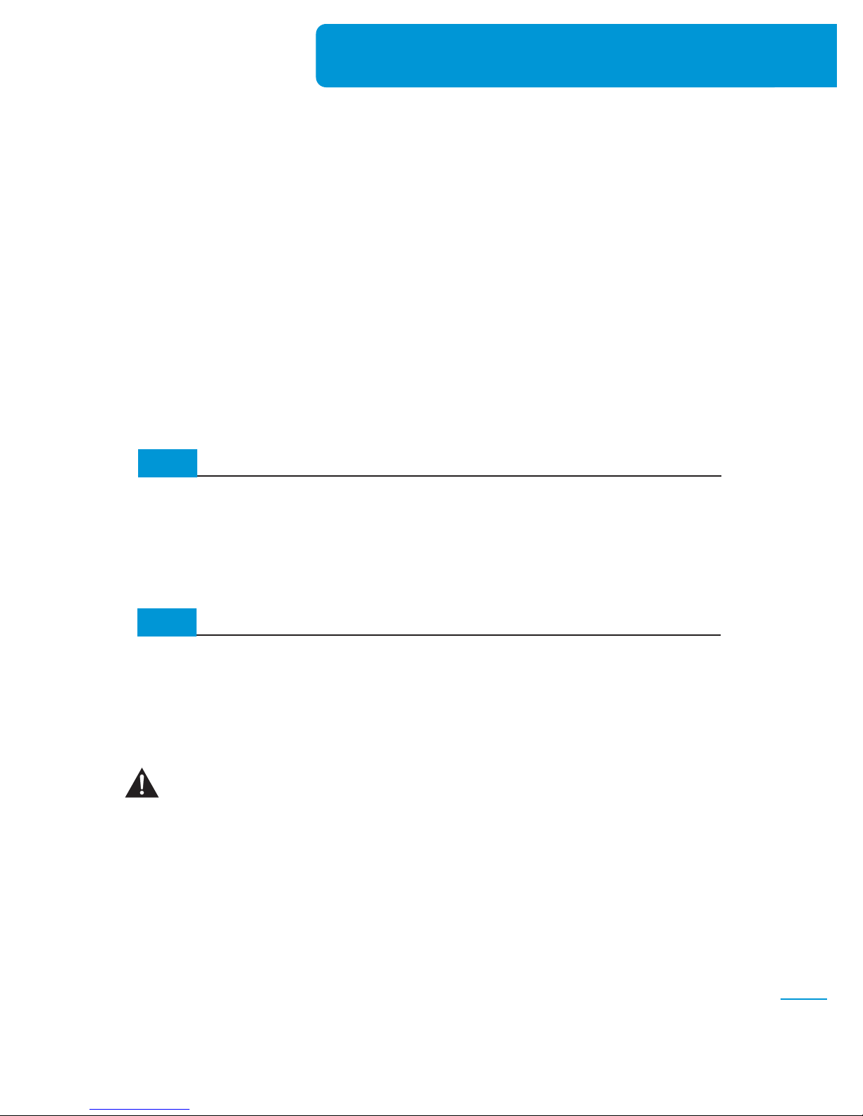
3. Use a web browser to open the VoIP Speaker Configuration Login Page
(Figure 1-1)
. Enter
the following into the browser’s address bar: http://10.16.2.1:8080.
4. Enter the Login Page sign-in credentials:
Username: maint Password: bogen
After entering the Username and Password, click
Submit. The VoIP Speaker Configuration window
(Java-applet) will open
(Figure 1-2)
.
5. Change the DHCP option from “On” to “Off” to
configure static IP Addresses.
NOTE: If after selecting “Off”, a popup screen
appears that says: “Cannot edit Speaker IP when
Primary IP is present. Please un-configure Primary IP from
Utility.” This alerts you to the fact that the speaker is
already configured and must first be un-configured
before you can proceed. See Section 3, How to
Un-configure a VoIP Speaker, for details on how to
un-configure the speaker.
If the VoIP Speaker Configuration Login Page above does not display, wait one minute, try again.
(Fig.1-1)
(Fig.1-2)
✍
✍
After the VoIP Speaker has been plugged into the PoE switch, it will take about a minute for the
VoIP Speaker to boot. Each VoIP Speaker will then repeatedly attempt to get an IP Address from
a DHCP server for one minute. After trying for one minute, the speaker will configure itself with a
default IP Address (10.16.2.1) and default Gateway IP Address (10.16.2.2).
NOTE: Only one speaker can be configured at a time using this IP address assignment process.
Connecting two or more un-configured IP speakers to the network without a DHCP server will cause
duplicate IP addresses and conflicts.
Page 7
✍
8-5
Getting Started
NOTE: If the DHCP “On” option is selected, you will not be able to edit the fields to configure
static address information.
6. Enter values for Speaker IP, Subnet Mask, and Default Gateway, then click Save.The speaker
will automatically reboot and reconfigure the network interface.
NOTE: The VoIP Speaker will accept configuration commands for up to 15 minutes, after which
time it will reboot. It is important that you finish this step within 15 minutes. See Section 6.2.2,
Default IP Address Assignment, for further information on the 15 minute configuration time window.
✍
1.2
Configure Primary Quantum IP Address
After the VoIP Speakers’ IP Address have been configured (using static or DHCP), the next step
is to configure the VoIP Speaker with the Primary Quantum IP Address (the Quantum Node that
is currently set as Primary Node type in the network). All VoIP Speakers should use the same
Primary Quantum IP Address, even if the VoIP Speaker will be added to the Station List of
a different Quantum Node that is not the Primary Node in the network. One or more VoIP
Speakers can be configured at the same time.
1. You need to load the application called VoIP Speaker Locator onto the PC. Copy the file
named
VoIPSpeakerLocator.jar
to the Windows PC that will configure the VoIP Speaker(s).
2. Start the VoIP Speaker Locator application by double-clicking the VoIPSpeakerLocator.jar
icon on the desktop. After displaying a splash screen, the application will display the Device
Discovery Configuration Screen
(Figure 1-3)
.
3. Enter the Windows PC’s IP Address into the Utility IP Address field. This should be the IP
Address for the PC interface that is used to connect to the same network that the VoIP Speakers
are connected to (e.g., 10.10.10.10).
(Fig.1-3)
Page 8
4. Enter a valid Utility Port Number between 4000 and 15000. This Port Number will be opened
on your PC for receiving discovery responses from VoIP Speakers. This document will use
Port 7000.
NOTE: If the VoIP Speaker Locator application is unable to discover any VoIP Speakers, ensure that
the specified Port Number is not being blocked by firewalls on your PC or network hardware.
5. Select Discover All from the Discover Option drop-down menu.
NOTE: If the “Discover Not Configured” option is selected, you will only be able to discover
VoIP Speakers that have not yet been configured. This is useful when there are some VoIP Speakers
in the network that have not yet been configured. This way, the application will only discover
the VoIP speakers that have not yet been configured. If not selected, the application will discover
all the speakers in the network (whether configured or not), requiring you to manually find and
mark the un-configured speakers from the list of discovered speakers (Figure 1-4).
6. Click the Discover button. The Discover button will be highlighted while the application is
discovering VoIP Speakers. If this is the first time you have pressed Discover since starting
the application, a dialog window will open when discovery is completed. The dialog box
will remind you that the Port Number cannot be changed while running the application.
If you need to change the Port Number, restart the application.
NOTE: If you receive the error “Invalid IP Address”, try entering a new/different IP Address.
NOTE: If you receive the error “Port values cannot be edited further,” you cannot change the
port number as it has already been configured.
NOTE: If you need to change the IP Address, utility port or discover option, you must restart the
application.
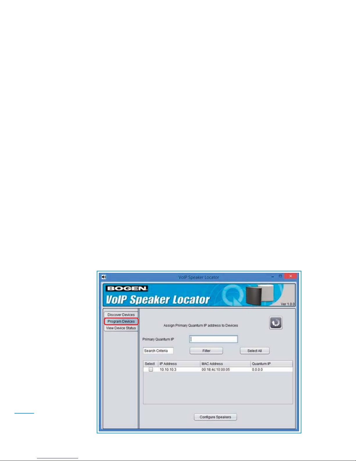
7. When the Discover button is no longer highlighted, click the Program Devices tab on the left
panel
(Figure 1-4)
to proceed to the Assign Primary Quantum IP Address to Devices screen.
A list of VoIP Speakers that have not yet been configured with a Primary Quantum IP Address
will be displayed.
✍
✍
✍
✍
✍
8-6
Getting Started
(Fig.1-4)
Page 9
8-7
Getting Started
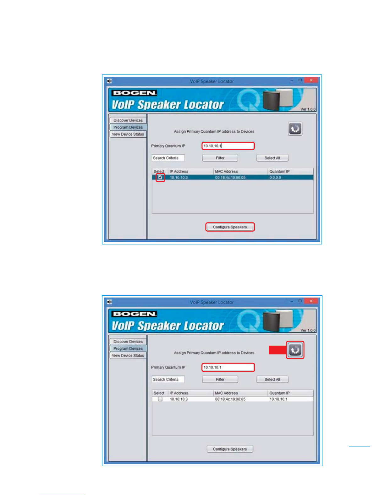
8. Select the VoIP Speaker(s) that you wish to configure (e.g., 10.10.10.3) by clicking on the
checkbox to the left of each speaker listed. A checkmark will appear next to each speaker
selected
(Figure 1-5)
.
9. Enter the Primary Quantum IP Address in the Primary Quantum IP field (e.g., 10.10.10.1).
10. Click Configure Speakers. The selected speaker(s) will be configured.
11. Click the Refresh icon located to the top right of the screen a couple of times until you see
the Quantum IP Address change for all recently configured speakers. (For example, in
Figure 1-6, the speaker’s Quantum IP Address has changed from 0.0.0.0 to 10.10.10.1).
(Fig.1-5)
(Fig.1-6)
REFRESH
BUTTON
Page 10

8-8
Getting Started
(Fig.1-7)
12. Click the View Device Status tab on the left panel
(Figure 1-7).
The VoIP Speaker List screen
will appear. All the VoIP Speakers available in the network will be listed. If a VoIP Speaker
is already configured on a Quantum Node, the Architecture Number assigned to it will
be shown.
Page 11

(Fig.2-1)
(Fig.2-2)
8-9
Adding VoIP Speakers to Quantum List via Quantum Commander
Adding VoIP Speakers to Quantum
List via Quantum Commander
2
The last step to configure a new VoIP Speaker is to add it to the Station
List of a Quantum Node in the network.
NOTE: You will need Quantum Commander Version 1.3.0 or newer.
1. Select a Quantum Node that has an available station slot, preferably a slot that you would not normally use for a physical device.
2. Double-click the station row to bring up the Station Configuration
screen
(e.g., Figure 2-1, Station #26
).
3. From the Station Type drop-down menu, select a Station Type that
matches the VoIP Speaker type you are adding: VoIP Speaker
Only, VoIP Speaker with Call Switch, or VoIP Speaker with NonDial Handset.
4. Enter the Architecture Number (Arch#) for
the VoIP Speaker.
5.
Select the VoIP Speaker’s MAC Address
from the MAC Address drop-down menu
(Figure 2-2)
.
✍
✍
NOTE: If the MAC Address is not displayed, refresh the Station List and try again. If the MAC
Address is still not displayed, reboot the speaker (see Section 4.0, How to Reboot a VoIP Speaker),
wait a couple of minutes, then try again. If the MAC address is still not displayed, there may be an
issue with the VoIP Speaker’s IP Address configuration.
6. Select the desired Volume for the IP Speaker from the Volume drop-down menu (e.g.,
1/4W, 1/2W, 1W, 2W, 4W).
Page 12

8-10
Adding VoIP Speakers to Quantum List via Quantum Commander
7. Enter other required field information (e.g., Zones, Day/Night Admin, etc.) depending on station type.
8. Click Apply
(Figure 2-1).
9. Select Save from the File menu to save the configuration for the VoIP Speaker.
10. After saving, the VoIP Speaker will automatically reboot. Wait a couple of minutes for the VoIP Speaker to
finish rebooting.
11. Check the VoIP Speaker Locator
(Figure 1-7)
. The VoIP Speaker should now have an assigned Architecture
Number. Press Discover, then review the View Device Status tab.
NOTE: If you want to later change the volume of a VoIP Speaker that is currently playing Audio Distribution, the
speaker’s volume will not change until after the speaker: 1) receives an intercom call, 2) is reset, 3) receives a
page, or 4) program distribution is restarted.
NOTE: When VoIP Speakers are provisioned, the VoIP Speaker Primary Quantum IP Address setting must always
be set to the Primary Quantum Node’s IP Address. After that, the VoIP Speaker can be added to any Quantum
Node in the network, regardless of node type (e.g., Primary, Secondary or Normal).
✍
✍
Page 13

8-11
How To Un-Configure a VoIP Speaker
How To Un-Configure
a VoIP Speaker
3
To un-configure a VoIP speaker, follow these steps:
1. Un-configure a VoIP speaker from Quantum Commander by
changing its station type to “n/c”.
2. Discover VoIP Speakers using the VoIP Speaker Locator applica-
tion. See
Section 1.1, Configure IP Address Information
.
3. Un-configure Primary Quantum IP address from the VoIP Speaker
by setting its Primary Quantum IP address to 0.0.0.0
4. Now the VoIP Speaker can be reconfigured using a DHCP or static
IP Address.
✍
Page 14

8-12
How To Reboot a VoIP Speaker
After entering the Username and Password, click Submit.
The VoIP Speaker Configuration window (Java-applet)
will open
(Figure 4-2
).
3. Click Reboot. The VoIP Speaker will reboot.
(Fig.4-2)
How To Reboot a VoIP Speaker
4
You can remotely reboot a VoIP Speaker using the VoIP Speaker
Configuration application:
1. Use a web browser to open the VoIP Speaker Configuration Login
Page
(Figure 4-1)
by entering the following into the browser’s
address bar: http://x.x.x.x:8080
NOTE: Replace
x.x.x.x
with the IP Address of the VoIP Speaker that
you wish to Reboot.
✍
4. Enter the Login Page sign-in credentials:
Username: maint Password: bogen
(Fig.4-1)
Page 15

8-13
Software Updates
Software Updates
5
The VoIP Speaker software can be updated by using Quantum
Commander or VoIP Speaker Configuration.
NOTE: To update all VoIP Speakers, use Quantum Commander.
✍
5.1
Software Update using Quantum Commander
Use the following steps to update the VoIP
Speaker software in all speakers, using
Quantum Commander:
1. Log in to Quantum Commander.
2. On the toolbar, select:
Tools/>Download/>Software All Speakers to update all VoIP Speakers
(Figure 5-1).
3. The Confirm – Download Software dialog
box
(Figure 5-2)
will be displayed. Then Click
“Yes” to continue.
(Fig. 5-1)
(Fig. 5-2)
4. The Software Download dialog box
(Figure
5-3)
will be displayed. Click on Browse to
locate the folder that contains the VoIP
Speaker software.
(Fig. 5-3)
5. Select the file named: ipspkr_x.x.x.tar.gz,
then click Download
(Figure 5-4)
to initiate
the software download to all VoIP Speakers.
NOTE: The
x.x.x
is replaced in the actual file
name with the VoIP Speaker version number.
(Fig. 5-4)
✍
A. UPDATE VIA WEB-BROWSER
Page 16

8-14
Software Updates
6. The Software Download dialog box will display
a list of VoIP Speakers to be updated. Click Start
Download
(Figure 5-5)
to start the download.
7. The Software Download screen
(Figure 5-6)
will display status bars in the Status column
while downloading to each speaker:
8. After the Status has been updated (Completed) for all speakers, click Close
(Figure 5-7)
.
NOTE: If any VoIP Speakers were unavailable for download, a list of those speakers will be
displayed.
9. After the software download is complete, reboot all VoIP Speakers that received the download, either by power cycling the speakers, or by using the VoIP Speaker Configuration tool
on each speaker to initiate a reboot. The VoIP Speakers will install the new software during
reboot. (See
Section 4.0, How to Reboot a VoIP Speaker.
)
NOTE: To upload new software to the VoIP Speakers attached to a single selected Quantum
Node, refer to step 2, select Tools/> Download/> Software /> IP Speakers, then follow these
steps (Figure 5-8).
(Fig. 5-5)
(Fig. 5-7)
(Fig. 5-6)
(Fig. 5-8)
✍
✍
Page 17

✍
5.1
Software Update using Quantum Commander
B. UPDATE VIA SOFTWARE DOWNLOAD
The new standalone Java application version of Quantum Commander includes an enhanced
software update feature. Software Update can now be used to download new software to devices
and automatically reboot devices after they have received updated software. The Software
Update feature tracks device states through the process of receiving software, rebooting, and
reboot completion.
NOTE: Refer to Sections 7.1 and 7.2 to Install and Login to the standalone Java application.
To update software for all VoIP Speakers in your network, follow these instructions:
1. Log into the Quantum Commander using
the standalone Quantum Commander Java
application
(Figure 5-9)
. Click Submit.
(Fig. 5-9)
2. In the Quantum Commander application,
from the “Tools-> Download” Menu, select
“Software –All Speakers”
(Figure 5-10)
.
(Fig. 5-10)
4. A confirmation dialog box will be
displayed
(Figure 5-12)
. Click Yes
to proceed with the software update.
(Fig. 5-12)
3. The Software Download dialog box will then
prompt you for a valid filename for the VoIP
Speaker software
(Figure 5-11)
.
Valid format for speaker software filename
is ipspkr_x.x.x.tar.gz where the x.x.x is
replaced with the version number.
(e.g., ipspkr_1.0.0.tar.gz). Click Download.
(Fig. 5-11)
8-15
Software Updates
Page 18

5. The Software Download window will be
displayed
(Figure 5-13)
.
Click Start Download.
(Fig. 5-13)
9. After all VoIP Speakers have successfully rebooted, the Status column will
then show “Completed”
(Figure 5-17)
.
Click Close.
The Software Download Success window
(Figure 5-18
) will then be displayed.
(Fig. 5-17)
8. If Yes is selected, the Status column will
indicate that the speakers are being
rebooted. The title bar will change to
provide updated status for reboots to
each VoIP speaker
(Figure 5-16)
.
(Fig. 5-16)
6. The Status column will provide download
status. Wait for status column(s) to read
“Completed”
(Figure 5-14)
. Click Close.
(Fig. 5-14)
7. When the “Reboot VoIP Speaker now?”
prompt is displayed
(Figure 5-15)
, click
Yes to reboot all VoIP Speakers, or click
No to skip the reboot.
(Fig. 5-15)
(Fig. 5-18)
8-16
Software Updates
Page 19

5.2
Software Update Using VoIP Speaker Configuration Tool
Use the following to update the VoIP Speaker software using the VoIP Speaker Configuration tool:
1. Use a web browser to open the VoIP Speaker Configuration Login Page
(Figure 5-21)
by
entering the following into the browser’s address bar: http://x.x.x.x:8080
8-17
Software Updates
2. Enter the VoIP Speaker Configuration Login Page sign-in credentials:
Username: maint Password: bogen
(Fig.5-21)
10. If reboot failures occur in any of
VoIP Speakers, the Status column will
show “Failed”
(Figure 5-19)
. In this
case the failed speaker(s) will need
to be power cycled
(Figure 5-20
).
(Fig. 5-19)
(Fig. 5-20)
NOTE: The
x.x.x.x
represents the IP Address of the VoIP Speaker you want to update.
✍
Page 20

8-18
Software Update
4. The Software Download screen
(Figure 5-23)
will
then open. Click Browse.
(Fig. 5-23)
5. Locate the folder that contains the VoIP Speaker
software
(Figure 5-24)
. Select the file named:
ipspkr_x.x.x.tar.gz and Click Download to
initiate the software download to the VoIP
Speakers.
(Fig. 5-24)
6. When the download is complete, an Alert box
(Figure 5-25)
will open stating FTP Success.
After the software download has completed, click on Reboot
in the VoIP Speaker Configuration window
(Figure 5-22)
.
The VoIP Speaker will install the new software during reboot.
(Fig. 5-25)
3. After entering the Username and Password,
click Submit. The VoIP Speaker Configuration
window (Java-applet) will open
(Figure 5-22)
.
Click Software Download.
(Fig.5-22)
NOTE: The
x.x.x
represents the VoIP Speaker
version number.
✍
Page 21

8-19
Notes
Notes
6
6.1
Configuration
When VoIP Speakers are provisioned, the VoIP Speaker Primary
Quantum IP Address setting must always be set to the Primary
Quantum Node’s IP Address. After that, the VoIP Speaker can
be added to any Quantum Node in the network, regardless of
node type (e.g. Primary, Secondary or Normal).
6.2
DHCP Operation
6.2.1
Configuring IP Address for VoIP Speakers Using DHCP
The DHCP server must be configured to always provide the same IP Address to the VoIP Speaker.
This is usually accomplished by mapping the device MAC Address to a permanent IP Address.
If the DHCP server is not configured to provide the same IP Address, and if the VoIP Speaker is
assigned a different address than the address it had while configuring it with Quantum
Commander, the VoIP Speaker will not be available to the Quantum system. (To be available,
it must receive the same address from the DHCP server, or be reconfigured).
6.2.2
Default IP Address Assignment
When a newly installed VoIP Speaker starts, it will attempt for one minute to get an IP Address
from a DHCP server. If the speaker does not receive an IP Address from a DHCP server within
one minute, it will temporarily configure its IP Address to the default 10.16.2.1, to allow
configuration of the speaker at this known default IP address. It will operate in this mode for a
maximum of 15 minutes, and then reboot to make another attempt to receive an IP Address
from a DHCP server.
6.2.3
Using a Previously Assigned IP Address
If a fully configured VoIP Speaker that uses DHCP reboots and does not receive an IP Address
from the DHCP server within one minute, it will automatically use the IP Address that was
previously provided via DHCP. The VoIP Speaker will only do this if it has been configured to
use DHCP and is configured with a valid Primary Quantum IP Address and has been assigned
an Architecture Number. This method will ensure that VoIP Speakers configured to use DHCP
will still operate while in the temporary absence of a DHCP server.
Page 22

Appendix
7
With Quantum release 1.3.0, two standalone Java applications are
included. The standalone “Speaker Configuration” Java application can
be used instead of the web-browser based Speaker Configuration Java
applet. The standalone “Quantum Commander” Java application can
be used instead of of the web-browser based Quantum Commander
Java applet.
Standalone Java applications for Quantum
Commander & VoIP Configuration
7.1
Install and Run Java Applications
NOTE: Several web browser vendors (e.g. Google Chrome, Mozilla Firefox) have dropped
support for Java applets. This directly affects the availability of Bogen’s web-browser based
“Speaker Configuration” and “Quantum Commander” Java applets, making them
inaccessible via some web browsers. Bogen is now providing these two applications to our
customers as standalone Java applications (SpeakerConfig.jar and QuantumCommander.jar).
These standalone Java applications can be used instead of web-browser based applications.
8-20
Appendix
1. Ensure that you have Java installed on your Microsoft Windows computer. Java can be downloaded from: https://java.com/
2. Copy SpeakerConfig.jar and QuantumCommander.jar to your desktop (or any other folder
of your choice).
3. To run the Java applications, double-click on the application’s icon located on the desktop.
4. The application chosen, either Speaker Configuration (Figure 7-1) or Quantum Commander
(Figure 7-2) will display a login window.
(Fig. 7-1)
(Fig. 7-2)
5. Enter a valid Username, Password, and IP Address of VoIP Speaker(s) or Quantum Node(s).
Click Submit.
✍
Follow these steps to install and run the new standalone Java applications for Speaker Configuration
and Quantum Commander.
Page 23

(Fig. 7-3)
(Fig. 7-4)
7.2
Login Window Operational Notes
1. If you have a file called VoipSpeakersList.txt in the same folder where the application's jar
file is located, it will load the IP addresses contained in the file for selection in the login window.
The file is just a list of IP addresses, one per line. If the file does not exist, the application will
simply display the normal text field for the IP address to be entered manually.
2. Adding new IP addresses to the VoipSpeakersList.txt file.
You will notice a "+" button under the "IP Address" label. Pressing the "+" button
will open a dialog asking for IP Address input
(Figures 7-1 and 7-2)
.
Speaker Configuration Specific Options
8-21
Appendix
6. After Successful Login, the application’s
(Speaker Configuration, Figure 7-3; Quantum
Commander., Figure 7-4)
main window will be displayed.
3. If you have a speaker that you visit frequently, make it the first one in the list; then you can
press return after entering "password" and it will automatically select the first IP address from
the list and connect.
4. Sample VoipSpeakersList.txt file
(produces IP address list shown in the Speaker Configuration
Login in Figure 7-1
).
10.10.10.5
10.100.1.213
10.100.1.205
(Fig. 7-5)
The new IP address will be appended to the
VoipSpeakersList.txt file. If the file does not exist,
it will be created. That's all the "+" button does,
allow you to add more IP addresses to the list,
without having to directly edit the file.
Page 24

1. If you have a file called QuantumNodesList.txt in the same folder where the application's jar
file is located, it will load the IP addresses contained in the file for selection in the login window.
The file is just a list of IP addresses, one per line. If the file does not exist, the application will
simply display the normal text field for the IP address to be entered manually.
2. Adding new IP addresses to the QuantumNodesList.txt file.
You will notice a "+" button under the "IP Address" label
(Figures 7-1 and 7-2)
.
Pressing the "+" button will open a dialog asking for IP Address input
(Figure 7-6)
.
Quantum Commander Specific Options
Keep trying to connect
3. If you have a Quantum Node that you visit frequently, make it the first one in the list; then you
can press return after entering "password" and it will automatically select the first IP address
from the list and connect.
The “Keep trying to connect” checkbox
(Figures 7-1 and 7-2)
will force the login window to keep
trying to connect to the selected device, to help prevent receiving connection failed errors
(see Figure 7-7 - Connection failed error)
. This is useful if you know the device has been rebooted,
so you don’t want to keep manually trying to
connect. The Quantum Login window will
keep trying for about 2 minutes, the Speaker
Login window will keep trying for about 3
minutes. There is no way to interrupt the login
window while it’s trying to connect, you have
to wait for it to succeed or timeout.
(Fig. 7-6)
The new IP address will be appended to the
QuantumNodesList.txt file. If the file does not
exist, it will be created. That's all the "+" button
does, allow you to add more IP addresses to the
list without having to directly edit the file.
(Fig. 7-7)
8-22
Appendix
Page 25

NOTES
Page 26

NOTES
Page 27

NOTES
Page 28

www.bogen.com
 Loading...