

Page 1
VM2B
VM2W
VM1W
VM1B
VM-S
ERIES
ALL-ENVIRONMENT
OUTDOOR LOUDSPEAKERS
QUICK START INSTALLATION
AND SETUP GUIDE
Page 2
VM-S
ERIES
ALL-ENVIRONMENT OUTDOOR LOUDSPEAKERS
The NEAR® VM1 and VM2 Outdoor Full-Range Loudspeakers have been purposebuilt to be extremely durable in all weather conditions. With a mix of elegance and
function, the VM1 (4.5” 2-way) and the VM2 (5.25” 2-way) utilize many of NEAR’s
signature features and benefits such as Metal Diaphragm Technology (MDT) woofers
for consistent performance in any environment, and titanium-alloy tweeters that deliver
superior sound quality. The VM-Series speaker enclosure is color-through, micaloaded polypropylene with color-matched aluminum grilles. The VM-Series mounting
system minimizes installation effort and reduces “ladder time” for superior installation
efficiency and safety.
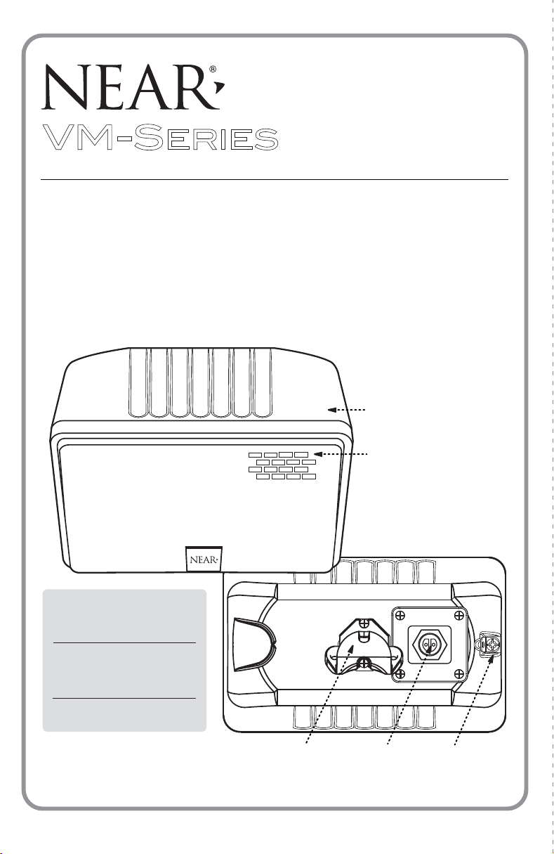
FRONT
VIEW
WEATHER-RESISTANT
ENCLOSURE
HEAVY-GAUGE
ALUMINUM GRILLE
DIMENSIONS
(HORIZONTAL)
VM1B/W
5-1/4” H x 8-1/4” W x 7-3/8” D
(including Bracket)
VM2B/W
6-7/8” H x 9-3/4” W x 8-1/8” D
(including Bracket)
REAR
VIEW
SPEAKER
BRACKET
MOUNT
PLUG-IN
RECEPTACLE
SAFETY CABLE
ATTACHMENT
POINT
Page 3
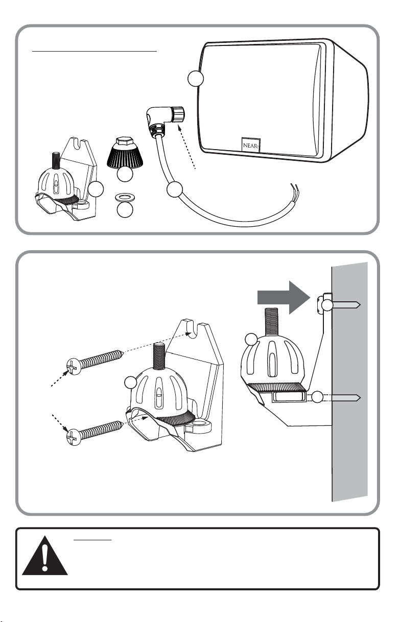
CONTENTS INCLUDE:
1. VM1 or VM2 Loudspeaker
2. Plug-in Connector Cable
3. Clamping Knob
4. Rubber Washer
5. Wall Mount Bracket
1
3
5
PLUG-IN
CONNECTOR
2
(IP68-RATED)
4
Attaching Wall Mount Bracket
to a Wall/Flat Surface
1
WALL MOUNT
BRACKET
A
MOUNTING SCREWS
(USER-SUPPLIED)
Position the Wall Mount Bracket (A) firmly up against a wall or flat
surface and then attach the bracket by inserting 2 mounting screws
(user-supplied) through the 2 mounting holes (B) on the Wall Mount
Bracket. Secure the Bracket flush to surface.
A
SIDE VIEW
B
WALL
B
WARNING: Customer is responsible for selecting the appropriate mounting hardware
and surface. Both the mounting hardware and surface must be capable of withstanding 5x the weight of the suspended assembly. Also, it is recommended that a safety
cable be attached to the unit where specified to preventthe unit from falling should
the mounting hardware or surface attachment fail. Please consult a professional
installer if you are uncertain or have any questions regarding the speaker installation.
Page 4

2
Connecting the Plug-In Connector
Wiring to the VM-Series Speaker
The VM-Series Speakers come factory-ready for a Horizontal Mount. To connect the speaker wiring to
a speaker, simply insert the Plug-In Connector (B) directly into the Plug-In Receptacle (A) located on the
rear of the speaker, just to the right of the Speaker Mount Bracket. NOTE: Both the Plug-In Receptacle
and the Plug-In Connector are “KEYED” items and fit together correctly in only one orientation. Once
the Plug-In Connector has been inserted, rotate the Ring at the end of the connector to fully tighten
(see Plug-In Detail).
When the Plug-In Connector has been properly attached and secured, the speaker cable connection should look as shown (1), ready to be coupled with an amplifier.
PLUG -IN RECEPTACLE
C
VERTICAL
MOUNT
C
PLUG-IN
RECEPTACLE
PLUG-IN
DETAIL
A
ROTATE
RING
B
PLUG-IN
CONNECTOR
SIDE VIEW
HORIZONTAL MOUNT
SPEAKER REAR VIEW
1
A
TO AMP
D
D
SPEAKER MOUNT BRACKET
For a Vertical Mount, the speaker’s
Plug-In Receptacle (C) and Speaker
Mount Bracket (D) must be rotated.
Remove the four screws from the
Plug-In Receptacle and two screws
from the Speaker Mount Bracket,
and rotate each 90-degrees clockwise.
Next, securely re-attach the screws.
Insert the Plug-In Connector (see Plug-In Detail), and the speaker cable
connection should look as shown (2), ready to be coupled with an amplifier.
SPEAKER REAR VIEW
2
TO
AMP
Page 5
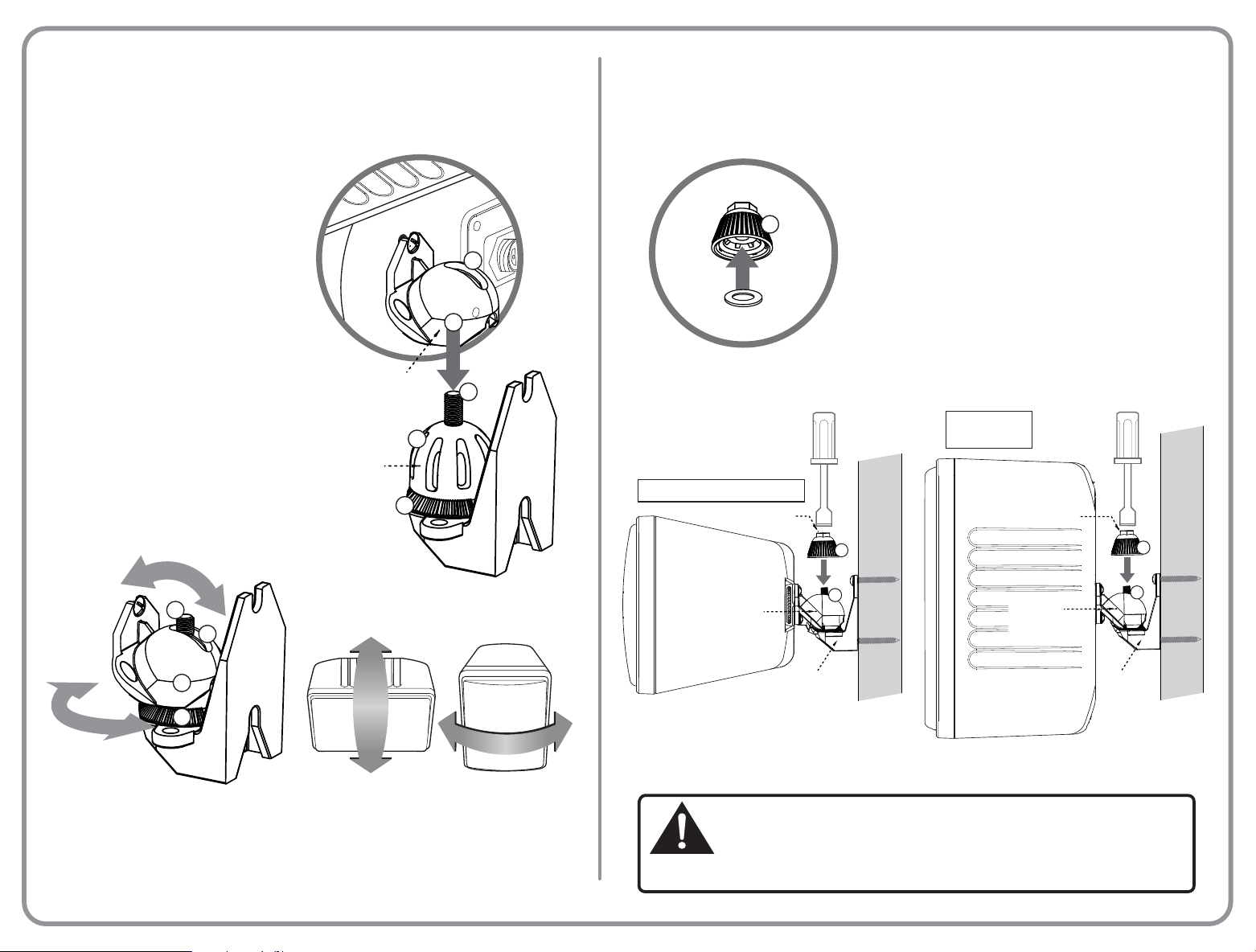
3
A
Situating the VM-Series Speaker
onto the Wall Mount Bracket
MOUNT DETAIL
Mounting the VM-Series Speaker
onto the Wall Mount Bracket
B
3
The Speaker’s Mount Bracket is already
attached to the speaker’s rear and the Wall
Mount Brac
wall/flat surface.
Mount above the Wall
slowly lower the “socket” that is the Speaker
Mount Bracket (A) down on to the “ball” that
is the Wall Mount Bracket (B), allowing the
Threaded Screw (C) on the Wall Mount
Bracket to slide up through the open slot (D)
of the Speaker Mount Bracket. Continue to
lower the Speaker Assembly until it is now
resting upon the Wall Mount Bracket. At this
point the Speaker Assembly is able to hang
from the Wall Bracket, which will now free
up both hands for adjusting the speaker’s
position or additional wiring.
ROTATE
ket has been firmly secured to a
Now position the Speaker
Mount Bracket and
UP/DOWN
TILT
C
D
ON
WALL
A
E
D
A
SPEAKER
MOUNT BRACKET
WALL
MOUNT
BRACKET
MOUNTED HORIZONTALLY OR VERTICALLY,
THE SPEAKER CAN BE ROTATED/ANGLED
BOTH LEFT OR RIGHT, UP AND DOWN
B
E
C
ON
WALL
CLAMPING
KNOB
F
RUBBER
WASHER
HORIZONTAL MOUNT
CLAMPING KNOB
SPEAKER
MOUNT
BRACKET
WALL MOUNT
SIDE VIEW
C
BRACKET
To finalize the mounting procedure, first insert the
provided washer up and into the Clamping Knob (F).
With the Speaker Assembly now in its final desired
orientation, secure it into position by bringing the
Clamping Knob (F) down on to the exposed portion of
the Wall Mount Thread (C) and then screw the knob
into place. A 1/2” Socket or Nut Driver can be used
to firmly tighten the Clamping Knob so that the entire
assembly is now secured.
1/2” SOCKET
OR NUT DRIVER
F
WALL
VERTICAL
MOUNT
1/2” SOCKET OR
NUT DRIVER
CLAMPING KNOB
SPEAKER
MOUNT
BRACKET
C
WALL MOUNT
BRACKET
SIDE VIEW
F
WALL
The Speaker can now be positioned in a variety of angles. To focus the speaker
orientation in an upward or a downward manner, tilt the speaker in a back-and-forth
motion within the Speaker Bracket Slot (D) and Mount Bracket Thread (C) axis. The
Speaker can also be rotated on an angle or side-to-side using the “Ball & Socket”
design of the brackets and then locked into position by the Wall Mount Bracket
“teeth” (E) as well as the Clamping Knob (see section 3B).
YOU MUST ACCURATELY FOLLOW THE INSTRUCTIONS FOR ALL THE
PARTS INVOLVED IN THIS INSTALLATION. FAILURE TO DO SO CAN
CAUSE SERIOUS INJURY OR DEATH TO YOURSELF OR OTHERS AND
MAY EXPOSE YOU TO POSSIBLE LEGAL ACTION. PLEASE CONSULT
A PROFESSIONAL INSTALLER IF YOU ARE UNCERTAIN OR HAVE ANY
QUESTIONS REGARDING THE SPEAKER INSTALLATION.
Page 6

Connecting a Safety Cable
to the VM-Series Speaker
4
It is HIGHLY recommended that a safety cable be used
to help further secure the VM-Series speaker. There is
a Safety Cable Attachment Point Screw (A) located on
the rear of the speaker. Slightly loosen this Screw, then
connect a (user-supplied) safety cable by winding the
cable around it.
After fully re-tightening the Safety Screw, the cable now
attached to the speaker can be connected to another
fastening point (ex. ceiling beam) to provide additional
security against disconnection/falling.
HORIZONTAL MOUNT
SAFETY CABLE
(USER-SUPPLIED)
SAFETY CABLE
ATTACHMENT POINT
(SCREW)
A
VERTICAL
MOUNT
A
SPEAKER REAR VIEW
SPEAKER REAR VIEW
Page 7
LIMITED WARRANTY: Exclusion of Certain Damages
The NEAR® VM-Series Loudspeakers are warranted to be free from defects in material and workmanship for 7 (seven) years
from the date of sale to the original purchaser. Any part of any NEAR product covered by this warranty that, with normal
installation and use, becomes defective (as confirmed by Bogen upon inspection) during the applicable warranty period, will be
repaired or replaced by Bogen, at Bogen’s option, provided the product is shipped insured and prepaid to: Bogen Factory Service
Department, 4570 Shelby Air Drive, Suite 11, Memphis, TN 38118 USA. Repaired or replacement product will be returned to you
freight prepaid. This warranty does not extend to any of our products that have been subjected to abuse, misuse, improper
storage, neglect, accident, improper installation or have been modified or repaired or altered in any manner whatsoever, or where
the serial number or date code has been removed or defaced.
THE FOREGOING LIMITED WARRANTY IS BOGEN’S SOLE AND EXCLUSIVE WARRANTY AND THE PURCHASER’S SOLE
AND EXCLUSIVE REMEDY FOR NEAR PRODUCTS. BOGEN MAKES NO OTHER WARRANTIES OF ANY KIND, EITHER
EXPRESS OR IMPLIED, AND ALL IMPLIED WARRANTIES OF MERCHANTABILITY OR FITNESS FOR A PARTICULAR
PURPOSE ARE HEREBY DISCLAIMED AND EXCLUDED TO THE MAXIMUM EXTENT ALLOWABLE BY LAW. Bogen's liability
arising out of the manufacture, sale or supplying of NEAR products or their use or disposition, whether based upon warranty,
contract, tort or otherwise, shall be limited to the price of the product. IN NO EVENT SHALL BOGEN BE LIABLE FOR SPECIAL,
INCIDENTAL OR CONSEQUENTIAL DAMAGES (INCLUDING, BUT NOT LIMITED TO, LOSS OF PROFITS, LOSS OF DATA
OR LOSS OF USE DAMAGES) ARISING OUT OF THE MANUFACTURE, SALE OR SUPPLYING OF NEAR PRODUCTS, EVEN
IF BOGEN HAS BEEN ADVISED OF THE POSSIBILITY OF SUCH DAMAGES OR LOSSES. Some States do not allow the
exclusion or limitation of incidental or consequential damages, so the above limitation or exclusion may not apply to you.
This warranty gives you specific legal rights, and you may also have other rights which vary from State to State.
NEAR products that are out of warranty will also be repaired by the Bogen Factory Service Department -- same address as above
or call 201-934-8500. The parts and labor involved in these repairs are warranted for 90 days when repaired by the Bogen
Factory Service Department. All shipping charges in addition to parts and labor charges will be at the owner's expense. All returns
require a Return Authorization number. For most efficient warranty or repair service, please include a description of the failure.
Products manufactured and labeled by other companies may be covered by warranties offered by such companies. Please call
Bogen Customer Service or refer to product packaging for manufacturer’s warranty for non-NEAR branded products.
11/2014
YOU MUST ACCURATELY FOLLOW THE INSTRUCTIONS FOR ALL THE
PARTS INVOLVED IN THIS INSTALLATION. FAILURE TO DO SO CAN
CAUSE SERIOUS INJURY OR DEATH TO YOURSELF OR OTHERS AND
MAY EXPOSE YOU TO POSSIBLE LEGAL ACTION. PLEASE CONSULT
A PROFESSIONAL INSTALLER IF YOU ARE UNCERTAIN OR HAVE ANY
QUESTIONS REGARDING THE SPEAKER INSTALLATION.
NEAR is a Division of Bogen Communications, Inc.
www.nearspeakers.com
Tel. (855) 350-6327
Specifications are subject to change without notice.
© 2016 Bogen Communications, Inc.
740-00008A
1611
 Loading...