

Page 1
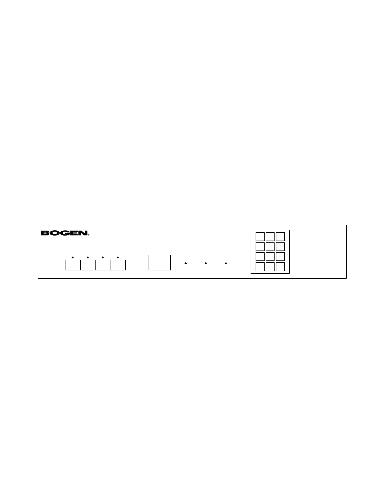
TELEMEDIA CONTROLLER
Model TMC-4
Installation and Operation Instructions
RELEASE
# MANUAL/PROGRAM
1234
STATIONS IN USE
PROGRAM WINDW
LEARN ERROR POWER
1 2 3
4 5 6
7 8 9
0 #
*
MODEL TMC-4 TELEMEDIA CONTROLLER
*
Page 2

Introduction
The Bogen TMC-4 is a programmable universal media-source
controller capable of learning and reproducing the infrared
commands for consumer audio-visual products. It is designed
for operation with various telephone switches (requires use of
Bogen TAM-B access modules), or from the MultiCom 2000
System telephones. When used with the MultiCom 2000 systems, the TMC-4 provides additional features such as: reserving
media source, quick reconnect code, menu driven access, and
current user identification.
Each TMC-4 panel has four media 'stations' and can simultaneously control up to four different media-sources devices from
standard touch tone telephones.
The TMC-4 decodes the DTMF tones from the telephone keypad. The controller then transmits an infrared control signal to
the media-source via a small transmitter, which is mounted
over the media-source infrared receiver. Any function that is
available the media-source's remote control can be learned up
to 30 commands. In addition, the unit permits manual control
directly from the keypad on the TMC-4
Installation
The TMC-4 is designed for rack mounting and requires 3-1/2"
of rack panel space. The equipment to be controlled should be
mounted in the same rack directly above or below the TMC-4.
Power requirements are 120 VAC, 60Hz, 0.1A.
When installing a MultiCom 2000 system, each station on the
TMC-4 is connected directly to the annunciator (A) and
ground (G) terminals of a station on the relay module. See figure 1A below.
When used with other telephone systems, one Bogen Model
TAM-B Telephone Access Module is required for each media
station (Diodes CR27 and CR28 must be removed from the
TAM-B for proper DTMF communications.) Refer to Figure 1B
below. Follow the instructions included with the TAM-B for
proper connection to the telephone system. Connect output
terminals PT and PR on the TAM-B to the A and G terminals of
a station on the TMC-4. Connect the contact closure N.O.and
COM terminals on the on the TAM-B to the respective station's EXTERNAL INPUT and G terminals on the TMC-4.
To connect the TMC-4 to a media source, plug the IR transmitter into the INFRARED SIGNAL OUTPUT. The IR transmitter is then mounted over the infrared detector on the
media source device. Make sure the infrared detector window
is clean and free of any oils before removing the self-adhesive
backing and mounting the transmitter.
Note
The location of the media-source's infrared detector
varies between manufacturers.You can use the remote
control at close range to locate the detector.
1
2
3
4
STATION INPU TS
EXTERNAL INPUTS
1
RAMSEY, NJ
MADE IN USA
MODEL TMC-4
To ground and annunciator
terminals of a station on the
MultiCom 2000 Relay Module
G
A
INFRARED SIGNAL OUTPUTS
1
Infrared transmitter to
device under control.
234567 8GG
2 3 4
PHONE SYSTEM
EXT VOX ENABLE
PAGING OUTPUT
CONTACT CLOSURE A
POWER SUPPLY
(TRUNK ACCESS ONLY)
T
R
+M
-M
PT
PR
N.O.
COM
+24/48
-24/48
TAM -B
1234
STATION INPU TS
EXTERNAL INPUTS
1
RAMSEY, NJ
MADE IN USA
MODEL TMC-4
INFRARED SIGNAL OUTPUTS
1
Infrared transmitter to
device under control.
2345678GG
2 3 4
Figure 1A - Connection of TMC-4 to MultiCom 2000 System (1 Station Shown)
Figure 1B - Connection of TMC-4 to Telephone System using TAM-B (1 Station Shown)
2
Page 3

Power Up
The TMC-4 is shipped fully tested and will all functions cleared.
When power is first applied, LED's illuminate and/or flash and
the unit runs a self test of nonvolatile memory. If the unit
encounters an error during the self test, the error LED will
flash for one second, Following the self test, the unit enters its
ready mode.
Programming
The TMC-4 operates as four independent controllers in one
package. Each station can learn up to 30 commands from the
media-source's remote control unit. These commands can then
be activated from the telephone keypad or the TMC-4 front
panel keypad. Any infrared command can be assigned to any
telephone key combination, however it is recommended that
you follow the sequence provided in Table 1. This will ensure
compatibility with telephone overlays and future product
enhancements.
Note
The front panel keypad is used during programming
and manual operation. In these instructions, numbers
or symbols appearing in brackets ([0] through [9] and
[#] and [*] refer to the individual keys on the tele-
phone or TMC-4 keypad which must be pressed.
During operation from a telephone keypad, the first 10 commands are activated with a single keypress - [0] through [9] see Table 1. The second ten commands are activated by pressing [#] followed by [0] through [9]. The third ten commands
are activated by pressing [*] followed by [*] or [1] through [9].
See Table 1.
When programming the TMC-4, or when using the front panel
keypad for manual operation, the command numbers correspond to the telephone keypad numbers as shown in Table 1.
Determine Programming Distance
Before programming, determine the optimum distance that the
media-source's remote control unit must be from the TMC-4
controller.
1. Press and hold down the MANUAL/PROGRAM key ([#]) for
at least 5 seconds. All STATIONS IN USE LEDs will begin flashing. After 5 seconds, all LED's will light solid (station select
mode).
2. Enter a station number: [1] [2] [3] or [4]. All other station
LEDs will go out.
A. Aim the media-source's remote control at the TMC-4
PROGRAM WINDOW (the remote control should point
directly at the center of the PROGRAM WINDOW).
B. Press and hold any of the remote's function buttons.
The LEARN LED will flicker.
C. Slowly pull the remote control straight back from the
PROGRAM WINDOW while holding the button
down. Note the distance at which the LEARN LED
stops flickering. Use 1/3 of this distance when programming commands.
Note
The range of the remote has to be determined only once
for each brand or remote control used. but is critical for
proper command learning. Remote control units vary
widely in signal output - too close to the TMC-4 may over-
load the receiver, too far will not provide proper signal
3.To return the station select mode. Press [#]. To return to
the ready mode, press [#] [#].
Program Commands
1. Press and hold down the MANUAL/PROGRMA key ([#])
for at least 5 seconds. All STATIONS IN USE LEDs will begin
flashing. After 5 seconds, all LED's will light solid (station
select mode).
Table 1
Controller Telephone Function
Keypad Keypad Command
[0] [0] [0] Power
[0] [1] [1] Play
[0] [2] [2] Pause
[0] [3] [3] Stop
[0] [4] [4] Rewind
[0] [5] [5] Fast Forward
[0] [6] [6] Channel Up
[0] [7] [7] TV/VCR
[0] [8] [8] Display
[0] [9] [9] Channel Down
[1] [0] [#] [0] Power Off
[1] [1] [#] [1] User Definable
[1] [2] [#] [2] User Definable
[1] [3] [#] [3] User Definable
[1] [4] [#] [4] Step Back
[1] [5] [#] [5] Step Forward
[1] [6] [#] [6] User Definable
[1] [7] [#] [7] User Definable
[1] [8] [#] [8] User Definable
[1] [9] [#] [9] User Definable
[2] [0] [*] [*] User Definable
[2] [1] [*] [1] User Definable
[2] [2] [*] [2] User Definable
[2] [3] [*] [3] User Definable
[2] [4] [*] [4] User Definable
[2] [5] [*] [5] User Definable
[2] [6] [*] [6] User Definable
[2] [7] [*] [7] User Definable
[2] [8] [*] [8] User Definable
[2] [9] [*] [9] User Definable
3
Page 4

C. Return to the station select mode by pressing [#].
Return to the ready mode by pressing [#] [#].
Operation
Manual Operation
The TMC-4 can be operated directly from its front panel. This
feature is useful for verifying commands or controlling equipment that is easier to access remotely. To send remote commands from the TMC-4 keypad:
1. Briefly Press [#].All STATIONS IN USE LEDs will flash.
2. Enter the desired station number: [1] [2] [3] or [4].All
other station LEDs will go out.
3. Select a command ([0] [0] to [2] [9], see Table 1). If a command has been stored, the controller will issue that command.
If not command has been stored for the selected number, the
ERROR LED will flash for one second.
4.At this point you can:
A. Repeat Step 3.
B. Press [#] to return to Step 2.
C. Press [#] [#] to return to the ready mode.
Remote Interface (MultiCom 2000)
Remote access can be through a MultiCom 2000 system telephone. A valid station connect code is sent by the MultiCom
system when a user calls a media station extension number. (A
media station is one programmed as a Level 12 station during
MultiCom 2000 system programming.) If the station has not
been reserved the calling party will be connected. If the media
station had been already reserved for them, the reconnect
code [9] [9] may be used to achieve media control.
After a MultiCom 2000 connect code is received:
1.The unit connects to respective station and the station's inuse LED illuminates. A ready beep is sent every 2 seconds to
the calling station. The station is reserved until released by the
MultiCom 2000, the user, or the TMC-4.
2. The TMC-4 waits for DTMF tones. If a keypad number [0]
through [9],[#] [0] through [#] [9], or [*] [*], or [*] [1] through
[*] [9] are pressed, the controller will try to send the corresponding command. If successful, a valid tone will be heard, if
unsuccessful, a error tone will be heard.
3. If the key sequence [*] [0] is received, or if the MultiCom
2000 sends a disconnect code, the TMC-4 will disconnect the
station and shut off the station's in use light.
2. Enter a station number [1] [2] [3] or [4]. All other station
LEDs will go out.
3.To teach the TMC-4 a command, enter a command number
on the TMC-4 keypad ([0] [0] to [2] [9], see Table 1). At this
point the LEARN LED will begin flashing.
4.Aim the remote control at the PROGRAM WINDOW. Press
and hold down the button on the remote for the function to
be assigned to that command number. Once the function is
successfully learned, the LEARN LED will go out and the code
will be stored in memory. If there was a learn error, the
ERROR LED will flash briefly and the LEARN LED will light
again. At this point you can repeat this step.
5.You can now:
A. Repeat steps 3 & 4 and enter a new number to program
another command.
B. Overwrite the command by repeating Steps 3 & 4,
entering the same number.
C. Return to the station select mode by pressing [#].
Return to the ready mode by pressing [#] [#].
Canceling Commands
Commands can be overwritten with new commands using the
procedure above. To cancel a command without overwriting,
use the procedure below. (During operation, a "no command"
error tone will be sent to the telephone if no command has
been programmed for a specific sequence.)
1. Press and hold down the MANUAL/PROGRAM key ([#])
for at least 5 seconds. All STATIONS IN USE LEDs will begin
flashing. After 5 seconds, all LEDs will light solid (station
select mode).
2. Select the desired station number: [1] [2] [3] or [4].All
other station LEDs will begin flashing.
3. Press [*].The station LED will begin flashing.
4. Enter the number of the command to be cancelled by
pressing [0] [0] to [2] [9] on the TMC-4 keypad. The command is instantly cancelled
5.At this point, you can:
A. Press [*] and a different command number to cancel
another command
B. Enter a command number without previously pressing
[*].This will illuminate the LEARN LED and permit you
to program a new function for the command number
(same as overwriting in above procedure).
4
Page 5

Remote Interface (TAM-B)
The TMC-4 can be accessed remotely by an external contact
closure between a station external input and ground. The TAMB provides this closure after being accessed as an extension of
the telephone system. When the external inputs are activated:
1.The unit connects the respective station, the station's in-use
LED illuminates. A ready beep is sent every 2 seconds to the
calling station. The station is reserved until released by the
TAM-B, the user, or the TMC-4.
2.The TMC-4 waits for DTMF tones or a disconnect code. If
key pad numbers [0] through [9], [#] [0] through [#] [9], or [*]
[*], or [*] [1] through [*] [9] are pressed, the controller will try
to send the corresponding command. If successful, a valid tone
will be heard, if unsuccessful, an error tone will be heard.
3.After a preset time, if the user does not hang up or send the
disconnect code ([*] [0]), the TAM-B will automatically hang up.
Releasing a station directly from the TMC-4
If at any time it becomes necessary to free the device currently being controlled, it can be released directly from the
TMC-4
To release a station:
1. Press [*]. The in-use LEDs of all stations currently in use will
flash.
2. Enter the number of station to be released. That station will
be released and the stations light will go out.
Service
There are not user-serviceable parts within the unit. The warranty may become void if repairs are by other than Bogen
Factory Service Department. For information on warranty
repair, contact the Factory.
Technical service is available for the Bogen Applications
Engineering Department.
Bogen Communications, Inc.
50 Spring Street, Ramsey, NJ 07446
U.S.A.
Phone (201) 934-8500
Fax (201) 934-9832
Specifications
Interface
LEDs
4 Yellow STATIONS IN USE
1 Red ERROR
1 Green LEARN
1 Green POWER
Telephone style keypad
STATION INPUTS terminal block
EXTERNAL INPUTS terminal block
INFRARED SIGNAL OUTPUTS RCA jack
Digital Section
CPU - Intel 80C32 12MHz
Memory - 1 each 27C256 EPROM
3 each 28C64 EEPROM's
Infrared Section
Detectable IR transmission schemes:
1. Envelope Modulation
2. Pulse Modulation
Carrier Modulation Range: 25-92 kHz
Pulse Modulation Width: 15x10-6 sec.
Power Requirements
120 VAC, 60 Hz, 0.1A
5
Page 6

Copyright 2002 Bogen Communications, Inc.
Part No. 54-5929-02r1
Printed in U.S.A. 0802
 Loading...