

Page 1

A DIVISION OF LEAR SIEGLER, INC.
UBLIC
The
Bogen
mixer-equalizer-amplifiers, designed for professional-quality
sound systems that once required custom audio equipment. The
CT60B,
rated at 60 watts, and the
output, are comprised of integrated circuits, silicon transistors and
diodes with the latest state-of-the-art active 2/ 3 octave equalization
circuitry.
Four low-impedance, transformer isolated, balanced microphone inputs, (expandable to six with an accessory PMM-2B)
each with individual volume controls, are convertible to highimpedance inputs by rearranging jumpers on the printed circuit
board. A phantom supply for the use of condenser microphones is
built into these units. Professional three-pin female, XLR-type
microphone connectors are provided on the rear panel.
Two auxiliary channels, with an
can be used for inputs from a tuner, tape/cassette player,
phonograph with a ceramic cartridge, or an optional
Multiple Tone Generator.
Built-in microphone precedence, remote volume control,
500/600-ohm line input and output, with accessories, tape and
tape/ booster outputs, amplifier bridging, and connecting amplifiers’ outputs in series are among the many capabilities of these
units.
Ten slide controls, with detented flat positions, allow the
selected frequency equalizer filter circuit to meet individual
installation requirements. Feedback is virtually eliminated, while
intelligibility is greatly improved, and usable power is increased.
A recessed screwdriver-adjustable front panel control for an
electronic compressor circuit is also provided. This circuit
compensates for poor microphone technique or a variety of
announcers, and it eliminates “blasting” in background music
applications.
Screw terminals on the rear panel allow connections to standard
speaker impedance taps, as well as connections for
70-volt balanced lines.
The amplifier operates from a
three-prong line cord provides automatic grounding when
connected to a three-wire grounded power outlet. The power line is
protected by a circuit breaker, and the output transistors by a
thermal overload device, which shuts off the unit when the
temperature of the heat sink rises excessively.
ADDRESS
Models
CT60B
and
CT1OOB
105-125
are versatile
CT100B,
AUXl/
rated at 100 watts
AUX2 fader control
volt, 60 Hz source. A
preamp-
25-volt
TG-4B
and
INSTALLATION
UNPACKING
The amplifier was carefully checked before leaving the factory.
Inspect shipping container and unit carefully for indications of
improper handling. If the unit has been damaged, make an
immediate claim to the distributor from whom it was purchased. If
the amplifier was shipped to you, notify the carrier without delay
and place your claim.
MODELS
CT60B
and CTIOOB
POWER AND GROUNDING
The ac line cord has a three-prong plug which should be plugged
into a three-wire grounded, 120 volt, 60 Hz outlet. As it is
important to ground the amplifier, where a three-wire outlet is not
available, use an adapter (e.g., Leviton No. 5017) and connect the
grounding pigtail to the screw securing the wall plate. If the wall
plate screw is not grounded, connect a wire from the GND
terminal of the amplifier to a suitable ground.
AUXILIARY POWER
CAUTION
Use the ON/OFF switch on a phonograph or
other accessory unit connected to the auxiliary
receptacle, as the power switch on the amplifer
does not control this receptacle.
The auxiliary power receptacle on the rear chassis is a three-wire
grounded outlet which can supply power to accessory equipment
in the sound system. Be sure that the accessory component does
not require more than 300 watts. The power switch does not
control this receptacle.
Associated equipment connected to the auxiliary receptacle
with a three-prong line cord will be grounded, providing the
amplifier line cord has been properly grounded.
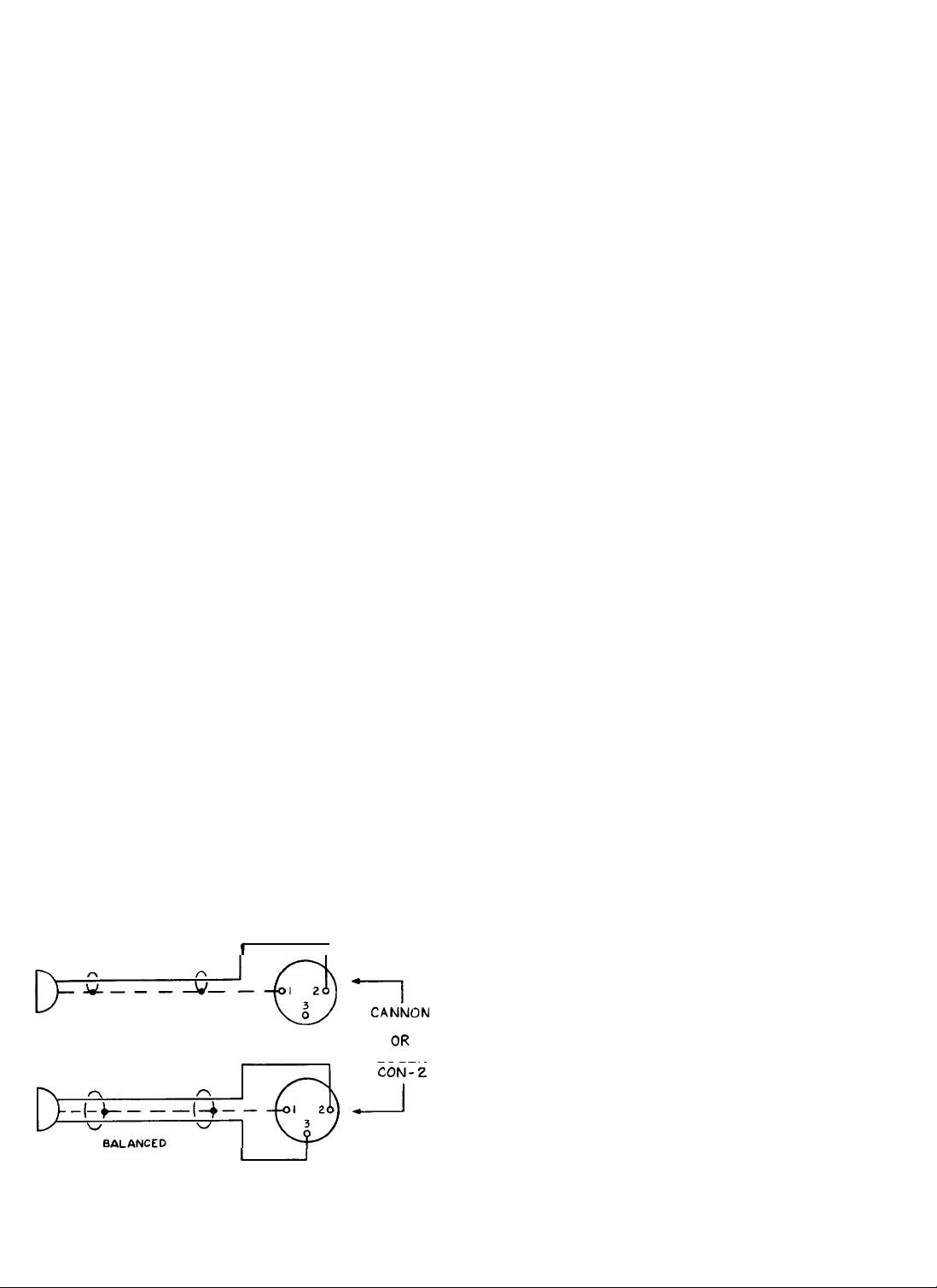
INPUT CONNECTIONS
LOW-IMPEDANCE BALANCED MICROPHONES:
amplifier is designed for direct connection of low-impedance
balanced microphones to the MIC input receptacles of the
amplifier. The microphone lead should be a two-conductor
shielded cable terminated in a Cannon XLR312-C or
CON-2 connector, as shown in Figure 1.
CONDENSER MICROPHONES:
as for low-impedance balanced microphones.
HIGH-IMPEDANCE MICROPHONES: The
should be a singleconductor shielded cable under 35 feet in length
and terminated in a Cannon XLR312-C or
connector, as shown in Figure 1. For information regarding the
use of high-impedance microphones, see notes on the schematic
diagram.
MICROPHONE PRECEDENCE: A built-in circuit provides
microphone precedence for special announcements. A customersupplied SPST switch with normally-open contacts is required for
this function. When the contacts are closed, the auxiliary and other
microphone inputs are muted. (See
diagram and related notes.)
Connect in the same manner
microphone lead
Bogen
TSlOl
in the schematic
The
Bogen
CON-2
Printed in USA 8305
54-5751-01
Page 2
Power Output:
RMS
@
1000 Hz
Frequency Response:
Regulation
Line Fusing
full
Sensitivity (for
&
Noise
Hum
(below rated output)
Inputs (impedance)
Outputs (impedance)
Input/Output
Connectors
Controls
Equalizer Filters
Compression
Semi-conductors
Power Source/
Consumption
Dimensions
Shipping Weight
output)
TECHNICAL SPECIFICATIONS
CT100B
100
w @ less than 2%
total harmonic distortion
±2
50 Hz to 15 kHz
2dB
Resettable Circuit Breaker 2.5A
LO-Z balanced MIC, 0.3
LO-Z balanced MIC -55
4 LO-Z balanced dynamic or condenser MIC inputs, each convertible to HI-Z MICs; 2 HI-Z
with optional WMT-1 accessory; remote volume control for all MIC
4,6-8, 16 ohm speaker taps,
25 VCT and 70V balanced 25 VCT and 70V balanced
or unbalanced lines. or unbalanced lines.
Tape and Tape/ Booster, 500/600-ohm line output with WMT-1 optional accessory.
MIC, professional 3-pin audio connectors (female) Cannon XLR313 or Switchcraft C3F
Series; HI-Z standard phono jacks for Tape, Tape/ Booster, Bridging, and optional accessory
WMT-1 output; provision for optional WMT-I input; screw terminals for speaker connections.
10 filters centered at preferred
21 silicon transistors, 10
120
V, 50/60
23 lbs., 12 oz. (10.8 kg.)
AUX inputs with fader control;
4 MIC Volume, AUX
10 Equalizer Filter Slide Controls, Compressor Control, Power Switch
1250,2000,3150, and 5000 Hz. Boost/Cut:
5 ms. attack time, 2 s. decay time, max. compression 30 dB
IC’s,
10 diodes 19 silicon transistors, 10
Hz, 2.5A, 300W 120 V,
16 3/8”
W x
13¾”
mV;
HI-Z MIC, 3
dB;
HI-Z MIC -60
l/
AUX 2 - fader, MASTER VOLUME,
IS0
center frequencies of 80, 125, 200, 315,
D x
4¾”
H (41.5 x 34.9 x 12 cm)
dB
500/ 6OO-ohm
total harmonic distortion
Resettable Circuit Breaker
mV;
dB;
8,16
CT6OB
60 w
@
less than 2%
AUX.
0.15V
AUX -70
line input
±12
dB
&
AUX. inputs.
ohm speaker taps,
dB
50/60
Hz,
22 lbs. (10 kg.)
500,
IC’s,
1.6A,
1.6A
800,
10 diodes
170W
1/AUX
AUX
are provided for high-level, high impedance inputs. These may be
used to connect a tuner, tape/cassette player, record player
utilizing a ceramic cartridge, or the input from an accessory
WMT-1 line-matching transformer. (Refer to Accessories Section.)
An input signal of 0.15 volts is required to obtain full output from
the amplifier.
B
.74-2883-01
CF-qTJ
HIGH IMPEDANCE MICROPHONE
LOW IMPEDANCE OR CONDENSER
2 INPUTS: Two auxiliary inputs with a fader control
MICROPHONE
Figure 1
1
u
-
Microphone Cable Connections
I
x,,,?,,
XLR-3-12C
BOGEN
Use singleconductor shielded cable terminated in an RCA
phono plug for connecting an auxiliary component. If hum is
experienced after making connections, run a ground
the chassis of the auxiliary unit and the GND terminal of the
amplifier.
BRIDGING: Two CT-B amplifiers can be bridged together to
double the number of inputs and outputs. Connect a singleconductor shielded cable, terminated in an RCA phono plug at
each end, between the rear panel BRIDGING receptacles of the
two amplifiers. This cable should not exceed 20’in length. If more
than two amplifiers are to be bridged use a
BRIDGING GND ONLY terminals on the rear panel terminal
strip
(TS101)
must also be connected to each other. Any input to
either amplifier will then be fed through and available at the output
of both amplifiers. The amplifiers must each feed separate speaker
systems.
When two amplifiers are bridged together, any
adjustment of the MASTER, COMPRESSION
or Acoustic Equalizer controls in one amplifier
will not affect the output of the other amplifier.
2
wire
“Y”
adapter. The
between
Page 3
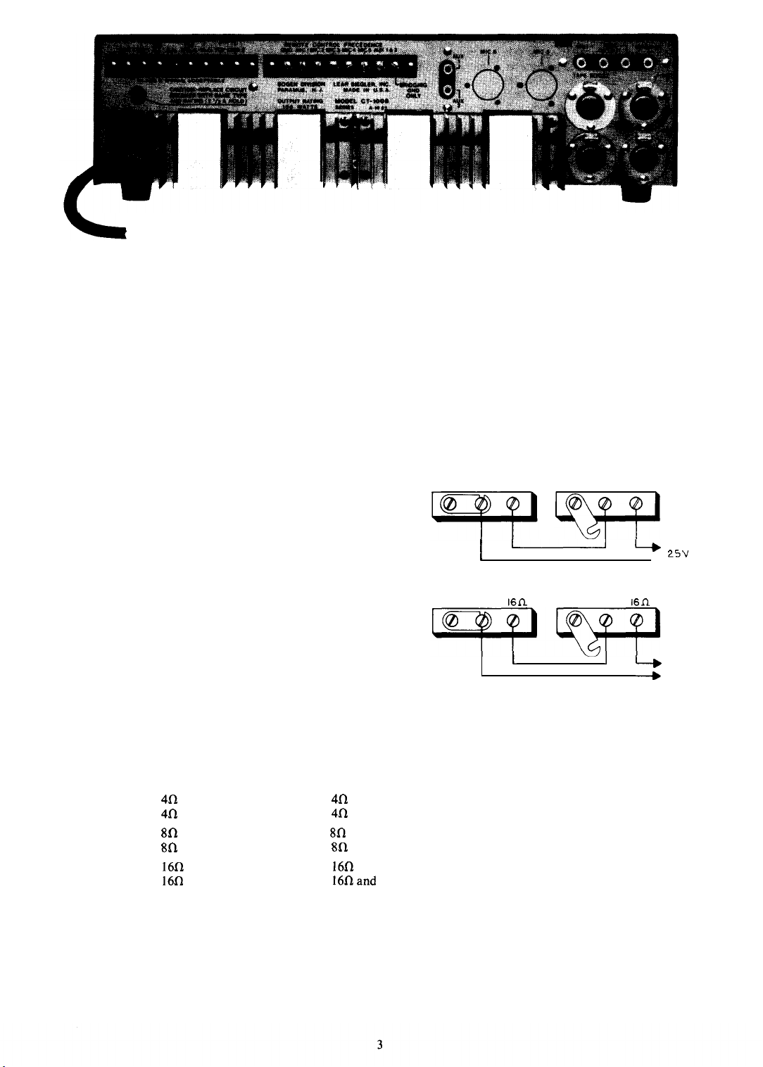
Figure 2 -Rear Panel,
CT100B
OUTPUT CONNECTIONS
SPEAKERS: Output connections are available on the rear panel
terminal strip for 4 (CT-lOOB), 8,16-ohm speakers, 25 volt centertapped and 70 volt lines. Connections necessary are listed in Table
I. Class 2 wiring may be used.
For detailed information see Installation Manual No. 54-5001
furnished with the amplifiers.
TAPE OUTPUT: A tape recorder may also be driven from the
TAPE OUTPUT jack on the amplifier. In this case, the output is
not subject to the master volume and equalization settings of the
amplifier and is controlled at the tape recorder. A patch cord
terminated in an RCA phono plug is connected between the TAPE
OUTPUT jack
BOOSTER OUTPUT: The amplifier may be used to drive a
booster amplifier. Connect a patch cord with an RCA phono plug
from the BOOSTER jack on the rear pane1 of the amplifier to the
high impedence input of the booster amplifier. The output at this
jack is controlled by the amplifier’s volume and equalization
controls.
WMT-1 OUTPUT: This receptacle is used to accommodate a
Bogen
accessory which provides connections to a 500/600-ohm
telephone line. (Refer to Accessories Section).
on the amplifier and the input of the tape recorder.
CONNECTING AMPLIFIERS IN SERIES
Pairs of the same amplifier models can be connected in series to
effectively double the power output into the same loadline, as well
as increase the input capacity. See Figure 3 for connection
diagram. Be certain to remove the link between COM and GND of
amplifier No. 2.
Tone and master volume controls of both amplifiers should be
at the same setting to assure that each amplifier will share the load
equally.
Connect a single conductor shielded cable, terminated in an
RCA phono plug at each end, between the rear panel BRIDGING
receptacles and BRIDGING GND terminal of both amplifiers.
This assures that any input will have equal amplification.
AMPLIFIER I
GND COM
AMPLIFIER
GND COM
A74-2031-01
25VCT
’
I
I
CT60B OR
1
161l
1 I
CT60B
Figure 3- Connecting Like Amplifiers in Series
AMPLIFIER 2
GND COM
CT100B
AMPLIFIER 2
GND COM
OR
CT100B
25VCT
I
“r
\I
L3”
16fl
L_t
7ov
TABLE 1
Models
CTlOOB
Both models
Both models
Both models
Both models
*Also see text under “Output Connections”
Speaker Line
4fI Unbalanced
4fl
Balanced
8fI Unbalanced
80
Balanced
16fI
Unbalanced
16fI
Balanced
25V Unbalanced
25V Balanced
25V Balanced, CT gnd.
70V Unbalanced
70V Balanced
-
OUTPUT CONNECTIONS
Terminal Connections*
4n
and COM 1
4fl
and COM
8fl
and COM 1
8G and COM 1
16fI
and COM 1
16fIaand
COM
25V and COM 1
25V and COM
25V and COM 1
1
1
1
Close link between COM 1 and GND
Open link between COM
Close link between COM
Open link between COM 1 and GND
Close link between COM 1 and GND
Open link between COM 1 and GND
Close link between COM
Open link between COM 1 and GND
Connect jumper between 25V CT and GND
Open link between COM 1 and GND
70V and COM 2
70V and COM 2
Add jumper between COM 2 and GND
No jumper required
Other Connections
1
and GND
1
and GND
1
and GND
Page 4

ACOUSTIC EQUALIZER:
to “tune” the amplifier to the room in which the sound system is
used, so that the amplifier will operate at a substantially higher
output before acoustic feedback occurs. Ten slide controls, located
on the front panel, boost or attenuate the output at preferred IS0
center frequencies-80,
and 5000 Hz-to compensate for varying room acoustics.
Microphone placement may also cause feedback or howling at
or near some of these frequencies. If so, feedback can be greatly
attenuated by setting the slidecontrolfor that particular frequency,
as described below.
The Acoustic Equalizer permits you
125,200,315,500,800,
1250,2000,3150
ACOUSTIC EQUALIZER FILTER ADJUSTMENT
MICROPHONE SOURCE:
The following adjustments of the slide filter controls will permit
“tuning” the system so that the output level is substantially higher
before acoustic feedback (“squeal” or “ringing”) occurs.
1. Set MIC controls and MASTER control to zero (counter-
clockwise).
2.
Set all slide controls to center (flat) position, with speakers
connected to the amplifier and microphone(s) in normal operating
location(s).
3. Turn the appropriate MIC volume control half-way up,
leaving the three other MIC volume controls at zero.
4.
Advance MASTER control slowly until feedback (“ringing”
or “squeal”) is heard.
5. If the feedback sound is high-pitched, one of the five high
frequency filter controls-800 Hz to 5 KHz-will be most effective
low-end
in its elimination. Likewise, a
low frequency filter.
6.
Individually, move each filter control
position to bottom and back to center while listening for change of
feedback. The control which eliminates feedback with the least
movement should then be moved down only as far as is necessary
to eliminate the feedback.
7. Having eliminated the first feedback condition, slowly
increase the MASTER control until feedback is heard again.
Repeat the procedures of steps
8.
If the position of the microphone is changed or if additional
microphones are used some adjustment to these controls may be
necessary.
9.
Output level, reduced because of attenuating one frequency,
may be partly restored by boosting the adjacent frequency filter
control toward maximum.
If feedback
be used to improve the voice quality and intelligibility of the paging system. In most cases, the 80
Hzcontrol should
while the 2 KHz, 3150 Hz and 5 KHz should be
moved to ward maximum for improved response.
Each system, depending on the speakers
room acoustics, will require some experimentation with the controls for optimum results.
10.
Note and record the settings of the individual filter controls
and the MASTER control. These settings are generally applicable
to all four MIC input channels. Rubber washers (supplied) can be
placed on the slide controls to avoid accidental movement. To do
so, pull the slide control knobs off the shafts, insert the rubber
washers, and replace the knobs securely.
is not a problem, the controls should
be placed
tone will be controlled by a
slowly
from the center
5,6.
in
minimum
position
used and
COMPRESSOR LIMITER: The COMPRESSION control
(which is screwdriver-adjustable through the front panel-to
avoid tampering) is used to provide relatively uniform output from
the amplifier, regardless of variations in the input levels. This is
particularly important in speech applications, where a microphone
may be used by a number of people with varying voices and
microphone techniques. It is also useful for musical programs,
particularly when handling background music.
The COMPRESSION control is turned clockwise to reduce the
output range for a given variation in input range. Turn the control
counterclockwise to increase the output range. To remove
compression and restore the normal full range of the amplifier,
turn the control fully counterclockwise.
To determine the optimum setting of the COMPRESSION
control for speech applications, proceed as indicated below. (For
music, the setting will generally be lower than for speech.)
Set the COMPRESSION control fully counterclockwise. Set
the MASTER volume control to the highest level likely to be
required. Use a level setting that will permit you to pick up clearly
spoken inputs in a low voice at a distance of three feet on axis from
the microphone. However, do not set the volume level so high as to
produce feedback or howling.
Then, speaking in a loud voice directly into the microphone,
turn the COMPRESSION control clockwise to the point where
the output of the amplifier is reduced to the same level as obtained
above. The MASTER control can be used to vary the overall
volume without upsetting the COMPRESSION adjustments.
OPERATION
POWER: This switch applies power to the amplifier. It does not
control any associated equipment which may be connected to the
auxiliary power receptacle on the rear panel. The POWER
indicator lamp will go on to show that power has been applied to
the unit.
MIC
VOLUME: The four individual MIC volume controls are
used to adjust the level of each microphone input channel. The
control is turned clockwise (to the higher numbers) to increase the
volume and counterclockwise to reduce it.
AUX VOLUME:
either of the two auxiliary inputs and it controls the volume of the
selected auxiliary input. To select the AUX 1 input, rotate the
control counterclockwise past the center position. Turning this
control counterclockwise to the higher numbers increases the
AUX 1 volume. To select the AUX 2 input, rotate the control
clockwise past the center position. Turn the control more clockwise to increase the AUX 2 volume.
If the auxiliary input is not to be used, set the control to the
center position. The center position is indicated when the triangle
on the control knob coincides with the vertical line between the
AUX 1 and AUX 2 designations.
MASTER: This control is used to regulate the overall volume of
the amplifier, which may include the mixed output of two or more
input channels. To set this control, rotate it to the center position,
then set the individual MIC and AUX controls to the highest level
likely to be used and consistent with the operation of the limiter
compressor. Adjust the MASTER control to the desired listening
level for the mixed output.
This control serves a two-fold purpose. It selects
4
Page 5

ACCESSORIES
CAUTION
The installation of internal accessories requires
the removal of the cover, which presents an
electrical shock hazard. For this reason, these
accessories should be installed by
technicians only.
PMM-2B
MICROPHONE MODULE: The
Microphone Module is a preamplifier designed to provide two
additional microphone channels for the amplifier. Each preamplifier channel has its own volume control and will accommodate either low-impedance balanced or high-impedance
microphones. These added channels have all the characteristics of
the basic channels, and the same accessories are applicable to
them, except that provision for remote control, and precedence is
made on one of the two additional inputs.
The Model PMM-2B mounts through the front panel of the
CT-B amplifiers. Holes are incorporated in the front panel of the
amplifiers to receive the control shafts of the PMM-2B unit.
To install the PMM-2B in the amplifier:
1.
Remove the four screws on each side of the amplifier cover
and lift it away from the chassis.
2.
Remove the plug buttons on the front panel of the amplifier
where the Volume Controls for MIC
inserted.
3. Open accessory bag furnished with the PMM-2B.
4.
Two metal brackets are furnished to support the rear of the
preamplifier circuit board assembly. Note two predrilled holes
and locator holes in the chassis directly below and at the rear of the
circuit board assembly. Turn the chassis on one side. Position one
bracket, locating tongue into locating hole in chassis. Secure with
machine screws and nuts supplied. Repeat this procedure with the
other bracket. Turn the chassis right side up.
Before installing the circuit board assembly, note that the
PMM-2B is shipped for low-impedance microphone inputs. For
high impedance microphone input connections, see Note 3 on the
schematic diagram.
5. Use a screwdriver to pry out two knockouts at the rear
panel of amplifier chassis.
6.
Remove the push-on lugs from the PMM-2B printed circuit
board (pins 1 through 6). Guide the orange cable through the
MIC 6 opening on the rear panel and the yellow cable through the
MIC 5 opening; reconnect the push-on lugs to pins 1 through 6.
The following table lists correct connections.
Color
MIC 6 (Orange Cable)
Red
Black
White
MIC 5 (Yellow Cable)
Black
Red
White
7.A .047
disc capacitor is attached to the MIC 5 microphone
connector. Remove the loose end of the wire from the sleeve on the
yellow cable and connect it to the ground lug on the tie strip
directly below MIC 6 connector.
8. Using the six mounting screws provided, secure the micro-
phone connectors to the rear panel with the PUSH tabs at the top
(same position as MIC 1 and MIC 2).
9. A brown wire is connected to pin 10 on the PMM-2B
printed circuit board. Connect the other end of this wire to the
terminal lug inside the rear panel, corresponding to the screw
terminal marked MIC 5 PRECEDENCE on the rear panel.
10. Insert the four-wire Molex plug into the four-prong male
socket
Jl
on the amplifier’s main printed circuit board. Note that
the four-wire plug can be inserted one way only. Do not twist or
turn.
qualifed
Bogen
PMM-2B
5
and MIC 6 are to be
PMM-2B
Term. No.
1
2
3
5
4
6
-
WMT-1
MOUNT
0
FRONT
Figure 4
A74-2923-01
Mounting Holes for WMT-1
-
ING
HOLES
11. Install the PMM-2B, component side down, inserting
control shafts and bushings through holes in front panel. Run up
two hex nuts over bushings of control shafts.
12. Press the control knobs onto the flatted volume control
shafts. Replace the amplifier cover, using the original screws
provided.
WMT-1 LINE-MATCHING TRANSFORMER:
The
Bogen
WMT-1 line-matching transformer provides an impedance match
between the amplifier and a 0 level, 500/600-ohm line. This may be
a telephone line connected to the switchboard for internal paging
or used with a wired music system. No soldering is required to
connect the WMT-1 to the amplifier.
To connect the input from a balanced 500/600-ohm telephone
line, remove the amplifier cover and mount the WMT-1 using the
mounting holes provided on the chassis (see Figure 4). Connect the
input line to the three-screw terminal board on the WMT-1.
Connect the phono plug on the WMT-1 cable to the AUX 1 or
AUX 2 jack on the rear of the amplifier. If these jacks are being
used for other sound inputs, the WMT-1 may be connected to one
of the MIC inputs. In order to do this, the WMT-1 wiring must be
modified as described in the instruction sheet supplied with the
WMT-1.
To connect the amplifier output to a 500/600-ohm telephone
line, remove the amplifier cover and mount the WMT-1 using the
mounting holes provided in the chassis (see Figure 4). Connect the
500/600-ohm line to the three-screw terminal board on the
WMT-1. Connect the phono plug on the WMT-1 cable to the
WMT-1 (OUTPUT) jack (next to the BOOSTER jack) on the rear
of the amplifier.
RVC-2B
RVC-2B to the Remote Control/ Precedence terminal
REMOTE VOLUME CONTROL: Connect the
(TSlOl)
on
the rear of the amplifier. Connect one lead from the accessory to
the appropriate MIC or AUX terminal and the other lead to
GND. Complete installation instructions are supplied with the
RVC-2B accessory.
MODEL TG-4B MULTIPLE TONE GENERATOR:
TG4B
Multiple Tone Generator is capable of generating four
Model
distinct signals: pulsed tone, slow whoop, repeating chime, and
steady tone. Each of these four signals may be applied continuously
or limited to a double burst (single burst only of the steady tone)
for alarm signalling or pre-anouncement. Signals are triggered by
an external device that provides a contact closure. Both tone level
and pitch are adjustable. May be powered from 15-26 VDC
source, or use optional
Bogen PRS-40
Power Supply for 120 VAC
operation.
5
Page 6

MODEL RPK-33A RACK PANEL: The
designed to mount the CT-B amplifiers in a standard 19” sound
rack. Instructions are furnished with the RPK-33A.
CON-2
MICROPHONE CONNECTOR:
a 3-pin male microphone connector, similar to the Cannon
XLR-3-12C or the Switchcraft A3M. The
the PMM-2B microphone connectors are designed to accept mic
inputs with these terminations.
RPK-33A rack panel is
The Bogen CON-2 is
CT60B, CT100B
and
use a heat sink (such as a small alligator clip) between the
component and the source of heat. Unless you are experienced in
the removal of IC micromodules, do not attempt to remove them
since excessive heat can damage an IC and/ or the printed circuit
board. If you are certain that an IC is defective, the easiest method
of removal is to cut the leads off close to the component and
unsolder the leads individually. If you are not certain an IC is
defective, the use of a low-wattage, vacuum-type desoldering tool
(such as Ungar Type 7800) is advised.
TP SERIES TUNERS: The
provide FM/ AM or FM/ AM/ FM-Stereo reception of superior
signal quality with precise tuning indicators. Output jacks permit
connection to an amplifier and/ or a tape recorder. Rack mounting
kits are also available for these units.
Bogen
TP Series solid-state tuners
MAINTENANCE
CAUTION
There
are no user replaceable parts within the
unit. Have all internal servicing done by a
qualified technician.
CIRCUIT BREAKER
If the circuit breaker opens, the ac power lamp will go out and
the amplifier will have no output, but there will be power at the
AUX POWER receptacle at the rear panel. Set the ac power
switch to off and
breaker to reset it. Return the ac power switch to on. If the breaker
trips again, do not attempt to reset it but have the trouble
investigated by a qualified technician.
THERMAL BREAKER
If the thermal breaker opens, there will be no audio output but
the ac power lamp will remain on. Wait approximately two
minutes for the breaker to reset. If the breaker resets and then
opens again, investigate the cause of the temperature overload.
This may be due to improper connections at the output terminals
or to excessive environmental heat with inadequate ventilation.
The thermal breaker will open when the temperature at the output
transistor heat sink reaches 105” C
REMOVING PC BOARD FOR SERVICING
To remove the PC board:
1. Remove all knobs and nuts from the front panel controls.
2. Remove four PK screws from the slide control mounting
bracket (inside the front panel).
3. Remove two PK screws at either end (toward the front) of
the PC board.
4.
Disengage the four nylon standoffs that support the rear of
the PC board by raising the board gently with one finger while
depressing the standoff locking tab with a screwdriver blade or
small pliers.
5. Lift the rear portion of the PC board so as to clear the
adjacent components and guide it toward the rear of the unit for
removal.
REPLACING COMPONENTS
Improper soldering may damage components or
the printed circuit board, and such damage can
void the warranty.
Many semiconductor components are soldered in place to
ensure maximum reliability. When soldering transistors or diodes,
momentarily
CAUTION
depress the red button on the circuit
(221°
F) on all models.
REPLACING TRANSISTORS
CAUTION
AN transistors are soldered to ensure maximum
reliability. When soldering leads, use a heat sink
(such as a small alligator clip) between the
transistor and the source of heat.
When replacing the driver transistors, press a small screwdriver
blade into the side of the
clip. Draw the clip and screwdriver off the metal tab on the driver
transistor. Reverse the procedure to install the clip on the
replacement transistor. Since the U-clip heat sink is a spring clip,
avoid spreading the jaws too wide.
When replacing the output transistors, clean all foreign matter
from the heat sink, insulator, and transistor. Brush a light coating
of silicon compound, such as Dow Corning No. 340, to completely
cover both surfaces of the insulator (Part No.
the insulator between the heat
Use the original transistor mounting hardware to mount the
replacement transistor.
U-clip
heat sink to spread the jaws of the
sink and
the replacement transistor.
16-9278-01).
Place
BOGEN SERVICE
We are interested in your Bogen amplifier for as long as you
have it. If trouble ever develops with your unit, please do not
hesitate to ask our advice or assistance. Information can be
obtained by writing to Service Department, Bogen Division/ Lear
Siegler, Inc., PO. Box 500, Paramus, New Jersey 07652.
When communicating with us, give the model number and
series designation of your unit. Describe the difficulty encountered
and the effects each operating control has upon the symptoms of
trouble. Include details on electrical connections to associated
equipment, and list such equipment. When we receive this
information, we will send you service information if the trouble
appears to be simple. If the trouble requires servicing, we shall send
you the name and address of the nearest Bogen authorized service
agency to which you can send your unit for repairs.
When shipping your unit, pack the amplifier well, using the
original shipping carton or a similar container and filler material
to prevent damage in transit. Send the unit, fully insured and
prepaid, via UPS or any responsible carrier. The unit will be
promptly repaired and returned to you collect.
REPLACEMENT PARTS
Most components used in the amplifier are standard parts
available through reputable parts suppliers. The parts listed here
may be obtained from
directly from the factory. When ordering a part, specify a part
number, the model of the unit, and give the series designation,
which is a letter followed by numbers, printed on the chassis. For
parts on circuit boards, also give the component board assembly
number, which begins with “45”.
When replacing transistors, use those made by the specified
manufacturers. Transistors from other suppliers may not be
satisfactory. Certain resistors must be Allen-Bradley products.
These are designated by “AB” on the schematic diagram.
Bogen
distributors, service agencies or
6
Page 7

Page 8

Page 9

Ref. No. Part No.
45-7176-05
C18,81-83 79-008-046
C28,3
I
79-008-049
C34,7
1
79-008-058
c35
C29,36,73
C56
C61
C63
C65,66,75
C68
C70
C80
CR1,2,4-6
CR3
ICI-5
IC6-8
IC9
IC10
Ql-l0, 12,
QlY
Q13
Ql4
Q16
Q17 96-5356-0 1
R53,55-57777-001-808
Rlll
R140 77-001-812
79-008-057
79-008-033
781104-l 50
79-120-005
79-008-044
79-008-062
78404-l 52
79-119-001
79-119-015
96-5333-01
96-5344-08
96-5436-O
96-5488-O
96-5437-O
96-5489-0
96-5213-01 96-5 176-O
96-5298-01
96-5283-01
96-5357-01
77-007-003
Description
P.
C. Board
P. C. Board Assembly
Cap., Elect.,
Cap., Elect.,
Cap., Elect.,
Cap., Elect.,
Cap., Elect.,
Cap., Dura Mica, 680pF
Cap., Elect., Low Leakage,
Cap., Elect.,
Cap., Elect.,
Cap., Dura Mica, 820pF
Cap., Elect., 470µF 63V
Cap., Elect.,
Diode, 400 prv
Zener Diode,
I. C., HllF3
1
I. C., LM348N
1
I. C., MC78L24CP
1
1. C., LF356N
1
Transistor,
1
Transistor, MPS6518
Transistor,
Transistor, MPS-A55
Transistor, 2SD389P/2SD313D/
TIP3lA
Transistor, 2SB512P/2SB507D/
TIP32A
Control, 1 megohm
Trimpot, 50kilohms
Control, 200 kilohms
22µF 35V
5OOµF
lOµF,
50µF 5OV
2.2µF
1OOOµF
lOOµF,
33OOµF
@
3OV,
2N5089
SPSl910
35V
50V
16V
35V
50V
63V
1
A
2W
2.2µF
50V
Ref. No. Part No.
Rl49,152 76-107-096
T1-4
-
ClOl-104
Cl06
CBlOl 94-0023-05
CB102 94-0014-07
4101,102 96-5385-01
QlOl-104
R201
R202,203 76-116-003
R202,
204-20676-l 16-003
R207
R80-89 77-001-826
SW101 8 l-009-035
TlOl 83-809-000
T102
83-058-000
85-1287-01
70-93
13-O
96-5241-01
79-509-052
79-509-053
94-0023-08
96-5397-01
96-5385-01
96-5397-01
77-001-825
75-742-101
83-814-010
83-423-000
83424-000
14-9088-01
03-0670-0
03-0671-0l
03-0628-03 Slide Control Knob (Black)
1
Description
.82
Resistor,
Mic Input Transformer
4-Point Header
1
Heat Sink Clip
Chassis
Diode, 300 prv
Cap., Elect.,
Cap., Elect.,
Circuit Breaker,
Circuit Breaker,
Thermal Breaker,
Transistor,
Transistor,
Transistor,
Transistor,
Control,
Resistor,
Resistor,
Resistor, 100 ohms, 7W
Slide Control, 50 kilohms
Lighted Rocker Switch,
Power Transformer
Power Transformer (CTlOOB)
Output Transformer
Output Transformer (CTlOOB)
Foot
Knob (O-10)
Knob (5-O-5)
ohms, 2W
@
3A
2OOOµF
3000µF
1.6A (CT60B)
2.5A (CT100B)
105°
2N3055H
2N3055
Solitron
2N3055H
2N3055
Solitron (CTlOOB)
2 megohm
.27
ohms, 7W
.27
ohms, 7W (CTlOOB)
75V
(CT60B)
75V (CTlOOB)
C
RCA, or
(CT60B)
RCA, or
(CT60B)
lOA,
(CT60B)
(CT60B)
SPST
 Loading...