

Page 1

A DIVISION OF LEAR SIEGLER, INC.
AMPLIFIERS
Bogen
Amplifiers are versatile, silicon-transistor
amplifiers designed for professional-quality sound reinforcement requirements. Model CT-35 is rated at 35 watts,
Model CT-60 at 60 watts and CT-100 at 100 watts output.
Four high-impedance microphone inputs are provided,
each convertible for use with low-impedance microphones.
A simple modification converts inputs to low-impedance
unbalanced; balanced inputs require accessory plug-in
transformers. Two mic inputs and one auxiliary input may
be remotely controlled or muted for announcements over
another mic channel. The same two mic inputs may be converted to accept a magnetic source, i.e., turntable or tape
player. Two auxiliary inputs with fader control are provided, as well as a bridging input.
Acousta-Master amplifiers feature the
acoustic equalizer filter circuit, which provides a means of
boosting or attenuating any of five selected frequencies to
suit individual room acoustics. An electronic limiter circuit
provides uniform output regardless of wide variations in the
input level. With this capability, all paging calls can be
transmitted with the same volume and clarity.
An output terminal strip and connectors at the rear of
the amplifier provide standard speaker impedance taps, as
well as connections for
There is also a bridging output for feeding a tape recorder.
Bogen
line input and output connections, remote volume control,
and channel override facilities. Further information is
contained in the Accessories section.
The amplifier operates from a
source. A three-prong line cord provides automatic ground-
ing when connected to a three-wire power outlet. The
power line is protected by a circuit breaker, and the output
transistors by a thermal overload device, which shuts off
the unit when the temperature of the heat sink rises
excessively.
Acousta-Master@ CT Series Public Address
preamp-mixer-
Bogen
built-in
25volt
or
70-volt
balanced lines.
accessories provide the amplifier with telephone
105-125
volt,
50/60
Hz
Models CT
35/60/100
INSTALLATION
UNPACKING
The amplifier was carefully checked before leaving
factory. Inspect shipping container and unit carefully for
indications of improper handling. If the unit has been
damaged, make an immediate claim to distributor from
whom it was purchased. If the amplifier was shipped to
you, notify transportation company without delay and
place your claim.
POWER AND GROUNDING
The ac line cord has a three-prong plug which should be
plugged into a three-wire grounded, 120 volt, 60 Hz outlet.
As it is important to ground the amplifier, where a threewire outlet is not available, use an adapter (e.g., Leviton
No. 5017) and connect the grounding pigtail to the screw
securing the wall plate. If the wall plate screw is not grounded, connect a wire from the GND terminal of the amplifier
to a suitable ground.
AUXILIARY POWER
The auxiliary power receptacle on the rear chassis (see
figure 1) is a three-wire grounded outlet, which can supply
power to accessory sound equipment. When connecting
associated equipment with a three-prong cord, appropriate
grounding is accomplished when the amplifier line cord is
properly grounded.
Use the ON/OFF switch on the phonograph for turning
off a record player connected to the auxiliary receptacle, as
use of the amplifier power switch could cause flats to
develop on the idler wheel of the phonograph.
Be sure that the auxiliary components do
not draw more than 250 watts on the CT35
and CT 60, and 500 watts on the CT1 00.
Prmted in
USA 8104
54-5629-l 4
Page 2
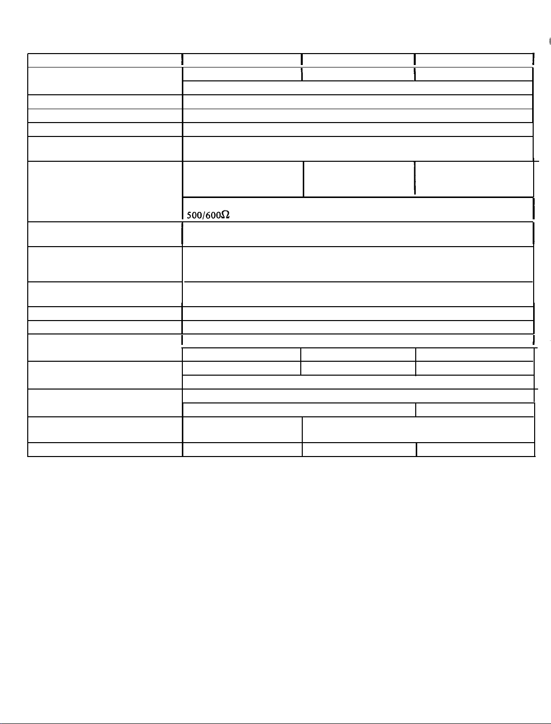
TECHNICAL SPECIFICATIONS
I
POWER OUTPUT (RMS at 1000Hz)
FREQUENCY RESPONSE
REGULATION
HUM & NOISE (below rated output)
SENSITIVITY
OUTPUTS
OUTPUT CONNECTIONS
INPUTS
CONTROLS
FILTERCONTROLACTION ±
COMPRESSION
LINE FUSING
SEMICONDUCTORS
POWER CONSUMPTION
DIMENSIONS
SHIPPING WEIGHT
(for rated output)
MIC, 60
Hi Z MIC, 3 mV; Low Z Bal MIC, 0.3
30 mV; AUX 150
4, 8,
Bridging, 30
500/6OOa telephone line input or output with WMT-i optional accessory.
I
2 Quick disconnect type sockets with plugs provided, in addition to screw-type
terminals, tape/booster jack, and provisions for WMT-1.
I
4 Hi Z MIC inputs, each convertible to Low Z Bal or Unbal MIC; 2 AUX inputs with
fader control; MIC 1
telephone line with optional WMT-1 accessory; 3 inputs for remote volume control.
4 MIC Volume, AUX 1, AUX 2-fader, MASTER VOLUME, 5 Equalizer Filter Slide
Controls. 1
10
dBB
5 milliseconds attack time, 2 seconds decay time, max. compression 30
I
18
silicon transistors 18 silicon transistors 20silicon
16-3/8”W
(41.6cm x 32.4cmx12.lcm)
19 lbs. (8.6 kg)
CT35
35 watts
dB
for both low and high impedance; AUX 70
mV
16
ohms 8,16
25V CT
7ov 7ov
mV;
Tape, 0.68 V. TAPE/BOOSTER/BRIDGING outputs,
&
Compressor.
variationatthefollowingfrequencies:
0.93 A Hold
2 Zener Diodes; 8 Silicon Diodes (10 in
0.86A, 96W
x
12¾”D
x
I
I
@
less than 2% total harmonic distortion
50Hz to 15kHz ±2dB
4 convertible to MAG input; Bridging input; 500/600 ohm
1 Power Switch.
Resettable Circuit Breaker
4¾”H
CT60
60 watts
2
dB
mV;
Low Z Unbal MIC 0.3 mV; Bridging Input,
ohms
25V
CT
1.65 A Hold 2.5 AHold
120 V AC,
221bs. (9.9 kg)
50/60
1.6A,
170w
16-3/8”W
(41.6cm x
I
I
dB;
Fundamental, 80
I
80Hz,300Hz,1 kHz,3kHz,10kHz.
CTl00)
Hz
x
13 3/4”D
34.9cm
CT100
100 watts
4, 8,,16ohms
25V
7ov
dB
2.9A, 300W
x
4 3/4”H
x 12.lcm)
26 lbs. (11.8 kg)
dB
CT
transistors
I
I
I
I
INPUT CONNECTIONS
HIGH IMPEDANCE MICROPHONES: The amplifier is
shipped in a configuration for direct connection of high
impedance microphones (50k ohms) to the four MIC input
receptacles of the amplifier. The microphone lead should be
a single-conductor shielded cable under 35 feet long and
terminated in a Cannon XLR-311C connector
No. 85-0124-01) as shown in figure 2.
In the event jumpers on the printed circuit board have
been rearranged and must be returned to the configuration
for direct connection of high impedance microphones,
connect the two jumpers involved as follows: the first
jumper between terminals 11 and 19, and the second
(Bogen
Part
be-
tween 8 and 18. Three jumpers are not involved and are
stored by connecting both ends to an assigned terminal: the
first jumper on terminal 20, the second on 24, and the third
on 25.
BALANCED LOW-IMPEDANCE MICROPHONES:
impedance accessory transformers are required to permit
the amplifier to accept inputs from microphones rated from
50 to 600 ohms. Before connecting microphone, insert
appropriate plug-in transformers and reset jumpers adjacent
to transformer sockets as described in the Accessories
tion. Use a two-conductor shielded cable for the
phone lead, terminated in a Cannon XLR-311C connector,
as shown in figure 3.
-2-
Low-
+
micro
sec-
,
Page 3
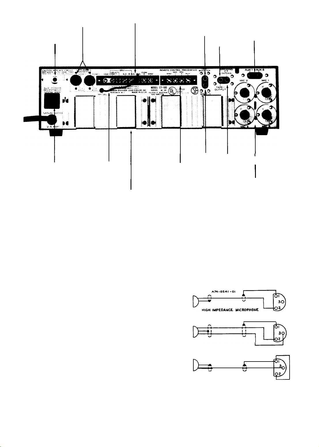
CIRCUIT
BREAKER
SPEAKER
SOCKETS
OUTPUT
TERMINALS
TAPE/BOOSTER
TAPE
OUTPUT
AUX
INPUTS
I
AUX
POWER
Note:
Heat sink for Model CT-35
is an aluminum plate.
IMPEDANCE
SELECTOR
I
I
REMOTE/PRECEDENCE
TERMINALS
I
HEAT SINK
Figure 1 - Rear Panel, CT-100
I
I
WMT-1
OUTPUT
I I
BRIDGING
I
I
MIC INPUTS
UNBALANCED LOW IMPEDANCE MICROPHONES:
Jumpers with push-on connector lugs are mounted on the
printed circuit board assembly for use in converting the
MIC input channel circuits. See note 4 on the schematic
diagram, figure 6. To convert MIC 1 and 4 for unbalanced
low impedance use, connect jumper between pins 20 and
2 1; to convert MIC 2 and 3, connect jumper between pins
25 and 26. As shown in figure 2, connect a jumper between
terminals 1 and 2 of the connector and wire microphone to
pin 3 of the plug.
AUXILIARY INPUTS: Two auxiliary inputs are provided
for high-level, high impedance inputs. these may be used to
connect a radio tuner, tape recorder, or turntable utilizing a ceramic cartridge. An input signal of 0.15 volts is
required to obtain full output from the amplifier.
Use single-conductor shielded cable terminated in an
RCA phono plug for connecting auxiliary component. If
hum is experienced after making connections, run a ground
wire between the chassis of the auxiliary unit and the GND
terminal on the amplifier.
BRIDGING: The amplifier may be bridged to a second
Bogen
CT amplifier to double the number of inputs. Connect a single-conductor shielded cable, terminated in an
RCA phono plug at each end, between the rear panel
BRIDGING receptacles of the two amplifiers. Any input to
either amplifier will then be fed through and available at
the output of both amplifiers. The amplifiers must each
feed separate speaker systems.
When two amplifiers are bridged together,
any adjustment of the MASTER, COMPRESSION or Acoustic Equalizer controls in
one amplifier will not affect the output of
the other amplifier.
:
Figure 2
(CONNECTION
LOW IMPEDANCE MICROPHONE
LOW IMPEDANCE MICROPHONE
-
Connecting Microphone Cable Connector
SAME
FOR
BALANCED
UNBALANCED
MAG
PHONO)
XLR-311C
XLR-311C
2
J
XLR-311C
-3-
Page 4

MAG PHONO: The output of a phonograph employing a
magnetic cartridge may be connected to the MIC 1 and 4
receptacles on the rear panel. Use a single-conductor
ed audio cable terminated in a Cannon XLR3
shield-
11C connector as shown in figure 2 (connections same as high impedance mic). A magnetic tape head may also be connected
in this manner.
To provide the necessary equalization for magnetic
phono and tape head inputs, the Berg terminal jumpers on
the printed circuit board must be connected as indicated in
note 3 on the schematic diagram. Connect a jumper between pins 21 and 22 and between pins 23 and 24.
OUTPUT CONNECTIONS
SPEAKERS: For installations where speakers will be con-
nected permanently, output connections are available on
the terminal strip at the rear of the amplifier for 4, 8, and
16 ohm speakers and
made for an unbalanced line or for a balanced line with or
without center-tap grounding. Make speaker line connections
as shown in Table 1.
Impedance indicated in Table
speaker sockets on the rear panel. Two quick-disconnect
plugs (Bogen 85-0147-01) are furnished with the amplifier
to make connections to these sockets. Wiring of the speaker
output plug is shown in figure 3. When the speaker sockets
are used, connect the wired plug to either socket. For
balanced. 4, 8, 16 ohms
impedance selector lead to the speaker system impedance
terminal, and leave the link connected between COM
GND terminals. A balanced output is available by removing the
link.
For 70 volt constant voltage systems, see Table 1. For
detailed information see installation manual No.
furnished with the amplifier.
To minimize shock hazard, Class I wiring as
defined in local building codes should be
used for 70-volt outputs. All other outputs
may use Class 2 wiring.
CONNECTING AMPLIFIERS IN SERIES: Pairs of Bogen
CT amplifiers of the same power rating can be connected in
series to effectively double the power output into the same
speakers. See figure 4 for connection diagram. Be certain to
remove the link between
2.
25volt
lines. Connections may be
1
is also available at two
and 25-volt
operation, attach the
COM 1 and GND of amplifier No.
FOR 70V
OPERATlON
un-
1
and
54-5001,
Connect a single conductor shielded cable, terminated in
an RCA phono plug at each end, between the rear panel
BRIDGING receptacles of both amplifiers. This assures that
any input will have equal amplification.
AMPLIFIER 1
GND
COMI
25VCT
AMPLIFIER 1
GND COM 1
A74-2031-01
l6n
CT60 AND CT
GND
ALL UNITS
AMPLIFIER 2
GND COM 1
AMPLIFIER 2
COMl
25VCT
1
100
L+25V
b
16n
Figure 4 - Connecting Amplifiers in Series
Both amplifier tone and master volume controls must be
at the same setting to assure that each amplifier will share
the load equally.
TAPE/BOOSTER OUTPUT: The amplifier may be used to
drive a tape recorder or a booster amplifier. Connect a
patch cord with an RCA phono plug from the TAPE/
BOOSTER jack on the rear panel of the amplifier to the
input of the tape recorder or booster amplifier. The output
at this jack is controlled by the amplifier’s volume and
equalization controls.
TAPE OUTPUT: A tape recorder may also be driven from
the TAPE OUTPUT jack on the amplifier. In this case, the
output is not subject to the master volume and equalization
settings of the amplifier and is controlled at the tape
recorder. A patch cord terminated in an RCA phono plug is
connected between the TAPE OUTPUT jack on the amplifier and the input of the tape recorder.
WMT-1 OUTPUT: This receptacle is used to accommodate
a Bogen accessory which provides connections to a
600-ohm telephone line.
500/
zil-J=
FOR 25V OPERATION
OR SELECTED IMPEDANCES
3c---1-
-!
Figure 3-Speaker Output Plug Wiring
ACOUSTIC EQUALIZER: The Acoustic Equalizer permits
you to “tune” the amplifier to the room in which the
sound system is used, so that the amplifier will operate at a
substantially higher output before acoustic feedback occurs. Five slide controls, located on the front panel, boost
or attenuate the output at five selected frequencies-80 Hz,
300 Hz, 1 KHz, 3
kHz,
and 10
kHz.
Varrying room acoustics or microphone placement may cause feedback or howling at or near some of these frequencies. If so, feedback can
be greatly attenuated by setting the slide control for that
particular frequency as described below.
-4-
Page 5

TARI
F
1-f-U
._I__ . __.. _.
ITPI IT
CONNECTIONS
Models
CT35 & CT100
All models
All
All
All
*Also see text under “Output Connections”
ROOM EQUALIZATION: With speakers connected and
Speaker Line
4S2
Unbalanced
4n
Balanced
8n
Unbalanced
8n
Balanced
16n Unbalanced
16n
Balanced
25V Unbalanced
25V Balanced
25V Balanced, CT gnd.
70V Unbalanced
70V Balanced
Terminal Connections
4n
and COM 1
4n and COM
8n
and COM 1
8n
and COM 1
160
and COM 1
16n
and COM 1
25V and COM 1
25V and COM 1
25V and COM 1
Pins 2 and 3
Pins 2 and 3
one microphone in normal operating location, turn amplifier on and proceed as follows:
1. Connect microphone to appropriate MIC input of
amplifier.
2. Set all five acoustic filter controls to zero (center
position).
3. Turn MIC volume control half-way up and the three
other MIC volume controls to zero.
4. Advance MASTER volume control slowly until
feedback is heard.
5. Note the frequency of the feedback tone, and determine which of the five selected frequencies on the
Acoustic Equalizer is closest to it.
6. Move the control determined in Step 5, above,
down toward minimum until feedback disappears.
7. Advance MASTER control again and note whether
feedback is heard at another frequency.
8. Adjust the appropriate filter controls until this
feedback disappears.
9. Continue to advance MASTER control and adjust
individual filter controls until MASTER control is at maximum setting, consistent with a stable output without
feedback at any frequency.
10. Output level reduced because of attenuating one
frequency may be partly restored by boosting the adjacent
frequency filter control toward maximum.
If feedback is nor a problem, the controls
should be used to improve the voice quality
and intelligibility of the paging system. In
most cases, the 10
should be placed in minimum position while
the 300 Hz, 1
moved toward maximum for improved
presence.
speakers used and room acoustics, will require someexperimentation with the controls
for optimum results.
Each system, depending on the
kHz
and 80 Hz controls
kHz
and 3
kHz
should be
*
Close link between COM 1 and GND
1
Open link between COM 1 and GND
Close link between COM 1 and GND
Other Connections
Open link between COM 1 and GND
Close link between COM 1 and GND
Open link between COM 1 and GND
1
Close link between COM
Open link between COM 1 and GND
Connect jumper between 25V CT and GND
Open link between COM 1 and
and GND
GND
Connect impedance selector to COM 2
Connect jumper between COM 2 and
Connect impedance selector to COM 2
GND
11. Note and record the settings of the individual filter
controls and the MASTER control. These settings are
generally applicable to all four MIC input channels, if the
microphone remains in the same position.
12. If the position of the microphone is changed or
additional microphones are used, some adjustment in the
feedback controls may be necessary.
COMPRESSOR LIMITER: The COMPRESSION control is
used to provide relatively uniform output from the amplifier regardless of variations in the input levels. This is
particularly important in speech applications, where a
microphone may be used by a number of people with
varying voices and microphone techniques. It is also useful
for musical programs, particularly when handling background music.
The COMPRESSION control is turned clockwise to the
higher numbers to reduce the output range for a given
variation in input range. Turn the control counter-clockwise
to lower numbers to increase the output range. To remove
compression and restore the normal full range of the
amplifier, turn the control fully counter-clockwise to zero.
To determine the optimum setting of the COMPRESSION control for speech applications, proceed as indicated
below. For music, the setting will generally be lower than
for speech.
Set the COMPRESSION control fully counter-clockwise
to zero position. Set the MASTER volume control to the
highest level likely to be required. Use a level setting’that
will permit you to pick up clearly spoken inputs in a low
voice at a distance of three feet on axis from the microphone. However, do not set the volume level so high as to
produce feedback or howling.
Then, speaking in a loud voice directly into the microphone, turn the COMPRESSION control clockwise to the
point where the output of the amplifier is reduced to the
same level as obtained above. The MASTER control can be
used to vary the over-all volume without upsetting the
COMPRESSION adjustments.
-5-
Page 6

MIC VOLUME: The four individual MIC volume controls
are used to adjust the level of each microphone input
channel. The control is turned clockwise (to the higher
numbers) to increase the volume and counterclockwise to
reduce it.
AUX VOLUME: This control serves a two-fold purpose. It
selects either of the two auxiliary inputs and it controls the
volume’ of the selected auxiliary input. To select the AUX 1
input, rotate the control counterclockwise past the center
position. Turning this control counter-clockwise to the
higher numbers increases the AUX 1 volume. To select the
AUX 2 input, rotate the control clockwise past the center
position. Turn the control more clockwise to increase the
AUX 2 volume.
If the auxiliary input is not to be used, set the control to
the center position. The center position is indicated when
the triangle on the control knob coincides with the vertical
line between the AUX 1 and AUX 2 designations.
MASTER: This control is used to regulate the overall
volume of the amplifier, which may include the mixed out-
put of two or more input channels. To set this control,
rotate it to *maximum clockwise position, then set the
individual MIC and AUX controls to the highest level likely
to be used and consistent with the operation of the limiter
compressor. Adjust the MASTER control to the desired
listening level for the mixed output.
POWER: This switch applies power to the amplifier. It will
also turn on any associated equipment which may be
connected to the auxiliary power receptacle on the rear
panel. The POWER indicator lamp will go on to show that
power has been applied to the unit.
8. Change jumper connections as indicated in the table
below.
9. At preamplifier board A2, install low impedance
transformer(s) in 9-pin socket(s). XI is for MIC 4 input; X2
is for MIC 3 input.
10. Use spring clip(s) to secure transformer(s) in
socket(s).
11. Change jumper connection as indicated in the table
below.
Transformer
Plugged
MIC 1 Conversion
MIC 2 Conversion
MIC 3 Conversion
MIC
using two screws at the rear, two nuts over the control
shafts, and the two control knobs. Replace cover.
in for:
4 Conversion
12. Mount preamplifier board Al on the amplifier,
Remove
Reconnect
Jumper between: Jumper between
Pins 8 &18
Pins11&19
Pins11&19
Pins8&18
Pins7&9
Pinsl0&12
Pins
lO& 12
Pins7&9
ACCESSORIES
The installation of accessory transformers requires the removal of the cover, which presents an electrical shock hazard. For this
reason, these accessories must be installed
only by a qualified technician.
MIC INPUT TRANSFORMERS: Bogen
TM5OOA
convert the input impedance of the amplifier to that of a low-
impedance microphone. Model TM200A accommodates
ohm mics, and the
for use with high-impedance microphones. To convert any
of the microphone inputs to balanced low-impedance use,
refer to figure
cover (1).
socket(s). XI is for MIC 1 input; X2 is for MIC 2 input.
socket(s).
plug-in transformer accessories are designed to
TM5OOA
The Acousta-Master CT amplifiers are furnished ready
5
and proceed as follows:
1. Remove four screws on each side of cover and the
2. Remove two knobs (2).
3. Remove two nuts (3).
4. Remove two screws (4).
5. Remove preamplifier board Al. Turn board over.
6. Install low impedance transformer(s) in 9-pin
7. Use spring clip(s) to secure transformer(s) in
500/600-ohm microphones.
TM2OOA
and
200-
Figure 5 - Installing Low-Impedance MIC Input Transformers
LVP-1 AND
accessory which provides microphone precedence over the
MIC or AUX channel to which the accessory is connected.
The LVP-1 may be used with the MIC 1, MIC 4 and AUX
channel, and a separate accessory is required for each
channel.
The LVP-1 unit is also used in conjunction with the
Model RVC-2A accessory to provide remote volume control
of these channels. The RVC-2A will control the output
level at distances up to 2000 feet from the amplifier.
RVC-2A
UNITS: The Bogen LVP-1 is a plug-in
-6-
Page 7

MIC PRECEDENCE: The MIC 1 and MIC 4 input channels
as well as the AUX channel may be remotely controlled by
installing the LVP-1 accessory. Plug the accessory into the
appropriate LVP-1 accessory socket on the Preamplifier
Board Assembly, after removing the amplifier cover as previously described. The MIC 1 socket is on the top preamp
board (Al), MIC 4 socket is on the bottom board
the AUX socket is on the main component board
(A2),
(A3).
and
Connections are made from an external switch to the
appropriate MIC 1, MIC 4 or AUX terminal and to GND
terminal on the REMOTE CONTROL PRECEDENCE strip
on the rear panel. The switch on the paging microphone may
be used for this purpose, if it has a normally open pair of
contacts for the precedence function, as on the Shure 450
microphone. Otherwise, an external single-pole,
singlethrow switch may be installed near the microphone. When
the switch contacts are closed, the controlled channel is
muted. For detailed information on MIC precedence
connections, see the instruction sheet furnished with the
LVP-1
accessory.
REMOTE VOLUME CONTROL: Plug an LVP-1 accessory
into each channel to be remotely controlled, as described
above. Connect the
RVC-2A
remote volume control to the
REMOTE CONTROL PRECEDENCE terminal strip TSlOl
on the rear panel of the amplifier. Connect one lead from
the accessory to the appropriate MIC 1, MIC 4 or AUX
terminal and the other lead to GND.
After connecting the
RVC-2A,
turn its control knob fully
clockwise and the volume control for the appropriate
amplifier channel counter-clockwise. Advance the volume
control on the amplifier to the loudest position likely to be
used or to the point where feedback begins. Reduce the
output level at the RVC-2A control to the desired level, and
adjust the control as necessary during operation.
MODEL WMT-1 TELEPHONE LINE TRANSFORMER:
The
Bogen
Model WMT-1 input/output matching trans-
former is an accessory which has been designed especially
for matching either inputs from or outputs to a 500/600ohm line. As an input matching transformer, it may be used
with the
Bogen
amplifier for distributing background music
or a page which has been transmitted over leased telephone
lines. The accessory also functions as an output matching
transformer in feeding special program material over a
500/600-ohm telephone line for transmission to a local
broadcast studio.
MAINTENANCE
Some servicing procedures require removal
of the cover or bottom plate, as described
previously.
parts inside the amplifier enclosure. Have all
interior servicing done by a qualified technician.
BOGEN
SERVICE
We are interested in your
you have it. If trouble ever develops with your unit, please
do not hesitate to ask our advice or assistance. Information
can be obtained by writing to Service Department,
Division/Lear Siegler, Inc., P.O. Box 500, Paramus, New
Jersey 07652.
When communicating with us, give the model number
and series designation of your unit. Describe the difficulty
encountered and the effects each operating control has
upon the symptoms of trouble. Include details on electrical
connections to associated equipment, and list such equipment. When we receive this information, we will send you
service information if the trouble appears to be simple. If
the trouble requires servicing, we shall send you the name
and address of the nearest
to which you can send your unit for repairs.
When shipping your unit, pack it well, using the original
shipping carton or a similar container and filler material, to
prevent damage in transit. Remove any plug-in transformers
from the PC board before shipping. Send the unit fully insured and prepaid. The unit will be promptly repaired and
returned to you express collect.
CIRCUIT BREAKER
The power line is protected by a circuit breaker, which
shuts off the power and turns off the POWER indicator in
case of overload. The breaker is reset by pressing in the red
reset button located on the rear panel. If the amplifier shuts
off again after resetting the breaker, make no further
attempt to operate the equipment. Call a serviceman to
locate the cause of the trouble.
There are no user-serviceable
Bogen
amplifier for as long as
Bogen
authorized service agency
Bogen
MODEL LPC/4A PHONO PLAYER TOP: The Model
LPC-4A is a three-speed, ac-operated phono player top
designed for mounting on the amplifier. The phono player
is furnished complete with all necessary mounting hard-
ware, and only a screwdriver is required to install it on the
amplifier. A tone arm housing a dual-stylus flip-over
cartridge for standard or 78 rpm records is furnished with
the unit.
MODEL RPK-33A RACK PANEL: The RPK-33A rack
panel is designed to mount the CT amplifiers in a standard
19” sound rack. Instructions are furnished with the
RPK-
33A instruction sheet.
MODEL LK-12 LOCKING PLATE: Equipped with a lock
and 2 keys. Fully conceals the control panel to prevent
Bogen
tampering with the controls of a
amplifier.
THERMAL BREAKER
The output transistors are protected by a thermal over-
load device, which shuts off the unit when the temperature
of the unit rises excessively. When the unit is shut off by the
thermal overload device, the POWER indicator on the front
panel remains on. Check the output transistors and replace
defective transistors as indicated below.
REPLACING TRANSISTORS
When replacing the driver transistors, press a small screwdriver blade into the side of the U-clip heat sink to spread
the jaws of the clip. Draw the clip and screwdriver off the
metal tab on the driver transistor. Reverse the procedure to
install the clip on the replacement transistor. Since the
U-clip heat sink is a spring clip, avoid spreading the jaws too
wide.
-9-
Page 8

When replacing the output transistors, clean all foreign
matter from the heat sink, insulator, and transistor. Brush a
generous amount of silicon compound such as Dow Corning
No. 340 to completely cover both surfaces of the insulator
(Part No. 16-9278-01). Place the insulator between the heat
sink and the replacement transistor. Use the original transistor mounting hardware to mount the replacement transis-
tor.
The above procedure may require some dismantling of
the heat sink. It is therefore important to also clean the
contact surface of the thermal breaker and to apply the
silicon compound to the thermal breaker before reassembling the heat sink. Make certain the thermal breaker makes
firm contact with the heat sink.
REPLACEMENT PARTS
Most components used in the amplifier are standard
parts available through reputable parts suppliers. The parts
listed here may be obtained from Bogen distributors,
service agencies or directly from the factory. When ordering
a part, specify a part number, the model of the unit, and
give the series designation, which is a letter followed by
numbers, printed on the chassis. For parts on circuit
boards, also give the component board assembly number,
which begins with “45”.
When replacing transistors, use those made by the
specified manufacturers. Transistors from other suppliers
may not be satisfactory. Certain resistors must be
Bradley products. These are designated by “AB” on the
schematic diagram.
Ref. No. Part No.
A3 45-9813-01
C3,19
C5, 17,18879-008-057
Cl5
C25
c29 79-008-058
c31
CRl,
CR3 96-5344-04
CR4
CR5 96-5202-01
Ll-3 95-5 162-01
L4 95-5 163-01
&4,6-8
:;
79-008-049
79-504-032
79-l 12-001
79-008-062
2, 6696-5333-01
96-5344-02
95-5164-01 96-5213-01
96-5346-01
96-5 96-5298-01 176-01
Q10 96-5283-01
Q11
96-5357-01
Q12 96-5356-01
Rl
R23 77-00 l-709
R32 77-001-722
R48 75-842-561
R65, 69 76-107-096
R67, 68 76-116-003
77-001-712
Description
PC board assembly
Capacitor, electrolytic,
Capacitor, electrolytic, 50µF, 50V
Capacitor, tantalum, 2.2µF, 15V
Capacitor, electrolytic,
Capacitor, electrolytic,
Capacitor, Electrolytic, 1
Diode, 400 piv
Diode, zener, 18V, 2W
Diode, zener, 12V, 2W
HVR3
Inductor,
Inductor,
Inductor, 1
Transistor,
Transistor, BC 239C
Transistor, MPS-65 18
Transistor, SPS-1910
Transistor, MPS-A55
Transistor, 2SD-389 (P)
/2SD313D/TIP31A
Transistor,
/2SB507D/TIP32A
Control, aux vol., 2
C.T.
Control,
Control, master vol., 10
kilohm
Resistor, 560 ohm, 3W
Resistor, .82 ohm, 2W
Resistor, .27 ohm, 7W
150µH
50µH
5µH
2N5089
2SB-5
comp.,
@
1 A
or
12 (P)
megohm
50 kilohm
500µF,
500µF,
l0µF,
OOµF,
Allen-
35V
75V
50V
50V
Schem. Ref. Part No.
Chassis electrical components
Cl06
Cl07
CBlOl
CB-102
CR-101, 102 96-5241-01
CR-103, 104 96-5333-01
1101
QlOl-106
RlOl-105
R108
R109,
110
SW101
TlOl
T102
Al, A2
C4,13
Q1,2
Rl,
2,
15,1676-147-126 Resistor,4.7 ohm,
R14,25
79-509-05 1
79-509-052
79-509-053
79-509-O 15
79-509-O 17
79-509-O 19
94-00 17-04
94-00 17-09
94-00 17-15
94-00 14-07
94-0302-05
96-5385-01
96-5397-01
77-001-723
75-741-101
76-116-003
81-003-057
81-003-053
83-805-000
83-804-000
83-803-000
83-422-000
83-423-000
83-424-000
Pre-amp board components
45-7082-01 PC board assembly
79-008-05
96-5213-01
96-5346-01
77-001-711 Control,1 megohm
Mechanical components
03-0628-02 Control,anti-feedback
03-0593-01 Control,aux 1, 2 vol.
03-0641-01 Control,mic 1, 2 vol.
03-0592-01 Control,master vol.,
Description
Cap, electrolytic,
75V (CT-35)
Cap, electrolytic,
75v (CT-60)
Cap, electrolytic,
75V
(CT-l00)
Cap, electrolytic,
5OV
(CT-35)
Cap, electrolytic,
5ov (CT-60)
Cap, electrolytic,
50V
(CT-l00)
Circuit breaker,
(CT-35)
Circuit breaker, 1.65A hold
(CT-60)
Circuit breaker,
(CT-l 00)
Thermal breaker, 105°C
Diode, 300 piv
Diode, 400 piv
Pilot lamp assembly
Transistor,
(CT-35,60)
Transistor, 2N3055 Solitron
(CT-l 00)
Control, slide, 500 kilohm __
Resistor, 100 ohm, 7W
Resistor, .27 ohm, 7W
(CT-l 00)
Switch, ac, 3A
Switch, ac, 6A
Transformer, power (CT-35)
Transformer, power (CT-60)
Transformer, power
Transformer, output (CT-35)
Transformer, output (CT-60)
Transformer, output
1
Cap,electrolytic,
Transistor,
Transistor, BC 239C
mic
3,4
1500µF,
2000µF,
3000µF,
750µF,
1500µF,
2500µF,
.93A
2.5A
@
3A
@ 1A
2N3055H
(CT-35,60)
(CT-l00)
25µF,
2N5089
hold
hold
RCA
(CT-l00)
(CT-l00)
35V
or
1/2W
comp.,
Page 9

Page 10

 Loading...