

Page 1
N.
MODEL CIO
Challenger Solid Siate Series
OPERATING AND INSTALLATION MANUAL
DESCRIPTION
Bogen Model CIO is a fully transistorized public address
amplifier rated at 10 watts. The unit will accommodate one
high impedance microphone and one auxiliary program
source such as a tuner, tape recorder, or phonograph with
ceramic cartridge. Individual controls are provided for the
microphone and auxiliary inputs along with a treble control
for adjustment of tonal balance.
Balanced or unbalanced outputs are provided for 4, 8, and
16-ohm speakers, and 25-Volt (62.1 ohms) or 70-volt (490
ohms) constant-voltage systems. A terminal strip with screw
terminals allows convenient connection of speakers, except
70-volt. For 70-volt operation, a quick-disconnect speaker
socket is provided.
The CIO operates from a 120-volt, 60Hz source and has
a maximum power consumption of 46 watts. A thermostat
enclosed in the power transformer protects the amplifier
against overloads.
INSTALLATION
10-WATT TRANSISTOR
PUBLIC ADDRESS AMPLIFIER
— TECHNICAL SPECIFICATIONS
POWER OUTPUT; 10 Watts.
FREQUENCY RESPONSE: 80 to 10,000 Hz ±2 dB.
HUM AND NOISE:
MIC Input 60 dB below rated output.
AUX Input, 70 dB below rated output.
SENSITIVITY: MIC Input 3 mV; AUX Input 0.3V
INPUTS: 1 Hi-Z MIC convertible to Lo-Z balanced
(150-200 ohms) with IT-1 accessory, AUX Input
Hi-Z. Provision for WMT-1,
OUTPUTS: Speaker 4, 8, and 16-ohms, 25 volt (62.1
ohms), and 70 volt (490 ohms) line. Screw
terminals on terminal strip for speaker
connections.
TONE CONTROL ACTION;
TREBLE 10 kHz,-11 dB.
CONTROLS: Microphone Volume, AUX Volume,
Treble.
SEMICONDUCTORS; AU Silicon, 7 Transistors 4
Diodes
POWER CONSUMPTION; 46 W, 120 VAC, 60 Hz,
DIMENSIONS: 11-3/8” W x 2-7/8” H x 7-3/4” D.
WEIGHT: 5 lbs.
----------------
UNPACKING
The amphfier was carefully checked before leaving the
factory. Inspect shipping container and unit carefully for
indication of improper handling; if the unit has been
damaged, make an immediate claim to distributor from
whom it was purchased, or if the amplifier was shipped
directly to you, notify transportation company without
delay and place your claim.
POWER AND GROUNDING
The amplifier is furnished with an ac line cord
terminated in a three-prong plug. The line cord should be
plugged into a three wire grounded outlet providing a
nominal 120-volt,.60 Hz power source. This will ground the
amplifier as well as supply power to it.
It is important to ground the amplifier. Therefore, if a
three-wire outlet is not available, an adapter such as Levitón
No. 5017 should be used to convert a standard two-wire
outlet for use with three-wire plugs. The adapter is provided
with a grounding pigtail which should be connected to the
screw holding the wall plate to the receptacle.
In some areas, the wall plate screw is not grounded. In
this case it will be necessary to connect a grounding wire
from the GND terminal on the rear chassis of the amphfier
to a water or steam pipe.
INPUT CONNECTIONS
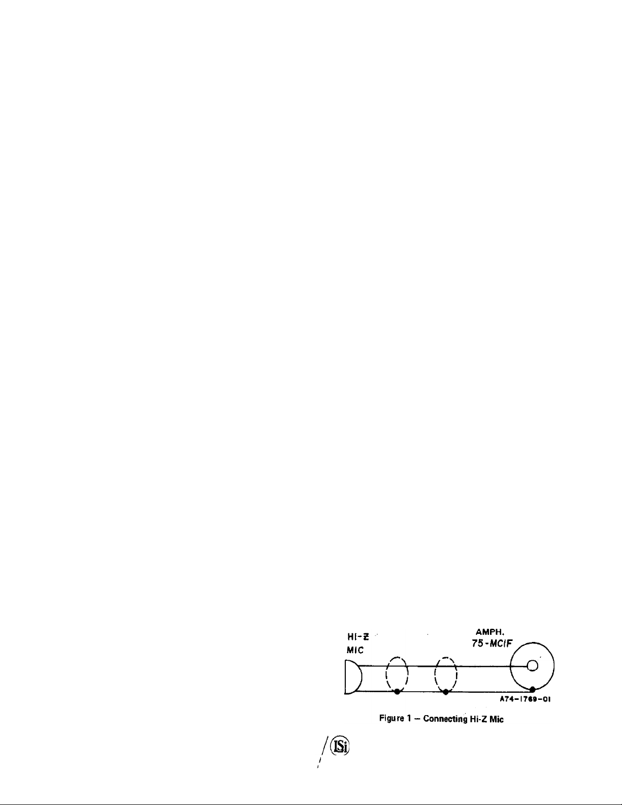
MICROPHONE: Connect the microphone to the MIC
receptacle on the rear panel.
The microphone should be of the high-impedance
ceramic, or dynamic type. Connect the microphone as
shown in figure 1. The length of the interconnecting cable
should be under 35 feet. Where longer lines are necessary, a
low impedance microphone should be used along with
Model IT-1, in-line type microphone transformer.
MICROPHONE PRECEDENCE: Microphone precedence
may be accomplished by connecting the circuit shown in
PRINTED IN U5.A.
6-76
LEAH StEGLER, INC.
BOGEN DIVISION
/ Ю. aoxsm
/ PAKAUUS.N. J.t7IS2
54-5615-05
Page 2
HI z
MItPOPHOHE
fSHURE 4aO OR
for 70V OPERATION
FOR 25 V OPERATION
OR SELECTED IMPEDANCES
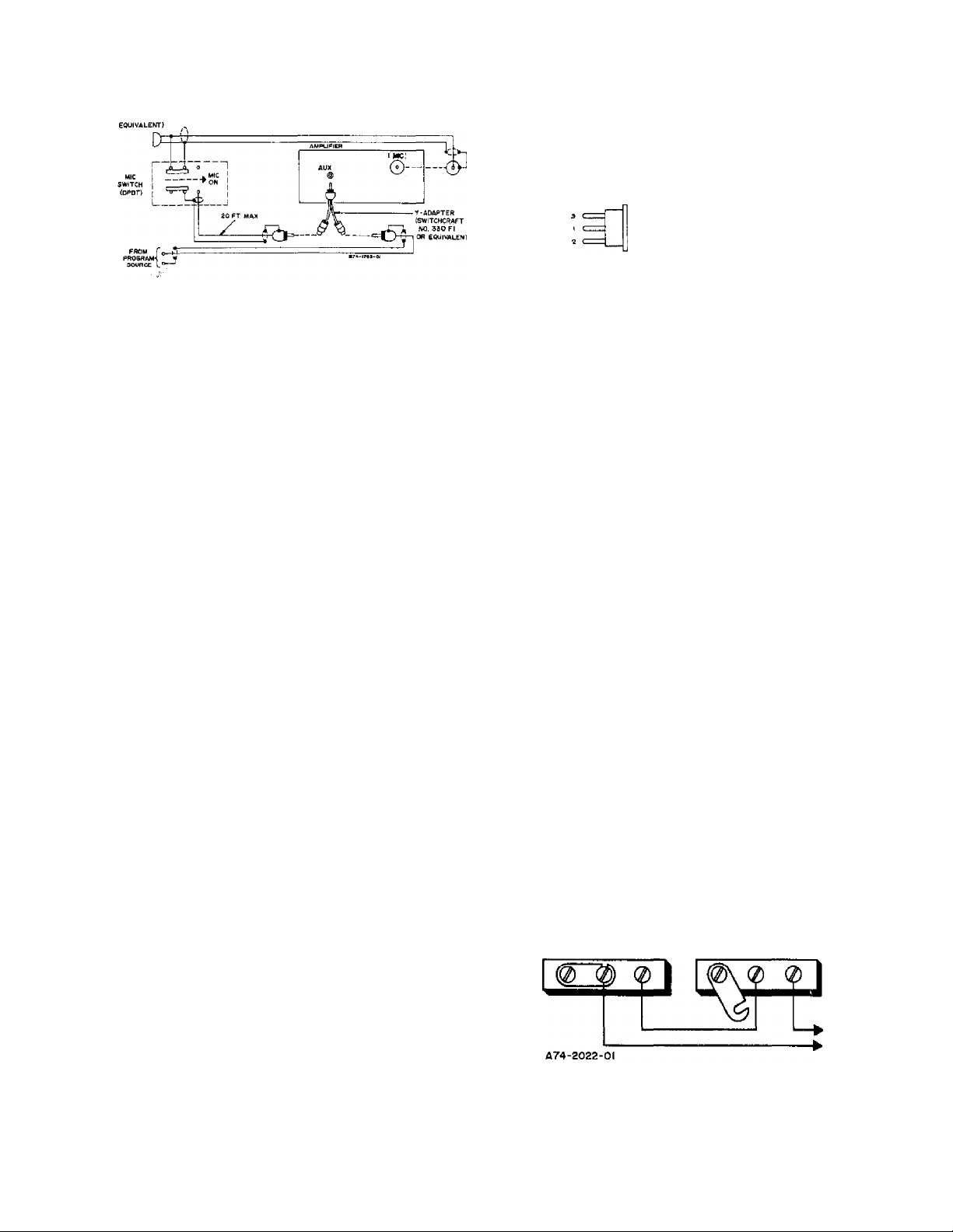
Figure 2 — Microphone Precedence Circuit
figure 2. The equipment consists of a microphone, a
Y-adapter (Switchcraft Part No. 330F1), a single-conductor
shielded cable (20 feet maximum length) and a SPOT
switch. If the microphone switch has an extra set of contacts
for controlling an external circuit, such as on the Shure
Model 450, the SPOT switch is not required.
Plug the Y-adapter into the AUX input jack on the rear
of the amplifier. Connect the program source and precedence
switch to the Y-adapter, as shown in the figure. Connect
the microphone input to the MIC input jack.
PHONO; Connect a phonograph (with ceramic cartridge) to
the AUX jack, using a single-conductor shielded cable
terminated in a standard RCA phono plug. It is recom
mended that a separate ground wire be connected between
the phono player base and the amplifier GND terminal to
minimize hum pick-up.
TUNER, TAPE, ETC.: The AUX input may be used for
souices other than a phonograph. Any signal soprcc having
a highdevel (.15-3V) output may be connected to these
inputs. This includes such Bogen equipment as the Model
BRC 3-speed automatic record changer, and Model TP160
AM/FM tuner.
OUTPUT CONNECTIONS
Figure 3 — Speaker Output Plug Wiring
When the speaker socket is used, connect the wired plug
to the socket. Attach the impedance selector lead to the
output terminal which corresponds to the speaker system
impedance. For 70-volt operation, it is only necessary to
connect the wired plug to the quick-disconnect speaker
socket, leaving the impedance selector discormected. Note
that the arrangement in figured is for unbalanced speaker
lines, with the link between COM and GND closed. For
balanced lines, open the link between COM and GND.
NOTE
For balanced output lines, remove the link
between COM and GND output terminals. If
the line is shielded, connect the shield to GND.
CONNECTING AMPLIFIERS IN SERIES
Pairs of Bogen CIO amplifiers can be connected in series
to effectively double the power output into the same
speaker system. See figure 4 for connection diagram. Be
certain to remove the link between COM and GND of
amplifier No. 2. Note that this arrangement is for
unbalanced speaker lines. For balanced lines also remove
the link between COM and GND of amplifier No. 1.
( ^
SPEAKERS: The amplifier may be uspd with speaker
systems rnteri at 4, S and 16 ohms and with 25-volt and
70-volt constant voltage^systems. For detailed information
on the installation of multiple speaker systems, refer to the
Speaker Installation Bulletin (no. 54-5001) included.
In permanent installations, where speakers will remain
connected to the amplifier, connect the speaker system
directly to the Speaker Output terminals on the rear of the
amplifier. Connect one speaker lead to the COM terminal
and the other to the terminal corresponding to the im
pedance of the speaker system.
CAUTION
To minimize shock hazard. Class 1 wiring as
defined in local building codes should be used
for 70-volt outputs. All other outputs may use
Class 2 wiring.
The input cabling must be arranged to parallel the inputs
of the two amplifiers, and the volume and tone controls of
both amplifiers must be at the same setting to assure that
each amplifier will share the load equally.
AMPLIFIER I
GND COM 1641
Figure 4 — Connecting Amplifiers in Series
-2-
AMPLIFIER 2
GND COM 1641
25V
20 W
Page 3

OPERATION
MAINTENANCE
POWER: The POWER switch on the front panel turns the
amplifier ON or OFF.
MIC: The MiC control on the front panel is used to adjust
the volume of the microphone input. Rotate the control
clockwise (to the higher numbers) to increase volume. Set
the cnntrnl to the minimum position (0) when the
microphone input is not used.
AUX: The AUX control adjusts the volume of the auxiliary
input.
TREBLE: Use the TREBLE control to adjust the tonal
balance of the amplifier output. The maximum clockwise
position provides flat frequency response and counter
clockwise produces high frequency attenuation. This
control can also be used to remove high-frequency noise
(such as record scratch) by rotating it in the counter
clockwise direction.
ACCESSORIES
WMT-1 LINE MATCHING TRANSFORMER: The Bogen
WMT-J line-matching transformer provides an impedance
match between the amplifier and a 0 level, 500/600-ohm
line. This may be a telephone line connected to the
switchboard for internal paging or used with a wired music
system. No soldering is required to connect the WMT-1 to
the amplifier.
To connect the input from a balanced 500/600-ohm
telephone line, mount the WMT-1 on the rear panel of the
amplifier, using the holes indicated on the rear panel.
Connect the input line to the three-sciew terminal board on
the WMT-1, Connect the phono plug on the WMT-I cable
to the AUX jack on the rear of the amplifier. If this jack is
being used for other sound inputs, the WMT-1 may be
connected to the MIC input. In order to do this, the WMT-1
wiring must be modified as described in the instruction
sheet supplied with the WMT-1,
MODEL BRC RECORD CHANGER: This accessory is a
3-speed ac operated record player and automatic record
changer. A tone arm housing a dual-stylus flip-over
cartridge for standard or LP records is furnished with the
unit.
RPK-35 RACK PANEL: The Bogen Model RPK-35 rack
panel is designed to mount the amplifier in a standard
19-inch sound rack. The rack panel is finished in gray
enamel.
WMK-1 IN-WALL MOUNTING KIT: The Bogen Model
WMK-1 In-Wall Mounting Kit is designed to mount the
amplifier flush in a wall. Depth of the mounted unit is 3V4
inches.
IT-1 IN-LINE MICROPHONE TRANSFORMER: The IT-1
features full frequency response 20 - 20,000 Hz, mag
netically shielded, matches 150 - 250 ohm microphones to
Hi-Z inputs. The input connector is Cannon XLR-3-12 and
the output connector is Switchcraft 250-1F,
CAUTION
There are no user replaceable parts within the
unit. Have all internal servicing done by a
qualified technician.
BOGEN SERVICE
We are interested in your Bogen equipment for as long as
you have it. If trouble ever develops, do not hestitate to ask
our advice or assistance. Information can be obtained by
writing to Service Department, Bogen Division, P.O. Box
500, Paramus, N.J. 07552.
When communicating with us, give the model and scries
designation of your unit. Describe the difficulty and
include details on the electrical connections to associated
equipment, and list such equipment. When we receive this
information, we Will send you service information if the
trouble appears to be simple. If the trouble requires
servicing, we shall send you the name and address of the
nearest Bogen authorized service agency to which you can
send your unit for repairs.
When shipping your unit, pack the amplifier well, using
the original shipping carton, or a similar container and filler
niatedal, to prevent damage In transit. Send the unit, fully
insured and prepaid, via railway express. Do not ship via
parcel post unless so instructed. The unit will be promptly
repaired and returned to you express prepaid.
OVER LOAD PROTECTION
The amplifier output is protected against overload and
shorted speaker lines by a thermostat enclosed in the
power transformer. If the breaker opens, the amplifier will
have no output. Set the ac power switch to off and wait a
reasonable time for the breaker to reset. Return the ac
power switch to on. If the breaker trips again, do not
attempt to reset it but have the trouble investigated by a
qualified technician.
REPLACING TRANSISTORS
When replacing the output transistors, clean all foreign
matter from the heat sink, insulator, and transistor. Brush a
generous amount of silicon compound such as Dow Corning
No. 340 to completely cover both surfaces of the insulator
(Part No. 16-9278-01). Place the insulator between the heat
sink and the replacement transistor. Use the original
transistor mounting hardware to mount the replacement
transis Lur.
CAUTION
All transistors are soldered to ensure maximum
reliability. When soldering leads, use a heat sink
(such as a small alligator clip) between the
transistor and the source of heat.
-3-
Page 4

REPLACEMENT PARTS
Ref. No. Part No.
Description
Most components are standard parts available through
reputable parts jobbers. The parts listed here may be
obtained from Bogen distributors, service agencies or
directly from the factory. When ordering a part, specify a
part number and description of the part as listed. Specify
the model of the unit and give the series designation, which
is a letter followed by numbers, printed on the chassis. For
parts on circuit boards, also give the component board
assembly number, which begins with “45.”
When replacing transistors, use those made by the
specified manufacturers. Transistors from other suppliers
may not be satisfactory. Certain resistors must be
Allen-Bradley. These are designated by “AB” on the
schematic diagram.
Ref. No. Part No.
A1 - COMPONENT BOARD ASSEMBLY
PART NO. 45-9915-01
Desaiption
CIO 79-112-006 Capacitor, Electrolytic,
lOOOpF,55V
Cll 79-008-058 Capacitor, Electrolytic,
lOpF, 50V
C12 79-008-064 Capacitor, Electrolytic,
330pF,50V
C16,C17 79-008-062 Capacitor, Electrolytic,
100mF,50V
C21 79-112-004 Capacitor, Electrolytic,
500hF,40V
CR1,CR2
CR3
CR4
Q1
Q2
Q3. Q5
Q4
R4
Rll
R12
R30
QIOI
Q102
SWlOl
TlOl
T102
96-5193-01
96-5202-01
96-5333-01
Diode, 200 PIV, 2A
Diode, HVR3
Diode. 400 PIV, lA
96-5213-01 Transistor, 2N5089 (Motorola) or
96-5314-01
Transistor, BC149C (Siemens) or
96-5335-01 Transistor, TPl 09C (Sprague) or
96-3346-01
96-5298-01
96-5283-01
96-5290-01
77-001-712
77-001-711
Transistor, BC239C (Siemens)
Transistor, SPS-I910 (Motorola)
Transistor, MPS A55 Motorola)
Transistor, MPS A05 (Motorola)
Control, AUX Volume, 2 Meg.
Control,MIC Volume, AUX Vol
ume, 1 Meg,
77 001 731
Control, TREBLE, 1 Mog.
76-113-099 Resistor, 0.27 ohm, 5W
Chassis Electrical Parts
96-5232-03 Transistor
81-003-060 Switch, Power
83-772-000 Transformer, Power (with 110-
degree thermostat enclosed in
transformer)
83-434-000 Transformer, Output
Front f^nel Parts
03-0651-01 Knob
-4-
 Loading...