

Page 1
Page 2
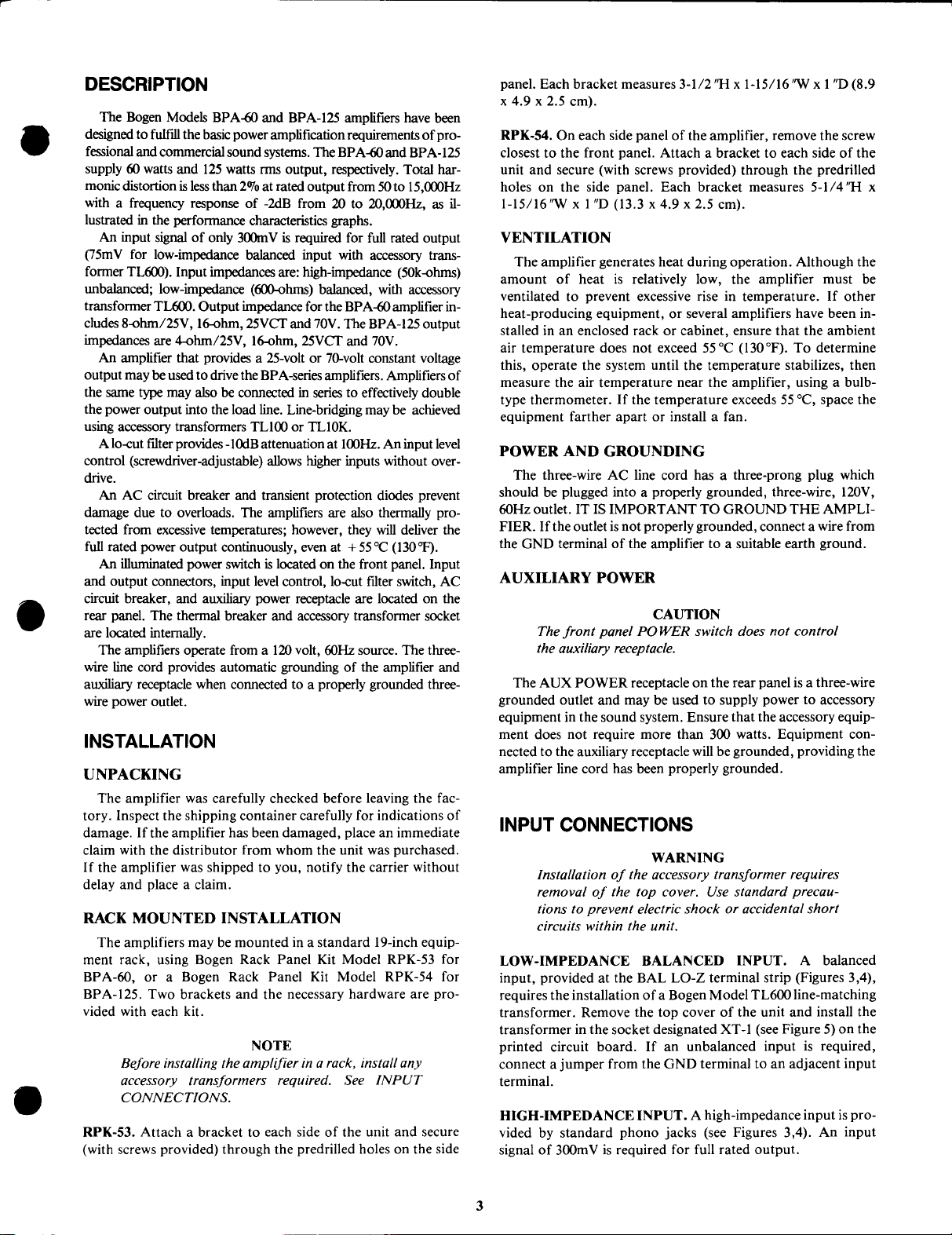
TECHNICAL SPECIFICATIONS
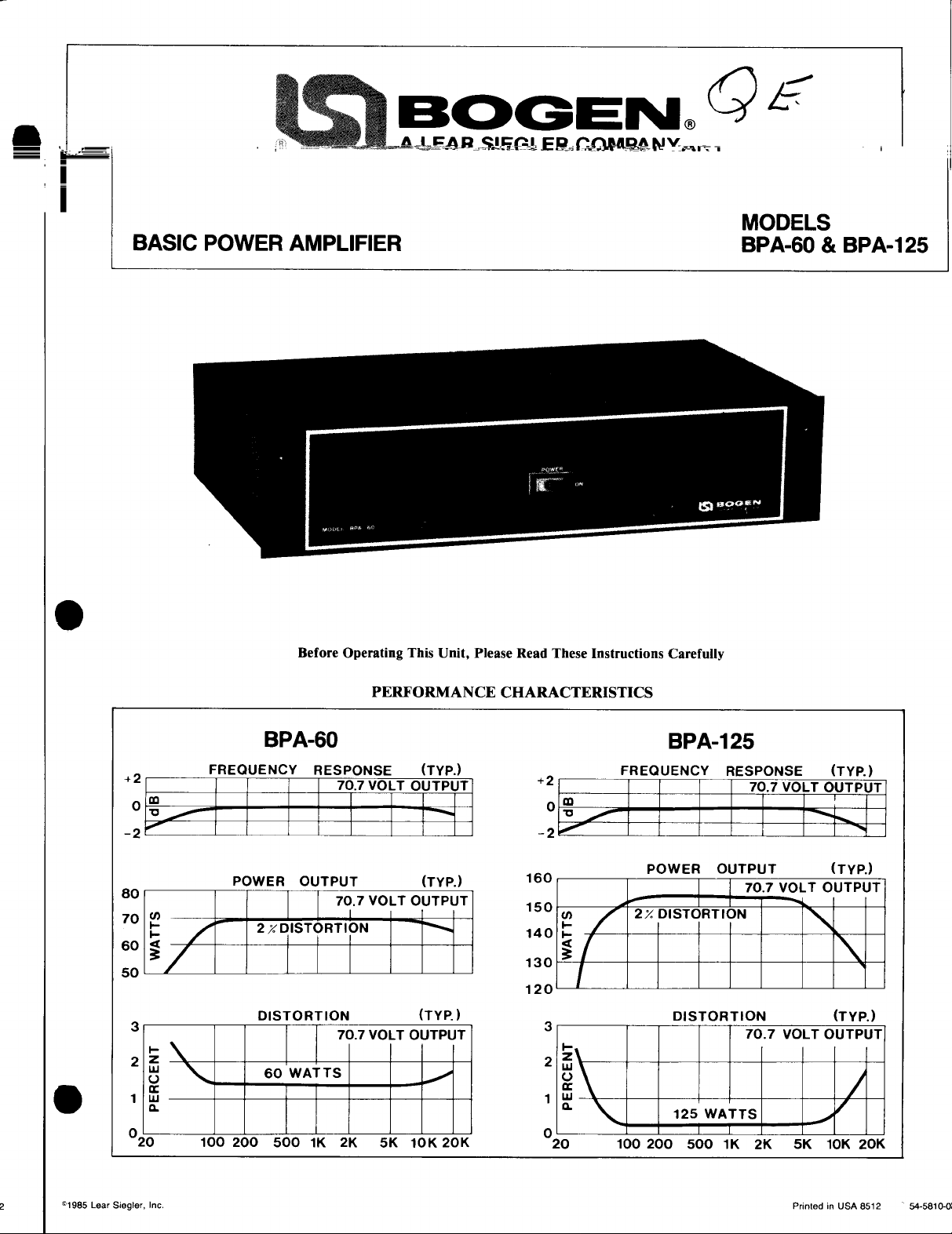
Model BPA-60
Rated Output Power:
60
watts (rms) from
I5kHz
at less than 2%THD
into rated load
Frequency Response:
Input Sensitivity:
Low-impedance, balanced: 75mV with accessory transformer Model
Output Regulation:
Hum and Noise:
Inputs (Impedance):
Low-impedance:
Line-bridging with accessory transformers
Output Loads:
Lo-Cut Filter:
Controls, Indicators;
Front Panel:
Rear Panel:
Power Consumption;
I20VAC, 60Hz
@
Full Rated Output:
Overload Protection:
Auxiliary Receptacle:
(not switched)
Dimensions:
Finish:
Weight:
Rack Panel Brackets:
Accessories:
I
I
8-ohm/25V,
25VCT and 70V
Input Level Control; Circuit Breaker Reset Switch; Lo-Cut Filter Switch
AC Circuit Breaker. Thermal Circuit Breaker, Transient Protection Diodes
15.25”Wx8”Dx3.5”H
(38.7 x 20.3 x 8.9 cm)
19
Model BPA- 125
50Hz
to
impedances
-2dB
from
20Hz
125 watts
15kHz
to 2OkHz
(rms)
from
at less than 2% THD
into rated load impedances
High-impedance: 300mV;
Better than 2dB from no load to full load
85dB below rated output
High-impedance:
600-ohms
balanced, with accessory transformer
16-ohms,
50k-ohms
unbalanced;
TLl00
4-ohm/25V,
or TLlOK
16-ohms,
25VCT and 70V
-1OdB @ 1OOHz
(Switch-Selectable)
Illuminated Power Switch
18OW
1
360w
Three-wire grounded* 300 watts maximum
15.25”Wx8”Dx5.25”H
lbs. (8.6 kg)
RPK-53
Model
TL600, 600-ohm
Model
Model TLlOK,
Black
line-matching transformer
TLIOO, 1:1
10,000-ohm
ratio transformer
line-matching transformer
(38.7 x 20.3
x
13.3 cm)
27 Ibs. (12.3 kg)
RPK-54
5OHz
TL600
TL600;
to
1
*This receptacle will be grounded only if the power amplifier has been grounded properly
All specifications subject to change without notice
AMPLIFIER
GND
AMPLIFIER I AMPLIFIER 2
GND COM
A74-2021-01
Figure 1 - Connecting Amplifiers in Series
1
COM 25VCT
l6fi
I
AMPLIFIER 2
GND COM
GND COM
25VCT
lGfI
OUTPUT
TERMINAL
sz&RoF
AMPLIFIER
7OV
AT
AT 25V RI =
RI =
Figure 2
2
10K, 1/2W
3.3K, 1/2W
-
Input From Another Amplifier
-0730-A
IMPEDANCE
INPUT
OF
POWER
AMPLIFIER
Page 3
Page 4

Figure 3 - BPA-60 Rear Panel Connection Diagram
CONNECTING AMPLIFIERS IN SERIES. Pairs of the same
amplifier model may be connected in series to effectively double the power output into the same load line (see Figure 1). Be
certain to remove the link between COM and GND terminals
on amplifier No. 2.
BRIDGING INPUT. The inputs of two or more amplifiers may
be paralleled by installing accessory transformer
to 6 amplifiers) or TLlOK (for more than 6 amplifiers) in the
transformer socket designated XT-l (see Figure 5) on the
printed circuit board. Connect the signal source to the BAL
LO-Z terminal strip and connect the cable shield to the GND
terminal. For an unbalanced input, connect a jumper wire from
the GND terminal to an adjacent input terminal.
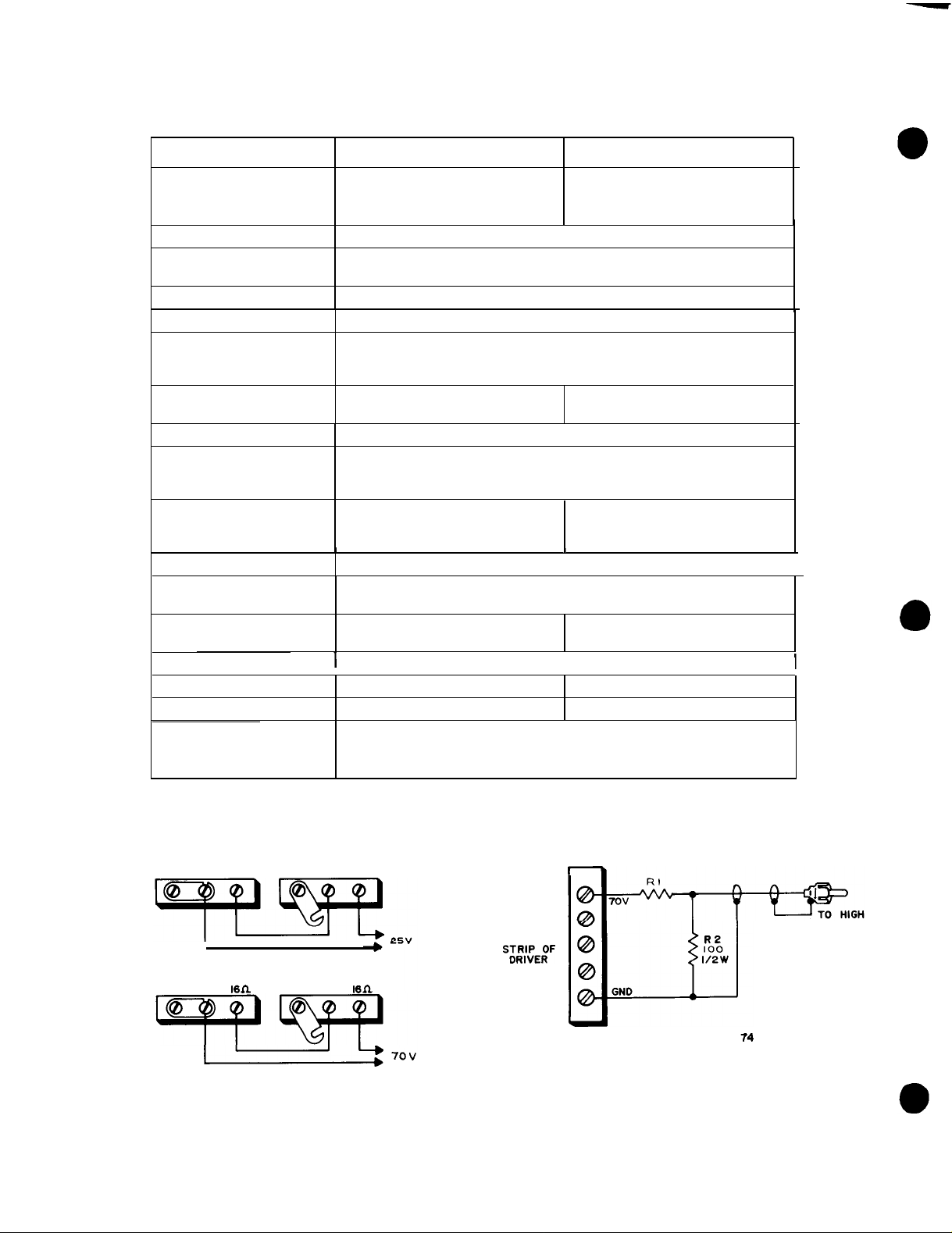
INPUT FROM ANOTHER AMPLIFIER. The BPA-60 and
BPA-125 amplifiers may be driven from an amplifier that provides a
25-volt
or 70-volt constant voltage output. Connect the
output of the driver amplifier to one of the HI-Z input jacks via
a resistor network (see Figure 2). These resistors are in addition
to the normal loudspeaker load impedance on the output of the
driver amplifier.
TLlOO
(for up
OUTPUT CONNECTIONS
Connect speaker systems directly to the output terminal strip on
the rear panel. Connect one speaker lead to the COM terminal and
the other to the terminal corresponding to the impedance of the
speaker system. If the load impedance falls between two output terminal values, use the terminal of lower impedance. Total power
distribution to the speakers should not be greater than the power
rating of the amplifier. For balanced output lines, remove the link
between the COM and GND terminals. If the line is shielded, connect the shield to the GND terminal. For unbalanced speaker lines,
close the link between the COM and GND terminals.
HUM. If the connections between the signal sources and amplifier
are incorrect or defective, hum-type interference may occur. Check
for proper grounding, broken wires, shields, poor connector contacts, etc. Keep input cables away from speaker cables and speaker
cables away from AC power lines. Where a turntable or other auxiliary equipment is used, it may be necessary to connect a separate
ground wire from the chassis of such equipment to a suitable earth
ground.
POWER. The POWER switch applies power to the amplifier; it
does not control any associated equipment which may be connected
to the auxiliary power receptacle on the rear panel. The switch lamp
will illuminate when power has been applied to the unit.
CAUTION
Follow
local electrical codes
when connecting ampljier
output.
Fires 3 and 4 show the location and impedance values for the
output terminal strip. Class 2 wiring is acceptable for output loads.
SPEAKERS. The amplifier may be used with most conventional
speaker systems. For detailed information on the installation of
multiple speaker systems, refer to the Speaker Installation Bulletin
(No.
54-5001)
included with this unit.
LO-CUT FILTER SWITCH. The LO-CUT filter switch, located on
the rear panel, provides
INPUT LEVEL CONTROL.
on the rear panel, adjusts the input signal applied to the amplifier.
Turn the adjustable screw clockwise to increase the level.
Many
loudspeakers
-1OdB
attenuation at
The INPUT LEVEL control, located
CAUTION
may be damaged if
100Hz.
overdriven.
Therefore, always begin system setup with the input
level control fully
counterclockwise
and gradually in-
crease the setting to obtain the desired output level.
4
Page 5

Figure 4 - BPA-125 Rear Panel Connection Diagram
THERMAL BREAKER.
no audio output; however, the power switch lamp will remain illuminated. Wait approximately two minutes for the breaker to reset. If
it resets and then opens again, investigate the cause of the
temperature overload. This may be due to improper connections at
the output terminals or to excessive environmental heat with inadequate ventilation. The thermal breaker will open when the
temperature at the output transistor heat sink reaches 105 °C.
CIRCUlT BREAKER..
switch lamp
however, there will be power at the AUX POWER receptacle on the
rear panel. Set the POWER switch to OFF and momentarily depress
the red button on the circuit breaker to reset it. Return the POWER
switch to ON. If the circuit breaker trips again, do not attempt to
reset it; have the trouble investigated by a qualified technician.
wiIl
go out and the amplifier will have no output;
If the thermal breaker opens, there will be
If the AC circuit breaker opens, the power
MAINTENANCE
CAUTION
There are no user-serviceable parts within the
amplifier.
qualifed technician. The warranty will become void if
repairs are made by other than the
Department or authorized service agency.
BOGEN
Our Service Department is interested in the maintenance of
your
Bogen equipment. If trouble ever develops, do not hesitate
to ask our advice or assistance. Information may be obtained by
writing to: Service Department, Bogen Division, P.O. Box 500,
Paramus, N.J. 07653.
Have all internal servicing performed by a
Bogen
SERVICE
Service
When communicating with us, give the model and series
designation of your unit. Describe the difficulty and include
details on the electrical connections to associated equipment,
such as preamplifiers, speakers, etc. We will send you service information if the trouble appears simple. If the amplifier requires
servicing, we will send you the name and address of the nearest
authorized Bogen service agency.
When shipping the amplifier, pack it well, using the original
shipping carton or similar container and filler material to prevent
damage in transit.
printed circuit board beforeshipping.
and freight prepaid via UPS or other responsible carrier. The
repaired unit may be picked up by you personally or will be
returned to you freight prepaid while in warranty.
Remove any plug-in transformer from the
Send the unit, fully insured
REPLACING COMPONENTS
All semiconductor components on the printed circuit board
are soldered in place to ensure maximum reliability. When
soldering or unsoldering transistors and diodes, use a heat sink
(such as a small alligator clip) between the source of heat and the
component. When replacing driver and output transistors, be
certain to install the case/heat sink insulator, after lightly coating
both sides with a thermal conducting compound (such as Dow
Corning No. 340, or equivalent).
REPLACEMENT PARTS
Most components used in the amplifier are standard parts
available through reputable parts suppliers. The parts listed here
may be obtained through Bogen distributors, service agencies or
directly from the factory. When ordering a part, specify the part
number and the description, as listed. Specify the model of the
unit and give the series designation, which is a letter followed by
numbers, located on the rear panel. For parts on the circuit
board, also give the component board assembly number, which
begins with “45”.
Page 6

TRANS. SKT. XT1
0
I
PARTS LIST
Designation
c2
C3,4
C6
CR1-4
:;
;:
Rl
R3
R4
R5
Rl8,19
Sl
-
Cl01
Cl03
Cl04
C201
C202
Part
Number
45-7241-05
79-l 19-001
79-008-065
79-008-062
96-5333-01
96-5643-01
96-5365-01
96-5459-01
96-5458-01
77-001-818
75-154-124
75-154-154
75-154-334
76-
107-096
81-003-067
70-9302-01
78-200-l 16
79-
118-002
79-118-004
79-118-006
79-509-056
Figure 5 -
Description
PC Board
Ptd. Cir. Bd. Assy.
Cap., Elect., 470
Cap., Elect., 10
Cap., Elect., 100
Diode,
Transistor, KTC2240
Transistor,
Transistor,
Transistor,
Control, Scr. Adj., 100 kilohm
Resistor, 120 kilohm, ¼W, 1%
Resistor, 150 kilohm,
Resistor, 330 kilohm,
Resistor,
Switch, Slide, Miniature
Clip, Heat Sink (2)
Chassis
Cap., Cer. Disc, 0.01
Cap., Elect., 13,000
Cap., Elect., 8800
Cap., Elect., 5000
Cap., Elect., 6000
4OOprv @ 1A
.82
(BPA-125)
(BPA-125)
(BPA-60)
(BPA-60)
MPSA56
2N6292
2N6107
ohm, 2W
BPA-60/BPA-125
µF,
63V
µF,
63V
µF,
50V
1/4W,
1/4W,
µF,
1400V
µF,
40V
µF,
75V
µF,
50V
µF,
75V
1%
1%
Printed Circuit Board
Schematic
Designation
CBlOl
CB102
CB201
CR101
CR201 -204
QlOl
4102,103
Q104-107
R101,102
R103-106
R107
R109
R201,203
R202
SW101
TlOl
T102
T201
T202
-
Part
Number
94-0023-10
94-0014-07
94-0023-05
96-5373-01
96-5241-01
96-5213-01
96-5385-01
96-5385-01
76-114-107
76-l 14-102
75-154-182
75-742-101
76-l 14-102
75-154-132
81-009-036
83-831-000
83-492-000
83-814-000
83-491-000
14-9088-01
Description
Breaker, Circuit,
(BPA-125)
Thermostat
Breaker, Circuit, 1.6A (BPA-60)
Rectifier, Bridge (BPA-125)
Diode, 300prv
Transistor,
Transistor, 2N3055H, RCA
Transistor, 2N3055H, RCA
(BPA-125)
Resistor, 3.3 ohm, 5W
(BPA-125)
Resistor, 0.27 ohm, 5W
(BPA-125)
Resistor, 1800 ohm,
(BPA-125)
Resistor, 100 ohm, 7W
Resistor, 0.27 ohm, 5W
(BPA-60)
Resistor, 1300 ohm,
(BPA-60)
Switch, Power
Transformer, Power (BPA-125)
Transformer, Output (BPA-125)
Transformer, Power (BPA-60)
Transformer, Output (BPA-60)
Foot, Rubber
4.OA
@
3A (BPA-60)
2N5089
1/4W,
1/4W,
1%
1%
6
Page 7

 Loading...