

Page 1
© 2013 Bogen Communications, Inc.
All rights reserved.
Specifications subject to change without notice.
54-2218-01B 1308
Bogen Pro
BP15DSP & BP12DSP
Powered Loudspeakers
Installation and Use Manual
Page 2
NOTICE: Every effort was made to ensure that the information in this guide was complete
and accurate at the time of printing. However, information is subject to change.
WARNING: To reduce the risk of Fire or Electric Shock, Do Not Expose this apparatusto
rain or moisture. Apparatus shall not be exposed to dripping or splashing and no objects
filled with liquids, such as vases shall be placed on the apparatus.
WARNING: Only connect unit to AC mains outlet providing protective earthing connection.
NOTE: Mains plug or an appliance coupler are used as disconnect devices from the main
and shall remain readily accessible and operable.
CAUTION: These servicing instructions are for use by qualified service personnel only.
To reduce the risk of electric shock, do not perform any servicing other than that contained
in the operating instructions unless you are qualified to do so.
Always follow these basic safety precautions when installing and using the unit:
IMPORTANT SAFETY INSTRUCTIONS
1. Read these instructions.
2. Keep these instructions.
3. Heed all warnings.
4. Follow all instructions.
5. Do not use this apparatus near water.
6. Clean unit with dry cloth.
7. Do not block any ventilation openings. Install in accordance with the manufacturer's
instructions.
8.
Do not install near any heat sources such as radiators, heat registers, stoves, or other
apparatus
(including amplifiers) that produce heat.
9. Do not defeat the safety purpose of the polarized or grounding-type plug. A polarized
plug has two blades with one wider than the other. A grounding-type plug has two blades
and a third
grounding prong. The wide blade, or the third prong, are provided for your
safety. If the provided
plug does not fit into your outlet, consult an electrician for replace-
ment of the obsolete outlet.
10. Protect the power cord from being walked on or pinched particularly at plugs, convenience receptacles, and the point where they exit from the apparatus.
11. Only use attachments/accessories specified by the manufacturer.
12. Unplug this apparatus during lightning storms or when not used for long periods of time.
13. Refer all servicing to qualified service personnel. Servicing is required when the apparatus has been damaged in any way, such as power-supply cord or plug is damaged,
liquid has been spilled or objects have fallen into the apparatus, the apparatus has been
exposed to rain or moisture, does not operate normally, or has been dropped.
CAUTION
RISK OF ELECTRIC SHOCK DO NOT OPEN
CAUTION: TO PREVENT THE RISK OF ELECTRIC SHOCK, DO NOT REMOVE
ANY FRONT/BACK COVERS OR PANELS. NO USER-SERVICEABLE PARTS
INSIDE.
REFER SERVICING TO QUALIFIED PERSONNEL.
The exclamation point within an equilateral triangle is intended to
alert the user to the presence of important operating and maintenance (servicing) instructions.
The lightning flash with arrowhead symbol, within an equilateral
triangle, is intended to alert the user to the presence of uninsulated
"dangerous voltage" within the product's enclosure that may be of
sufficient magnitude to constitute a risk of electric shock to persons.
CAUTION
DANGER OF EXPLOSION IF
TRANSMITTER BATTERY IS
INCORRECTLY REPLACED.
REPLACE ONLY WITH SAME
OR EQUIVALENT TYPE
WARNING
BATTERY SHALL NOT BE
EXPOSED TO EXCESSIVE
HEAT SUCH AS SUNSHINE,
FIRE, OR THE LIKE.
Page 3
1
Introduction
Quick Start
Your Bogen Pro BP15DSP/BP12DSP Powered Loudspeaker is capable of high
sound pressure levels and has been designed to give you performance that is better
than any loudspeaker in this range, thanks to the quality of its transducers and built-in
amplifier. Enjoy your new Bogen Pro Powered Loudspeaker. Please be sure to read
and follow instructions within this manual carefully before you begin operation.
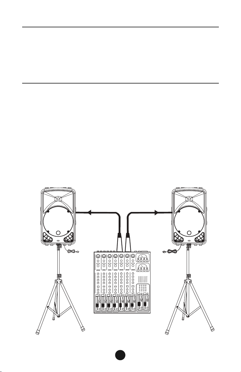
Make all initial connections with all equipment powered off, and ensure that all the
main volume controls are turned down completely.
1. Connect one end of the signal cable at your audio mixerʼs main output.
Then connect the other end of the signal cable into the LINE input of your
powered speaker cabinet. Repeat for second speaker.
2. Connect the power cord(s) to AC Mains.
3. Turn on your mixer first, then the powered speaker cabinet(s).
4. Set switch to “LINE” position and turn up the volume control of the powered
speaker cabinet(s).
5. Use mixerʼs level controls to manipulate the output level accordingly.
6. After using, turn off your powered speaker cabinets first, then the mixer.
Power Cord
Tripod
Mount
Left
Main Mix
Output
Signal Cable
Mixer
Power Cord
Tripod
Mount
Right
Output
Main Mix
Signal Cable
Page 4
PIN 1
LINK
BAL
INPUT
110-120V 220-240V
POWER
ON
OFF
AC INPUT
"WARNING"
TOREDUCE THERISK OFFIRE ORELECTRIC SHOCKDO NOTEXPOSE THISPRODUCTTO RAINOR MOISTURE.
AC FUSE
110-120V T6.3AL AC250V
220-240V T3.15AL AC250V
AC INPUT
110-120V~50/60Hz
220-240V~50/60Hz
MADE IN CHINA
MODEL
SERIAL
POWER CONSUMPTION: 550W
LINE
MIC
LOW
FREQUENCY
CUT BOOST
VOLUME
0 dB
FLAT
SIGNAL
POWER
LIMIT
Useonly witha250V fuse
BP15DSP
2
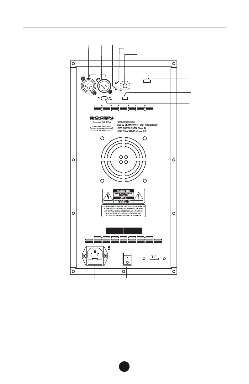
Panel Description
(1) IEC SOCKET WITH MAINS FUSE
(2) MAINS POWER SWITCH
(3) AC MAINS SELECTOR
(4) LINE/MIC INPUT ON COMBO
(XLR F/ 1/4”) CONNECTOR
(5) LINK OUT ON XLRM CONNECTOR
(6) POWER INDICATOR LED
(7) SIGNAL/CLIP INDICATOR LED
(8) MAIN VOLUME CONTROL
(9) LOW-FREQUENCY SELECTOR SWITCH:
CUT: HI-PASS FILTER
FLAT: NO EFFECT
BOOST: LOW-FREQUENCY SHELF
(10) "INPUT SENSITIVITY" SWITCH
FOR LINE OR MIC
(11) PIN 1 GROUND LIFT SWITCH
(4)
(5)
(6)
(7)
(8)
(9)
(10)
(11)
(1)
(2)
(3)
Page 5

3
Wire Connections
Tip
Ring
Sleeve
Tip
Ring
Sleeve
1
2
3
TIP RINGSLEEVE
TIP RINGSLEEVE
21
3
1
2
3
1
2
3
Tip
Ring
Sleeve
1
2
3
1
2
3
TIP RINGSLEEVE
Tip
Ring
Sleeve
Tip
Sleeve
1
2
3
1
2
3
2
1
3
Tip
Ring
Sleeve
Tip
Sleeve
1
2
3
1
2
3
Tip
Ring
Sleeve
Tip
Sleeve
1
2
3
1
2
3
1
2
3
TIP RINGSLEEVE
TIP RINGSLEEVE
TIP RINGSLEEVE
TIP RINGSLEEVE
TIP RINGSLEEVE
TIP RINGSLEEVE
For Powered Speaker Cabinets
Audio connections are mostly intended for the signal flow. Determine the wire configuration needed for your real application. Typical options are:
UNBALANCED
BALANCED
Page 6

4
LINE IN
LINE IN
MAIN OUT
AUX OUT
CAM8PRO MIXER
Power
Ratio
0 100
AUX
0+3 +12+6
+20
-20
MAIN
-12-18 -6 -3
Threshold
On
8
Cut
Low
Off
-
+
M.A
BUS
Low
Cut
7
Limit
Headphone
-+-
+
Low
Cut
6
BUS
M.A
-
+
5
M.A
BUSCut
Low
Cut
Low
+
-
4
M.A
BUS
Low
Cut
3
-
+
Low
Cut BUS
M.A
2
-+-
+
Cut
Low
1
M.A
BUS
BUS
M.A
BUS
M.A
CAM8PRO
Two Speakers in Stereo Operation
Input Sensitivity = “LINE”
Hook-Up Diagrams
Single Speaker with Direct Microphone
Input Sensitivity = “MIC”; Low Frequency = “CUT”
MIC IN
Page 7

5
Hook-Up Diagrams
LINK TO NEXT SPEAKER
LINK
LINE IN
LINE IN
SHIELD
LINK
BAL
INPUT
110-120V 220-240V
POWER
ON
OFF
ACINPUT
MODEL
SERIAL
LINE
MIC
FLAT
MONITOR LOUDNESS
VOLUME
MAX
EQPRESETS
SIGNAL
POWER
LIMIT
BAL OUT
VMIX MIXER / PRE-AMPLIFIER
LINK
LINE IN
SHIELD
LINK
BAL
INPUT
110-120V 220-240V
POWER
ON
OFF
ACINPUT
MODEL SERIAL
LINE
MIC
FLAT
MONITOR LOUDNESS
VOLUME
MAX
EQPRESETS
SIGNAL
POWER
LIMIT
SHIELD
LINK
BAL
INPUT
110-120V 220-240V
POWER
ON
OFF
ACINPUT
MODEL
SERIAL
LINE
MIC
FLAT
MONITOR LOUDNESS
VOLUME
MAX
EQPRESETS
SIGNAL
POWER
LIMIT
SHIELD
LINK
BAL
INPUT
110-120V 220-240V
POWER
ON
OFF
ACINPUT
MODEL SERIAL
LINE
MIC
FLAT
MONITOR LOUDNESS
VOLUME
MAX
EQPRESETS
SIGNAL
POWER
LIMIT
LINK
LINE IN
Multiple Speakers with the same Source
Input Sensitivity = “LINE”
Page 8
6
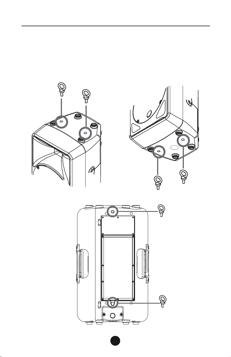
Multi-Use Cabinet
The BP15DSP/BP12DSP Loudspeaker cabinet provides suspension
points for flown installation (M10 x1.5PH, LENGTH:30mm).
For further details, please refer to the illustration below.
(Rigging accessory to
be appropriate forged
type, not supplied.)
6 Suspension Points for Rigging
with Forged Eyebolts
TOP:
2 Rigging
Points
BOTTOM:
2 Rigging
Points
REAR:
2 Rigging
Points
Page 9
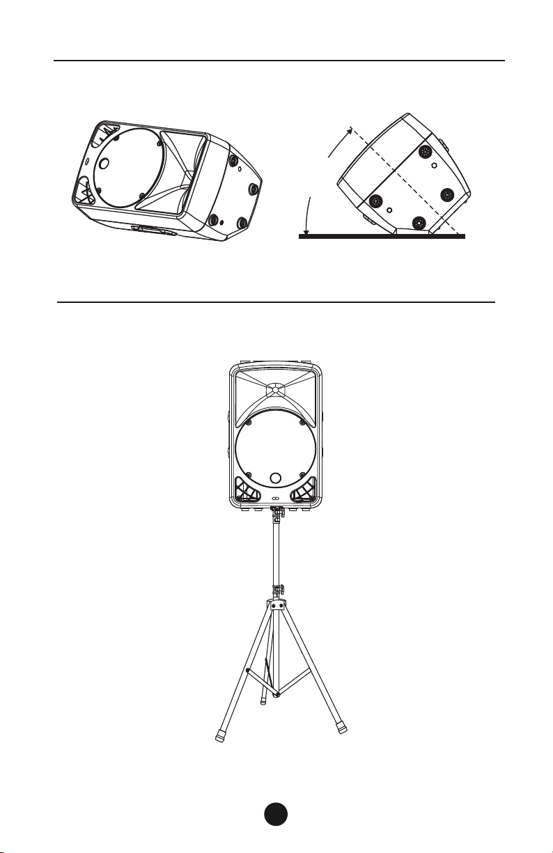
Multi-Use Cabinet
BP15DSP/BP12DSP provides 45oangle when used
on floor as a stage monitor.
45
o
BP15DSP/BP12DSP provides a Tripod Mount located in bottom
of the speaker for raised use on tripods.
(Tripod assembly
sold separately)
4
7
NOTE: When used as a stage monitor (or with a subwoofer), Low-Frequency
switch should be set to “CUT”.
NOTE: When used on a tripod (to compensate for “Free-Field”),
Low-Frequency switch should be set to “BOOST”.
Page 10

Technical Specifications
BP15DSP Loudspeaker
System Type......................................2-Way Powered Speaker
Transducer Low ................................15" Neodymium Woofer, 2.5" Voice Coil
Transducer High................................1" Compression Driver, 1.75" Voice Coil
Horn Coverage (H˚x V˚) ..................90˚H x 45˚V
Frequency Response ......................45 Hz to 20 kHz with FLAT
Crossover Frequency ......................2.2 kHz-DSP Processor 12 dB/oct
Max. SPL (1m)....................................124 dB Maximum
Power System ..................................Bi-Amp (Low: Class D 300W High; Class AB 50W), RMS 350W
Connector ..........................................LINE/MIC Input with Combo on (XLR/1/4”) Connector
External Controls ..............................Volume Control, LINE/MIC Switch, Low Frequency Switch,
Power, Pin 1 Lift Switch
LED ....................................................Power (Green), Signal/Clip (Green/Red)
Low Frequency Presets ..................CUT - FLAT - BOOST
Electronic Protections......................Thermal / Overload / Digital Limiter / Compressor
Power Supply ....................................110-120V~50/60 Hz or 220-240V~50/60 Hz Switchable (550W)
Enclosure Construction ..................Plastic Cabinet, Trapezoidal & Monitor Shape, Metal Grille,
Rubber Feet, 2 Handles (both sides)
Mounting ............................................36mm standard pole-mount, M10 6PCS Flying Points
Dimensions (H x W x D) ..................26-1/8" x 15-1/2" x 15-7/8" (664mm x 396mm x 402mm)
Net Weight ........................................40.5 lbs. (18.4kg)
BP12DSP Loudspeaker
System Type......................................2-Way Powered Speaker
Transducer Low ................................12" Neodymium Woofer, 2.5" Voice Call
Transducer High................................1" Compression Driver, 1.75" Voice Call
Horn Coverage (H˚x V˚) ..................90˚H x 45˚ V
Frequency Response ......................50 Hz to 20 kHz with FLAT
Crossover Frequency ......................2.4 kHz-DSP Processor 12 dB/oct
Max. SPL (1m)....................................123 dB Maximum
Power System ..................................Bi-Amp (Low: Class D 300W High; Class AB 50W), RMS 350W
Connector ..........................................LINE/MIC Input with Combo on (XLR/1/4”) Connector
External Controls ..............................Volume Control, LINE/MIC Switch, Low Frequency Switch,
Power, Pin 1 Lift Switch
LED ....................................................Power (Green), Signal/Clip (Green/Red)
Low Frequency Presets ..................CUT - FLAT - BOOST
Electronic Protections......................Thermal / Overload / Digital Limiter / Compressor
Power Supply ....................................110-120V~50/60 Hz or 220-240V~50/60 Hz Switchable (550W)
Enclosure Construction ..................Plastic Cabinet, Trapezoidal & Monitor Shape, Metal Grille,
Rubber Feet, 2 Handles (both sides)
Mounting ............................................36mm standard pole-mount, M10 6PCS Flying Points
Dimensions (H x W x D) ..................26-1/8" x 15-1/2" x 14-1/4" (664mm x 396mm x 362mm)
Net Weight ........................................38.5 lbs. (17.5kg)
8
Page 11

The Bogen Pro BP15DSP & BP12DSP Powered Loudspeakers are warranted to be
free from defects in material or workmanship for two (2) years from the date of sale to
the original purchaser. Any part of the product covered by this warranty that, with normal
installation and use, becomes defective will be repaired or replaced by Bogen, at our
option, provided the product is shipped insured and prepaid to: Bogen Factory Service
Department, 50 Spring Street, Ramsey, NJ 07446, USA. The product will be returned
to you freight prepaid. This warranty does not extend to any of our products that have
been subjected to abuse, misuse, improper storage, neglect, accident, improper installation or have been modified or repaired or altered in any manner whatsoever, or where
the serial number or date code has been removed or defaced.
THE FOREGOING LIMITED WARRANTY IS BOGEN'S SOLE AND EXCLUSIVE
WARRANTY AND THE PURCHASER'S SOLE AND EXCLUSIVE REMEDY. BOGEN
MAKES NO OTHER WARRANTIES OF ANY KIND, EITHER EXPRESS OR
IMPLIED, AND ALL IMPLIED WARRANTIES OF MERCHANTABILITY OR
FITNESS FOR A PARTICULAR PURPOSE ARE HEREBY DISCLAIMED AND
EXCLUDED TO THE MAXIMUM EXTENT ALLOWABLE BY LAW. Bogen's liability
arising out of the manufacture, sale or supplying of products or their use or disposition,
whether based upon warranty, contract, tort or otherwise, shall be limited to the price
of the product. IN NO EVENT SHALL BOGEN BE LIABLE FOR SPECIAL, INCIDEN-
TAL OR CONSEQUENTIAL DAMAGES (INCLUDING, BUT NOT LIMITED TO, LOSS
OF PROFITS, LOSS OF DATA OR LOSS OF USE DAMAGES) ARISING OUT OF
THE MANUFACTURE, SALE OR SUPPLYING OF PRODUCTS, EVEN IF BOGEN
HAS BEEN ADVISED OF THE POSSIBILITY OF SUCH DAMAGES OR LOSSES.
Some States do not allow the exclusion or limitation of incidental or consequential
damages, so the above limitation or exclusion may not apply to you. This warranty
gives you specific legal rights, and you may also have other rights which vary
from State to State.
Products that are out of warranty will also be repaired by the Bogen Factory Service
Department — same address as above or call 201-934-8500. The parts and labor
involved in these repairs are warranted for 90 days when repaired by the Bogen Factory
Service Department. All shipping charges in addition to parts and labor charges will
be at the owner's expense. All returns require a Return Authorization number.
7/22/2008
Limited Warranty; Exclusion of Certain Damages
9
Page 12

50 Spring Street, Ramsey, NJ 07446 USA
Tel. 201-934-8500 • Fax: 201-934-9832
www.bogen.com
 Loading...