

Page 1
BCBZ Series Zone Clock Installation Manual
Table of Contents
MOUNTING
Mounting Instruction……………….…………………………………………………....... Page 2
WIRING AND JUMPERS
Wiring Information and Jumper Settings……………..…………………………………... Page 3
OFFSETTING THE HOUR
Offsetting the Hour……………….……………………………………………………. …. Page 4
FREQUENTLY ASKED QUESTIONS
BCBZ Series Zone Clock Frequently Asked Questions………………………..…………… Page 5
TROUBLESHOOTING
BCBZ Series Zone Clock Troubleshooting…………….…………………………………… Page 6
FOR SYSTEM WIRING DIAGRAMS, PLEASE REFER TO SYSTEM INFORMATION
50 Spring Street, P.O. Box 575, Ramsey, New Jersey 07446 Tel: 201-934-8500, Fax: 201-934-9832, Web Site: www.bogen.com
Page 1
Page 2
BCBZ Series Zone Clock Installation Manual
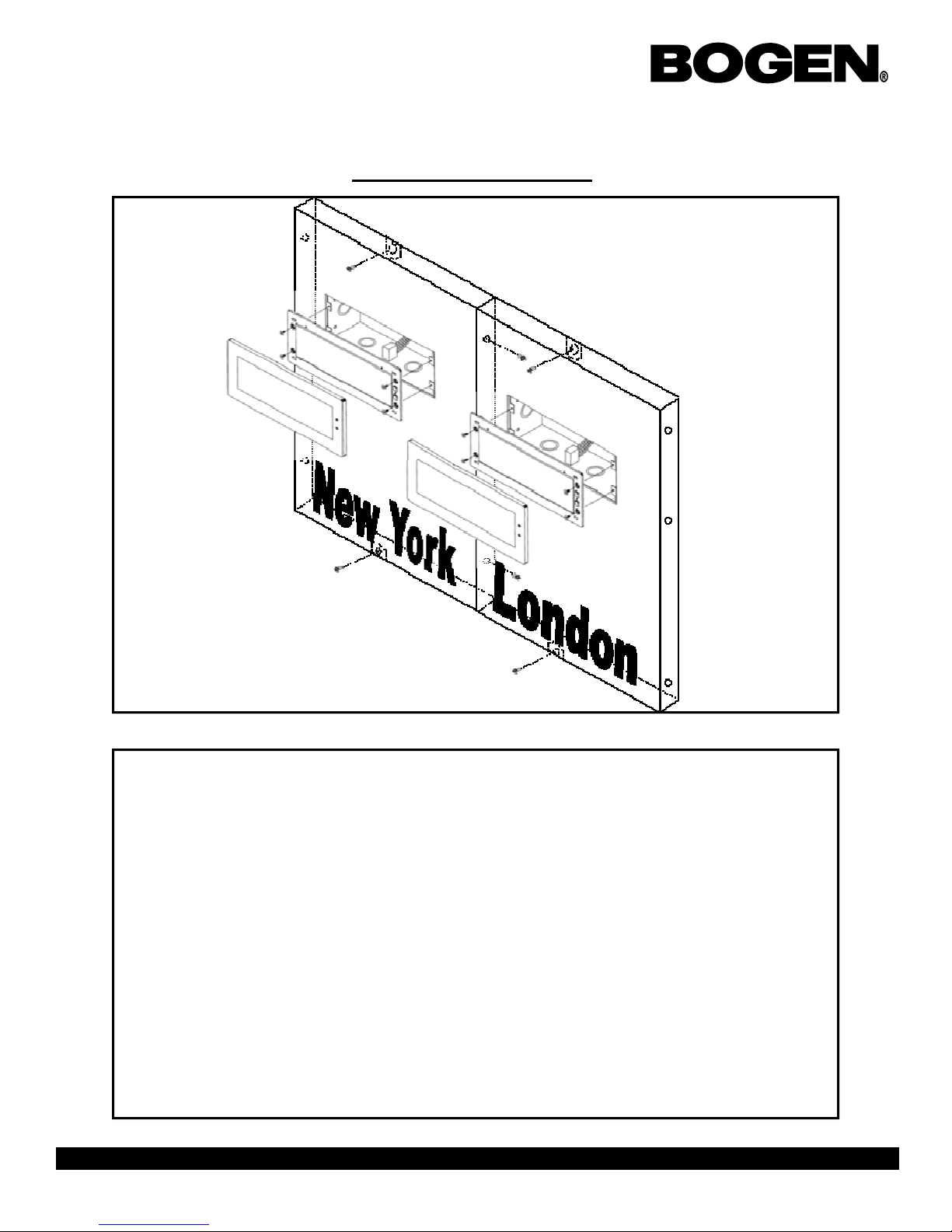
Mounting Instructions
Instructions
1. Wire the unit(s) as designated in the system wiring diagrams.
2. If mounting multiple housings together is desired, screw in the three locations on the side
panel of the housing.
3. Measure the distance of the mounting points on the housing.
4. Plug in the connector(s) to the clock movement.
5. Mount the plastic anchors into the wall.
6. Screw in the 10 x 1.5 sheet metal screw into the anchors.
7. Hang the clocks on to hooks on the top and bottom of the housing.
Page 2
50 Spring Street, P.O. Box 575, Ramsey, New Jersey 07446 Tel: 201-934-8500, Fax: 201-934-9832, Web Site: www.bogen.com
Page 3

BCBZ Series Zone Clock Installation Manual
Jumper Settings
JP1 JP2 JP3
24 Volts
110 Volts
Ground
110 Volts
24 Volts
JP1 JP2 JP3
12/24 Hour
Mode
ON: 12 hour mode
OFF: 24 hour mode
Brightness Loss of
Communication
ON: Brightest
OFF: Bright
ON: 5 minutes
OFF: 1 hour
Alert
50 Spring Street, P.O. Box 575, Ramsey, New Jersey 07446 Tel: 201-934-8500, Fax: 201-934-9832, Web Site: www.bogen.com
Page 3
Page 4

BCBZ Series Zone Clock Installation Manual
Setting The Hour
+
-
The top button is the positive offset. The bottom button is the negative offset.
Press the top button to advance the hour to the user’s preference for a positive offset.
Press the bottom button to advance the hour to the user’s preference for a negative offset.
50 Spring Street, P.O. Box 575, Ramsey, New Jersey 07446 Tel: 201-934-8500, Fax: 201-934-9832, Web Site: www.bogen.com
Page 4
Page 5

BCBZ Series Zone Clock Installation Manual
Frequently Asked Questions
Can the BCBZ series digital clock be used as an in dependent c lock?
No, the BCBZ zone clock requires communication input and must be used with one of the Sapling Master
Clocks, the BCSM Master Clock, the BCBD 2000 or the BCGPS.
What protocols can be run on the BCBZ series di gital z one clock?
The BCBZ series zone clock can use a 2 wire digital communication system or RS485 protocol can be
utilized. Please refer to system information for wiring diagram s.
How many clocks can be run on the same communication line using an RS485 protocol? What is
the maximum distance between clocks on the communication line?
Each BCBZ 1000 digital clock has an input and an output port. Each output port can drive up to 32 clocks
in parallel. When using a daisy chain method of communication (see drawing in the RS485 system information) you can run an unlimited number of clocks on the same communication line by connecting the
clocks to each other individuall y w here each clock drives the next clo c k i n li ne. When using a daisy chain
method of connection for communication, the maximum distance between each clock can be up to 3,000
feet. When an output drives mo re than one clock in parallel, the combined length of all the lines emanating from one clock can not exceed 3,000 feet.
How can I display "BELL" and "FirE" on the clock?
"BELL" displays can be programmed by either the Sapling 2000 or 3000 series Master Clocks. To display "FirE", a 3000 series master clock must be used which receives a signal from an existing alarm system.
What happens if voltage on the power line drops from 24 VAC (24 volt model) to a lower voltage?
The clock will still function, and will maintain the same level of brightness. However, the current consumption will increase proportionately to the decrease in voltage.
50 Spring Street, P.O. Box 575, Ramsey, New Jersey 07446 Tel: 201-934-8500, Fax: 201-934-9832, Web Site: www.bogen.com
Page 5
Page 6

BCBZ Series Zone Clock Installation Manual
Troubleshooting
The clock is not running, what do I d o?
a) Measure the input voltage to the clock. The voltage should measure 85-135 volts in the 110 volt
model or 10-28 volts in the 2.5”/24 vo lt model and 16 -28 volt in the 4.0”/24 volt model .
b) Make sure the transformer is an isolate d transf orme r if usi ng a 2 4 volt m odel.
c) Make sure the ground wire is not touching other wires.
If you fail to follow the instr uctions in a an d b lis ted abo ve, the fuses can be blow n.
The clock is not receiving an input signal, what do I do?
a) Make sure that the RS485 is connec ted properl y when using in RS4 85 slave m ode.
b) Make sure that the polarity of t he c ommunicat ion wire is co rrect when using the cl ock i n 2- wire digi-
tal communication slave mode.
c) If using 2 wire digital co mmunication , ma ke sure the clocks are the 24 volt m odel.
There is data noise bleeding into the intercom line, what do I do?
Reduce the transmission rate from the master clock to once a minute.
50 Spring Street, P.O. Box 575, Ramsey, New Jersey 07446 Tel: 201-934-8500, Fax: 201-934-9832, Web Site: www.bogen.com
Page 6
 Loading...