

Page 1
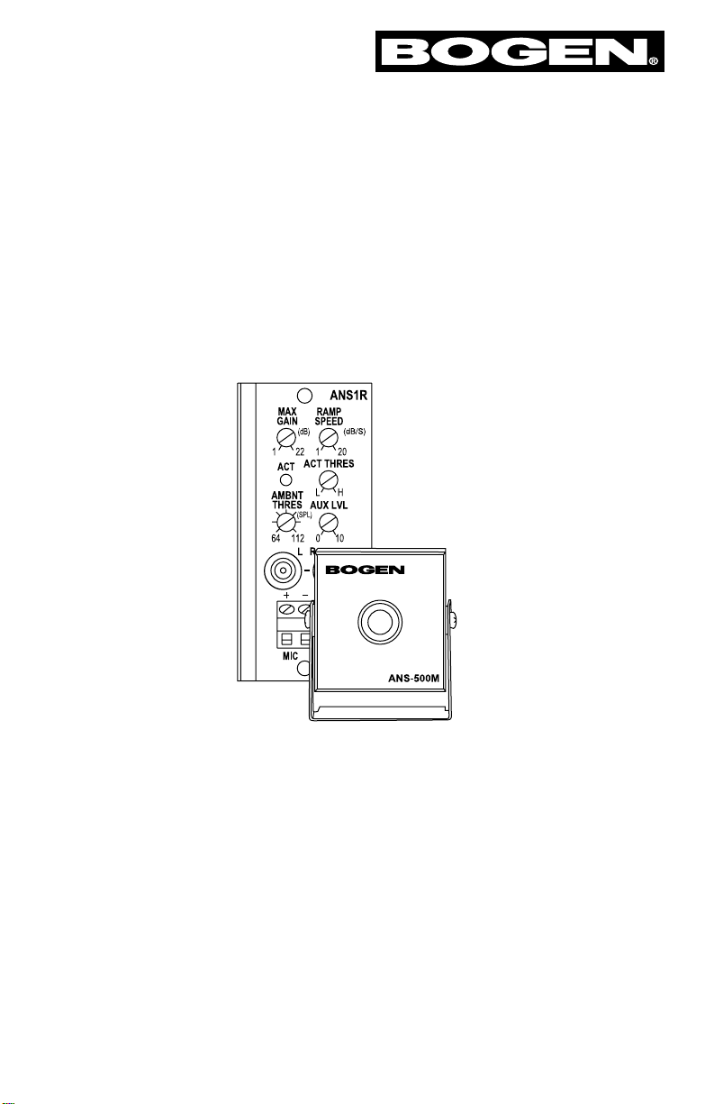
ANS1R
Ambient Noise Sensor Output Module
© 2002 Bogen Communications, Inc.
54-2067-01B 0403
Specifications subject to change without notice.
Page 2
Package Contents
1 - ANS1R Module
1 - ANS500M Sensor Microphone
2 - Module Screws
1 - Instruction Manual & Warranty
Module Features
• Maximum gain control
• Gain ramp speed control
• Activity threshold control
• Ambient MIC input threshold control
• Stereo unbalanced AUX inputs (summed
mono) with low priority
• AUX input can bypass gain control function
• AUX input level control (active in AUX input
processing “Bypass Mode” only)
• Compact sensor microphone (one included)
• Connect up to 4 sensor microphones for
large area coverage
• Remote defeat connections
• Gradual fade back from mute for AUX IN
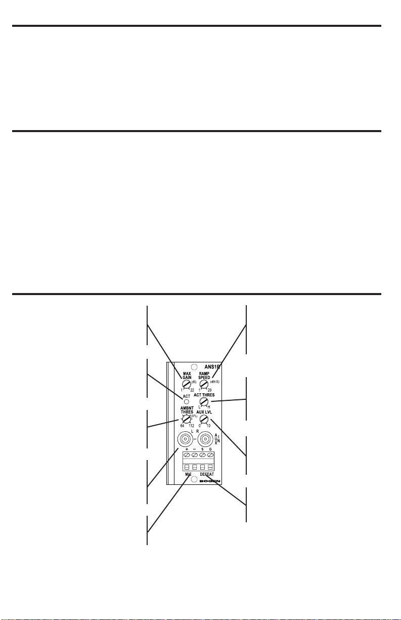
Module Front Panel Controls & Connectors
Maximum Gain
Sets the maximum amount of gain
added. Range of 1 dB to 22 dB of
added gain.
Activity LED
Bi-color LED illuminates when different thresholds are triggered to assist
in setup.
Ambient Threshold Control
Adjusts the microphone ambient
noise input threshold from 64 dBspl to
112 dBspl.
AUX Input
Mono summing, stereo, unbalanced
RCA inputs. The input can be used as
a normal input or set to bypass the
gain adjustment process of ANS1R.
MIC (Sensor)
Connections to ANS500M sensor
microphone(s) are made here.
Ramp Speed
Sets the speed by which gain is
increased or decreased to the signal,
from less than 1 dB/s (slow) to greater
than 20 dB/s (fast).
Activity Threshold
Activity threshold is set just above
typical operating level of the program
material applied to the gain processing
stage ANS1R.
AUX Level Control
Controls the input source level when
internal jumper is set to Bypass mode
(AUX signal bypasses gain riding).
Defeat
The effects of the ANS1R will be
defeated when these terminals are
shorted together.
2
Page 3
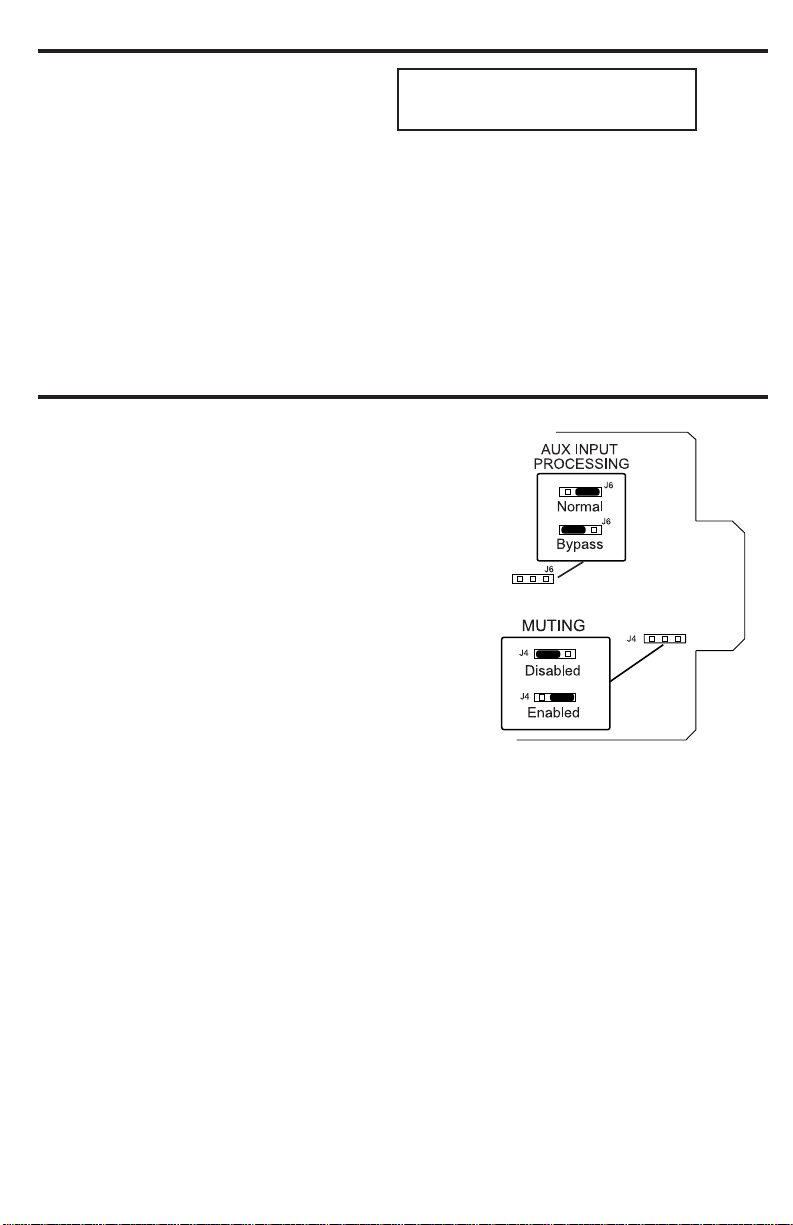
Jumper Selections
AUX Input Signal-Processing Jumper
• The AUX input available on the module can be set
to feed its signal to the amplifier’s front level control by setting the jumper in the “Normal” position.
The signal applied to this input will eventually be
processed to the gain riding function of the ANS1R
like every other input installed in the amplifier.
• By setting the jumper to “Bypass” position, the AUX
input will not be affected by any gain level changes
of the ANS1R.The amplifier’s front panel level con-
trol will be inactive when the module is set in this
mode. Any AUX signal level adjustment must be
made using the module’s AUX LVL control.
There are situations where it may be undesirable for
this AUX input to be affected by the gain riding function of the ANS1R. A typical exam-
ple would be where low level background music is desired in a lounge when there are
only a few people present.When the lounge is crowded and the ambient noise level is
high, it is not desirable for the background music level to increase since it will only add
to the high ambient noise. This is a case where the AUX input “Bypass” setting would
be appropriate.
Muting Jumper
Jumper placement only affects the module’s unbalanced input signal.The jumper placement
determines whether the module’s input can be muted by other input modules or not.
When enabled, the input is permanently set to the lowest priority level. When disabled,
the module will not respond to mute signal and remains active continuously.
Module Installation
1. Turn off all power to the unit.
2. Make all necessary jumper selections.
3. Position module in front of desired
output module bay opening, making sure that the module is right-side up. Output
modules will not fit in an input module bay. Do not force an output module into an
input module bay.
4. Slide module on to card guide rails. Make sure that both the top and bottom guides
are engaged.
5. Push the module in to the bay until the faceplate contacts the unit’s chassis.
6. Use the two screws included to secure the module to the unit.
WARNING:
Turn off power to unit and make all jumper
selections before installing module in unit.
3
Page 4

Sensor Microphone Connections
Sensor Microphone Wiring
• The ANS1R requires connection of at least one sensor microphone (ANS500M) for
operation.To allow for better ambient noise sensing of large areas, up to 4 sensor
microphones can be connected to a single ANS1R module.
• All microphones are wired in parallel matching the polarity markings on the sensor mic
with the marking of the two MIC terminals on the ANS1R.
To Other Microphones
(4 Max Total)
Wiring Details - ANS1R and Microphones
Wiring Multiple Microphones
Physical connections can be made using either Home Runs back to the module from
each sensor or by daisy-chaining sensors, depending on the installation. The maximum
total wire length from sensor mics to the ANS1R must be kept below 2000 ft.
Total Max Wire Length 2000 ft.
Max Run Length 2000 ft.
(Each Run)
4
Daisy Chain
Style Wiring
Home Run
Style Wiring
Page 5

Module Setup
Normal Mode:
In this mode, all inputs into the system from other modules and the ANS1R module’s AUX
input will be affected by the automatic gain adjustments of the ANS1R.
An AUX input is provided on this output module so that when it is installed the input function of the module bay is not forfeited. When this module is set for “Normal Mode”, the
front panel control of the unit functions normally, controlling the level of the source
plugged into the module’s AUX input. This input signal is applied to the unit’s mix bus like
all other input signals and is applied to the gain adjusting process of the ANS1R.Therefore,
the input applied to the ANS1R’s AUX input, in this mode, will be affected by the gain
adjusting process just like all the other inputs in the unit.
Note: When the AUX Input Processing jumper is in the “Normal” position, the AUX LVL control on
the ANS1R module will be inoperable and the module bay’s front panel control will function.
1. Ensure that the AUX Input Processing jumper (J6) is in the “Normal” position (this is
optional if the ANS1R’s AUX Input will not be used).
2. Connect all input sources to their respective inputs on the unit.
3. Set the desired levels of all the inputs using the unit’s front panel level controls (the
ANS1R module’s AUX LVL control is inoperable in this mode).
Go to Step 4 on next page.
Bypass Mode:
In this mode, all inputs into the system from other modules, but not
the AUX input on this
module, will be affected by the automatic gain adjustments of the ANS1R.
In audio systems that provide continuous background music, it may be desirable to have
the background music stay at a fixed level but have all other amplifier inputs (like a paging
microphone) change level in response to the ambient noise level in an area. Background
music is typically provided to make a venue seem less empty during slow periods or to help
cover conversation during quiet times. It is often undesirable to have this background
music level increase as ambient noise increases since it only adds to the overall noise in the
area. The ANS1R provides a means to bypass its AUX input around the gain adjustment
process so that it does not change with ambient noise levels.
Note: When the AUX Input Processing jumper is in the “Bypass” position, the module bay’s front
panel control will be inoperable and the AUX LVL control on the ANS1R module will function.
1. Ensure that the AUX Input Processing jumper (J6) is set to the “Bypass” position.
2. Connect the background music source to the module’s RCA jacks.
3. Set the background music to the desired operating level using the modules AUX LVL
control (the front panel input level control for the installed bay is inoperable in this
mode).
Setup continues on next page.
5
Page 6

Module Setup - Continued
4. Set the ACT THRES control to a point just before the ACT LED flashes amber. If audio
activity is intermittent, see Operating In Systems With Intermittent Audio Activity.
5a. Using the chart and diagram on page 7, set the AMBNT THRES to the dBspl level
where automatic increases to the system volume would be desired; or
5b. If the live ambient noise level while making these adjustments is at the desired trip
point, then adjust the AMBNT THRES control to a point where the ACT LED flashes
green.
6. Adjust the MAX GAIN to limit the maximum amount of gain the ANS1R can add to
the system.
7. Adjust the RAMP SPEED control to the desired amount of signal gain per second
(dB/s). Lower gain per second (dB/s) settings allows for gradual increases and decreases and ignores short bursts of noise. Higher gain per second (dB/s) settings allow the
system to react quickly to shorter bursts of noise.
8. Test the system’s response to noise and,if necessary,set the ACT THRES control high-
er if the maximum signal level is not achieved. Tweaking adjustments to Max Gain and
Ramp Speed controls may also be necessary.
Operation In Systems With Intermittent Audio Activity
The ANS1R monitors the audio activity on the mix bus of the main unit. Using this infor-
mation and the ambient noise level information, it regulates the amount of gain added to
the system. This manner of operation allows the proper amount of gain to be added to
keep the sources at the desired intelligible level without allowing it to become too great.
When working in systems that do not have continuous mix bus signals, like simple paging
systems, the ANS1R will behave differently than mentioned above. In these types of systems, when the ambient noise threshold has been exceeded, the ANS1R will ramp up to
the max gain setting during the time when there is no signal on the mix bus.When audio
activity appears on the bus, the ANS1R may begin to reduce system gain, at the RAMP
SPEED rate, in an attempt to reach an optimum sound level.
With this type of intermittent audio operation, the setting of the MAX GAIN and RAMP
SPEED controls will be the major factors in the operation of the system.The MAX GAIN
should be set for a level that will allow the paging to sound intelligible over the worst case
noise but not higher. The RAMP SPEED should be set to match the type of response to
noise changes wanted. If it is for an area with loud machinery that turns on and off, then a
fast ramp,10-20dB/s, would be applicable. If it is an area where the noise gradually rises and
lowers, then a slow ramp speed, 1-5 dB/s, would be used.The slower ramp speed keeps the
system from boosting gain when short loud noises are encountered.
6
Page 7

Ambient Threshold Control
(Detailed Markings)
Ambient Level Settings
Use this table to estimate the general
dBspl level of the area’s ambient noise if
no actual measurements are available.
Because of space limitations on the front
panel, detailed calibration markings for the
Ambient Threshold Control do not exist.
Use this figure as a setting reference.
Electrical Specifications
Gain (Boost) 0 dB to 22 dB (± 1 dB)
Frequency Response 5 Hz to 80 kHz (+0 / -3 dB)
S/N (20 Hz - 20 kHz) -96 dBV
Distortion <0.007%
Input Impedance (Aux) 20 k-ohms
Gain Ramp Speed 1 dB/s to 20 dB/s
Power ± 24 V DC
AUX Muting Level -50 dB
Controls Maximum Gain, Gain Ramp Speed, Activity Threshold,
Ambient MIC Input Threshold, & Auxiliary Level
Priority Level 4 only (for AUX IN)
Connector (2) RCA types & 4-position barrier strip
Weight 2.8 oz.
Dimensions 1
3
/8" W x 31/8" H x 31/2" D
7
Approximate
Noise Level Ambient Noise
Description Level (dBspl)
Very Quiet Restaurant/Bar 55
Hotel Lobby
Conversational Speech 60
Closed Supermarket
Department Store 70
Partially Filled Restaurant/Bar
Open Supermarket
Bus/ Transit Waiting Area 75
Crowded/Full Restaurant/Bar
Very Noisy Restaurant/Bar
Crowded Bus/Transit Waiting Area 80
Printing Shop
Machine Shop 85
Loud Machine Shop 90
Construction Site
Page 8

Block Diagram
50 Spring Street, Ramsey, NJ 07446, U.S.A.
Tel. 201-934-8500; Fax: 201-934-9832; www.bogen.com
 Loading...