


Boekel InSlide Out™
Hybridization Oven
Models
241000 and 241000-2
Operating Instructions
N2400117 Rev. 4 01/2013

CONTENTS
Page
1. Safety .............................................................................................................................. 2
2. Product Information ........................................................................................................ 3
3. Assembly......................................................................................................................... 3
3.1 Unpacking ....................................................................................................................... 3
3.2 Installation....................................................................................................................... 3
4. Operation......................................................................................................................... 3
4.1 Controls and Indicator Lamps (see Figure 1). ................................................................ 3
4.2 Setting the Temperature .................................................................................................. 4
4.3 Loading Tray with Slides ................................................................................................ 4
4.4 Loading Tray into Heating Chamber .............................................................................. 4
4.5 Removing Tray from Heating Chamber ......................................................................... 5
5. Accessories ..................................................................................................................... 5
5.1 Slide Holder .................................................................................................................... 5
6. Fault Diagnosis ............................................................................................................... 6
7. Technical Specifications ................................................................................................. 6
8. Maintenance and Service ................................................................................................ 7
8.1 Cleaning .......................................................................................................................... 7
8.2 Replacement of Fuses ..................................................................................................... 7
9. Warranty ......................................................................................................................... 8
10. Service............................................................................................................................. 8
1

1. Safety
The following symbols marked on the equipment mean:
Caution: Read these operating instructions fully before use and pay particular
attention to sections containing this symbol.
Attention: Suivre attentivement les instructions avant l’usage et prêtez une attention
particulière aux sections comportant ce symbole.
Caution: Surfaces can become hot during use.
Attention: Les surfaces peuvent devenir brûlantes pendent l’usage.
Caution: Risk of electric shock. Before attempting any service to this unit remove
power cord from the rear of the unit.
Attention: Risque électrique! Débrancher la prise arrière de réparer l’appareil.
Always observe the following safety precautions:
• Use only as specified by the operatin g instructions or the intrinsic protection may
be impaired. After transport or storage in humid conditions, dry out the unit
before connecting it to the supply voltage. During drying out the intrinsic
protection may be impaired. Allow unit to dry out for 4 hours minimum.
• Connect only to a power supply with a voltage corresponding to that on the serial
number label.
• Connect only to a power supply that provides a Protective Earth terminal.
• Before moving, disconnect at the power supply socket. Do not remove the plug.
• Do not check the temperature by touch, but instead use the temperature display.
• To reduce the risk of eye injury during high temperature operation, use safety
goggles or spectacles.
• Do not touch surfaces that become hot during high temperature operation.
• To protect from fire and other possible hazards, ensure that the operating
temperature is less than the maximum operating temperature of your sample
material.
• Ensure that the power switch is easily accessible during use.
• If liquid is spilled inside the unit, disconnect it from the power supply and have it
checked by a competent person.
• It is the user’s responsibility to carry out appropriate decontamination if
hazardous material is spilled on or inside the equipment.
• The Power Cord supplied with the unit is the disconnect means.
2

2. Product Information
The InSlide Out Hybridization Oven is designed so its sealed tray maintains a humid
condition for In-Situ Hybridization applications without the need to use sealed cover slips.
Uses include in-situ RNA amplification, reverse transcription reactions and hybridizations,
and immunohistochemical reactions.
The InSlide Out can hold up to twenty standard microscope slides on the standard wire
rack. An optional slide holder can hold up to eighteen standard microscope slides. The
unit has an advanced PID t emperatu re contro ller t hat provid es stable an d accu rate ch amber
temperatures from ambient plus 10˚C to 75˚C. The unit utilizes a sealed tray to create a
humid environment for overnight runs or weekend runs, depending on the operating
temperature.
3. Assembly
3.1 Unpacking
Remove packing materials carefully, and retain for future shipment or storage of the unit.
Inspect for damage. Report all shipping damage to the carrier immediately. Shipping
damage is covered b y the carrier and r epair/replacement for shipping d amages must be
coordinated through the carrier. Complete and return the Warranty Registration Card.
Packs should contain:
• In Slide Out Hybridization Oven
• Power Line Cord
• Operating Instructions
• Tray Assembly (includes tray with gasket installed and lid)
• Frame Assembly (held in place during shipping with corrugated spacer)
• Wire Rack (shipped inside the Tray Assembly)
• Filter Paper
3.2 Installation
Place the InSlide Out on a flat and stable s urface, preferably away from drafts. Fit the
power line cord into the IEC power socket on the rear of the unit. Plug power cord into a
power supply that matches the voltage listed on the serial number label on the rear of the
unit.
4. Operation
4.1 Controls and Indicator Lamps (see Figure 1)
The Power Switch controls power to the unit.
The temperature display shows the chamber temperature in degrees Celsius.
3
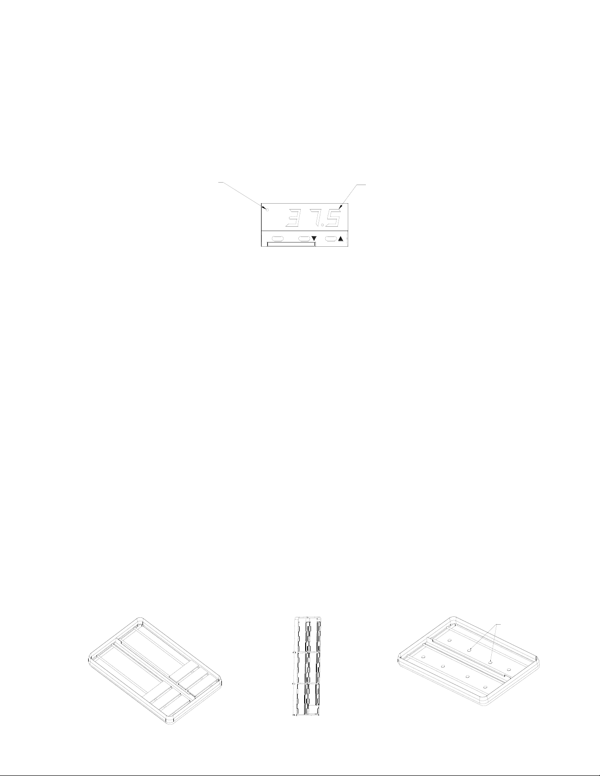
Figure 4
and Filter Paper
Buffer Solution
Figure 2
The heater lamp is on continuously while the Oven is heating up. As the required
Figure 3
temperature is approached, it starts to flash. When the unit is controlling at the set
temperature, the heater lamp flashes intermittently.
Heater
Lamp
4.2 Setting the Temperature
The Temperature Controller has three buttons. When the button on the left ‘*’ is
depressed, it will display the set temperature. When the left button ‘*’ is depressed
simultaneously with the middle button ‘▼’, the set temperature value is lowered. When
the left button ‘*’ is depressed simultaneously with the right button ‘▲’, the set
temperature value is raised. When all buttons are released, the actual chamber
temperature is displayed.
In the event of power loss, the Temperature Controller retains the last set temperature
value.
Temperature
Display
*
Figure 1
4.3 Loading Tray with Slides
The tray with th e standard wire rack can be loaded with up to 20 standard glass slides
(see Figure 2). Using the optional slide holder, up to 18 standard glass slides can be
loaded (see Figure 3). Use your standard protocol to prepare the slides with probe and
buffer. Place filter paper at the bottom of the tray (Whatman* filter paper, Catalog
Number 1823 025, is recommended). To provide humidity during the heating c ycle, add
approximately 2 ml of currently used hybridization solution on the filter paper in the
bottom of the tray (see Figure 4). Do not use water or distilled water. If cover slips are
used, it is not necessary to seal them; the hybridization solution and the sealed tray
maintain a humid environment.
*Whatman is a trademark of Whatman International Ltd.
4
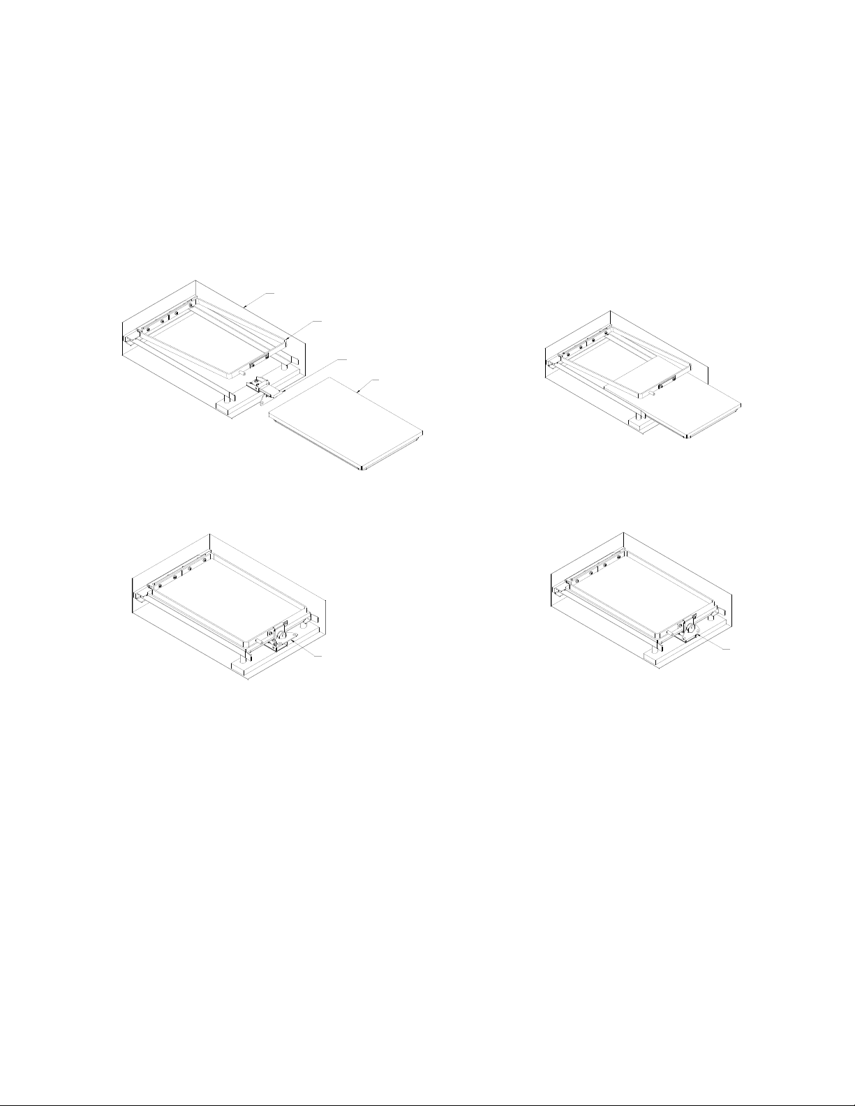
4.4 Loading Tray into Heating Chamber
Once the Tray Assembly is loaded and the slides prepared, the tray can be loaded into the
heating chamber. Open the main door, lift the frame, pivot the latch forward (see Figure
5), and slide the Tray Assembly into the Frame Assembly until it is fully seated against
the rear of the Frame Assembly (see Figure 6). Rotate the latch into a vertical position
and position the latch over the keeper on the frame, then rotate the Latch Handle 180˚
clockwise (see Fi gure 7). R otate the Latch Handle down (see Figure 8). Cl ose the main
door.
Heated
Chamber
Frame
Assembly
Latch
Tray
Assembly
Figure 6
Figure 5
(Tray partially inserted)
Latch
Handle
Figure 7
(Fully inserted and locked)
4.5 Removing Tray from Heating Chamber
Extreme care must be used when removing the tray due to the potentially high
temperature. It may be necessary to use gloves when removing the tray. To remove the
tray from the Heating Chamber, open the main door, lift the Latch Handle up and rotate it
180˚ in a counter clockwise direction. Rotate the latch down, lift the frame up and
carefully slide the Tray Assembly out.
5. Accessories
5.1 Slide Holder – Catalog Number C2403765
This slide holder is made from polycarbonate and will hold 18 standard glass slides.
5
Latch
Handle
Figure 8
(Ready to close main door)

6. Fault Diagnosis
Symptom
Possible Cause
Action Required
1. Unit does not operate
a. Unit not switched on
a. Switch on
2. Chamber temperature does
a. Actual temperature is
a. Check set temperature
3. Temperature continues to
a. Actual temperature is
a. Check set temperature
4. Slides dry out during
a. Gasket not sealing
a. Replace Tray and Gasket
tighten Latch
not rise when expected
rise when not expected
heating cycle
b. Unit not plugged into
power supply
c. Fuses blown
d. Power supply failure
higher than set
temperature
b. Temperature control
circuit fault
lower than set temperature
b. Temperature control
circuit fault
b. Lid bent
c. Insufficient buffer placed
in bottom of tray
d. Latch not fully engaged
b. Plug in, switch on
c. Replace fuses per 8.2
d. Check that other electrical
appliances on the same
circuit are working
b. Have unit checked by
competent person
b. Have unit checked by
competent person
Assembly
b. Repl ace Lid
c. Place more buffer in
bottom of tray
d. Re-install Tray Assembly
into chamber and re-
7. Technical Specifications
This equipment is intended for indoor use and will meet its performance figures within the
ambient temperature range of 10°C to 35°C, with maximum relative humidity of 80% (noncondensing). Installation Category II (transient voltages). Pollution Degree 2 in accordance
with IEC 664. Suitable for operation at altitudes of up to 6500 feet.
6

Specifications:
Temperature Range: (Ambient +10°C) to 75°C
Setting Range: 0°C to 75°C
Stability: +/- 0.2°C
Overall Accuracy: +/- 0.5°C at 65°C
Temperature Display Resolution: 0.1°C
Supply Voltage Range: 115V +/- 10%, 1.35A, 60 Hz
230V +/- 10%, 0.67A, 50/60 Hz
Power Rating: Model 241000: 155W
Model 241000-2: 155W
Heating Rate: Ambient to 50°C within 20 minutes
8. Maintenance and Service
All Boekel laboratory products are designed to comply with IEC1010-1. No routine
maintenance is required.
8.1 Cleaning
Disengage power cord prior to cleaning. If a spill occurs, use appropriate clean up
procedures as required for radiation or biohazard control. The outer casing may be
cleaned with water and a damp cloth. Do not submerge or immerse the InSlide Out in
water. Before using an y cleanin g or decontamination method except those recommended
by the manufacturer, users should check that the proposed method would not damage the
equipment.
7

8.2 Replacement of Fuses
There are two supply fuses located in the fuse drawer. To replace the fuses:
• Disconnect the unit from the power supply.
• Remove the plug from the socket in the back of the unit.
• Pull back on the fuse drawer (see Figure 11).
• Pull out the fuse drawer.
• Check and replace with the correct fuses if necessary. The fuses must be
5mm x 20mm quick acting, rated 250V.
Model 241000: -2AF
Model 241000-2: -1AF
• Push the fuse drawer back in. Reconnect unit to the power supply.
Fuse
Drawer
Figure 11
9. Warranty
When used in laboratory conditions and according to these operating instructions, Boekel
warrants this product to be free of defective material and workmanship for a period of two
years from the date o f manufacture. The liabili ty of Boekel for any defectiv e equipment
during the warrant y period shall be limited to the repair of such equipment or replacement
thereof without charge for parts or labor.
10. Service
A Returned Goods Authorization (RGA) number must be obtained before any Boekel
products are returned for any reason. A Decontamination Notice must be completed,
signed by the user, and returned to Boekel Scientific prior to receiving the RGA number.
Please be sure to mark the outside of the return goods package with this RGA number to
ensure prompt handling.
Boekel Scientific
855 Pennsylvania Blvd.
Feasterville, PA 19053
PHONE: (215) 396-8200 or (800) 336-6929
FAX: (215) 396-8264
e-mail: boekel-info@boekelsci.com
website: www.boekelsci.com
8
 Loading...