

Body Solid GDR500PACK User Manual

®
by
by
®
GDR500
˚˗˥ˈ˃˃
T
able of Contents
Important Safety Instructions. . . . . . . . . . . p. 2
Before You Begin. . . . . . . . . . . . . . . . . . . . . . p.
A s s e m b l y I n s t r u c t i o n s
O W N E R ’ S M A N U A L
&
Dimensions. . . . . . . . . . . . . . . . . . . . . . . . . . . p. 4
Reference Drawings. . . . . . . . . . . . . . . . . . . p. 5
Warning, Safety and Maintenance. . . . . . . p. 6
Safety Guidelines. . . . . . . . . . . . . . . . . . . . . p. 7
Preparations. . . . . . . . . . . . . . . . . . . . . . . . . . p.
Assembly Instructions. . . . . . . . . . . . . . . . . p.
Exercise Tips. . . . . . . . . . . . . . . . . . . . . . . . . p. 20-39
Mainframe Parts List. . . . . . . . . . . . . . . . . . . p.
Hardware List. . . . . . . . . . . . . . . . . . . . . . . . . p.
Hardware (To Scale). . . . . . . . . . . . . . . . . . . p. 42-43
Exploded View Diagram. . . . . . . . . . . . . . . . p. 44-45
Notes. . . . . . . . . . . . . . . . . . . . . . . . . . . . . . . . . p. 46-47
3
8
9-19
40
41
v. 102810

I m p o r t a n t S a f e t y I n s t r u c t i o n s
Before beginning any fitness program, you should obtain a complete physical examination from your physician.
Il est conseille de subir un examen medical complet avant d’entreprendre tout programme d’exercise.
Si vous avez des etourdissements ou des faiblesses, arretez les exercices immediatement.
Antes de comenzar cualquier programma de ejercicios, deberias tener un examen fisico con su doctor.
When using exercise equipment, you
should always take basic precautions,
including the following:
m Read all instructions before using the GDR500.
These instructions are written to ensure your safety
and to protect the unit.
m Do not allow children on or near the equipment.
m Use the equipment only for its intended purpose
as described in this guide. Do not use accessory
attachments that are not recommended by the
manufacturer. Such attachments might cause
injuries.
m Wear proper exercise clothing and shoes for your
workout, no loose clothing.
m Use care when getting on or off the unit.
m Do not overexert yourself or work to exhaustion.
m If you feel any pain or abnormal symptoms, stop
your workout immediately and consult your
physician.
m Never operate the unit when it has been dropped or
damaged. Return the equipment to a service
center for examination and repair.
m Never drop or insert objects into any opening in
the equipment.
m Do not use the equipment outdoors or near water.
The GDR500 is designed for your enjoyment. By following these precautions and using common sense, you will
have many safe and pleasurable hours of healthful exercise with your Body-Solid GDR500.
After assembly, you should check all functions to ensure
correct operation. If you experience problems, first recheck the assembly instructions to locate any possible
errors made during assembly. If you are unable to correct
the problem, call the dealer from whom you purchased
the machine or call 1-800-556-3113 for the dealer nearest you.
Obtaining Service
Please use this Owner’s Manual to make sure that all
parts have been included in your shipment. When ordering parts, you must use the part number and description
from this Owner’s Manual. Use only Body-Solid replacement parts when servicing this machine. Failure to do so
will void your warranty and could result in personal injury.
For information about product operation or service, check
out the official Body-Solid website at www.bodysolid.com
or contact an authorized Body-Solid dealer or a Body-Solid
factory-authorized service company or contact Body-Solid
customer service at one of the following:
Toll Free: 1-800-556-3113
Phone: 1-708-427-3555
Fax: 1-708-427-3556
Hours: M-F 8:30-5:00 CST
E-Mail: service@bodysolid.com
Personal Safety During Assembly
m It is strongly recommended that a qualified dealer
assemble the equipment.
Assistance is required.
m Before beginning assembly, please take the time
to read the instructions thoroughly.
m Read each step in the assembly instructions and
follow the steps in sequence. Do not skip ahead.
If you skip ahead, you may learn later that you
have to disassemble components and that you
may have damaged the equipment.
m Assemble and operate the GDR500 on a solid,
level surface. Locate the unit a few feet from the
walls or furniture to provide easy access.
Or write to: Body-Solid, Inc.
Service Department
1900 S. Des Plaines Ave.
Forest Park, IL 60130 USA
Retain this Owner’s Manual for future
reference. Part numbers are required when
ordering replacement parts.
2

B e f o r e Y o u B e g i n
Thank you for purchasing the GDR500. This gym is part of the Body-Solid line of quality strength
training machines, which let you target specific muscle groups to achieve better muscle tone and
overall body conditioning. To maximize your use of the equipment please study this Owner’s Manual thoroughly.
Unpacking the Equipment
The GDR500 is carefully tested and inspected before
shipment. Body-Solid ships the unit in several pieces that
require assembly. Ask for assistance during the assembly
process.
Carefully unpack the boxes and lay the pieces on the floor
near the area where you plan to use the equipment.
Be careful to assemble all components in the
sequence presented in this guide.
If any items are missing, contact the dealer from whom
you purchased the unit or call 1-800-556-3113 for the
dealer nearest you.
Body-Solid continually seeks ways to improve the performance, specifications and product manuals in order to ensure that only superior products are released from our factories. Please take the time to carefully read through this manual thoroughly. Instructions
contained in this document are not intended to cover all details or variations possible with Body-Solid equipment, or to cover every
contingency that may be met in conjunction with installation, operation, maintenance or troubleshooting of the equipment. Even though
we have prepared this manual with extreme care, neither the publisher nor the author can accept responsibility for any errors in, or
omission from, the information given. Should additional information be required, or should situations arise that are not covered by this
manual, the matter should be directed to your local Body-Solid representative, or the Service Department at Body-Solid Inc. in Forest
Park, Illinois.
Any Questions?
Call (800) 556-3113
3
D i m e n s i o n s
3'8"
2'2"
3'10"
5'
4'
Suggested usage space
The room layout diagram below will help you decide the best placement for your GDR500.
The dimensions of the GDR500 are: Width 2’ 2” X Length 3’8”.
The usage space is: Width 4’ X Length 5’ (The usage space is the overall space needed for operation).
The usage space needed for the GDR500 could be more, depending on the user.
Dimensions
Height
4
R e f e r e n c e D r a w i n g s
Note: Due to continuing product improvements, specifications and designs are subject to change
without notice.
Even though we have prepared this manual with extreme care, neither the publisher nor the
author can accept responsibility for any errors in, or omission from, the information given.
5
W a r n i n g , S a f e t y & M a i n t e n a n c e
#!54)/.
'*/(&353"1
4(%2%)3!2)3+!335-%$"9).$)6)$5!,37(/53%4()3490%/&%15)0-%.4
4/-).)-):%2)3+9/5-534&/,,/74(%3%25,%3
*OTQFDUFRVJQNFOUCFGPSFFBDIXPSLPVU
$IFDLUIBUBMMOVUTBOECPMUTBSFJ OQMBDFBOEG VMMZUJHIUFOFE
"MTPCFGPSFVTFDIFDLGPSTJHOTPGXFBS3FQMBDFBMMXPSOQBSUTJNNFEJBUFMZ
/FWFSVTFFRVJQNFOUJGBOZ QBSUTBSFEBNBHFEPSNJTTJOH
&!),52%4/&/,,/74(%3%25,%3-!92%35,4).).*529
&YFSDJ TFXJUID BSF1FSGPSNZP VSFYFSDJTFBU BTNPPUI NPEFSBUF QBDFOFWFSQFSGPS NKFSLZPS
VODPP SEJOBUFEN PWFNFOUTU IBUNBZDBVTFJOKVSZ
%0/05 BMMPXDIJMESFOPS NJOPSTUPQMBZ POPSBSPVOEUIJTFRVJQNFOU
*GVOTVSFPGQ SPQFS VTFPGF RVJQNFOUDBMM ZPVS MPDBM#P EZ4PMJE EJTUSJCVU PSPSUIF#PEZ4PMJE
DVTUP NFSTFSWJDFDFOUFSBU
$POTVMUZPVSQIZTJDJBOCFGPSFTUBS UJOHZPVSFYFSD JTFQSPHSB N
'PSZPVSPXOTBGFUZ%0/05 CFHJOBOZFYFSDJTFQ SPHSBNXJU IPVUQSPQFSJO TUSVDUJPO
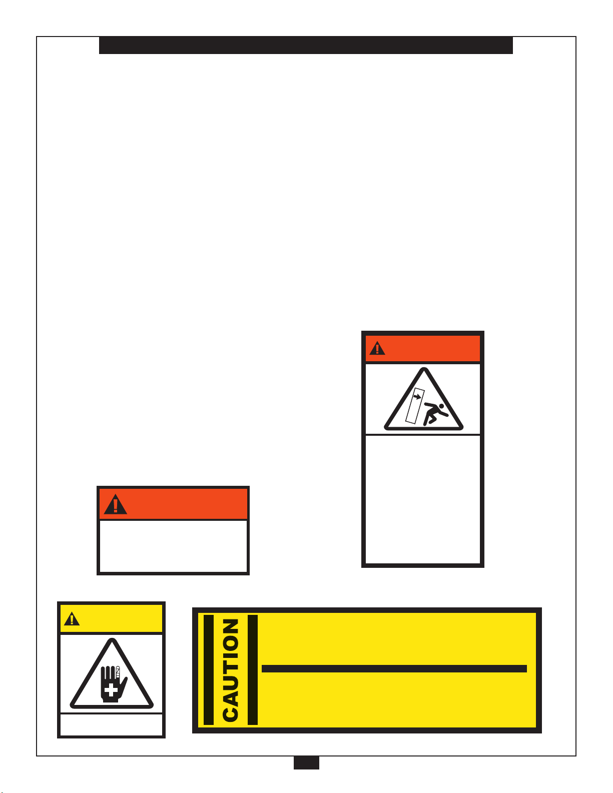
7!2.).'
5*107&3)";"3%
3AFETYBARANDLOCKING
PINSMUSTBEENGAGED
BEFOREMOVINGRACK
.EVERROCKTILTORCLIMB
ONUNIT
&AILURETOABIDEMAY
RESULTINDEATHOR
SERIOUSINJURY
."9-0"%
-#,(
7!2.).'
Precision craftsmanship assures Body-Solid’s ability to
consistently deliver products of the highest standards.
Our products have been carefully designed to ensure
safe, efficient long term operation.
However, it must be realized that safe use of this
equipment requires that owners carefully read and follow
the Body-Solid use recommendations, warnings, and
maintenance guidelines in this Owners Manual.
Routine inspection and maintenance is of critical
importance to ensure maximum safety and performance.
Body-Solid uses the highest quality materials available,
but wear is inevitable. Therefore, you must carefully
inspect your equipment.
Be advised that dangerous conditions can arise even
during a warranty period. A warranty does not negate the
owner’s responsibility to thoroughly, carefully and daily
inspect the machine.
Including maintaining the equipment, the owner’s
responsibility is also to:
m Be sure to always provide adequate supervision to
all end-users.
m Be sure to instruct all end-users of proper usage.
m Be sure all supervisors and personal trainers who
instruct end-users on equipment use are properly
trained and know the function and importance of
every adjustment and setting.
Also, be sure these trainers provide proper
instruction to end-users on the fundamentals of
strength training.
NUTS/BOLTS/FASTENERS:
m Periodically inspect all nuts and bolts. Tighten if
needed. If bolts seem to loosen periodically, use
Loctite 242 for a long-term cure.
m Go through a re-tightening sequence periodically to
ensure that all hardware is properly tensioned.
ADJUSTMENTS:
m Check all pieces for signs of visible wear or damage.
WARNING INSTRUCTION LABELS:
m Inspect and familiarize yourself with all safety
warnings and other user information on decals.
6

S a f e t y G u i d e l i n e s
Successful resistance training programs have one prominent feature in common... safety.
Resistance training has some inherent dangers, as do all physical activities. The chance
of injury can be greatly reduced or completely removed by using correct lifting techniques,
proper breathing, maintaining equipment in good working condition, and by wearing the appropriate clothing.
m It is highly recommended that you consult your physician before beginning any exercise
program. This is especially important for individuals over the age of 35, or persons with
pre-existing health problems.
m Always warm up before starting a workout. Try to do a total body warm up before you
start. It is especially important to warm up the specific muscle groups you are going to be
using. This can be as simple as performing a warm up set of high repetitions and light
weight for each exercise.
m Use proper form. Focus on only working the muscle groups intended for the exercise you
are doing. If there is strain elsewhere, you may need to re-evaluate the amount of weight
that is involved with the lift. Keeping proper form also includes maintaining control
through an entire range of motion.
m Breath properly. Inhale during the eccentric phase of the exercise, and exhale during the
lifting, or concentric phase. Never hold your breath during any part of an exercise.
m Always wear the appropriate clothing and shoes when exercising. Wearing comfortable
athletic shoes with good support and loose fitting, breathable clothing will reduce the risk
of injury.
m Maintaining equipment in proper operating condition is of utmost importance for a safe
resistance training program. Pulleys and cables should be checked for wear frequently
and replaced as needed. Equipment should be lubricated as indicated by the
manufacturer.
m Read and study all warning labels on this machine. It is absolutely necessary that you
familiarize yourself and all others with the proper operation of this machine prior to use.
m Keep hands, limbs, loose clothing and long hair well out of the way of all moving parts.
m Do not attempt to lift more weight than you can control safely.
m Inspect the machine daily for loose or worn parts. If a problem is found do not allow the
machine to be used until all parts are tightened or worn or defective parts are repaired or
replaced.
7

P r e p a r a t i o n s
CAUTION: To set up this unit, you will need assistance.
Do not attempt assembly by yourself.
You must review and follow the instructions in this Owner’s Manual. If you do not assemble and use the
GDR500 according to these guidelines, you could void the Body-Solid warranty.
Required Tools
The basic tools that you must obtain before assembling
the GDR500 include but are not limited to:
m Metric Allen Key Set
m Standard Allen Key Set
m Standard Wrench Set
m Metric Wrench Set
m Adjustable Wrench
m Screwdriver (standard and/or phillips)
m Rubber Mallet
m Silicone Spray Oil
Installation Requirements
Follow these installation requirements when assembling
the GDR500:
Set up the GDR500 on a solid, flat surface. A smooth, flat
surface under the machine helps keep it level. A level machine has fewer malfunctions.
CAUTION: Obtain assistance! Do not attempt to
assemble the GDR500 by yourself.
Review the Installation Requirements
before proceeding with the following
steps.
The GDR500 unit comes in one box. Be careful to assemble components in the sequence presented in this guide.
NOTE: With so many assembled parts, proper
alignment and adjustment is critical. While
tightening the nuts and bolts, be sure to leave
room for adjustments.
Provide ample space around the machine. Open space
around the machine allows for easier access.
Insert all bolts in the same direction. For aesthetic purposes, insert all bolts in the same direction unless specified
(in text or illustrations) to do otherwise.
Leave room for adjustments. Tighten fasteners such as
bolts, nuts, and screws so the unit is stable, but leave
room for adjustments. Do not fully tighten fasteners until
instructed in the assembly steps to do so.
Fill out and mail the warranty card.
8
A s s e m b l y I n s t r u c t i o n s
Assembly of the GDR500 takes professional installers about ½ hour to complete. If this is the first time
you have assembled this type of equipment, plan on significantly more time.
Professional installers are highly recommended!
However, if you acquire the appropriate tools, obtain assistance, and follow the assembly steps sequentially,
the process will take time, but is fairly easy.
Assembly Tips
Read all “Notes” on each page before beginning each
step.
While you may be able to assemble the GDR500 using the
illustrations only, important safety notes and other tips are
included in the text.
Some pieces may have extra holes that you will not use.
Use only those holes indicated in the instructions and illustrations.
IMPORTANT!
Before you begin you should look at the quick reference
guide that shows all hardware parts (in actual size) along
with the corresponding key numbers on the assembly instructions.
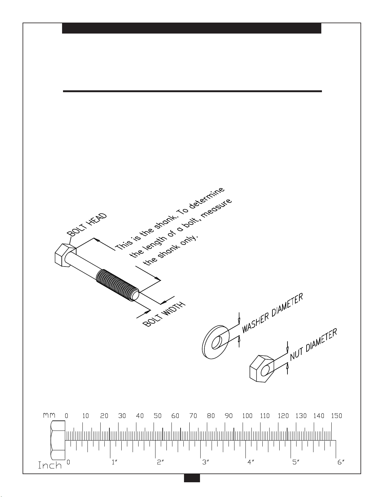
NOTE: To find out the length of a particular bolt,
measure its shank (the long, narrow part
beneath the head). Refer to the following
diagram:
Do not fully tighten bolts until instructed to do so.
NOTE: After assembly, you should check all functions
to ensure cor rect operation. If you experience
problems,rstr echecktheassemblyinstructions
to locate any possible error s made during assembly.
If you are unable to correct the problem, call the
dealer from whom you purchased the machine or
call 1-800-556-3113 for the dealer nearest you.
9

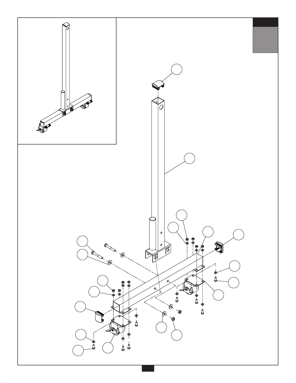
S T E P
1
Be careful to assemble all components
in the sequence they are presented.
NOTE: Tighten all hardware at the end of this step.
A. Insert Convex End Cap (11) into Upright (B).
B. Insert both Convex End Caps (11) into Side Frame (C).
C. Connect both Locking Wheels (12) to Side Frame (C) using:
Eight 3 (M8x20 hex head bolt)
Sixteen 9 (M8 washer)
Eight 7 (M8 nylon lock nut)
D. Attach Upright (B) to Side Frame (C) and secure using:
Two 2 (M10x70 hex head bolt)
Four 8 (M10 washer)
Two 6 (M10 nylon lock nut)
10
S T E P
B
2
8
6
8
C
1
1
12
12
9
3
7
9
7
9
3
9
11
11
11
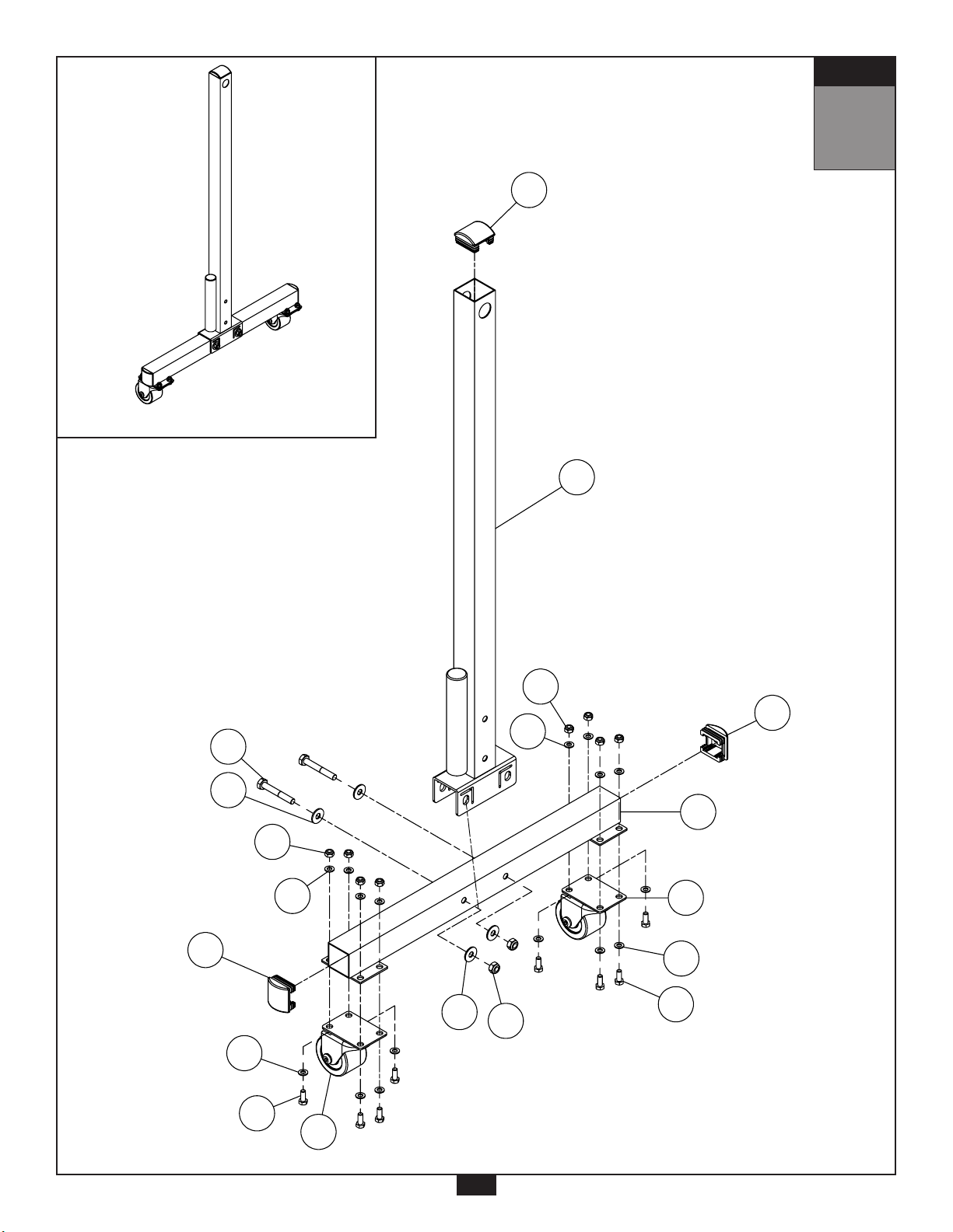
S T E P
1
11
S T E P
1
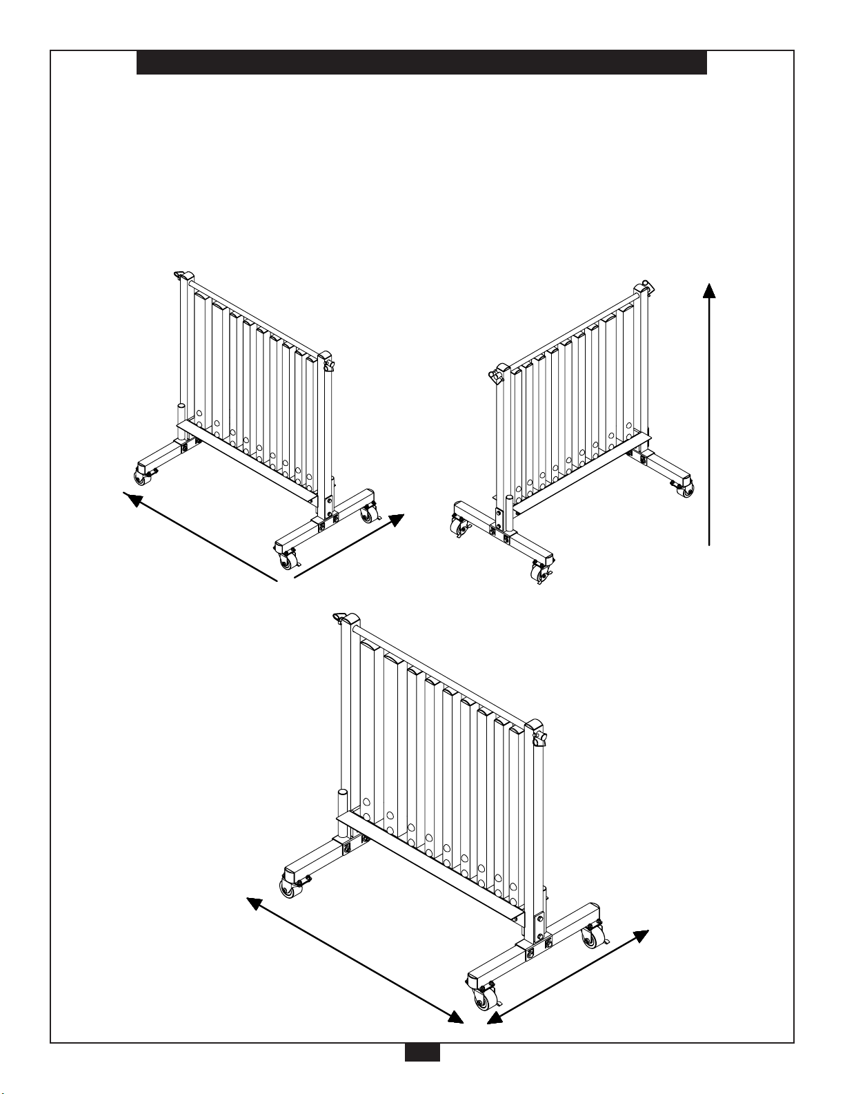
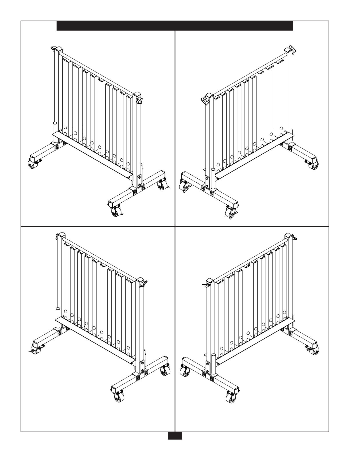
Above shows Step 1 assembled and completed.
11

S T E P
2
Be careful to assemble all components
in the sequence they are presented.
NOTE: Tighten all hardware at the end of this step.
A. Insert Convex End Cap (11) into Upright (B).
B. Insert both Convex End Caps (11) into Side Frame (C).
C. Connect both Wheels (13) to Side Frame (C) using:
Eight 3 (M8x20 hex head bolt)
Sixteen 9 (M8 washer)
Eight 7 (M8 nylon lock nut)
D. Attach Upright (B) to Side Frame (C) and secure using:
Two 2 (M10x70 hex head bolt)
Four 8 (M10 washer)
Two 6 (M10 nylon lock nut)
12
S T E P
2
11
S T E P
B
2
8
6
8
C
2
2
13
13
9
7
3
9
3
9
7
9
11
11
11
Above shows Step 2 assembled and completed.
S T E P
2
13

S T E P
3
Be careful to assemble all components
in the sequence they are presented.
NOTE: Tighten all hardware at the end of this step.
A. Connect Base Frame (A) and both Flat Plates (1) to both Uprights (B) as shown using:
Four 2 (M10x70 hex head bolt)
Four 10 (M10 washer)
NOTE: Ensure Base Frame (A) is assembled in the direction shown.
B. Insert both Flat End Caps (14) into both Large Rack Uprights (D).
C. Insert Large Rack Upright (D) onto Base Frame (A) and secure using:
Four 4 (M10x16 hex head bolt)
Four 10 (M10 washer)
Four 22 (cap)
D. Repeat Step 3 Section C above to install the remaining Large Rack Upright (D).
14
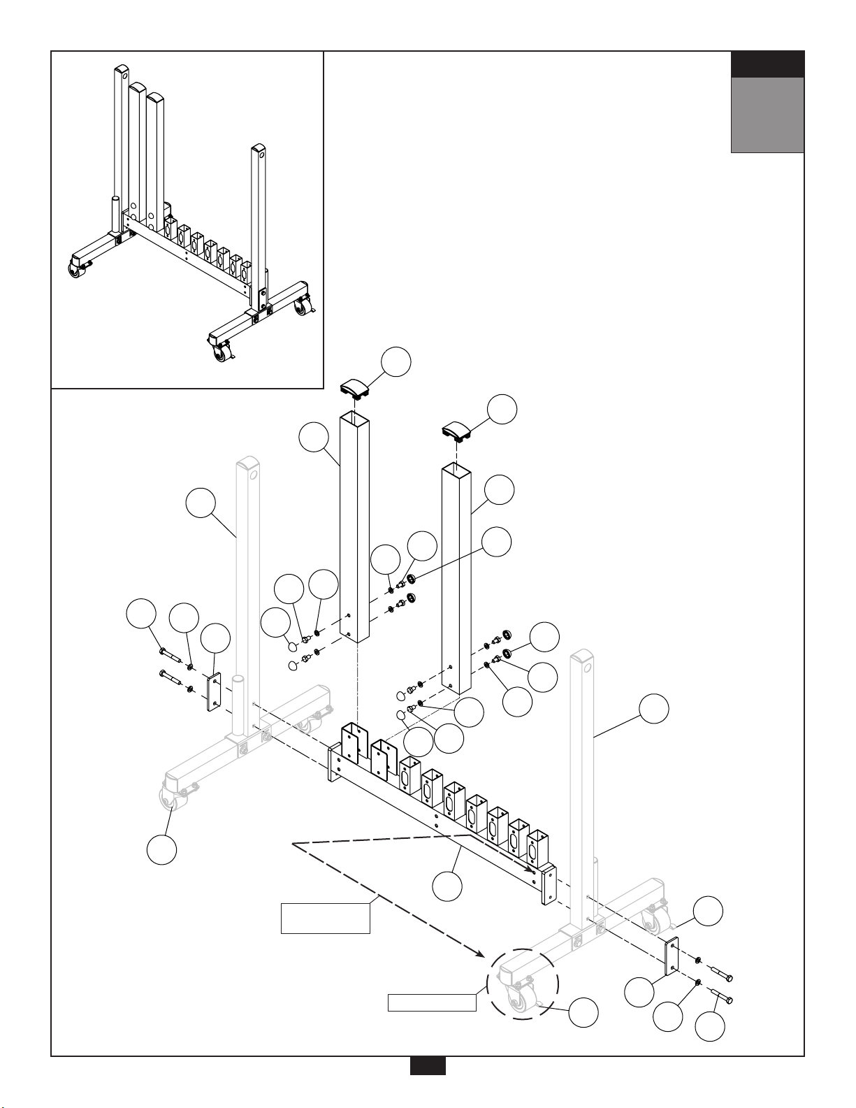
S T E P
Above shows STEP
assembled and completed
3
3
2
10
1
D
D
2
10
1
A
B
B
12
12
13
14
14
4
21
4
21
4
21
4
21
22
22
22
22
S T E P
3
S T E P
3
Above shows Step 3 assembled and completed.
Direction of
Base Frame (A).
Locking Wheel
15
 Loading...