

Page 1
by
Body-Solid
®
Assembly Instructions
Page 2

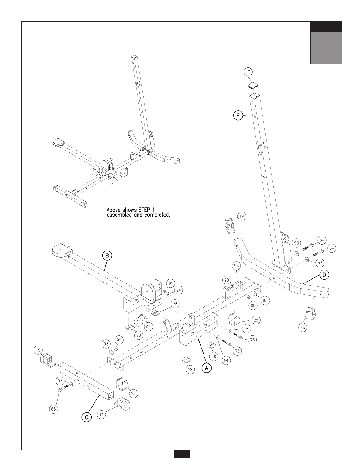
STEP
1
Be careful to assemble all components
in the sequence they are presented.
NOTE:
Finger tighten all hardware in this step. Do Not
A. Attach two Weight Stack Shims (28) to the bottom of Main Base Frame (A), and two Weight
Stack Shims (28) to the bottom of Side Base Frame (B). Also, install two Frame Levelers (25)
to the Main Base Frame (A) as shown.
B. Attach Main Base Frame (A) to Side Base Frame (B) using:
Two 73 (3/8”x 2 3/4” hex head bolt)
Four 94 (3/8” washer)
Two 91 (3/8” nylon lock nut)
C. Attach two Foot Caps (19) to the ends of Front Base Frame (C).
Attach Front Base Frame (C) to the Main Base Frame (A) using:
One 65 (1/2”x 3” hex head bolt)*
Two 93 (1/2” washer)
One 90 (1/2” nylon lock nut)
*NOTE:
Only use one bolt (65) as shown. You will need the other side open for step 5.
wrench tighten until end of step 5.
D. Attach one Foot Cap (19) to one end of Rear Base Frame (D). Leave the other side open,
(depending on which side of the gym you want the low pulley station).* Connect Rear Base
Frame (D) and Rear Vertical Frame (E) to Main Base Frame (A) as shown using:
Two 64 (1/2”x 3 1/4” hex head bolt)
Four 93 (1/2” washer)
Two 90 (1/2” nylon lock nut)
*NOTE:
Depending on how much space you have available, and the configuration of your
room, you can assemble this gym with the low pulley station on either side.
E. Attach End Cap (13) to the top of Rear vertical Frame (E) and Frame Leveler (25) to Rear
Base Frame (D).
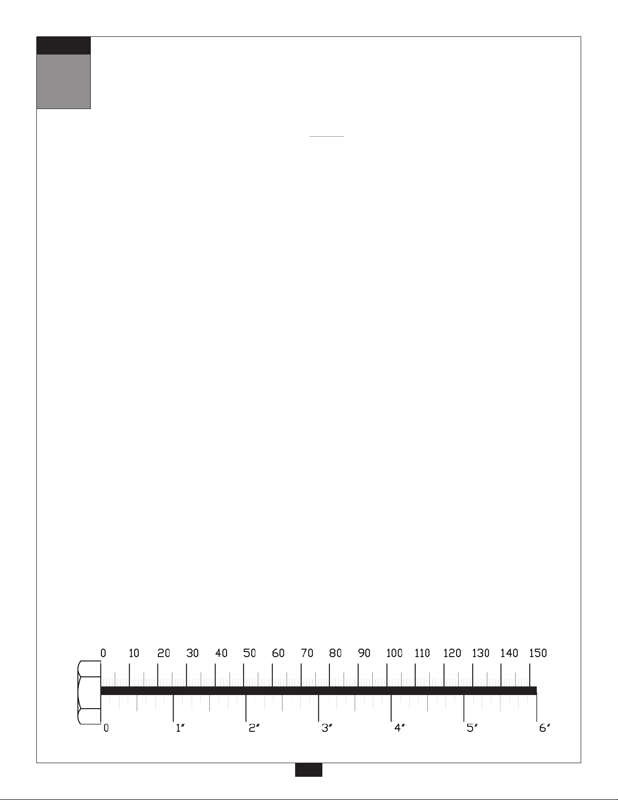
mm
Inch
2
Page 3
STEP
1
3
Page 4
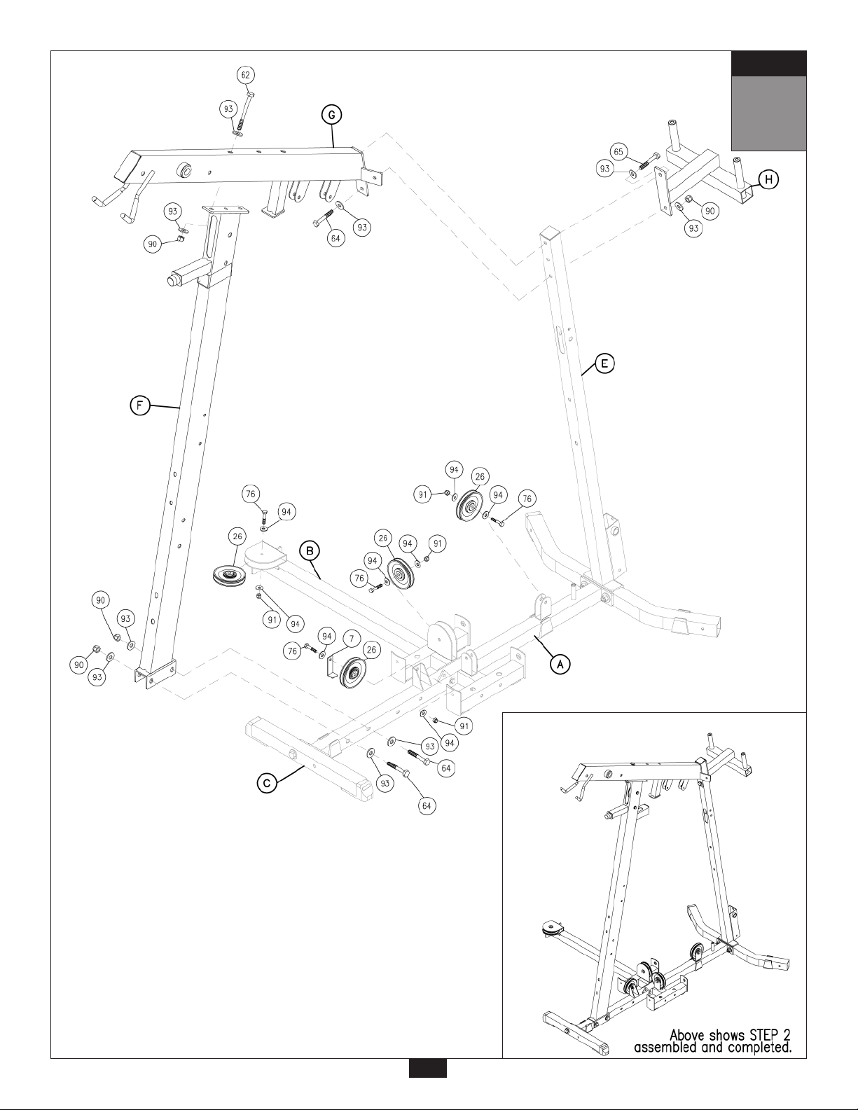
STEP
2
Be careful to assemble all components
in the sequence they are presented.
NOTE:
Finger tighten all hardware in this step. Do Not
A. Attach one Pulley (26) to Main Base Frame (A) and two Pulleys to Side Base Frame (B) as
shown using:
Three 76 (3/8”x 1 3/4” hex head bolt)
Six 94 (3/8” washer)
Three 91 (3/8” nylon lock nut)
B. Attach one Pulley (26) and Pulley Cable Guide (7) to the middle of the Main Base Frame (A)
as shown using
One 76 (3/8”x 1 3/4” hex head bolt)
Two 94 (3/8” washer)
One 91 (3/8” nylon lock nut)
C. Attach Front Vertical Frame (F) to Main Base Frame (A) as shown using:
Two 64 (1/2”x 3 1/4” hex head bolt)
Four 93 (1/2” washer)
Two 90 (1/2” nylon lock nut)
wrench tighten until end of step 5.
D. Attach Top Main Frame (G) to Front Vertical Frame (F) as shown using only one bolt:
One 62 (1/2”x 5” hex head bolt)
Two 93 (1/2” washer)
One 90 (1/2” nylon lock nut)
E. Attach Top Main Frame (G) and Pec Dec Frame (H) to Rear Vertical Frame (E) using:
One 65 (1/2”x 3” hex head bolt)*
One 64 (1/2”x 3 1/4” hex head bolt)
Three 93 (1/2” washer)
One 90 (1/2”nylon lock nut)
*NOTE:
The top bolt (65) goes into an internally threaded nut inside the Top Main Frame (G).
mm
Inch
4
Page 5
STEP
2
5
Page 6
STEP
3
Be careful to assemble all components
in the sequence they are presented.
NOTE:
Finger tighten all hardware in this step. Do Not
A. Place two Weight Stack Risers (55) and two Rubber Donuts (31) onto Main Base Frame (A)
as shown. Slide two Guide Rods (J) through the Rubber Donuts (31), the Weight Stack
Risers (55), and into the Main Base Frame (A).
B. Slide 20 Weight Stack Plates (51) onto the two Guide Rods (J). Make sure the opening in
each weight stack plate, for the Weight Stack Pin (1), is facing outwar
C. Attach Top Plate (8) to Selector Rod (6) using:
One 77 (3/8”x 2” flat allen head)
Slide Top Plate (8) and Selector Rod (6) onto Guide Rods (J).
D. Place two Weight Stack Risers (55) and two Rubber Donuts (31) onto Side Base Frame (B)
as shown. Slide two Guide Rods (J) through the Rubber Donuts (31), the Weight Stack
Risers (55), and into the Side Base Frame (B).
wrench tighten until end of step 5.
d.
E. Slide 20 Weight Stack Plates (51) onto the two Guide Rods (J). Make sure the opening in
each weight stack plate, for the Weight Stack Pin (1), is facing outwar
F. Attach Top Plate (8) to Selector Rod (6) using:
One 77 (3/8”x 2” flat allen head)
Slide Top Plate (8) and Selector Rod (6) onto Guide Rods (J).
G. Slide four Shaft Collars (22) onto the four Guide Rods (J) as shown.*
*NOTE:
Do not tighten the allen screw inside Shaft Collars (22), leave them loose.
≈
d.
mm
Inch
6
Page 7

STEP
3
7
Page 8

STEP
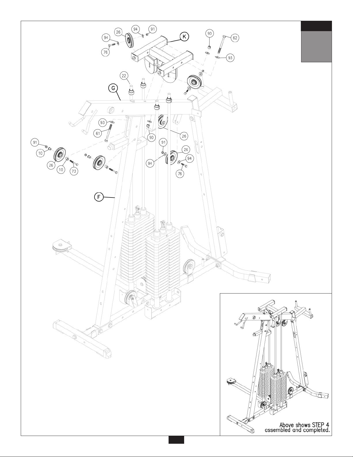
4
Be careful to assemble all components
in the sequence they are presented.
NOTE:
Finger tighten all hardware in this step. Do Not
A. Attach Top Pulley Frame (K) to Top Main Frame (G) and Front Vertical Frame (F) as shown using:
One 61 (1/2”x 5 1/4” hex head bolt)
One 62 (1/2”x 5” hex head bolt)
Four 93 (1/2” washer)
Two 90 (1/2” nylon lock nut)
B. Slide the four Shaft Collars (22) to the top of the four Guide Rods (J).
Insert the top of the Shaft Collars (22) into Top Pulley Frame (K).
Tighten the allen screw in each Shaft Collars (22).
C. Insert two Pulleys (26) into Front Vertical Frame (F) as shown using:
Four 10 (pulley spacer)
Two 73 (3/8”x 2 3/4” hex head bolt)
Two 91 (3/8” nylon lock nut)
wrench tighten until end of step 5.
D. Insert two Pulleys (26) into Top Pulley Frame (K) using:
Two 76 (3/8”x 1 3/4” hex head bolt)
Four 94 (3/8” washer)
Two 91 (3/8” nylon lock nut)
E. Insert two Pulleys (26) into the pulley covers on the Top Main Frame (G) using:
Two 76 (3/8”x 1 3/4” hex head bolt)
Four 94 (3/8” washer)
Two 91 (3/8” nylon lock nut)
mm
Inch
8
Page 9
STEP
4
9
Page 10
STEP
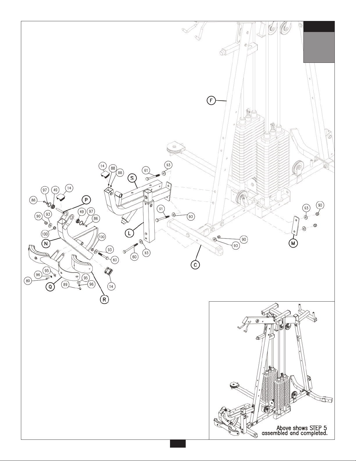
5
Be careful to assemble all components
in the sequence they are presented.
Most of the main frame parts in this step will have RED dots.
NOTE:
LEG EXTENSION SEAT PAD FRAME (S) AND THE LEG EXTENSION FRAME (L) ARE
PRE-ASSEMBLED AS ONE PIECE.
A. Attach Leg Extension Frame (L) and 2”x 6” Plate (M) to Front Vertical Frame (F) using:
Two 61 (1/2”x 5 1/4” hex head bolt)
Four 93 (1/2” washer)
Two 90 (1/2” nylon lock nut)
B. Attach the bottom of Leg Extension Frame (L) to Front Base Frame (C), through the
opening left from step 1 using:
One 60 (1/2”x 5 1/2” hex head bolt)
Two 93 (1/2” washer)
One 90 (1/2” nylon lock nut)
C. Attach Leg Extension Arm (N) to Leg Extension Frame (L) using pre-installed Shaft (P) as
shown. Tighten the two Allen Screws (88) to lock down Shaft (P) in Leg Extension Frame (L).
Attach three End Caps (14) to the top of Leg Extension Frame (L) and each end of the
Leg Extension Arm (N).
D. Attach Leg Extension Pad Holder (Q) to Leg Extension Arm (N) using:
One 63 (1/2”x 3 1/2” hex head bolt)
Two 93 (1/2” washer)
One 90 (1/2” nylon lock nut)
Bronze Bushing (100) was pre-assembled, inside Leg Extension Arm (N).
E. Attach Leg Pads (R) to Leg Extension Pad Holder (Q) using:
Four 89 (5/16”x 3/4” round bolt)*
Four 96 (5/16” spring lock washer)
Four 95 (5/16” washer)
*Do NOT over-tighten these bolts. Tighten these bolts until spring lock washer is flat.
Over - tightening these bolts will cause T - nuts in pads to strip out.
NOTE:
At this point you must make sure that the gym is level, stable and in the right location.
You should now wrench tighten all bolts and nuts on the mainframe unit only.
Do NOT re-tighten any of the pad bolts. Also, leave all pulley bolts finger-tight until
after STEP 20.
mm
Inch
10
Page 11
STEP
5
11
Page 12

STEP
6
Be careful to assemble all components
in the sequence they are presented.
Most of the main frame parts in this step will have RED dots.
A. Attach End Cap (15) onto the front of Leg Extension Seat Pad Frame (S).
B. Insert two Round End Caps (29) into the end of Leg Extension Handles (U). Attach Leg
Extension Handles (U) to Leg Extension Seat Pad Frame (S) using:
Two 72 (3/8”x 3” hex head bolt)
Four 94 (3/8” washer)
Two 91 (3/8” nylon lock nut)
C. Attach Leg Extension Seat Pad (V) to Leg Extension Seat Pad Frame (S) using:
Two 82 (5/16”x 2 3/4” hex head bolt)*
Two 96 (5/16” spring lock washer)
Two 95 (5/16” washer)
*Do NOT over-tighten these bolts. Tighten these bolts until spring lock washer is flat.
Over - tightening these bolts will cause T - nuts in pads to strip out.
D. Slide 4”x 8” Foam Rollers (12) onto Foam Roller Bar (W) and attach to Leg Extension Seat
Pad Frame (S). Hold Foam Rollers (12) in place with 3” Plastic Washer (5) on the inside and
Plastic Roller End Cap (18) on the outside as shown.
Note:
You should now wrench tighten all bolts and nuts in this step.
Do NOT re-tighten any of the pad bolts or pulley bolts.
mm
Inch
12
Page 13

STEP
6
13
Page 14
STEP
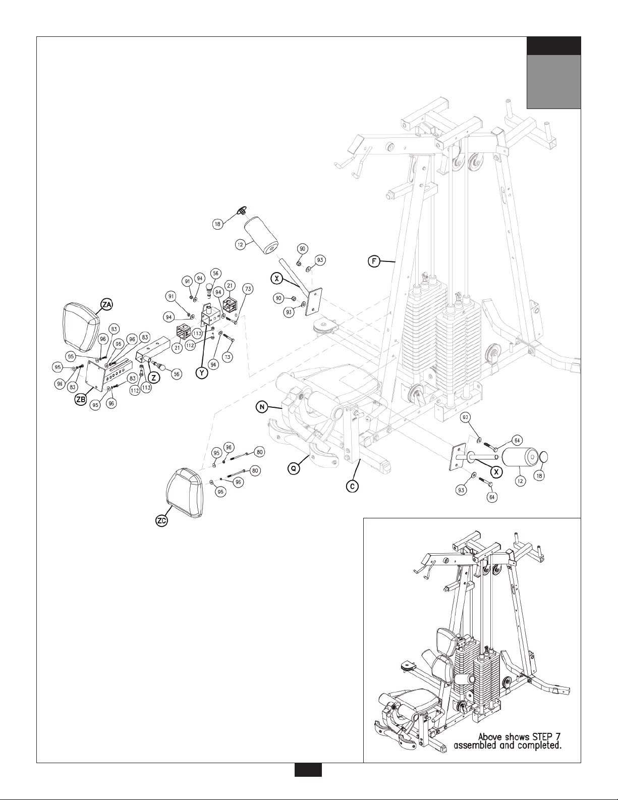
7
Be careful to assemble all components
in the sequence they are presented.
Most of the main frame parts in this step will have RED dots.
A. Attach two Leg Hold Downs (X) to the Front Vertical Frame (F) using:
Two 64 (1/2”x 3 1/4” hex head bolt)
Four 93 (1/2” washer)
Two 90 (1/2” nylon lock nut)
Slide two 4”x 8” Foam Rollers (12) onto the two Leg Hold Downs (X) and hold in place with
two Plastic Roller End Caps (18).
B. Insert two Plastic Bushings (21) into the Back Pad Holder (Y). Connect Back pad Holder (Y)
to the Front Vertical Frame (F) using:
Two 73 (3/8”x 2 3/4” hex head bolt)
Four 94 (3/8” washer)
Two 91 (3/8” nylon lock nut)
C. Slide Back Pad Adjuster (Z) into the Back Pad Holder (Y) and hold in place with Ball Head
Pop Pin (56) and Adjustment Bolt (112). Look inside Back Pad Adjuster (Z) and adjust the
Adjustment Bolt (112) with Lock Nut (113) so that it will stop Back Pad Adjuster (Z) from
sliding out, but will not interfere with Back Pad Insert (ZB) in the next step.
D. Attach Upper Back Pad (ZA) to Back Pad Insert (ZB) using:
Four 83 (5/16”x 1” hex head bolt)*
Four 96 (5/16” spring lock washer)
Four 95 (5/16” washer)
*Do NOT over-tighten these bolts. Tighten these bolts until spring lock washer is flat.
Over - tightening these bolts will cause T - nuts in pads to strip out.
Slide Back Pad Insert (ZB) into Back Pad Adjuster (Z) and hold in place with Ball Head
Pop Pin (56) and Adjustment Bolt (112).
E. Attach Lower Back Pad (ZC) to Front Vertical Frame (F) using:
Two 80 (5/16”x 5” hex head bolt)*
Two 96 (5/16” spring lock washer)
Two 95 (5/16” washer)
*Do NOT over-tighten these bolts. Tighten these bolts until spring lock washer is flat.
Over - tightening these bolts will cause T - nuts in pads to strip out.
Note:
You should now wrench tighten all bolts and nuts in this step.
Do NOT re-tighten any of the pad bolts or pulley bolts.
mm
Inch
14
Page 15
STEP
7
15
Page 16

STEP
8
Be careful to assemble all components
in the sequence they are presented.
Most of the main frame parts in this step will have RED dots.
NOTE:
You will need to loosen two Allen Screws (88) inside Seated Press Arm
Support (AA), in order to remove shaft (AB).
A. Attach Seated Press Arm Support (AA) to Top Main Frame (G) with Shaft (AB).
Tighten Allen Screw (88) in Seated Press Arm Support (AA).
B. Attach two Pulleys (26) to Seated Press Arm Support (AA) using:
Two 76 (3/8”x 1 3/4” hex head bolt)
Four 94 (3/8” washer)
Two 91 (3/8” nylon lock nut)
NOTE:
You will need to loosen two Allen Screws (88), inside Seated Press Arm (AC), in
order to remove shaft (AD).
C. Attach Seated Press Arm (AC) to Seated Press Arm Support (AA) with Shaft (AD).
Tighten two Allen Screws (88) in Seated Press Arm Support (AA) and in Seated
Press Arm (AC).
D. Attach two End Caps (14) to the top of Seated Press Arm Support (AA).
Attach two End Caps (15) to the top of Seated Press Arm (AC).
E. Attach Small Shroud (AE) to Seated Press Arm Support (AA) using:
Four 86 (5/16” x 9/16” round allen head)
Four 97 ( 5/16” washer)
Note:
You should now wrench tighten all bolts and nuts in this step.
Do NOT re-tighten any of the pad bolts or pulley bolts.
mm
Inch
16
Page 17

STEP
8
17
Page 18

STEP
9
Be careful to assemble all components
in the sequence they are presented.
Most of the main frame parts in this step will have
YELLOW dots.
A. Attach three End Caps (13) to the front and sides of Pec Dec Frame (H), and attach Square
Rubber Cap (32) to the top of the Pec Dec Frame (H).
B. Slide Oilite Washer (9), Left Pec Dec Arm (AK) and then the Left Pec Dec Cam (AL) onto
the left side of the Pec Dec Frame (H) as shown, Attach using:
One 59 (1/2”x 1” hex head bolt)
One 93 (1/2” washer)
C. Slide Round End Cap (29) into Left Pec Dec Handle (AM) and attach to the
Left Pec Dec Arm (AK) using:
One 85 (5/16”x 3/4” flat allen head)
One 96 (5/16” spring lock washer)
Note:
Left Pec Dec Handle (AM) should bend out, away from the the gym, as shown.
D. Slide Oilite Washer (9), Right Pec Dec Arm (AP) and then the Right Pec Dec Cam (AQ)
onto the Right side of the Pec Dec Frame (H) as shown, attach using:
One 59 (1/2”x 1” hex head bolt)
One 93 (1/2” washer)
E. Slide Round End Cap (29) into Right Pec Dec Handle (AR) and attach to the
Right Pec Dec Arm (AP) using:
One 85 (5/16”x 3/4” flat allen head)
One 96 (5/16” spring lock washer)
Note:
Right Pec Dec Handle (AR) should bend out, away from the gym, as shown.
F. Attach two Chrome Collars (106) to the top of Left Pec Dec Handle (AM) and Right Pec
Dec Handle (AR) using:
Two 88 (5/16” allen screw) preinstalled
You should now wrench tighten all bolts and nuts in this step.
Do NOT re-tighten any of the pad bolts or pulley bolts.
mm
Inch
18
Page 19

STEP
9
19
Page 20

STEP
10
Be careful to assemble all components
in the sequence they are presented.
Most of the main frame parts in this step will have
YELLOW dots.
A. Slide Plastic Bushing (23) into the receptacle at the bottom of the Rear Vertical Frame (E)
as shown. Attach Hydraulic Seat Adjuster (AU) to the inside of the receptacle at the bottom
of the Rear Vertical Frame (E) using:
One 72 (3/8”x 3” hex head bolt)
Two 94 (3/8” washer)
One 91 (3/8” nylon lock nut)
B. Attach two End Caps (13) to the front and back of Seat Pad Frame (AV).
Slide Seat Pad Frame (AV) into receptacle at the bottom of Rear Vertical Frame (E), and
attach to the top of Hydraulic Seat Adjuster (AU) using:
One 74 (3/8”x 2 1/2”hex head bolt)
Two 94 (3/8” washer)
One 91 (3/8” nylon lock nut)
Insert Pop Pin (48) into the threaded opening in the receptacle at the bottom of the
Rear Vertical Frame (E).
C. Attach Seat Pad (AW) to Seat Pad Frame (AV) using:
Two 82 (5/16”x 2 3/4” hex head bolt)*
Two 96 (5/16” spring lock washer)
Two 95 (5/16” washer)
*Do NOT over-tighten these bolts. Tighten these bolts until spring lock washer is flat.
Over - tightening these bolts will cause T - nuts in pads to strip out.
D. Attach Back Pad (AX) to Rear Vertical Frame (E) using:
Two 82 (5/16”x 2 3/4” hex head bolt)*
Two 96 (5/16” spring lock washer)
Two 95 (5/16” washer)
*Do NOT over-tighten these bolts. Tighten these bolts until spring lock washer is flat.
Over - tightening these bolts will cause T - nuts in pads to strip out.
Note:
You should now wrench tighten all bolts and nuts in this step.
Do NOT re-tighten any of the pad bolts or pulley bolts.
mm
Inch
20
Page 21

STEP
10
21
Page 22

STEP
11
Be careful to assemble all components
in the sequence they are presented.
A. Attach two End Caps (13) to the ends of the Low Pulley Frame (AY). Connect Low Pulley
Frame (AY) to the Main Base Frame (A) using:
One 98 (3/8” washer)
One 87 (3/8” x 5/8” round allen head)
B. Attach Foot Brace (AZ) to the open side of Rear Base Frame (D) using:
One 73 (3/8”x 2 3/4” hex head bolt)
Two 94 (3/8” washer)
One 91 (3/8” nylon lock nut)
C. Attach two End Caps (16) and Grip Tape (33) to Foot Brace (AZ) as shown.
D. Attach Pulley (26) to Low Pulley Frame (AY) using:
One 76 (3/8”x 1 3/4” hex head bolt)
Two 94 (3/8” washer)
One 91(3/8” nylon lock nut)
Note:
You should now wrench tighten all bolts and nuts in this step.
Do NOT re-tighten any of the pad bolts or pulley bolts.
mm
Inch
22
Page 23

STEP
11
23
Page 24

STEP
12
Be careful to assemble all components
in the sequence they are presented.
Most of the main frame parts in this step will have BLUE dots.
A. Attach Leg Press Support (BA) to Main Base Frame (A) using:
Two 73 (3/8”x 2 3/4” hex head bolt)
Four 94 (3/8” washer)
Two 91 (3/8” nylon lock nut)
B. Attach Leg Press Main Frame (BB) to Leg Press Support (BA) using:
Four 73 (3/8”x 2 3/4” hex head bolt)
Eight 94 (3/8” washer)
Four 91 (3/8” nylon lock nut)
C. Attach Leg Press Main Frame (BB) to Side Base Frame (B) using:
Two 73 (3/8”x 2 3/4” hex head bolt)
Four 94 (3/8” washer)
Two 91 (3/8” nylon lock nut)
D. Attach End Cap (15) to the top of Leg Press Main Frame (BB).
Attach two Frame Levelers (25) to the bottom of Leg Press Main Frame (BB).
Attach Pulley (26) to Leg Press Main Frame (BB) using:
One 76 (3/8”x 1 3/4” hex head bolt)
Two 94 (3/8” washer)
One 91 (3/8” nylon lock nut)
E. Attach two Foot Caps (20) to each end of the Leg Press Front (BC).
Attach Leg Press Front (BC) to the front of Leg Press Main Frame (BB) using:
Two 65 (1/2”x 3” hex head bolt)
Four 93 (1/2” washer)
Two 90 (1/2” nylon lock nut)
Note:
You should now wrench tighten all bolts and nuts in this step.
Do NOT re-tighten any of the pad bolts or pulley bolts.
mm
Inch
24
Page 25

STEP
12
25
Page 26

STEP
13
Be careful to assemble all components
in the sequence they are presented.
Most of the main frame parts in this step will have BLUE dots.
A. Slide two Pillow Block Bearings (45) onto lower shaft on Main Leg Press Pivot (BD) and leave
allen screws loose.
NOTE:
Allen screws should both be on the inside.
B. Attach two Pillow Block Bearings (45) to the plate at the front of Leg Press Frame (BB)
using:
Four 66 (1/2”x 1 3/4” hex head bolt)
Eight 93 (1/2” Washer)
Four 90 (1/2” nylon lock nut)
C. Attach Front Leg Press Pivot (BE) and Shaft (BF) to Leg Press Frame (BB)
as shown using:
Two 41 (leg press oilite bushing)
Two 90 (1/2” nylon lock nut)
D. Attach Foot Plate T-frame (BG) and Shaft (BF) to Front Leg Press Pivot (BE)
as shown using:
Two 41 (leg press oilite bushing)
Two 90 (1/2” nylon lock nut)
E. Attach Foot Plate T-frame (BG) and Shaft (BF) to Main Leg Press Pivot (BD)
as shown using:
Two 41 (leg press oilite bushing)
Two 90 (1/2” nylon lock nut)
F. Attach Foot Plate (BR) to Foot Plate T-frame (BG) using:
Two 64 (1/2”x 3 1/4” hex head bolt)
Four 93 (1/2” washer)
Two 90 (1/2” nylon lock nut)
Attach three End Caps (14) to each side of Foot Plate (BR) and front of
Foot Plate T-frame (BG).
Note:
You should now wrench tighten all bolts and nuts in this step.
Do NOT re-tighten any of the pad bolts or pulley bolts.
mm
Inch
26
Page 27

STEP
13
There are two small allen set screws
in each Pillow Block Bearings (45).
For best alignment of this system
you should loosen all
before installing the Pillow Block Bearings (45).
The last and final step of the
assembly process is to
wrench tighten all of these allen
set screws in all the Pillow Block Bearings (45).
allen set screws
27
Page 28

STEP
14
Be careful to assemble all components
in the sequence they are presented.
Most of the main frame parts in this step will have BLUE dots.
A. Slide Round End Cap (29) onto Leg Press Handles (BH).
Attach Leg Press Handles (BH) onto Leg Press Frame (BB) using:
Two 71 (3/8”x 3 1/4” hex head bolt)
Four 94 (3/8” washer)
Two 91 (3/8” nylon lock nut)
B. Attach two Seat Pad Flange (BL) to Leg Press Frame (BB) using:
One 70 (3/8”x 3 1/2” hex head bolt)
Two 94 (3/8” washer)
One 91 (3/8” nylon lock nut)
C. Attach Leg Press Seat Pad (BM) to the two Seat Pad Flange (BL) using:
Two 83 (5/16”x 1” hex head bolt)*
Two 96 (5/16” spring lock washer)
Two 95 (5/16” washer)
*Do NOT over-tighten these bolts. Tighten these bolts until spring lock washer is flat.
Over - tightening these bolts will cause T - nuts in pads to strip out.
D. Attach Leg Press Seat Pad (BM) to Leg Press Frame (BB) using:
One 81 (5/16”x 3 1/4” hex head bolt)*
One 96 (5/16” spring lock washer)
One 95 (5/16” washer)
*Do NOT over-tighten this bolt. Tighten this bolt until spring lock washer is flat.
Over - tightening this bolt will cause T - nut in pad to strip out.
E. Slide Plastic Bushing (23) into Leg Press Frame (BB).
Slide Leg Press Back Pad Frame (BP) into Plastic Bushing (23) and hold in place with
T-Shaped Pop Pin (48).
Attach End Cap (14) to the bottom of Leg Press Back Pad Frame (BP).
F. Attach Leg Press Back Pad (BQ) to Leg Press Back Pad Frame (BP) using:
Four 83 (5/16”x 1” hex head bolt)*
Four 96 (5/16” spring lock washer)
Four 95 (5/16” washer)
*Do NOT over-tighten these bolts. Tighten these bolts until spring lock washer is flat.
Over - tightening these bolts will cause T - nuts in pads to strip out.
Note:
You should now wrench tighten all bolts and nuts in this step.
Do NOT re-tighten any of the pad bolts or pulley bolts.
mm
Inch
28
Page 29

STEP
14
29
Page 30

STEP
15
Be careful to assemble all components
in the sequence they are presented.
NOTE:
All pulleys are the 4 1/4” diameter Pulleys (26), except where noted.
Lat Pulldown Cable (36)
Ball Stop End
Metal Ball End
3840 mm
A. Start at the front of the gym. Insert metal ball end of the Lat Pulldown Cable (36) into Top
Main Frame (G), through the frame and out through the second opening. Pull entire length
of Cable (36) all the way through. Install Pulley (A1) into the first opening, and Pulley (A2)
into the second opening. Be sure that Cable (36) rides on top of these pulleys. Install each
pulley using:
One 73 (3/8”x 2 3/4” hex head bolt)
Two 10 (pulley spacer)
One 91 (3/8” nylon lock nut)
B. Remove Pulley (A3), route Cable (36) inside pulley housing as shown, and re-install
Pulley (A3).
C. Remove Pulley (A4), route Cable (36) around Pulley (A4) as shown, and re-install Pulley (A4).
D. Remove Pulley (A5), route Cable (36) inside pulley housing as shown, and reinstall
Pulley (A5).
E. Route Cable (36) over Pulley (A6). Route Cable (36) down through opening in the small arm
sticking out of the Front Vertical Frame (F). Pull entire length of Cable (36) through.
F. Route Cable (36) through the Double Pulley Holder (130) as shown and install Pulley (A7)
using:
One 76 (3/8”x 1 3/4” hex head bolt)
Two 94 (3/8” washer)
One 91 (3/8” nylon lock nut)
12’ 6”
G. Route Cable (36) up and over Pulley (A8)* and then down toward weight stack.
*Note:
Leave the bolt going through Pulley (A8) hand tight until the end of Cable
Adjustments in Step 21.
H. Remove Bolt (56) from Selector Rod Top Bolt (52), slide Cable (36) through Selector Rod Top
Bolt (52). Attach Cable End Shaft (135) and tighten Allen Screw (136).
Pull Cable (36) tight, so Cable End Shaft (135) fits inside Selector Rod Top Bolt (52).
Reinstall Bolt (56) in Selector Rod Top Bolt (52).
mm
Inch
30
Page 31

Start at high pulley station by
inserting the Metal Ball End here.
STEP
15
Lat Pulldown
Cable
!
Selector Rod Top Bolt (52) must be threaded a
minimum of 1/2” into the Selector Rod (6), and Jam
Nut (54) tightened securely against spring lock
washer (53) to ensure proper connection. Check the
Jam Nut (54) once a week to make sure it is tight.
WARNING
!
31
Page 32

STEP
16
Be careful to assemble all components
in the sequence they are presented.
NOTE:
All pulleys are the 4 1/4” diameter Pulleys (26), except where noted.
Leg Extension Cable (37)
Stamped Eye End
2635mm 8’ 7”
Short Cable (40)
Stamped Eye End
Stamped Eye End
Chain End
520mm
A. Attach either stamped eye end of Leg Extension Cable (37) to Leg Extension Arm (N) using:
One 84 (5/16”x 1 1/2” flat allen head)
Two 4 (3/4” steel bushing)
One 2 (1/2” steel sleeve)
One 92 (5/16” nylon lock nut)
B. Route Cable (37) under Pulley (B1) and up toward Double Pulley Holder (52).
C. Route Cable (37) Inside the bottom portion of Double Pulley Holder (132) as shown, and
install Pulley (B2) using:
One 76 (3/8”x 1 3/4” hex head bolt)
Two 94 (3/8” washer)
One 91 (3/8” nylon lock nut)
D. Attach stamped eye end of Short Cable (40) to Cable (37) using a Snap Link (43). Attach
the chain end of Cable (40) to the Main Base Frame (A) using another Snap Link (43).
1’ 8 1/2”
mm
Inch
32
Page 33

STEP
16
Short Cable
Leg Extension Cable
33
Page 34

STEP
17
Be careful to assemble all components
in the sequence they are presented.
NOTE:
All pulleys are the 4 1/4” diameter Pulleys (26), except where noted.
Pec Dec Cable (38)
Metal Ball End
Metal Ball End
1890mm
A. Attach metal ball end of Pec Dec Cable (38) to Right Pec Dec Cam (AQ) and route under
Top Main Frame (G).
B. Attach the other ball end of Cable (38) to Left Pec Dec Cam (AL).
C. Attach Pulley (C1) to flange on Top Main Frame (G) behind Right Pec Dec Cam (AQ) using:
One 76 (3/8”x 1 3/4” hex head bolt)
One 7 (pulley cable guide)
Two 94 (3/8” washer)
One 91 (3/8” nylon lock nut)
Route Pec Dec Cable (38) over Pulley (C1).
D. Attach Pulley (C2) to flange on Top Main Frame (G) behind Left Pec Dec Cam (AL) using:
One 76 (3/8”x 1 3/4” hex head bolt)
One 7 (pulley cable guide)
Two 94 (3/8” washer)
One 91 (3/8” nylon lock nut)
Route Pec Dec Cable (38) over Pulley (C2).
E. Hang Pec Dec Pulley Holder (131) on Pec Dec Cable (38) as shown and install
Pulley (C3) using:
One 76 (3/8”x 1 3/4” hex head Bolt)
Two 94 (3/8” washer)
One 91 (3/8” nylon lock nut)
6’ 2 1/2”
mm
Inch
34
Page 35

Pec Dec Cable
STEP
17
35
Page 36

STEP
18
Be careful to assemble all components
in the sequence they are presented.
NOTE:
All pulleys are the 4 1/4” diameter Pulleys (26), except where noted.
Ab Crunch Cable (39)
Ball Stop End
Chain End
1545mm
A. Insert chain end of the Ab Crunch Cable (39) into the opening above Back Pad (AX),
and pull entire length through.
NOTE:
You will now need the 3” diameter Pulley (27), for the next step.
B. Insert 3” Pulley (27) into the Rear Vertical Frame (E) under Cable (39) using:
Two 10 (pulley spacer)
One 73 (3/8”x 2 3/4” hex head bolt)
One 91 (3/8” nylon lock nut)
C. Attach chain end of Cable (39) to the bottom of Pec Dec Pulley Holder (131).
D. Hang Pulley (D2) from on Cable (39) as shown using two Pulley Plates (132) and:
One 76 (3/8”x 1 3/4” hex head bolt)
Two 94 (3/8” washer)
One 91 (3/8” nylon lock nut)
5’ 1”
mm
Inch
36
Page 37

STEP
18
Ab Crunch Cable
37
Page 38

STEP
19
Be careful to assemble all components
in the sequence they are presented.
NOTE:
All pulleys are the 4 1/4” diameter Pulleys (26), except where noted.
Low Pulley Cable (35)
Ball Stop End
4060mm 13’ 3 1/2”
A. Insert metal ball end of Low Pulley Cable (35) at Low Pulley Frame (AY). Insert metal ball end
of Cable (35) under
B. Route Cable (35) over
using:
One 76 (3/8”x 1 3/4” hex head bolt)
Two 94 (3/8” washer)
One 91 (3/8” nylon lock nut)
C. Route Cable (35) under Pulley (E3).
D. Route Cable (35) over
E. Route Cable (35) through Pulley Holder With Hook (133) as shown. Install Pulley (E6) using:
One 76 (3/8”x 1 3/4” hex head bolt)
Two 94 (3/8” washer)
One 91 (3/8” nylon lock nut)
F. Remove Pulley (E7) from pulley housing. Insert Cable (35) into pulley housing as shown and
reinstall Pulley (E7).*
Pulley (E1).
Pulley (E2), and attach Pulley (E2) to the bottom of Pulley Plates (132)
Pulleys (E4) and (E5).
Metal Ball End
*Note:
Leave the bolt going through Pulley (E7) hand tight until the end of Cable
Adjustments in Step 21.
G. Remove Bolt (56) from Selector Rod Top Bolt (52), slide Cable (35) through Selector Rod Top
Bolt (52). Attach Cable End Shaft (135) and tighten Allen Screw (136).
Pull Cable (36) tight, so Cable End Shaft (135) fits inside Selector Rod Top Bolt (52).
Reinstall Bolt (56) in Selector Rod Top Bolt (52).
mm
Inch
38
Page 39

STEP
19
Low Pulley Cable
Low Pulley
Cable
!
Selector Rod Top Bolt (52) must be threaded a
minimum of 1/2” into the Selector Rod (6), and Jam
Nut (54) tightened securely against spring lock
washer (53) to ensure proper connection. Check the
Jam Nut (54) once a week to make sure it is tight.
WARNING
!
39
Page 40

STEP
20
Be careful to assemble all components
in the sequence they are presented.
NOTE:
All pulleys are the 4 1/4” diameter Pulleys (26), except where noted.
Leg Press Cable (34)
Chain EndStamped Eye End
4270mm 14’
A. Attach the chain end of Leg Press Cable (34) to Leg Press Frame (BB) with Snap Link (43).
B. Route Cable (34) into the top of pulley housing in Leg Press Pivot (BD) as shown and
install Pulley (F1) using:
One 75 (3/8”x 2” hex head bolt)
Two 94 (3/8” washer)
One 91 (3/8” nylon lock nut)
C. Route Cable (34) over Pulley (F2) as shown.
D. Route Cable (34) back into the bottom of pulley housing in Leg Press Pivot (BD) and install
Cable (34) over
One 75 (3/8”x 2” hex head bolt)
Two 94 (3/8” washer)
One 91 (3/8” nylon lock nut)
E. Route Cable (34) through the opening in the support column of Leg Press Frame (BB).
Pull entire length of Cable (34) through.
Route Cable (34) around Pulley (F4) as shown and toward Pulley (F5).
F. Route Cable (34) under
Attach Cable (34) to Pulley Holder With Hook (133).
Note:
You should now wrench tighten all bolts and nuts.
Except the pad bolts, Never re-tighten any pad bolts.
Pulley (F3) using:
Pulley (F5) and up to the bottom of Pulley Holder With Hook (133).
mm
Inch
40
Page 41

STEP
20
Leg Press Cable
41
Page 42

STEP
21
NOW IS THE TIME TO MAKE ALL NECESSARY
CABLE ADJUSTMENTS
After cable installation is complete you must check all cables for proper tension. Obvious signs that
cable tension problems exist include:
c Top Plates (8) do not rest directly on the top weight stack plates.
c The holes in the Selector Bar (6) do not line up with the holes in the Weight Stack Plates.
c Cable(s) are sloppy and there is no resistance from the weight stack for the first few
inches of the exercise.
There are TEN areas for cable adjustment on the G9S:
A TWO Selector Rod Top Bolts (52)
B THREE Rubber Stops (42)
C THREE Adjustable Chains on cables (34), (39), (40).
D TWO Adjustments in pulley housing on Top Pulley Frame (K)
SEE NOTE 1 AND NOTE 2 ON PAGE 43.
If there is too much tension, and the Top Plate (8) is not resting directly on the top weight stack plate:
1st.- Turn and tighten the Rubber Stop (B).
2nd.- Move Snap Link (C) to add a link.
3rd.- Move pulley down to a lower hole in pulley housing on Top Pulley Frame (K).
If there is to much play or excessive slack:
1st.- Turn and loosen the Rubber Stop (B).
2nd.- Move Snap Link (C) to minus a link.
3rd.- Move Pulley up to a higher hole in pulley housing on Top Pulley Frame (K).
4th.- Screw the Selector Bar Top Bolt (52) farther into the Selector Bar (6) of the Weight Stack.
NOTE:
Cables should be inspected daily and adjusted periodically to ensure safe and
smooth operation.
NOTE:
After cable adjustment is complete, go back and tighten two bolts in pulley
housing on Top Pulley Frame (K).
mm
Inch
42
Page 43

B. Rubber Stop (42)
Tighten
NOTE 1
Before beginning final cable
adjustments, be sure that both of
these pulley housings butt-up as
close as possible to the welded
stops on the frame pieces.
STEP
21
Selector Rod Top Bolt
Lock Nut
! !
WARNING
Selector Rod Top Bolt (52) Must be threaded a
minimum of a 1/2” into the Selector Rod(6), and
Lock Nut (54) tightened securely to ensure
proper connection.
43
NOTE 2
Check lock nut
weekly to be
sure it is tight
and locked on
to the Selector
Rod.
Page 44

STEP
22
Be careful to assemble all components
in the sequence they are presented.
SEE NOTE 1on page 45:
A. Apply weight stack numbers to weight stack Top Plate (8) and each Weight Stack Plate
as shown.
SEE NOTE 2 on page 45: Note the shape of each shroud for proper placement.
B. Weight Stack Shroud (CA) is pre-assembled with Shroud Insert (CB).
Attach Weight Stack Shroud (CA) to the side of the weight stack as shown.
Bolt onto Side Base Frame (B) and Top Pulley Frame (K) using:
Two 87 (3/8” x 5/8” round allen head)
Two 98 (3/8” washer)
C. Attach Weight Stack Shroud (CC) to the other side of this weight stack using:
Two 87 (3/8” x 5/8” round allen head)
Two 98 (3/8” washer)
D. Weight Stack Shroud (CD) is pre-assembled with Shroud Insert (CE).
Attach Weight Stack Shroud (CD) to the side of the weight stack as shown.
Bolt onto Main Base Frame (A) and Top Pulley Frame (K) Using:
Two 87 (3/8” x 5/8” round allen head)
Two 98 (3/8” washer)
E. Attach Weight Stack Shroud (CF) to the other side of this weight stack using:
Two 87 (3/8” x 5/8” round allen head)
Two 98 (3/8” washer)
mm
Inch
44
Page 45

NOTE 1
Apply weight stack numbers to the Weight
Stack Plates (51). Start at the Top Plate (8) with
the number 1, and the first plate should be
number 2. The following Weight Stack Plates
(51) should be numbered in sequential order
down through the stack.
STEP
2” flat side3/4” flat side
22
3/4” flat side
NOTE 2
This is the top view of the four Weight Stack Shrouds. Note the
shape of each shroud for proper placement.
45
Page 46

G9S Parts List
KEY# QTY PART# DESCRIPTION
A
B
C
D
E
F
G
H
J
K
L
M
N
P
Q
S
T
U
W
X
Y
Z
ZB
AA
AB
AC
AD
AK
AL
AM
AP
AQ
AR
AU
AV
AY
AZ
1
1
1
1
1
1
1
1
4
1
1
1
1
1
1
1
1
2
1
2
1
1
1
1
1
1
1
1
1
1
1
1
1
1
1
1
1
JG9SMBF-A
JG9SSBF-B
JG9SFBF-C
JG9SRBF-D
JG9SRVF-E
JG9SFVF-F
JG9STMF-G
JG9SPDF-H
JG9SGR-J
JG9STPF-K
JG9SLEF-L
JG9SP-M
JG9SLEA-N
JG9SS-P
JG9SLEPH-Q
JG9SLESPF-S
JG9SHSA-T
JG9SLEH-U
JG9SFRB-W
JG9SLHD-X
JG9SBPH-Y
JG9SBPA-Z
JG9SBPI-ZB
JG9SSPAS-AA
JG9SS-AB
JG9SSPA-AC
JG9SS-AD
JG9SLPDA-AK
JG9SLPDC-AL
JG9SLPDH-AM
JG9SRPDA-AP
JG9SRPDC-AQ
JG9SRPDH-AR
JG9SHSA-AU
JG9SPDSF-AV
JG9SLRF-AY
JG9SFB-AZ
MAIN BASE FRAME
SIDE BASE FRAME
FRONT BASE FRAME
REAR BASE FRAME
REAR VERTICAL FRAME
FRONT VERTICAL FRAME
TOP MAIN FRAME
PEC DEC FRAME
GUIDE ROD
TOP PULLEY FRAME
LEG EXTENSION FRAME
2”X 6” PLATE
LEG EXTENSION ARM
2” SHAFT
LEG EXTENSION PAD HOLDER
LEG EXTENSION SEAT PAD FRAME
HYDRAULIC SEAT ADJUSTER (PRE-INSTALLED)
LEG EXTENSION HANDLES
FOAM ROLLER BAR
LEG HOLD DOWN
BACK PAD HOLDER
BACK PAD ADJUSTER
BACK PAD INSERT
SEATED PRESS ARM SUPPORT
9” SHAFT
SEATED PRESS ARMS
11 3/4” SHAFT
LEFT PEC DEC ARM
LEFT PEC DEC CAM
LEFT PEC DEC HANDLE
RIGHT PEC DEC ARM
RIGHT PEC DEC CAM
RIGHT PEC DEC HANDLE
HYDRAULIC SEAT ADJUSTER
PEC DEC SEAT FRAME
LOW PULLEY FRAME
FOOT BRACE
Part numbers are required when ordering parts.
46
Page 47

G9S Parts List
KEY# QTY PART# DESCRIPTION
(continued)
BA
BB
BC
BD
BE
BF
BG
BH
BL
BP
BR
1
1
1
1
1
3
1
2
2
1
1
JG9SLPC-BA
JGPSLPF-BB
JG9SLPF-BC
JG9SLPP-BD
JG9SFLPP-BE
JG9SS-BF
JG9SFPTF-BG
JG9SLPH-BH
JG9SSPF-BL
JG9SLPBF-BP
JG9SFP-BR
LEG PRESS CONNECTION
LEG PRESS FRAME
LEG PRESS FRONT
LEG PRESS PIVOT
FRONT LEG PRESS PIVOT
3” SHAFT
FOOT PLATE T-FRAME
LEG PRESS HANDLES
SEAT PAD FLANGE
LEG PRESS BACK PAD FRAME
FOOT PLATE
Shroud List
KEY# QTY PART# DESCRIPTION
AE
CA
CB
CC
CD
CE
CF
1
1
1
1
1
1
1
JG9SSPHS-AE
JG9SWSS-CA
JG9SSI-CB
JG9SWSS-CC
JG9SWSS-CD
JG9SSI-CE
JG9SWSS-CF
SEATED PRESS HINGE SHROUD
WEIGHT STACK SHROUD
SHROUD INSERT
WEIGHT STACK SHROUD
WEIGHT STACK SHROUD
SHROUD INSERT
WEIGHT STACK SHROUD
Pads List
KEY# QTY PART# DESCRIPTION
R
V
ZA
ZC
AW
AX
BM
BQ
2
1
1
1
1
1
1
1
JG9SLP-R
JG9SLESP-V
JG9SUBP-ZA
JG9SLBP-ZC
JG9SPDSP-AW
JG9SPDBP-AX
JG9SLPSP-BM
JG9SLPBP-BQ
LEG PAD
LEG EXTENSION SEAT PAD
UPPER BACK PAD
LOWER BACK PAD
PEC DEC SEAT PAD
PEC DEC BACK PAD
LEG PRESS SEAT PAD
LEG PRESS BACK PAD
Part numbers are required when ordering parts.
47
Page 48

G9S Hardware List
KEY# QTY PART# DESCRIPTION
1
2
3
4
5
6
7
8
9
10
12
13
14
15
16
17
18
19
20
21
22
23
24
25
26
27
28
29
30
31
32
33
41
42
43
45
47
48
49
50
51
52
53
54
55
56
57
59
2
1
1
2
2
2
3
2
2
10
4
5
13
4
2
1
4
3
2
2
4
3
2
5
26
1
4
10
2
4
1
2
6
3
7
2
1
3
2
2
40
2
2
2
4
2
1
2
JPIN4.25
JSS.5
JSCH.18
JSB.75X.5
JPW31
JSR20
JPCG31
JTP10
JBW1.37X1
JPS.56X.37
JFOAM48
JPEC22X.56
JPEC22X.75
JPEC12
JPEC24
JFHC.37
JPFREC2.5
JFC221.8
JFC222.5
JPB222
JSC1.37X.75
JPB226.5
JBEC2
JFL22
JPP4.25W.75
JPP3W.62
JWSS22
JREC1.5
JRP2450
JRD2.25
JSRC22
JGT5.5
JBB.87X.37
JRS1.5
JSNAP3
JPBB1LP
JRFPG3700
JTSPP3
JBB.87X.37
JBHPP5.5
JSP10
JSRTB.5
JSLW.5
JLN.5
JWSR4.87
JBHPP313
JBHPP311
JHEX121FTB
WEIGHT STACK PIN 4 1/4”L X 7/16”W
STEEL SLEEVE 1/2” OD X 5/16” ID X 3/4”L
STEEL CHAIN 3/16”
STEEL BUSHING 3/4” OD X 1/2” ID X 5/16”W
PLASTIC WASHER 3” OD X 1” ID
SELECTOR ROD (20 selector holes)
PULLEY CABLE GUIDE 3” L X 1”W
TOP PLATE (10 lbs.)
OILITE WASHER 1 3/8” OD X 1” ID (35mm X 25mm)
PULLEY SPACER 9/16” OD X 3/8” ID X 5/8” L (15mm X 9mm X 17mm)
FOAM ROLLER 4” X 8”
PLASTIC END CAP 2” X 2” (9/16” THICK)
PLASTIC END CAP 2” X 2” (3/4” THICK)
PLASTIC END CAP 1” X 2”
PLASTIC END CAP 2” X 4”
FRAME HOLE CAP 3/8” (round)
PLASTIC ROLLER END CAP 2.5” OD X 1” ID
FOOT CAP 2” X 2” (1.8” THICK)
FOOT CAP 2” X 2” (2.5” THICK)
PLASTIC BUSHING 2” X 2” (2” LONG)
SHAFT COLLAR 1 3/8” OD 3/4 ID 1.5” L
PLASTIC BUSHING 2” X 2” (6 1/2” LONG)
PLASTIC BALL-END CAP 2”
FRAME LEVELER 2”X 2”
PLASTIC PULLEY 4 1/4” X 3/4” WIDE
PLASTIC PULLEY 3” X 5/8” WIDE
WEIGHT STACK SHIMS 2” X 2”
ROUND END CAP 1 1/2”
RUBBER PAD
RUBBER DONUT 2 1/2”
SQUARE RUBBER CAP 2” X 2”
GRIP TAPE 5 1/2” X 3 3/4”
OILITE BUSHING 7/8” OD X 3/8” ID (22mm X 11mm leg press)
RUBBER STOP 1 1/2”
SNAP LINK
PILLOW BLOCK BEARING 1” ID
RUBBER FOOT PLATE GUARD-PREINSTALLED
T-SHAPED POP PIN 3” L
OILITE BUSHING 7/8” OD X 3/8” ID (22mm X 11mm leg extension)
BALL HEAD POP PIN 5.5”L (pec dec)
WEIGHT STACK PLATE 10lbs.
SELECTOR ROD TOP BOLT 1/2” X 2” FULL THREAD
SPRING LOCK WASHER 1/2”
JAM NUT 1/2”
WEIGHT STACK RISERS 4 7/8”L
BALL HEAD POP PIN 3 13/16” L (back support)
BALL HEAD POP PIN 3 11/16” L (seated press)
HEX HEAD BOLT 1/2”X 1” FULL THREAD
Part numbers are required when ordering parts.
48
Page 49

G9S Hardware
KEY# QTY PART# DESCRIPTION
(continued)
60
61
62
63
64
65
66
70
71
72
73
74
75
76
77
78
80
81
82
83
84
85
86
87
88
89
90
91
92
93
94
95
96
97
98
101
102
103
104
105
106
107
108
112
113
114
115
135
136
1
JHEX.5X5.5PTB
3
JHEX.5X5.25PTB
2
JHEX.5X5PTB
1
JHEX.5X3.5PTB
9
JHEX.5X3.25PTB
4
JHEX.5X3PTB
4
JHEX.5X1.75FTB
1
JHEX.37X3.5PTB
2
JHEX.37X3.25PTB
3
JHEX.37X3PTB
18
JHEX.37X2.75PTB
1
JHEX.37X2.5PTB
2
JHEX.37X2PTB
21
JHEX.37X1.75PTB
2
JFAH.37X2FTB
2
JHEX.37X.87FTB
2
JHEX.31X5PTB
1
JHEX.31X3.25PTB
6
JHEX.31X2.75FTB
10
JHEX.31X1FTB
1
JFAH.31X1.5FTB
4
JFAH.31X.75FTB
6
JRAH.31X.56FTB
9
JRAH.37X.62FTB
14
JAS.31X.31FT
4
JRAH.31X.75FTB
21
JNLN.5
50
JNLN.37
1
JNLN.31
43
JWFLT.5
90
JWFLT.37
23
JWFLT.31
23
JWSW.31
4
JWFLT.31
9
JWFLT.37
4
JAS.19X.19
2
JCEC1.37X1
2
JRR1.5X1.25
2
JBB1.75X1
2
JBB.87x.62
2
JCC1.43X1
12
JBB1.75X1
2
JACN.19
2
JHEX.37X1FTB
2
JLN.37
2
JSB1.75X1
2
JRR1.75X1.5
2
JCES
2
JAS
HEX HEAD BOLT 1/2” X 5 1/2” PARTIAL THREAD
HEX HEAD BOLT 1/2” X 5 1/4” PARTIAL THREAD
HEX HEAD BOLT 1/2” X 5” PARTIAL THREAD
HEX HEAD BOLT 1/2” X 3 1/2” PARTIAL THREAD
HEX HEAD BOLT 1/2” X 3 1/4” PARTIAL THREAD
HEX HEAD BOLT 1/2” X 3” PARTIAL THREAD
HEX HEAD BOLT 1/2” X 1 3/4” FULL THREAD
HEX HEAD BOLT 3/8” X 3 1/2” PARTIAL THREAD
HEX HEAD BOLT 3/8” X 3 1/4” PARTIAL THREAD
HEX HEAD BOLT 3/8” X 3” PARTIAL THREAD
HEX HEAD BOLT 3/8” X 2 3/4” PARTIAL THREAD
HEX HEAD BOLT 3/8” X 2 1/2” PARTIAL THREAD
HEX HEAD BOLT 3/8” X 2” PARTIAL THREAD
HEX HEAD BOLT 3/8” X 1 3/4” PARTIAL THREAD
FLAT ALLEN HEAD 3/8” X 2” FULL THREAD
HEX HEAD BOLT 3/8” X 7/8” FULL THREAD
HEX HEAD BOLT 5/16” X 5” PARTIAL THREAD
HEX HEAD BOLT 5/16” X 3 1/4” PARTIAL THREAD
HEX HEAD BOLT 5/16” X 2 3/4” FULL THREAD
HEX HEAD BOLT 5/16” X 1” FULL THREAD
FLAT ALLEN HEAD 5/16” X 1 1/2” FULL THREAD
FLAT ALLEN HEAD 5/16” X 3/4” FULL THREAD
ROUND ALLEN HEAD 5/16” X 9/16” FULL THREAD (8mmX15mm)
ROUND ALLEN HEAD 3/8” X 5/8” FULL THREAD (10mmX16mm)
ALLEN SCREW 5/16” X 5/16” FULL THREAD
ROUND ALLEN HEAD 5/16” X 3/4” FULL THREAD
NYLON LOCK NUT 1/2”
NYLON LOCK NUT 3/8”
NYLON LOCK NUT 5/16”
WASHER 1/2”
WASHER 3/8”
WASHER 5/16”
SPRING LOCK WASHER 5/16”
WASHER 5/16” (8mm shrouds)
WASHER 3/8” (10mm shrouds)
ALLEN SCREW 3/16” X 3/16” -PREINSTALLED
CHROME END CAP 1 3/8”OD X 1”ID X 3/4”L- PREINSTALLED
RETAINING RING 1 1/2” OD X 1 1/4”ID (leg ext)-PREINSTALLED
OILITE BUSHING 1 3/4”OD 1”ID - PREINSTALLED (seated press)
OILITE BUSHING 7/8”OD 5/8”ID - PREINSTALLED (low row)
CHROME COLLAR 1 7/16” OD X 1” ID
OILITE BUSHING 1 3/4”OD 1”ID - PREINSTALLED (pec dec)
ACORN CAP NUT 3/16” ID - PREINSTALLED
HEX HEAD BOLT 3/8” X 1” FULL THREAD (adjustment bolt)
LOCK NUT 3/8”
STEEL BUSHING 1 3/4”OD 1” ID - PREINSTALLED (seated press)
RETAINING RING - 1 3/4”OD 1” ID -PREINSTALLED (seated press)
CABLE END SHAFT 3/4” L
ALLEN SCREW 1/8” X 1/4”(4mm X 8mm)
Part numbers are required when ordering parts.
49
Page 50

Cable List
KEY# QTY PART# DESCRIPTION
34
35
36
37
38
39
40
1
1
1
1
1
1
1
JLPC4270
JLRC4060
JLPC3840
JLEC2635
JPDC1890
JACC1545
JSC520
LEG PRESS CABLE 4270 mm(14’)
LOW PULLEY CABLE 4060 mm(13’ 3 1/2”)
LAT PULLDOWN CABLE 3840 mm(12’ 6”)
LEG EXTENSION CABLE 2635 mm(8’ 7”)
PEC DEC CABLE 1890 mm(6’ 2 1/2”)
AB CRUNCH CABLE 1545 mm(5’ 1”)
SHORT CABLE 520 mm(1’ 8 1/2”)
Pulley Holder List
KEY# QTY PART# DESCRIPTION
130
131
132
133
1
1
2
1
JG9SDPH
JG9SPDPH
JG9SPP
JG9SPHWH
DOUBLE PULLEY HOLDER
PEC DEC PULLEY HOLDER
PULLEY PLATE
PULLEY HOLDER WITH HOOK
Accessories List
KEY# QTY PART# DESCRIPTION
120
121
122
123
124
125
126
127
128
POSTER
PAINT
1
1
1
1
2
2
2
2
4
1
1
JG9SLB
JG9SLRB
JG9SAS
JG9SACH
JFG18
JFG8.37
JFG17.25
JFG24
JFG17
G9SPOSTER
TUP-G
LAT BAR
LOW ROW BAR
ANKLE STRAP
AB CRUNCH HARNESS
FOAM GRIP 1 1/2” OD X 18” L -PREINSTALLED
FOAM GRIP 1 1/2” OD X 8 3/8” L -PREINSTALLED
FOAM GRIP 1 1/2” OD X 17 1/4” L -PREINSTALLED
FOAM GRIP 1 1/2” OD X 24” L -PREINSTALLED
FOAM GRIP 1 1/2” OD X 17” L -PREINSTALLED
WORK OUT POSTER
TOUCH UP PAINT - GRAY
Part numbers are required when ordering parts.
50
Page 51

Obtaining Service
Please retain this Owner’s Manual for future reference. When ordering parts you must use the part number and description
from this Owner’s Manual. Use only Body-Solid replacement parts when servicing this machine. Failure to do so will void
your warranty and could result in personal injury.
For more information about product operation or service, check out the official Body-Solid website at www.bodysolid.com
or contact an authorized Body-Solid dealer or a Body-Solid factory authorized service company or contact Body-Solid
customer service at one of the following:
Toll Free: 1-800-833-1227
Phone: 1-708-427-3555
Fax: 1-708-427-3556
E-mail: service@bodysolid.com
Or write to: Body-Solid, Inc.
Service Department
1900 S. Des Plaines Ave.
Forest Park, IL 60130 USA
Ordering replacement parts
When ordering replacement parts, please have the following information available:
1. Model number: G9S
2. Date of purchase: ________________________________________
3. Name of dealer: ________________________________________
__________________________________________________________
4. Dealer location: ________________________________________
__________________________________________________________
__________________________________________________________
__________________________________________________________
5. Part numbers (see pages 46-51):____________________________
__________________________________________________________
6. Description of part:_________________________________________
__________________________________________________________
__________________________________________________________
51
Page 52

EXPLODED VIEW
DIAGRAM
G9S
52
Page 53

© Copyright 2003. Body-Solid. All rights reserved. Body-Solid reserves the right to change design and specifications when we feel it will improve the product.
Body-Solid machines maintain several patented and patent pending features and designs. All rights reserved on all design patents and utility patents.
53
 Loading...