

Page 1
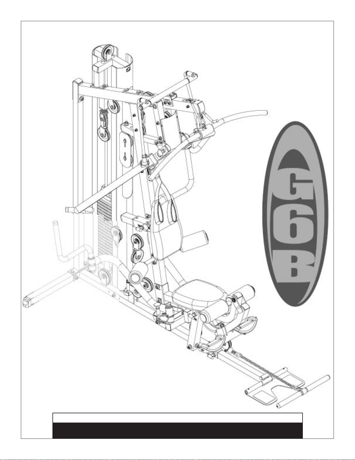
Table of Contents
Total Body Workout DVD . . . . . . . . . . . . . p. 2
Reference Drawings . . . . . . . . . . . . . . . . . p. 3
Safety Instructions . . . . . . . . . . . . . . . . . . p. 4
Before You Begin . . . . . . . . . . . . . . . . . . . p. 5
Dimensions . . . . . . . . . . . . . . . . . . . . . . . . p. 6
Safety Guidelines . . . . . . . . . . . . . . . . . . . p. 7
Preparations . . . . . . . . . . . . . . . . . . . . . . . p. 8
Assembly Instructions . . . . . . . . . . . . p. 9-27
Cable Installations . . . . . . . . . . . . . . p. 28-37
Shroud Installation . . . . . . . . . . . . . . p. 40-41
Cable Adjustments . . . . . . . . . . . . . . p. 38-39
Adjustments . . . . . . . . . . . . . . . . . . . p. 42-45
Warning, Safety & Maintenance . . . . p. 46-47
Maintenance Schedule . . . . . . . . . . .p. 48-49
Phrases, Terms, Tips & Guidelines . . p. 50-51
Nutrition . . . . . . . . . . . . . . . . . . . . . . . . . p. 52
Exercise Prescription . . . . . . . . . . . . . . . p. 53
Training Tips . . . . . . . . . . . . . . . . . . . . . . p. 54
Common Training Mistakes . . . . . . . . . . p. 55
Setting Up Your Personal Program . . . . p. 56
Determine Your Training Method . . . . . . p. 57
Exercise Tips . . . . . . . . . . . . . . . . . . . . . . p. 58
Anatomy Chart . . . . . . . . . . . . . . . . . . . . p. 59
Fitness Goals . . . . . . . . . . . . . . . . . . . . . p. 60
Exercise Logs . . . . . . . . . . . . . . . . . . p. 61-63
Stretching & Flexibility . . . . . . . . . . . . . . p. 64
Stretching: Warm-Up / Cool-Down . p. 65-69
Workout/Exercises . . . . . . . . . . . . . . p. 70-75
Signs of Overtraining . . . . . . . . . . . . . . . p. 76
Weight Ratios . . . . . . . . . . . . . . . . . . . . . p. 77
Obtaining Service . . . . . . . . . . . . . . . . . . p. 79
Mainframe Parts List . . . . . . . . . . . . p. 80-81
Hardware Parts List . . . . . . . . . . . . . p. 82-85
Hardware Diagrams . . . . . . . . . . . . . p. 86-88
Exploded View Diagram . . . . . . . . . . p. 89-90
Body-Solid
®
Assembly Instructions
&
OWNER’S MANUAL
Page 2
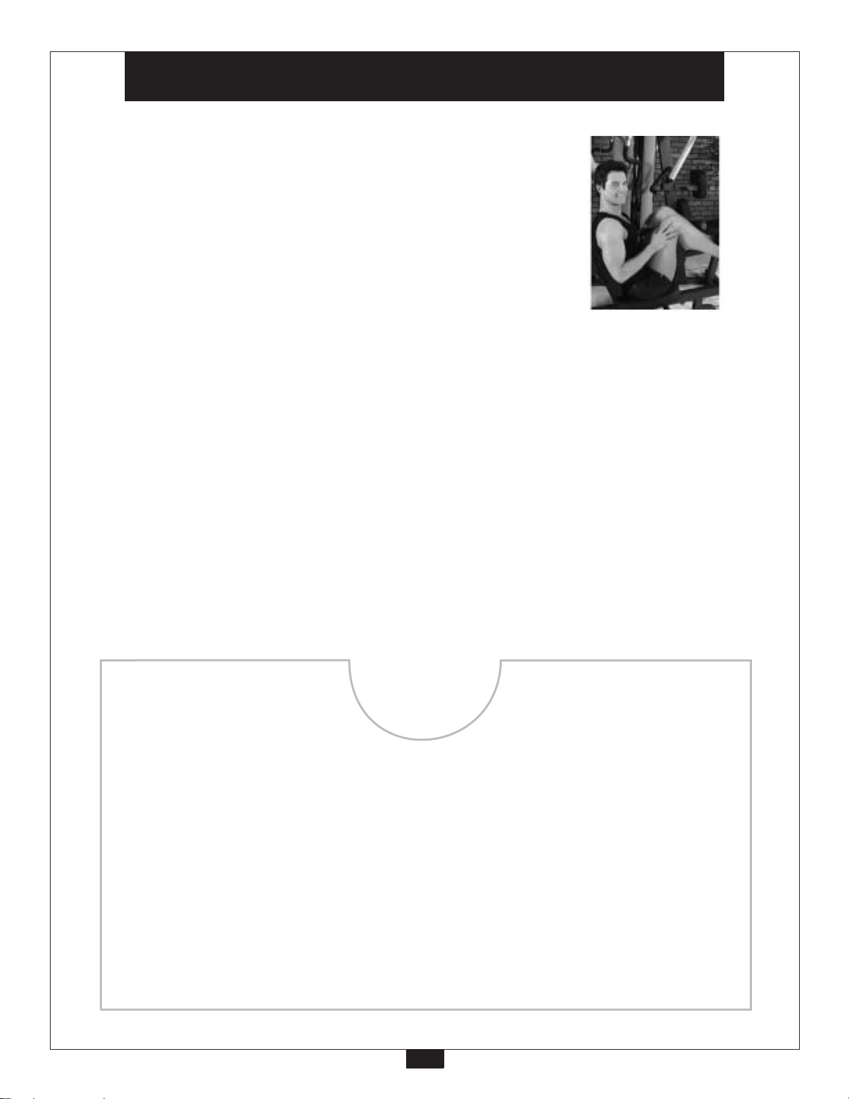
Total Body Workout DVD
Follow the lead of international fitness presenter
Geoff Bagshaw as he guides you step by step through
a total health and conditioning program. Includes
thorough explanations and demonstrations of over 50
exercises targeting all major muscle groups. The
Body-Solid Total Body Workout is a “must have” for
anyone truly serious about in-home training.
Also includes:
l Complete stretching routine
l Importance of cardio training
l Body-Solid company profile
Body-Solid
Total Body Workout DVD
2
Page 3
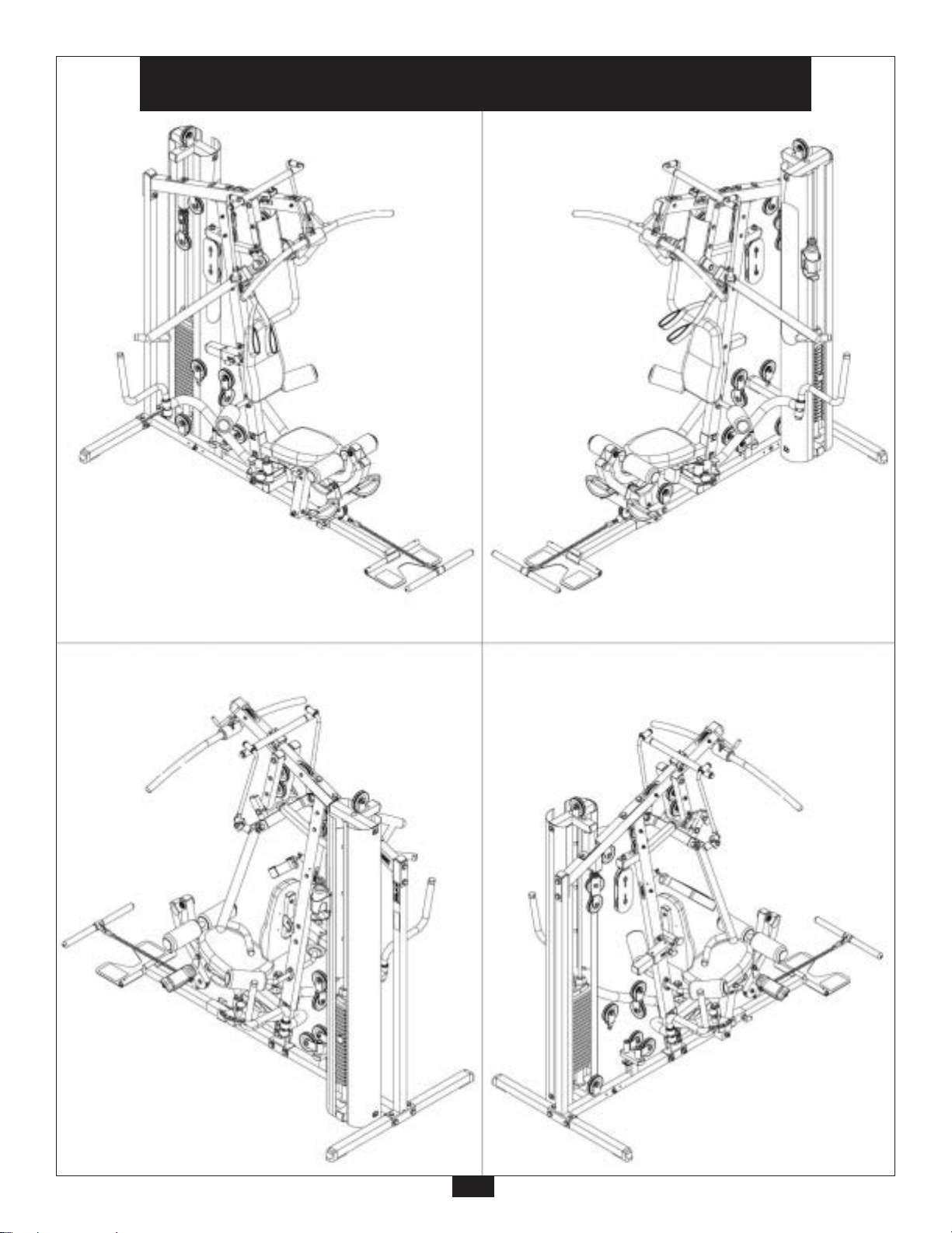
G6B
Reference Drawings
3
Page 4

Important Safety Instructions
Before beginning any fitness program, you should obtain a complete physical examination from your physician.
Il est conseille de subir un examen medical complet avant d’entreprendre tout programme d’exercise.
Si vous avez des etourdissements ou des faiblesses, arretez les exercices immediatement.
Antes de comenzar cualquier pr
When using exercise equipment, you
should always take basic precautions,
including the following:
Read all instructions before using the G6B. These
•
instructions are written to ensure your safety and to
protect the unit.
Do not allow childr
•
Use the equipment only for its intended purpose as
•
described in this guide. Do not use accessory
attachments that are not recommended by the
manufacturer. Such attachments might cause injuries.
Wear proper exercise clothing and shoes for your
•
workout, no loose clothing.
Use care when getting on or off the unit.
•
Do not overexert yourself or work to exhaustion.
•
If you feel any pain or abnormal symptoms, stop your
•
workout immediately and consult your physician.
Never operate unit when it has been dropped or
•
damaged. Return the equipment to a service center
for examination and repair.
Never drop or insert objects into any opening in the
•
equipment.
Always check the unit and its cables before each
•
use. Make sure that all fasteners and cables are
secure and in good working condition.
Do not use the equipment outdoors or near water.
•
Personal Safety During Assembly
It is strongly recommended that a qualified dealer
•
assemble the equipment.
Before beginning assembly, please take the time to
•
read the instructions thoroughly.
Read each step in the assembly instructions and
•
follow the steps in sequence. Do not skip ahead. If
you skip ahead, you may learn later that you have to
disassemble components and that you may have
damaged the equipment.
Assemble and operate the G6B on a solid, level
•
surface. Locate the unit a few feet from the walls or
furniture to provide easy access.
en on or near the equipment.
ogramma de ejercicios, deberias tener un examen fisico con su doctor.
Assistance is required.
The G6B is designed for your enjoyment. By
following these precautions and using common
sense, you will have many safe and pleasurable hours
of healthful exercise with your Body-Solid G6B.
After assembly, you should check all functions to
ensure correct operation. If you experience problems,
first recheck the assembly instructions to locate any
possible errors made during assembly. If you are unable
to correct the problem, call the dealer from whom
you purchased the machine or call 1-800-833-1227
for the dealer nearest you.
Obtaining Service
Please use this Owner’s Manual to make sure that all
par
ts have been included in your shipment. When
ordering parts, you must use the par
description from this Owner’s Manual. Use only
Body-Solid replacement parts when servicing this
machine. Failure to do so will void your warranty and
could result in personal injury.
For information about product operation or service,
check out the official Body-Solid website at
www.bodysolid.com or contact an authorized
Body-Solid dealer or a Body-Solid factory-authorized
service company or contact Body-Solid customer
service at one of the following:
Toll Free: 1-800-556-3113
Phone: 1-708-427-3555 ext. 5
Fax: 1-708-427-3598
E-mail: service@bodysolid.com
Or write to: Body-Solid, Inc.
Retain this Owner’s Manual for future
r
eference. Part numbers ar
ordering parts.
Service Department
1900 S. Des Plaines Ave.
Forest Park, IL 60130 USA
t number and
e required when
4
Page 5

Before You Begin
Thank you for purchasing the G6B. This gym is part of the Body-Solid line of quality strength training
machines, which let you target specific muscle groups to achieve better muscle tone and overall body
conditioning. To maximize your use of the equipment please study this Owner’s Manual thoroughly.
Unpacking the Equipment
The G6B is carefully tested and inspected before
shipment. Body-Solid ships the unit in several pie
that require assembly. Ask for assistance during the
assembly process.
Carefully unpack the boxes and lay the pieces on
the floor near the area where you plan to use the
equipment.
ces
Be careful to assemble all components in the
sequence presented in this guide.
If any items are missing, contact the dealer from whom
you purchased the unit or call 1-800-833-1227 for
the dealer nearest you.
5
Page 6
Dimensions
The room layout diagram below will help you decide the best placement for your G6B.
The dimensions of the G6B are: width 4’ X length 7’1”. The ceiling height requirement for the G6B is 7’.
The usage space is: width 7’ X length 10’ 4” (The usage space is the overall space needed for operation.)
The usage space needed for the G6B could be more, depending on the user, allow enough room for the Low Row Station.
6’ 11.5”
Dimensions
7’ 1”
Height
4’
Suggested usage space
10’ 4”
7’
6
Page 7

Safety Guidelines
Successful resistance training programs have one prominent feature in common...safety. Resistance training
has some inherent dangers, as do all physical activities. The chance of injury can be greatly reduced or
completely removed by using correct lifting techniques, proper breathing, maintaining equipment in good
working condition, and by wearing the appropriate clothing.
1. It is highly recommended that you consult your physician before beginning any exercise program.
This is especially important for individuals over the age of 35, or persons with pre-existing health
problems.
2. Always warm up before starting a workout. Try to do a total body warm up before you start. It is
especially important to warm up the specific muscle groups you are going to be using. This can
be as simple as performing a warm up set of high repetitions and light weight for each exercise.
3. Use proper form. Focus on only working the muscle groups intended for the exercise you are doing.
If there is strain elsewhere, you may need to re-evaluate the amount of weight that is involved with
the lift. Keeping proper form also includes maintaining control through an entire range of motion.
4. Breath properly. Inhale during the eccentric phase of the exercise, and exhale during the lifting, or
concentric phase. Never hold your breath during any part of an exercise.
the entire range of motion.
5. Always wear the appropriate clothing and shoes when exercising. Wearing comfortable athletic shoes
with good support and loose fitting, breathable clothing will reduce the risk of injury.
suitable, breathable clothing will reduce the risk of injury.
6. Maintaining equipment in proper operating condition is of utmost importance for a safe resistance
training program. Pulleys and cables should be checked for wear frequently and replaced as needed.
Equipment should be lubricated as indicated by the manufacturer.
7. Read and study all warning labels on this machine. It is absolutely necessary that you familiarize
yourself and all others with the proper operation of this machine prior to use.
8. Keep hands, limbs, loose clothing and long hair well out of the way of all moving parts.
9. Do not attempt to lift more weight than you can control safely.
10.Inspect the machine daily for loose or worn parts. If a problem is found do not allow the machine to
be used until all parts are tightened or worn or defective parts are repaired or replaced.
7
Page 8

Preparations
CAUTION: To set up this unit, you will need assistance. Do not attempt assembly by yourself.
You must review and follow the instructions in this Owner’s Manual. If you do not assemble and use the G6B
according to these guidelines, you could void the Body-Solid warranty.
Required Tools
The tools that you must obtain before assembling
the G6B include:
c
3mm Allen Key
c
4mm Allen Key
c
5mm Allen Key
c
6mm Allen Key
c
8mm Allen Key
c
9/16” Open-End W
c
11/16” Open-End Wr
c
13/16” Open-End Wrench
c
3/4” Open-End Wrench
c
9/16” Box Wrench
c
11/16” Box Wrench
c
13/16” Box Wrench
c
3/4” Box Wrench
rench
ench
CAUTION: Obtain assistance! Do not attempt to assemble
the G6B by yourself. Review the Installation
Requirements before proceeding with the following
steps.
The G6B unit comes in eight boxes. Be careful to
assemble components in the sequence presented in
this guide.
NOTE: With so many assembled parts, proper alignment
and adjustment is critical. While tightening the nuts
and bolts, be sure to leave room for adjustments.
Installation Requirements
Follow these installation requirements when assembling
the G6B:
Set up the G6B on a solid, flat surface. A s
surface under the machine helps keep it level. A
level machine has fewer malfunctions.
Provide ample space around the machine. Open
space around the machine allows for easier access.
Insert all bolts in the same direction. For aesthetic
purposes, insert all bolts in the same direction unless
specified (in text or illustrations) to do otherwise.
Leave room for adjustments. Tighten fasteners such as
bolts, nuts, and screws so the unit is stable, but leave
room for adjustments. Do not fully tighten fasteners
until instructed in the assembly steps to do so.
Fill out and mail warranty card.
mooth, flat
8
Page 9
Assembly Instructions
Assembly of the G6B takes professional installers about 3 hours to complete. If this is the first time you have
assembled this type of equipment, plan on significantly more time.
Professional installers are highly recommended!
However, if you acquire the appropriate tools, obtain assistance, and follow the assembly steps sequentially,
the process will take time, but is fairly easy.
Assembly Tips
Read all “Notes” on each page before beginning each step.
While you may be able to assemble the G6B using the
illustrations only, important safety notes and other tips are
included in the text.
Some pieces may have extra holes that you will not use. Use
o
nly those holes indicated in the instructions and illustrations.
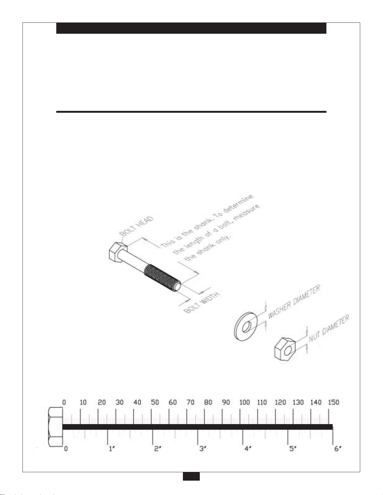
NOTE: To find out the length of a particular bolt, measure its
shank (the long, narrow part beneath the head). Refer to the
following diagram:
IMPORTANT!
Before you begin you should fold-out pages 86, 87 and 88.
This is a quick reference guide that shows all hardwar
parts (in actual size) along with the corresponding key
numbers on the assembly instructions.
e
Do not fully tighten bolts until instructed to do so.
Note: After assembly, you should check all functions
to ensure correct operation. If you experience
problems, first recheck the assembly instructions
to locate any possible errors made during assembly.
If you are unable to correct the problem, call the
dealer from whom you purchased the machine or
call 1-800-833-1227 for the dealer nearest you.
mm
Inch
9
Page 10

STEP
1
Be careful to assemble all components
in the sequence they are presented.
NOTE:
Finger tighten all har
A. Attach Frame Leveler (10) to Main Base Frame (A) as shown.
Insert two Weight Stack Shims (11) to Main Base Frame (A) as shown.
Insert Convex End Cap (28) to the opening in Main Base Frame (A) as shown.
B. Attach Main Base Frame (A) to Rear Base Frame (B) and Rear Vertical Frame (C) using:
Two 40 (1/2” x 3 1/4” hex head bolt)
Four 73 (1/2” washer)
Two 70 (1/2” nylon lock nut)
Also use:
Two 55 (3/8” x 2 3/4” hex head bolt)
T
wo 74 (3/8” washer)
Two 71 (3/8” nylon lock nut)
C. Insert two Foot Caps (6) to the ends of Rear Base Frame (B).
Inser
t Convex End Cap (2) to the top of Rear Vertical Frame (C) as shown.
dware in this step. Do Not
wrench tighten until end of step 3.
mm
Inch
10
Page 11

STEP
1
11
Page 12

STEP
2
Be careful to assemble all components
in the sequence they are presented.
NOTE:
Finger tighten all har
A. Attach Angled Support Frame (D) to Main Base Frame (A) using:
Two 40 (1/2” x 3 1/4” hex head bolt)
Four 73 (1/2” washer)
Two 70 (1/2” nylon lock nut)
dware in this step. Do Not
wrench tighten until end of step 3.
B. Insert Convex End Cap (4) to the fr
Attach T
T
Three 73 (1/2” washer)
One 70 (1/2” nylon lock nut)
*NOTE:
One bolt (40) goes into an internally threaded nut inside T
C. Attach Top Frame (E) and Plate (68) to Angled Support Frame (D) using:
Two 43 (1/2” x 4 1/4” hex head bolt)
Four 73 (1/2” washer)
T
D. Insert Convex End Cap (2) to the small horizontal ar
op Frame (E) and Plate (67) to the Rear Vertical Frame (C) using:
wo 40 (1/2” x 3 1/4” hex head bolt)*
wo 70 (1/2” nylon lock nut)
ont of the Top Frame (E).
op Frame (E).
m on Angled Support Frame (D) as shown.
mm
Inch
12
Page 13
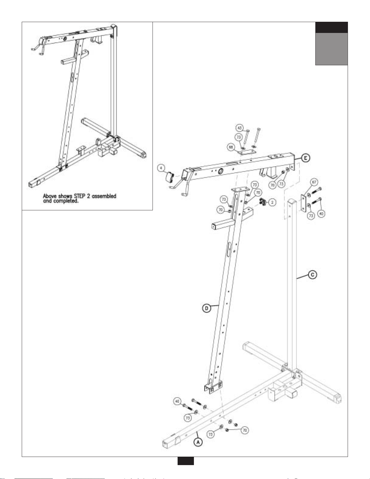
STEP
2
13
Page 14

STEP
3
Be careful to assemble all components
in the sequence they are presented.
NOTE:
At this point you must make sure that the gym is level, stable and in the right location.
A. Place two Weight Stack Risers (36) and two Rubber Donuts (14) onto Main Base Frame (A) as
shown. Slide two Guide Rods (F) through the Rubber Donuts (14), through the two Weight
Stack Risers (36), and into the Main Base Frame (A).
B.
*NOTE:
Use fifteen 10lb. plates for a 160lb. weight stack.
Use twenty 10lb. plates for a 210lb. weight stack. See NOTE after Step 1B.
C. Connect Top Plate (17) to the Selector Rod (19) using:
D.
E. Insert Guide Rods (F) into T
F
. Slide Shaft Collars (7) up into the Top W
G. You can now wrench tighten all bolts and nuts on the main frame unit.
Slide Weight Stack Plates (37)* onto Guide Rods (F). Make sure the opening in each Weight
Stack Plate (37), for the Weight Stack Pin (81), is facing outwar
One 58 (3/8” x 2” round allen head)
One 134 (3/8” spring lock washer)
Slide Top Plate (17) and Selector Rod (19) onto Guide Rods (F).
Slide two Shaft Collars (7) onto the two Guide Rods (F) as shown.
op Weight Stack Frame (G), and Attach Top Weight Stack
Frame (G) to Top Frame (E) using:
Two 50 (3/8” x 1” hex head bolt)
T
wo 74 (3/8” washer)
Attach Convex End Cap (2) to Top Weight Stack Frame (G) as shown.
eight Stack Frame (G) and turn the Shaft Collar, so it
locks onto the Top Weight Stack Frame (G), Now tighten each Allen Screw (32) in Shaft Collars (7).
d.
mm
Inch
14
Page 15
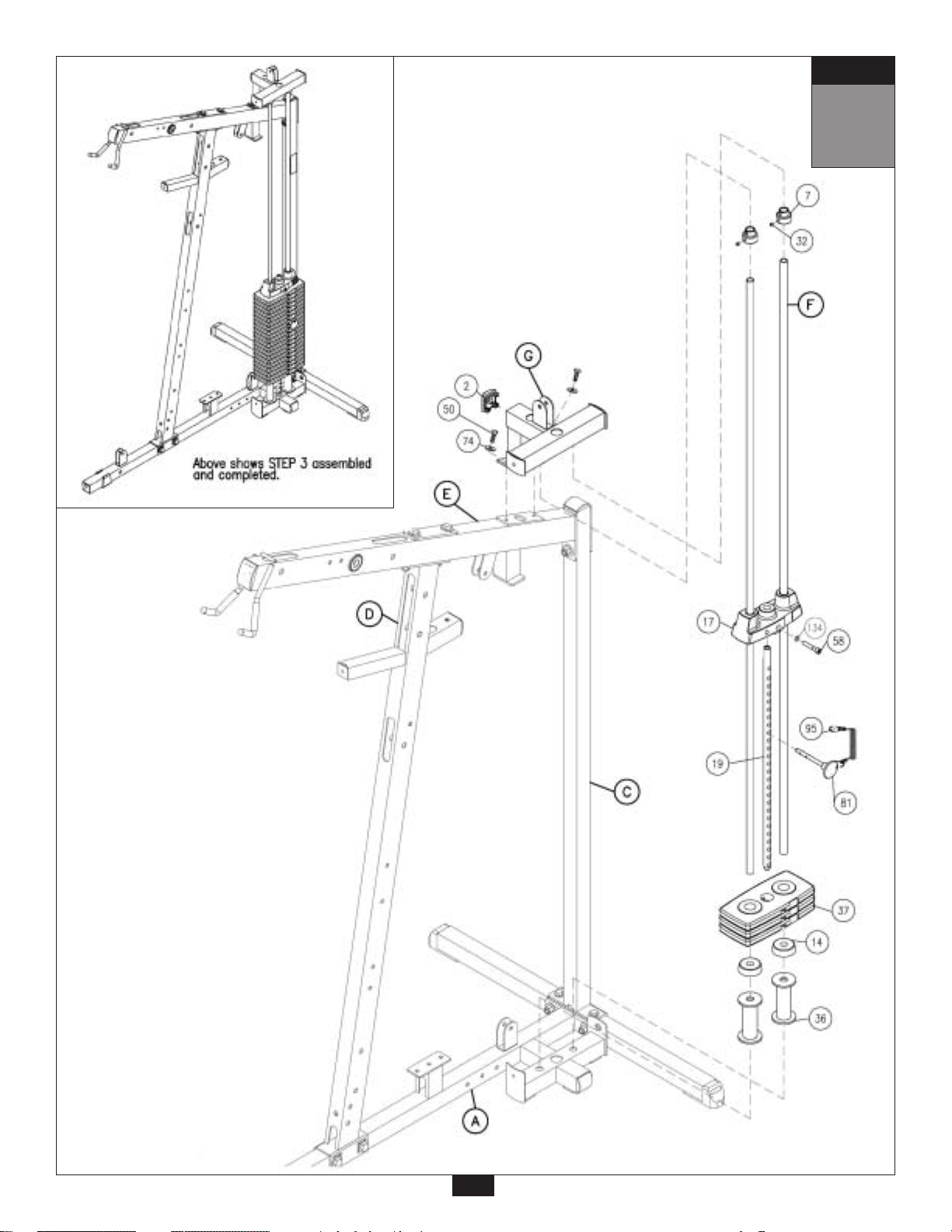
STEP
3
15
Page 16

STEP
4
Be careful to assemble all components
in the sequence they are presented.
A. Attach two Convex End Caps (2) to the top of Seated Press Arm Support (H).
Attach Seated Press Arm Support (H) to Top Frame (E) using Shaft (33), and tighten
Allen Screws (34).
B. Attach Bi Angular Bars (J) to Top Frame (E) using:
Two 53 (3/8” x 3” hex head bolt)
Four 74 (3/8” washer)
T
wo 71 (3/8” nylon lock nut)
Also using:
Two 80 (3/8” x 1/2” hex head bolt)
T
wo 79 (3/8” washer)
C. Attach Press Arm Holder (K) to Seated Press Arm Support (H) using Shaft (35), and tighten
Allen Scr
ews (34).
D. Attach Left Press Ar
One 37 (1/2” x 3/4” hex head bolt)
One 73 (1/2” washer)
And tighten Allen Screws (34).
E.
F
. Connect Bi Angular Bars (J) to Left Press Ar
G. Connect Bi Angular Bars (J) to Right Pr
Note:
You should now w
Attach Right Press Arm (M) to Pr
One 37 (1/2” x 3/4” hex head bolt)
One 73 (1/2” washer)
And tighten Allen Screws (34).
Two 74 (3/8” washer)
T
wo 36 (3/8” x 5/8” round allen bolt)
Two 74 (3/8” washer)
T
wo 36 (3/8” x 5/8” round allen bolt)
r
m (L) to Press Arm Holder (K) using Shaft (KA), and:
ench tighten all bolts and nuts in this step.
mm
ess Arm Holder (K) using Shaft (KB), and:
m (L) using Shaft (39) and:
ess Arm (M) using Shaft (39) and:
Inch
16
Page 17

STEP
4
17
Page 18

STEP
5
Be careful to assemble all components
in the sequence they are presented.
A. Attach Pec Dec Frame (N) to Angled Support Frame (D) in the bottom two holes as shown using:
One 42 (1/2” x 3 3/4” hex head bolt)*
Two 43 (1/2” x 3 1/4” hex head bolt)
Five 73 (1/2” washer)
Two 70 (1/2” nylon lock nut)
Attach two End Caps (15) to the top and bottom of the Pec Dec Frame (N) as shown.
*Note:
Hex Head Bolt (42) goes into an inter
Attach two Convex End Caps (2) to the sides of the Pec Dec Frame (N) as shown.
nally threaded nut inside Pec Dec Frame (N).
B. Slide Oilite W
side of the Pec Dec Frame (N) as shown, Attach using:
One 37 (1/2” x 3/4” hex head bolt)
One 73 (1/2” washer)
C. Attach Left Pec Dec Handle (R)* to the Left Pec Dec Arm (Q) using:
One 45 (5/16” x 3/4” flat allen head)
One 77 (5/16” spring lock washer)
Slide Chrome Collar (46) onto the bottom of the Left Pec Dec Handle (R) as shown, and tighten
Allen Scr
*Note:
Left Pec Dec Handle (R) should bend out, away from the the gym.
D. Slide Oilite Washer (26), Right Pec Dec Cam (S) and then the Right Pec Dec Ar
Right side of the Pec Dec Frame (N) as shown, attach using:
One 37 (1/2” x 3/4” hex head bolt)
One 73 (1/2” washer)
E. Attach Right Pec Dec Handle (U)* to the Right Pec Dec Arm (T) using:
One 45 (5/16” x 3/4” flat allen head)
One 77 (5/16” spring lock washer)
Slide Chrome Collar (46) onto the bottom of the Right Pec Dec Handle (U) as shown, and tighten
Allen Scr
*Note:
Right Pec Dec Handle (U) should bend out, away from the gym.
Note:
You should now wr
asher (26), Left Pec Dec Cam (P) and then the Left Pec Dec Arm (Q) onto the left
ew (34).
ew (34).
ench tighten all bolts and nuts in this step.
m (T) onto the
mm
Inch
18
Page 19
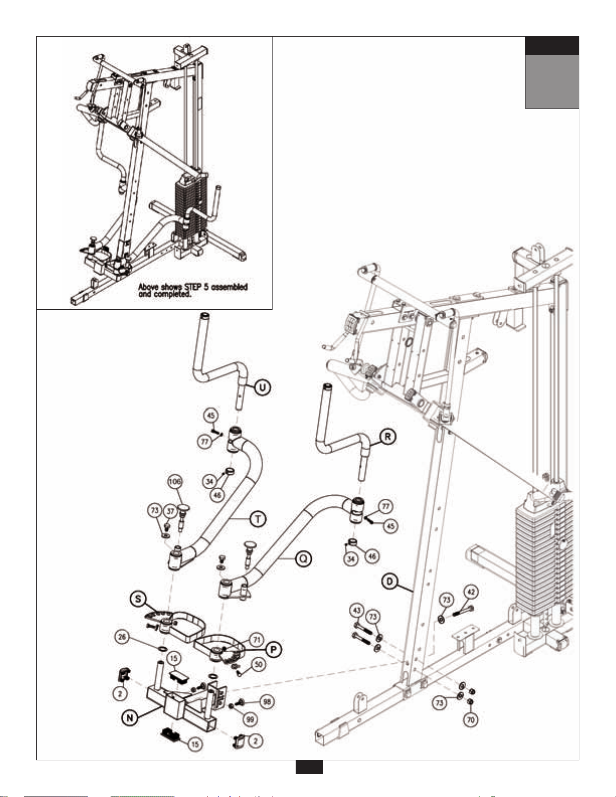
STEP
5
19
Page 20

STEP
6
Be careful to assemble all components
in the sequence they are presented.
NOTE:
LEG EXTENSION FRAME (V) AND THE SEAT PAD FRAME (W) ARE PRE-ASSEMBLED AS
ONE PIECE.
A. Attach Leg Extension Frame (V) to Angled Support Frame (D) using:
Two 40 (1/2” x 3 1/4” hex head bolt)
Four 73 (1/2” washer)
T
wo 70 (1/2” nylon lock nut)
B. Attach the bottom of Leg Extension Frame (V) to Main Base Frame (A) using:
One 44 (1/2” x 5 1/2” hex head bolt)
T
wo 73 (1/2” washer)
One 70 (1/2” nylon lock nut)
C. Attach Leg Extention Arm (X) to Leg Extension Frame (V) with pr
using:
Two 49 (5/16” x 1/2” round allen head bolt)
T
wo 76 (5/16” washer)
D. Tighten the two Allen Screws (34) to lock down Shaft (47) in Leg Extension Frame (V).
Attach two Convex End Caps (2) one to the top of Leg Extension Frame (V) and one to the top of
the Leg Extension Ar
E. Attach Lock Down Hook (152) to Leg Extension Frame (V) as shown in the REVERSE SIDE
DRAWING using:
One 57 (3/8” x 2 1/2” hex head bolt)
T
wo 73 (1/2” washer)
One 153 (5/16” wide spacer)
F. Attach Leg Extension Pad Holder (Y) and 1/4” Wide Spacer (154) to Leg Extension Ar
One 150 (1/2” x 4 1/2” hex head bolt)
Thr
ee 73 (1/2” washer)
One 70 (1/2” nylon lock nut)
G. Attach Leg Pads (AA) to Leg Extension Pad Holder (Y) using:
Four 61 (5/16” x 3/4” round allen head bolt)*
Four 77 (5/16” spring lock washer)
Four 76 (5/16” washer)
*
Do NOT over-tighten these bolts. Tighten these bolts until spring lock washer is flat.
Over - tightening these bolts will cause T - nuts in pads to strip out.
m (X) as shown.
e-installed Shaft (47) as shown
m (X) using:
Note:
You should now wr
Do NOT re-tighten any of the pad bolts.
ench tighten all bolts and nuts in this step.
mm
Inch
20
Page 21
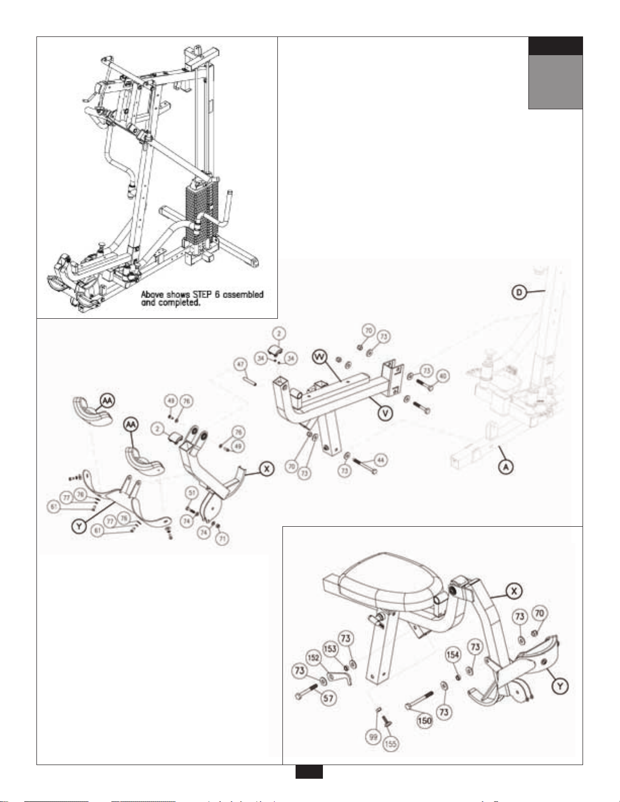
STEP
6
REVERSE SIDE DRAWING
21
Page 22

STEP
7
Be careful to assemble all components
in the sequence they are presented.
A. Attach Pulley Platform (AB) to Main Base Frame (A) as shown using:
Two 50 (3/8” x 1” hex head bolt)
Four 74 (3/8” washer)
Two 71 (3/8” nylon lock nut)
B. Attach two Pulley Swivels (AC) to Pulley Platform (AB) as shown using:
T
wo 59 (3/8”x 5/8” round allen head bolt)
T
wo 74 (3/8” washer)
Insert two Curved End Caps (3) into Pulley Platform (AB) as shown.
C.
*D
Over - tightening these bolts will cause T - nuts in pads to strip out.
D. Slide 4”x 8” Foam Rollers (18) onto Foam Roller Bar (38) and attach to Seat Pad Frame (V). Hold
E. Slide Foot Brace Adjuster (AE) into Main Base Frame (A) and hold in place with Pop Pin (63).
F.
Note:
You should now wr
Do NOT re-tighten any of the pad bolts.
Insert two Curved End Caps (3) into Seat Pad Frame (W) as shown.
Attach Seat Pad (AD) to Seat Pad Frame (W) using:
T
wo 62 (5/16” x 1 3/4” hex head bolt)*
T
wo 77 (5/16” spring lock washer)
Two 76 (5/16” washer)
o NOT over-tighten these bolts. Tighten these bolts untill spring lock washer is flat.
Foam Rollers (18) in place with 3” Plastic W
on the outside as shown.
Attach Foot Brace (AF) to Foot Brace Adjuster (AE) with Shaft (64).
Tighten Allen Screws (34).
Insert Round End Caps (27) to Foot Brace Adjuster (AE), and attach Grip Tape (16) to
Foot Brace (AF) as shown.
ench tighten all bolts and nuts in this step.
asher (8) on the inside and Plastic Roller End Cap (5)
mm
Inch
22
Page 23
STEP
7
23
Page 24

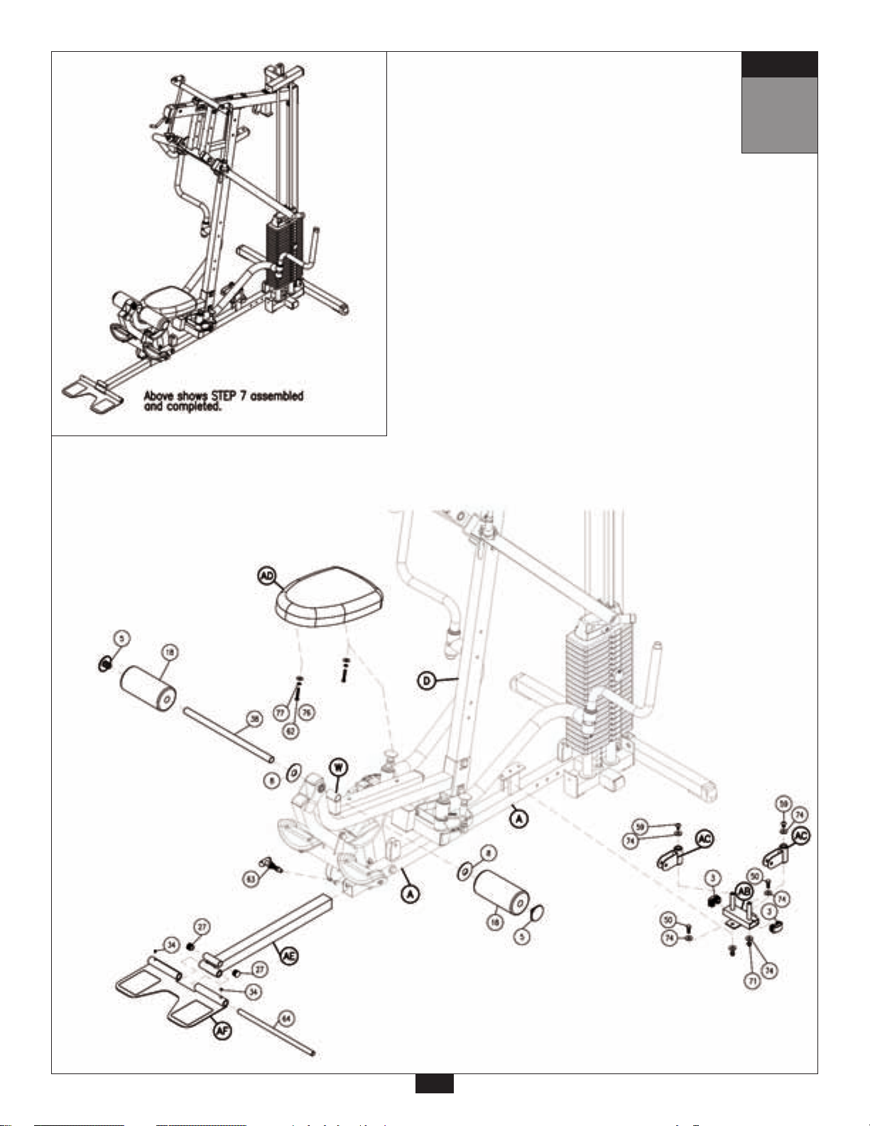
STEP
8
Be careful to assemble all components
in the sequence they are presented.
A. Attach Right Leg Hold Down (AG) and Left Leg Hold Down (AH) to the Angled Support Frame (D)
using:
Two 56 (3/8” x 3 1/4” hex head bolt)
Four 78 (3/8” washer)
Two 71 (3/8” nylon lock nut)
Slide two 4”x 8” Foam Rollers (18) onto the two Leg Hold Downs (AG) and (AH). Hold in place
with two
B. Insert two Nylon Bushings (31) into Back Pad Holder (BA).
Attach Back Pad Holder (BA) to Angled Suppor
Two 53 (3/8” x 3” hex head bolt)
Four 78 (3/8” washer)
T
wo 71 (3/8” nylon lock nut)
Plastic Roller End Caps (30).
t Frame (D) using:
C. Slide two Convex End Caps (3) into the top and bottom of Back Pad Frame (BC).
Attach Back Pad (BB) to Back Pad Frame (BC) using:
Two 60 (5/16” x 1 1/2” hex head bolt)*
T
wo 77 (5/16” spring lock washer)
Two 76 (5/16” washer)
*D
o NOT over-tighten these bolts. Tighten these bolts until spring lock washer is flat.
Over - tightening these bolts will cause T - nuts in pads to strip out.
D. Attach Back Pad Frame (BC) to Back Pad Adjuster (BD) with Pop Pin (65) and using:
One 59 (3/8” x 5/8” allen head bolt)
One 78 (3/8” washer)
E. Slide Convex End Cap (2) into the Back Pad Adjuster (BD).
Slide Back Pad Adjuster (BD) into Back Pad Holder (BA) and hold in place with Pop Pin (63) and
using:
One 66 (5/16” x 1/2” flat allen head bolt)
One 76 (5/16” washer)
NOTE:
Y
ou should now make sure all bolts and nuts are
Do NOT re-tighten any of the pad bolts.
Also, leave all pulley bolts finger-tight untill after STEP 15.
ench tight.
wr
mm
Inch
24
Page 25
STEP
8
25
Page 26

STEP
9
Be careful to assemble all components
in the sequence they are presented.
NOTE:
Leave all pulley bolts hand tight until step 15 is completed.
A. Install Pulley (A3) and Pulley (A5) into Seated Press Arm Support (H) using for each pulley:
One 54 (3/8” x 7 1/4” hex head bolt)
Two 74 (3/8” washer)
Two 83 (steel bushing)
One 71 (3/8” nylon lock nut)
B. Install Pulley (A8) into the pulley flange on T
One 51 (3/8” x 1 3/4” hex head bolt)
Two 74 (3/8” washer)
One 71 (3/8” nylon lock nut)
C. Install Pulley (B6) onto Main Base Frame (A) as shown using:
One 51 (3/8” x 1 3/4” hex head bolt)
T
wo 74 (3/8” washer)
One 71 (3/8” nylon lock nut)
D. Install Pulley (B7) onto Main Base Frame (A) as shown using:
One 51 (3/8” x 1 3/4” hex head bolt)
T
wo 74 (3/8” washer)
One 71 (3/8” nylon lock nut)
op Frame (E) as shown using:
mm
Inch
26
Page 27

STEP
9
27
Page 28

STEP
10
Be careful to assemble all components
in the sequence they are presented.
High Pulley Cable (85)
Ball Stop End
5110 mm
Note:
Leave all pulley bolts hand tight until step 15 is completed.
A. Begin at the high pulley station. Route the metal ball end of the High Pulley Cable (85) up
through the opening where Pulley (A1) will be installed. Route the metal ball end under the
Bi-Angular Bars (J) and then down
B. Install Pulley (A1) under Cable (85) and into Top Frame (E) as shown using:
One 52 (3/8” x 2 3/4” hex head bolt)
T
wo 84 (nylon bushing)
One 71 (3/8” nylon lock nut)
C. Install Pulley (A2) under Cable (85) and into Top Frame (E) as shown using:
One 52 (3/8” x 2 3/4” hex head bolt)
T
wo 84 (nylon bushing)
One 71 (3/8” nylon lock nut)
D. Route Cable (85) over
Route Cable (85) around Pulley (A4) and install Pulley (A4) into Angled Support Frame (D) using:
One 52 (3/8” x 2 3/4” hex head bolt)
Two 84 (nylon bushing)
One 71 (3/8” nylon lock nut)
the top and around pre-installed Pulley (A3) as shown.
through the next opening where Pulley (A2) will be installed.
16’ 9”
Metal Ball End
and
E. Route Cable (85) between Pulley (A3) and pre-installed Pulley (A5).
Route Cable (85) ar
ound Pulley (A5) and back through Angled Support Frame (D).
mm
Inch
28
Page 29

Diagram 1
Cable Installation
Start here at high pulley
station by inserting the
metal ball end here.
STEP
Lat Pulldown
Cable
10
Diagram 2
Pulley Installation
29
Page 30

STEP
11
Be careful to assemble all components
in the sequence they are presented.
High Pulley Cable (85)
Ball Stop End
5110 mm 16’ 9”
Note:
Leave all pulley bolts hand tight until step 15 is completed.
A. Install Pulley (A6) under Cable (85) and into Angled Support Frame (D) using:
One 52 (3/8” x 2 3/4” hex head bolt)
Two 84 (nylon bushing)
One 71 (3/8” nylon lock nut)
Route Cable (85) down
B. Route Cable (85) through the top of the Double Pulley Holder (CA). Install Pulley (A7) using:
One 51 (3/8” x 1 3/4” hex head bolt)
T
wo 74 (3/8” washer)
One 71 (3/8” nylon lock nut)
through the small arm sticking out of the Angled Support Frame (D).
Metal Ball End
C. Route Cable (85) up
Pulley Holder (CB).
Route Cable (85) through the top of the 45 Degree Double Pulley Holder (CB). Install Pulley (A9) using:
One 51 (3/8” x 1 3/4” hex head bolt)
T
wo 74 (3/8” washer)
One 71 (3/8” nylon lock nut)
C. Route Cable (85) up
One 51 (3/8” x 1 3/4” hex head bolt)
Two 74 (3/8” washer)
One 71 (3/8” nylon lock nut)
Route Cable (85) up
stack.
D. The Metal Ball End of Cable (85) should be hanging just above the weight stack. Remove Allen Bolt (102)
from Selector Rod Top Bolt (103), slide Metal Ball End of Cable (85) through Selector Rod Top Bolt (103).
Attach Cable End Shaft (100) and securely tighten Allen Bolt (101). Pull Cable (85) tight, so Cable End
Shaft (100) fits securely inside Selector Rod Top Bolt (103). Reinstall Allen Bolt (102) in Selector Rod Top
Bolt (103) and tighten Nylon Lock Nut (71) to hold in place.
NOTE:
Make sur
inch. Make sure Spring Lock Washer (105) is in place and wrench tighten Jam Nut (104).
e the Selector Rod Top Bolt (103) is threaded inside Selector Rod (19) at least one half
to Top Frame (E), over pre-installed Pulley (A8), and down to 45 Degree Double
through the Top Weight Stack Frame (G). Install Pulley (A10) using:
over Pulley (A10) and down through Top Weight Stack Frame (G) and toward weight
mm
Inch
30
Page 31

Diagram 1
Cable Installation
STEP
Lat Pulldown
Cable
11
Diagram 2
Pulley Installation
!
WARNING
Selector Rod Top Bolt (103) must be threaded a
minumum of 1/2” into the Selector Rod (19), and
Jam Nut (104) tightened securely against spring
lock washer (105) to ensure proper connection.
Check the Jam Nut (104) once a week to make
sure it is tight.
!
31
Page 32

STEP
12
Be careful to assemble all components
in the sequence they are presented.
Low Pulley Cable (86)
Small Ball Stop End
5080 mm 16’ 8”
Note:
Leave all pulley bolts hand tight until step 15 is completed.
A. Insert either end of Low Pulley Cable (86) into the opening in Angled Support Frame (D),
above Back Pad (BB), and pull entir
B. Install Pulley (B1), under
One 57 (3/8” x 2 1/2” hex head bolt)
Two 84 (nylon bushing)
One 71 (3/8” nylon lock nut)
C. Route Cable (86) through the top of the 90 Degr
installing Pulley (B2) using:
One 51 (3/8” x 1 3/4” hex head bolt)
T
wo 74 (3/8” washer)
One 71 (3/8” nylon lock nut)
Cable (86) and into Angled Support Frame (D) as shown using:
e length of Cable (86) through.
ee Pulley Holder (CC) and hold in place by
Small Ball Stop End
D. Route Cable (86) up
One 51 (3/8” x 1 3/4” hex head bolt)
Two 74 (3/8” washer)
One 71 (3/8” nylon lock nut)
E. Route Cable (86) down
One 51 (3/8” x 1 3/4” hex head bolt)
Two 74 (3/8” washer)
One 71 (3/8” nylon lock nut)
mm
Inch
and through the bottom of Double Pulley Holder (CA). Install Pulley (B3) using:
and through the Single Pulley Holder (CD). Install Pulley (B4) using:
32
Page 33

Diagram 1
Cable Installation
Start here at the Ab-Crunch
station by inserting either
end here.
STEP
12
Low Pulley Cable
Diagram 2
Pulley Installation
33
Page 34

STEP
13
Be careful to assemble all components
in the sequence they are presented.
Low Pulley Cable (86)
Small Ball Stop End
Small Ball Stop End
5080 mm
16’ 8”
Short Cable (87)
Stamped Eye End
757 mm
NOTE:
Leave all pulley bolts hand tight until step 15
A. Route Cable (86) up
Pulley (B5) using:
One 51 (3/8” x 1 3/4” hex head bolt)
Two 74 (3/8” washer)
One 71 (3/8” nylon lock nut)
B. Route Cable (86) down
Route Cable (86) forward and through the opening in Angled Support Frame (D).
Route Cable (86) under
Insert Cable (86) through Leg Extension Arm (X) and install Pulley (B8) using:
One 51 (3/8” x 1 3/4” hex head bolt)
Two 74 (3/8” washer)
One 71 (3/8” nylon lock nut)
E. Attach Short Cable (87) to Main Base Frame (A) as shown using:
One 53 (3/8” x 3” hex head bolt)
T
wo 74 (3/8” washer)
One 71 (3/8” nylon lock nut)
and through the bottom of 45 Degree Double Pulley Holder (CB). Install
, around pre-installed Pulley (B6). Remove and re-install pulley as needed.
pre-installed Pulley (B7). Remove and re-install pulley as needed.
Stamped Eye End
2’ 6”
F. Attach the other end of Cable (87) to the hook on the bottom of Pulley Holder (CD) as shown.
mm
Inch
34
Page 35

Diagram 1
Cable Installation
STEP
13
Low Pulley
Cable
Short Cable
Diagram 2
Pulley Installation
Short Cable 87
Diagram
35
Page 36

STEP
14
Be careful to assemble all components
in the sequence they are presented.
Pec Dec Cable (88)
Stamped Eye End
2055 mm 6’ 9”
NOTE:
Leave all pulley bolts hand tight until step 15
A. Bolt Pec Dec Cable (88) to Left Pec Dec Cam (P) as shown in diagram 1 using:
One 50 (3/8” x 1” hex head bolt)
One 71 (3/8” nylon lock nut)
B. See diagram 1. Route Cable (88) through Pulley Swivel (AC) on the left side, hold cable in place
with Pulley (C1) using:
One 51 (3/8” x 1 3/4” hex head bolt)
T
wo 74 (3/8” washer)
One 71 (3/8” nylon lock nut)
C. See diagram 1. Route Cable (88) up and into 90 Degree Double Pulley Holder (CC) and install
Pulley (C2) using:
One 51 (3/8” x 1 3/4” hex head bolt)
T
wo 74 (3/8” washer)
One 71 (3/8” nylon lock nut)
B. Insert Cable (88) thr
Pulley (C3) as shown in diagram 2 using:
One 51 (3/8” x 1 3/4” hex head bolt)
T
wo 74 (3/8” washer)
One 71 (3/8” nylon lock nut)
ough Pulley Swivel (AC) on the right side, hold cable in place by installing
Stamped Eye End
C. Attach Cable (88) to Right Pec Dec Cam (S) as shown in diagram 1 using:
One 50 (3/8” x 1” hex head bolt)
One 71 (3/8” nylon lock nut)
mm
Inch
36
Page 37

Diagram 1
Cable Installation
Pec Dec
Cable
Diagram 2
Cable Installation
STEP
14
Pec Dec Cable
Start routing cable here
by bolting cable to Left
Pec Dec Cam (P).
Diagram 3
Pulley Installation
37
Page 38

STEP
15
Be careful to assemble all components
in the sequence they are presented.
NOW IS THE TIME TO MAKE ALL NECESSARY
CABLE ADJUSTMENTS
After cable installation is complete you must check all cables for proper tension. Obvious signs that
cable tension problems exist include:
c Top Plate (17) does not rest directly on the top Weight Stack Plate (38).
c The holes in the Selector Bar (19) do not line up with holes in the Weight Stack Plates (38).
c Cable(s) are sloppy and there is no resistance from the weight stack for the first few
inches of the exer
cise.
There are FIVE ar
A. Selector Rod Top Bolt (103).*
B. TWO adjustments in Double Pulley Holder (CA).
C. TWO Rubber Stops (98) and (155).
*SEE NOTE 1 ON PAGE 39
If there is to much tension, and the Top Plate (17) is not resting directly on the top weight stack plate:
1st. -Move pulley (A7) up, or Pulley (B3) down in the Double Pulley Holder (CA).
2nd. Turn and tighten one of the Rubber Stops (98) and (155).
If there is to much play or excessive slack:
1st. -T
2nd. Move Pulley (A7) down, or Pulley (B3) up in the Double Pulley Holder (CA).
3rd. -Screw the Selector Rod Top Bolt (103) farther into the Selector Rod (19).
NOTE:
Cables should be inspected daily and adjusted periodically to ensure safe and
smooth operation.
NOTE:
After cable adjustment is complete, go back and tighten all pulley bolts.
eas for cable adjustment on the G6B:
urn and loosen the Rubber Stops (98) and (155).
38
Page 39

STEP
15
Turn and loosen Rubber Stop (98)
to take up space and tighten cable.
Loosen
Turn and loosen Rubber Stop (105)
to take up space and tighten cable.
!
WARNING
Selector Rod Top Bolt (103) must be
threaded a minimum of 1/2” into the
Loosen
Selector Rod (19), and Jam Nut (104)
tightened securely against spring lock
washer (105) to ensure proper connection.
39
NOTE 1
Check Jam Nut (104)
weekly to be sure it is
tight and locked onto
the Selector Rod (19).
!
Page 40

STEP
16
Be careful to assemble all components
in the sequence they are presented.
SEE NOTE 1 ON PAGE 41:
A. Apply weight stack numbers to weight stack Top Plate (17) and each Weight Stack Plate (38)
as shown.
SEE NOTE 2 ON PAGE 41:
B. Weight Stack Shroud (DA) is pre-assembled with Shroud Insert (DB).
Attach W
Bolt onto Main Base Frame (A) at the bottom and Top W
Two 89 (3/8” x 5/8” round allen head)
T
wo 74 (3/8” washer)
eight Stack Shroud (DA) to the side of the weight stack as shown.
eight Stack Frame (G) using:
C. Attach Back Weight Stack Shr
Frame (A) at the bottom and to the T
Two 89 (3/8” x 5/8” r
Two 74 (3/8” washer)
D. Attach Press Ar
Four 90 (1/8” x 3/8” round allen head)
E. Connect the Water Bottle Bracket (91) to the Weight Stack Shroud (DA) using:
Two 92 (1/8” x 3/8” screw)
F. Slide the Water Bottle Holder (93) onto the Water Bottle Bracket (91) as shown.
m Shroud (DD) to the Seated Press Arm Support (H) using:
oud (DC), to the back side of the weight stack, onto the Main Base
op Weight Stack Frame (G) as shown using:
ound allen head)
mm
Inch
40
Page 41

NOTE 2
This is the top view of the two Weight Stack Shrouds.
Note the shape of each shroud for proper placement.
2” flat side
3/4” flat side
STEP
16
#1
41
NOTE 1
#2
Apply weight stack numbers to the Weight
Stack Plates (38). Start at the Top Plate (17)
with the number 1, and the first plate
should be number 2. The following Weight
Stack Plates (38) should be numbered in
sequential order down through the stack.
Page 42

Adjustments
Congratulations! You are done. After assembly, you should check all functions to ensure correct
operation. If you experience problems, first recheck the assembly instructions to locate any possible
errors made during assembly. If you are unable to correct the problem, call the dealer from whom you
purchased the machine or call 1-800-833-1227 for the dealer nearest you.
Note: If any bolts seem to loosen periodically, use Loctite 242 for a long-term cure.
This gym is capable of a variety of different exercises, as well as, smooth and user-friendly adjustment
features. The following pages of adjustments will help you to familiarize yourself with your new gym. We
hope you are completely satisfied with this product and wish you many years of enjoyment.
1. SEATED PRESS ARMS ADJUSTMENT
A. Grasp the Right Press Arm (M) with one hand.
B. Pull the Flat Head Pop Pin (94) with your other hand to release the Press Arm Holder (K).
C. Adjust the Press Arm Holder (K) to the desired position (depending on the exercise
you are performing).
D. Release the Flat Head Pop Pin, and make sure it is fully
selector hole.
engaged into the
2. BACK PAD (BB) ADJUSTMENT
A. Grasp Back Pad (BB).
B. Turn the T-Shaped Pop Pin (63) in Back Pad Holder (BA) counter clockwise to unlock it,
and then pull the Pop Pin to release the Back Pad Adjuster (BD). Adjust the Back
Pad to the desired position.
C. Release the T-Shaped Pop Pin (63) and make sure it is fully
hole in the Back Pad Adjuster (BD). Turn T-Shaped Pop Pin clockwise to lock it in place.
D. For certain exercises you may wish to change the angle of the Back Pad.
Pull the T-Shaped Pop Pin (65) on the Back Pad Adjuster (BD), this will allow you
to change to the desired angle.
E. Release the T-Shaped Pop Pin (65) and make sure it is fully
engaged into the selector
engaged into the selector hole.
42
Page 43

WARNING
!
Pay special attention to the plunger on this Pop Pin (65).
Always be sure that the plunger is fully engaged into the hole
you select. Also, be sure that the spring in the Pop Pin (65)
operates freely. Failure to do so may result in serious injury.
!
1.
!
Pay special attention to the plunger on both Pop Pins (63) and (65).
Always be sure that the plunger is fully engaged into the hole you
select. Also, be sure that the spring in both Pop Pins (63) and (65)
operates freely. Failure to do so may result in serious injury.
WARNING
!
2.
43
Page 44

Adjustments
3. SEAT PAD (AD) ADJUSTMENT
A. Grasp the Seat Pad (AD).
B. Turn the T-Shaped Pop Pin (63) in Leg Extension Frame (W) counter clockwise to unlock
it, and then pull the Pop Pin to release the Seat Pad Frame (W).
C. Adjust the Seat Pad (AD) to the desired position.
D. Release the T-Shaped Pop Pin and make sure it is fully engaged into the selector
hole. Turn T-Shaped Pop Pin (63) clockwise to lock it in place.
4. FOOT BRACE (AE) ADJUSTMENT
A. Grasp the Foot Brace Adjuster (AE).
B. Turn the T-Shaped Pop Pin (63) in Main Base Frame (A) counter clockwise to unlock it,
then pull to release the Foot Brace Adjuster (AE).
C. Adjust to the desired position.
D. Release the T-Shaped Pop Pin and make sure that it is fully
hole in the Foot Brace Adjuster (AE). Turn clockwise to lock in place.
engaged into the selector
5. PEC DEC ARMS (Q),(T) ADJUSTMENT
A. Grasp Pec Dec Arm (Q) or (T).
B. Pull the Flat Pop Pin (106) to release the Pec Dec Arm (Q) or (T).
C. Adjust the Pec Dec Arm to the desired position.
D. Release the Ball Head Pop Pin (106) and make sure that it is fully
selector hole.
engaged into the
44
Page 45

!
Pay special attention to the plunger on this Pop Pin (63).
Always be sure that the plunger is fully engaged into the hole
you select. Also, be sure that the spring in the Pop Pin (63)
operates freely. Failure to do so may result in serious injury.
WARNING
!
3.
5.
4.
!
Pay special attention to the plunger on this Pop Pin (104). Always be
sure that the plunger is fully engaged into the hole you select. Also,
be sure that the spring in the Pop Pin (104) operates freely. Failure
to do so may result in serious injury.
WARNING
!
Pay special attention to the plunger on this Pop Pin (63).
Always be sure that the plunger is fully engaged into the hole
you select. Also, be sure that the spring in the Pop Pin (63)
operates freely. Failure to do so may result in serious injury.
45
!
WARNING
!
Page 46

Warning, Safety & Maintenance
Be sure that all users carefully read and understand all
warning, safety and maintenance labels on the machine
before each use. Failure to do so may result in serious injury.
It is imperative that you retain this Owner’s Manual and be
sure all warning labels are legible and intact. Replacement
Owner’s Manuals and labels are available from your local
Body-Solid dealer. If you have any questions about the
operation, set up or maintenance of this machine please call
our customer service department at 1 (800) 556-3113.
#DWRULE-4
Warning Label for Rules
#DWSM-5
Warning Label for Maintenance
46
Page 47

Warning
Safety and Maintenance of Cables
Although Body-Solid provides the highest quality of materials and
workmanship in its products, the fact remains that component parts eventually wear
out over time and with use. This is particularly true with reference to pliable
moving parts such as cables. In spite of any expressed and/or implied warranties,
intervening factors such as improper use, unusually heavy use, improper installation,
improper alignment, poor maintenance, etc. serve to drastically reduce the usable
life and safety of cables.
Be advised that dangerous conditions can arise even during warranty
periods and that any expressed and/or implied warranties Do Not Negate the
owner’s responsibility to thoroughly, carefully and daily inspect all cables on this
machine.
Serious injury can occur if you are struck by falling weights or moving parts.
The risk that you assume by using this type of equipment can be reduced by
following a few simple steps:
Cable inspection should be performed daily
nylon coating on all cables and the area near the fittings at each end of each cable.
Replace any damaged or worn cables immediately. Do not allow the machine to
be used until damaged or worn cables are replaced.
Important: Cables are wear items. It is your responsibility to prevent
unexpected breakage. The actual wire strands, the fittings and the nylon coating
itself must all be scrutinized. Using or allowing a machine to be used with a suspect
cable can result in serious injury.
The nylon coating on a cable is essential for cable life and safety. V
inspect all cables and pulleys. Look at the cables as they travel around the cams
and pulleys. Acable that is wearing may exhibit a “ballooned” or broken coating in
the area that passes over the pulley. Damage to the coating is an early warning
signal. Acable should be replaced if the nylon coating is missing, is damaged in
anyway, has pulled or shrunk from the fittings at the end of the cables, or if it is
discolored. Discoloration of the cable coating is an early indication of internal
problems such as wear or fraying.
Annual cable replacement (semiannual in multi-user settings) is strongly
recommended as an additional precaution. The rate at which cables wear depends
on many factors including: number of users, number of repetitions, weight setting,
misuse, abuse, etc. Because of this, periodic cable replacement is not a sufficient
safeguard against unexpected breakage.
Nothing short of a thorough, careful, daily inspection constitutes an
adequate safety program.
. Inspect all cables, the
isually
47
Page 48

Warning, Safety & Maintenance
Precision craftsmanship assures Body-Solid’s ability to
consistently deliver products of the highest standards. Our
products have been carefully designed to ensure safe, efficient
long term operation.
However, it must be realized that safe use of this equipment
requires that owners carefully read and follow the Body-Solid
use recommendations, warnings, and maintenance guidelines
in this Owners Manual.
Routine inspection and maintenance is of critical importance to
ensure the maximum safety and performance of the G6B.
Body-Solid uses the highest quality materials available, but wear
is inevitable. Therefore, you must carefully inspect your
equipment as outlined in the Maintenance Schedule on the next
page.
Be advised that dangerous conditions can arise even during a
warranty period. A warranty does not negate the owner’s
responsibility to thoroughly, carefully and daily inspect the
machine.
Including maintaning the equipment the owner’s responsibility is
also to:
l Be sure to always provide adequate
supervision to all end-users.
l Be sure to instruct all end-users of proper
usage.
l Be sure all supervisors and personal trainers
who instruct end-users on equipment use ar
properly trained and know the function and
importance of ever
Also, be sure these trainers provide proper
instruction to end-users on the fundamentals
of strength training.
y adjustment and setting.
e
CABLES:
UPHOLSTERY:
NUTS/BOLTS/F
GUIDE RODS:
l While the machine is not in use. Carefully run your
fingers along the cable to feel for thinning or
bulging ar
the first sign of damage or wear. Do not use
equipment until damaged cable has been
replaced.
isually inspect the cables for fraying, cracking,
l V
peeling or discoloration.
l Check slack in cables and re-adjust cable tension
if needed. See pages 38-39.
l Check that the jam nut on the selector rod top
bolt is tight.
l Wipe down after every workout.
l Periodically take the time to use a mild soap or a
mild vinyl upholster
abrasive cleaner not intended for use on vinyl.
l Keep sharp or pointed objects out of your
pockets and clear of all upholster
l Periodically inspect all nuts and bolts. Tighten if
needed. If bolts seem to loosen periodically, use
Loctite 242 for a long-term cure.
l Go thr
to ensure that all hardware is pr
l Wipe clean with a dust free rag. Lubricate with a
Silicon or Teflon based lubricant.
eas. Replace cables immediately at
y cleaner. Avoid using any
y.
ASTENERS:
ough a re-tightening sequence periodically
operly tensioned.
ADJUSTMENTS / LOCKING PINS / TIGHTENING
KNOBS:
ANTI-SKID SURFACES:
WARNING INSTRUCTION LABELS:
l Check all pieces for signs of visible wear or
damage.
l Check springs in Snap Links and Pop Pins for
proper tension and alignment.
l If the spring sticks or has lost its rigidity, replace
it immediatly
l Replace if they appear worn or become slipper
l Inspect and familiarize yourself with all safety
warnings and other user information on decals.
.
y.
48
Page 49

MAINTENANCE
SCHEDULE
CABLES: CHECK TENSION, END FITTINGS, AND
COATING.
CHECK THAT JAM NUTON THE SELECTOR ROD TOP
BOLT IS TIGHT.
UPHOLSTERY: WIPE DOWN AND DRY
CLEAN AND CONDITION.
FRAME: WIPE DOWN AND DRY
POLISH/WAX
CHROME: WIPE DOWN AND DRY
POLISH/LUBRICATE
NUTS/BOLTS/FASTENERS:
TIGHTEN AND/OR ADJUST AS NEEDED
GUIDE RODS:
LUBRICATE AND CLEAN
LINEAR RODS:
LUBRICATE AND CLEAN
DAILY
a
a
a
a
WEEKLY
a
a
a
a
a
a
LATEST DATE ENTRY
SEAT SLEEVES:
LUBRICATE AND CLEAN
ADJUSTMENTS / LOCKING PINS /
TIGHTENING KNOBS
WEIGHT STACK PINS
WARNING INSTRUCTION LABELS
SPRINGS / POP PINS
ANTI-SKID SURFACES
HAND GRIPS / ROLLERS
a
a
a
a
a
a
a
a
FOR BODY-SOLID CUSTOMER SERVICE:
1-800-556-3113
*Make several copies of this page to keep track of your maintenance.
You can print more copies of this page by going to:
http://www.bodysolid.com/support/docs.html
49
Page 50

PHRASES, TERMS, TIPS
& GUIDELINES
BEGINNER’S GUIDELINES
• Work out at least two times a week.
• Include six to eight exercises that train major muscle groups.
• Perform two or three sets of at least eight to 12 repetitions.
AEROBIC
Exercise that primarily uses oxygen to burn fuel at low to moderate levels of intensity. Running
and jogging are examples of aerobic exercise.
ANAEROBIC
Exercise that primarily uses the body’s stored fuel for energy. Intense weightlifting is an
example of an anaerobic exercise.
ATROPHY
Decrease of a muscle caused by the decrease in the size of its cells because of inactivity.
EXERCISE LARGE MUSCLES FIRST
You should work your large muscle groups first (ie. squat, bench press, lat pulldown) before
you exercise your small muscle groups (ie. bicep curls, tricep pressdowns, lateral raises).
EXERCISE PROGRAM DURATION
A weight training routine should take anywhere from 45 minutes to one hour to complete. Add
another 20 to 60 minutes when you include stretching, warm-up, aerobics and cool-down.
GIVE YOUR MUSCLES A REST
You’ll get the most out of strength training if you give your muscles at least 48 hours rest to
recover and rebuild between strength training workouts.
BALLISTIC STRETCHING
A stretching technique that involves a bouncing or bobbing movement during the stretch. The
final position is not held. This is not
a recommended stretching technique.
HYPERTROPHY
Enlargement of a muscle caused by an increase in the size of its cells in response to weight
training.
BREATHING
Never hold your breath during any part of an exercise. Holding your breath may cause severe
intra-thoracic pressure and raise blood pressure leading to dizziness, blackout or other
complications. The rule of thumb is to exhale on exertion and inhale on the return part of the
exercise.
CARDIOVASCULAR
Referring to the heart, lungs, and other periphery systems involved in the transport of oxygen
throughout the body.
INTENSITY
The degree to which the body is worked during exercise.
ISOKINETIC EXERCISE
Resistance is given at a fixed velocity of movement with accommodating intensity. A machine
that moves you through an entire range of motion at a preset speed and will not change no
matter how much pressure is put forth by the individual.
ISOMETRIC EXERCISE
CHALLENGE YOUR MUSCLES
All strength training should progress gradually, using increases in weight until your goals are
reached. Then, change your workout to include increased reps or a higher weight resistance.
Alter the order of your exercises, perform multiple sets or different exercises to maintain
results or reach new goals.
Contracts the muscle statically without changing its length. Example: Attempting to lift a
weight heavier than you can handle, but cannot move.
ISOTONIC EXERCISE
Shortens and lengthens the muscle through a complete range of motion. This defines weight
training with full range of motion.
CHANGE ROUTINE
Beginner’s please note: If you want to make changes in the exercise routine that you do,
wait until about the six to eight week point. Advanced lifters may want to change routines to
avoid plateus in gaining size or strength.
MUSCLE FATIGUE
Fatigue is when you can’t possibly do another rep without sacrificing form.
MUSCULAR ENDURANCE
CIRCUIT TRAINING
Exercise stations that consist of various combinations of weight training, flexibility,
calisthenics, and aerobic exercise.
The ability to perform repetitive muscular contractions against some resistance.
MUSCULAR STRENGTH
The maximum force that can be applied by a muscle during a single maximum contraction.
CONCENTRIC MUSCLE ACTION
The muscle shortens while contracting against resistance.
OSTEOPOROSIS
A decrease in bone density.
ECCENTRIC MUSCLE ACTION
The muscle lengthens while contracting against resistance.
EXERCISE FREQUENCY
Exercise each muscle group 2-3 times per week. Allow a minimum of 48 hours rest for each
muscle group worked. If you are doing a total-body workout, three training sessions per
week, performed on every second day, is adequate.
PLYOMETRIC EXERCISE
A technique that includes specific exercises which encompass a rapid stretch of a muscle
eccentrically, followed immediately by a rapid concentric contraction of that muscle for the
purpose of facilitating and developing a forceful explosive movement over a short period of
time. Examples of these are using medicine balls for upper extremity and depth jumping for
lower extremeity.
50
Page 51

PHRASES, TERMS, TIPS
& GUIDELINES
STARTING RESISTANCE LEVEL
If you begin weight training at too high a level, you risk serious injury. You will also develop poor form,
which will hinder your efforts and discourage you. Use this as a guideline: if you cannot lift the weight
eight times with proper form, the weight is too heavy. Similarly, don’t choose too light a weight; the
last two or three repetitions of your set should be difficult.
POWER
Power is the rate of performing work. Power during a repetition is defined as the weight
lifted times the vertical distance the weight is lifted divided by the time to complete the
repetition. Power during a repetition can be increased by lifting the same weight the same
vertical distance in a shorter period of time. Power can also be increased by lifting a heavier
resistance the same vertical distance in the same period of time as a lighter resistance.
REST INTERVAL
Allow a brief pause between sets to give your muscles a chance to partially recover before
working them again. For power and muscle size development allow a 3 to 4 minute rest
interval between sets. For muscular endurance and definition allow a 30 second rest interval.
For strength training allow a 60 to 90 second rest interval.
RISK SHOULD NOT EXCEED BENEFIT
PROGRESS GRADUALLY
Increase reps before increasing resistance. Reduce rest intervals between sets to increase
intensity.
PROGRESSIVE RESISTANCE
The principle of continually adding more weight to a specific exercise as your muscles
become stronger to adapt to the heavier weights.
If the risk of a specific exercise exceeds its potential benefit, it is best to stay on the
conservative side. There are several ways to work specific muscle groups. Choose those that
provide minimal risk. Ask a fitness professional for guidance.
ROUTINE
The specific exercises, sets, reps and weight for a specific body part.
SET
PROPER FORM
Focus on the proper motion of the exercise and concentrate on the specific muscles being
used. Do not sacrifice proper form to lift heavier weight or to perform more repetitions. Proper
form also means lifting in a smooth, fluid motion. If you feel strain elsewhere, you should
re-evaluate the amount of weight you are lifting or have a qualified professional critique your
exercise motion.
PROPER POSTURE
Maintaining proper posture will greatly reduce chances of injury and maximize exercise
benefit. When standing always keep your feet shoulder-width apart. Do not lock your knees.
Locking your knees can put unnecessary strain on them. Keep your back flat and straight,
making sure not to twist or arch it in order to complete a repetition.
This is a group of repetitions performed continuously without stopping. While a set can be
made up of any number of repetitions, sets typically range from 1 to 15 repetitions.
SMALL MUSCLE GROUP EXERCISE
Single joint movement and isolation exercises (i.e. bicep curls, tricep pressdowns and leg
extensions).
SPEED OF MOVEMENT
Strength training movements should be slow and controlled. Do not use momentum to complete
an exercise movement. Momentum puts unnecessary stress on tendons, ligaments and joints.
Using momentum in your exercise movements does not develop increased strength.
STATIC STRETCHING
PROPER TECHNIQUE
To get the most out of strength training and to reduce the chance of injury, use proper weight
training techniques. These include working your muscles through their full range of motion
(but not locking any joints), lifting at a speed at which you can control the weight and stop
easily if necessary.
RANGE OF MOTION
Moving through a complete range of motion (ROM) allows the muscles to stretch before
contraction and increases the number of muscle fibers being recruited. This produces
maximum contraction and force. By working the full ROM, flexibility will be maintained and
possibly increased.
A stretching technique that involves holding a specific muscle or muscle group at a desired
length for a certain period of time. This type of stretching is highly recommended.
STOP TRAINING IF YOU FEEL PAIN
If you feel pain during a specific exercise stop immediately. Any continuation may aggravate
an existing injury. Re-evaluate your routine to make sure that you are doing a proper warm up.
Decrease the amount of weight you are lifting. Talk to a qualified personal trainer, health
professional or your doctor.
STRENGTH
Strength is the maximal amount of force a muscle or muscle group can generate in a
specified movement pattern at a specified velocity of movement.
REPETITION
A repetition is one complete movement of an exercise. It normally consists of two phases: the
concentric muscle action, or lifting of the resistance, and the eccentric muscle action, or
lowering of the resistance.
REPETITION MAXIMUM (RM)
This is the maximum number of repetitions per set that can be performed at a given
resistance with proper lifting technique. Thus, a set at a certain RM implies the set is
performed to momentary voluntary fatigue. 1RM is the heaviest resistance that can be used
for one compete repetition of an exercise. 10 RM is a lighter resistance that allows completion
of 10 (but not 11) repetitions with proper exercise technique.
WARM UP
This cannot be stressed enough. Many workout-related injuries can be avoided by a proper
warm up routine. Try to do a total body warm up before you start training. A good example of
a total body warm up is using a stationary bike, treadmill, elliptical, rowing or skiing machine.
It is especially important to warm up specific muscle groups you are going to be using. Your
muscles need a 5 to 15 minute warm up as well as a brief cool down. This can be as simple
as performing a warm up set of high repetitions and light weight (25% to 50% of your training
weight) for each exercise.
WORKOUT
The routine, specific exercises, weights, sets, and reps for one or more body parts.
51
Page 52

NUTRITION
Good nutrition is a diet in which foods are eaten in
proper quantities and with the needed distribution of
nutrients to maintain good health. Malnutrition, on
the other hand, is the result of a diet in which
there is an underconsumption, overconsumption, or
unbalanced consumption of nutrients that leads to
disease or an increased susceptibility to disease.
What is stated in the above definitions is the fact that
proper nutrition is essential to good health. A history of
poor nutritional choices will eventually lead to poor
health consequences.
There are many substances necessary for the proper
functioning of the body. Nutrients are the substances
that the body requires for the maintenance of health,
growth, and to repair tissues. Nutrients can be divided
into six classes: carbohydrates, fats, proteins, vitamins,
minerals and water. Carbohydrates, or "carbs", are
nutrients that are composed of carbon, hydrogen and
oxygen, and are essential sources of energy in the
body. Grains, vegetables, and fruits are excellent
sources of carbohydrates. It is recommended that
at least 55% to 60% of the total number of calories
consumed come from carbohydrates (American
Diabetes Association, Diabetes & Exercise, 1990). It is
further recommended that 10% or less of the total
calories consumed come from simple sugars like a
candy bar.
One of the many benefits of consuming foods that are
high in complex carbohydrates, such as rice, pasta,
and whole grain breads, is that they also typically
contain dietary fiber. Dietary fiber is a term used when
referring to substances found in plants that cannot be
broken down by the human digestive system. Although
fiber cannot be digested, it is important in helping to
avoid cancers of the digestive system, hemorrhoids,
constipation, and diverticular disease because it helps
food move quickly and easily through the digestive
system. It is recommended that people consume
20 to 30 grams of fiber per day (American Diabetes
Association, Diabetes & Exercise, 1990). Excellent
sources of dietary fiber are grains, vegetables,
legumes, and fruit.
Fats are an essential part of a healthy diet and serve
vital functions in the human body. Among the functions
performed by fats are temperature regulation,
protection of vital organs, distribution of some vitamins,
energy production, and formation of component parts
of cell membranes. Like carbohydrates, fats are
composed of carbon, hydrogen, and oxygen.
However, their chemical structure is different.
Both animals and plants provide sources of fat.
Saturated fats come primarily from animal sources
and are typically solid at room temperature. Plant
sources of saturated fats are palm oil, coconut oil,
and cocoa butter. A high intake of saturated fats is
directly related to increased cardiovascular disease.
Unsaturated fats are typically liquid at room temperature.
Corn, peanut, canola, and soybean oil are sources of
unsaturated fats. It is recommended that no more than
30% of one’s diet be composed of fats. Ten percent or
less of the total calories consumed should come from
saturated fats. One way to reduce saturated fat intake
would be to substitute margarine for butter.
Proteins are substances composed of carbon, hydrogen,
oxygen, and nitrogen. Proteins are made by combining
amino acids. Amino acids are nitrogen-containing
building blocks for proteins that can be used for energy.
Amino acids can combine in innumerable ways to form
proteins, and it is estimated that tens of thousands of
different types of proteins exist in the body. It is the
ordering of the amino acids that provides the unique
structure and function of proteins.
There are proteins in both meat products and plant
products. Animal sources of protein such as milk,
meat and eggs contain the eight essential amino
acids (amino acids that the body cannot synthesize
and therefore must be ingested). Plant sources of
protein such as beans, starchy vegetables, nuts, and
grains do not always contain all eight amino acids.
Because of this, vegetarians must consume a variety
of protein-containing foods. It is recommended that
proteins make up 10% to 15% of one’s daily calories.
This will ensure adequate protein for growth,
maintenance, and the repair of cells. Protein
requirements for adults are not as high as those
recommended for infants, children, and young adults.
Note: individuals who are training intensely will have
an increase in their protein requirements.
Vitamins are organic substances that are essential to
the normal functioning of the human body. Although
vitamins do not contain energy to be used by the body,
these substances are essential in the metabolism of
fats, carbohydrates and proteins. Because of the
critical role vitamins play, it is necessary that they exist
in proper quantities in the body.
Minerals are inorganic molecules that serve a variety
of functions in the human body. The minerals that
appear in the largest quantities (calcium, phosphorus,
potassium, sulfur, sodium, chloride, and magnesium)
are often called macrominerals. Other minerals are
also essential to normal functioning of the body, but
because they exist in smaller quantities (chromium,
iron, copper, fluoride, iodine, manganese, molybdenum,
selenium, and zinc) they are called microminerals.
A mineral that is often consumed in inadequate
amounts by Americans is calcium. Calcium is a
mineral important in the mineralization of bone,
muscle contraction, and the transmission of nerve
impulses. Osteoporosis is a disease characterized by
a decrease in the total amount of bone mineral in the
body and by a decrease in strength of the remaining
bone. This condition is most common in the elderly
but may also exist in younger people who have diets
inadequate in calcium or vitamin D or both.
Iron is another mineral that is often underconsumed
by Americans. This is especially true of women. The
oxygen-carrying properties of hemoglobin (blood)
depend on the presence of iron. Anemia is a condition
characterized by a decreased capacity to transport
oxygen in the blood, and is also common in those
lacking a sufficient amount of iron intake. Red meat
and eggs are excellent sources of iron. Additionally
spinach, lima and navy beans, and prune juice are
excellent vegetarian sources of iron.
Sodium, on the other hand, is a mineral that many
Americans over-consume. High sodium intake has
been linked with hypertension, as well as high blood
pressure. People can substantially reduce their
sodium intake by limiting consumption of processed
foods and decreasing the amount of salt added to
foods when cooking.
In conclusion...don’t forget hydration. Water is
considered an essential nutrient because of its vital
role in the normal functioning of the body. Water
contributes approximately 60% of the total body
weight and is essential in creating an environment
in which all metabolic processes occur. Water is
necessary to regulate temperature and to transport
substances throughout the body.
FOLLOW THESE BASIC NUTRITIONAL GUIDELINES
FOR GAINS IN STRENGTH AND LEAN MUSCLE MASS:
1. Choose your foods carefully. Try getting your
carbohydrates from sources such as rice,
vegetables, beans, whole grains, pasta and fruit.
Good protein sources include fish, chicken,turkey,
lean meat and low-fat or nonfat dairy products.
2. Minimize your fat intake.
3. Drink a minimum of 10 eight-ounce glasses of
water each day.
4. Eat four to six small meals a day, about three
hours apart. Small meals are more easily digested
and result in greater nutrition absorption.
5. Avoid eating junk food and fast food.
6. Time your protein intake of 40-55 grams
approximately 75 minutes after your workout.
7. Immediately following your workout, replenish
your glycogen stores with approximately
50-75 grams of carbohydrates.
For more information on nutrition visit your local
library or book store. There are many excellent books
available.
52
Page 53

EXERCISE
PRESCRIPTION
Sets
Sets are defined as a combination of any number of reps of one exercise. The number
of sets used in a workout is directly related to training results. Typically, two to three sets
are used by intermediate and advanced lifters to achieve optimum gains in strength.
Experts agree that multiple-set systems work best for the development of strength and
muscular endurance. Gains will be made at a faster rate by using a multiple-set
system than gains achieved through a single-set system. The use of a single set of an
exercise is recommended and very effective for individuals who are untrained or
just beginning a resistance training program. One-set programs might also be used
for simple maintenance once you are in shape. It is important to note that low-volume
set programs will increase strength in untrained individuals, but more complex
physiological adaptations, such as gains in muscle mass, tone, size, and performance
usually requires higher-volume set training for the best results. Multiple sets of an
exercise present a more intense training stimulus to the muscles during each set.
Once your desired initial fitness level has been achieved, multiple-set performances
of the exercise using the proper resistance (with specific rest periods between sets)
will take you to the next level of strength training, endurance, and muscular development.
Resistance Used
The amount of resistance used for a specific exercise is probably the most important
variable in resistance training. When designing a resistance training program, a weight
for each exercise must be chosen. The use of repetition maximums (RM): the exact
resistance that allows only a specific number of repetitions to be performed, is probably
the easiest method for determining a resistance. Typically, one uses a training RM target
or a RM target zone. Example: If your RM zone is 8 to 12 repetitions and you cannot lift
the weight at least 8 times using proper form, the weight is too heavy. On the other
hand, if you can easily lift the weight 12 times, the weight is too light. In either case, the
weight needs to be changed. As the strength level of the lifter changes over time, the
resistance is adjusted so a true RM target or target zone resistance is used.
Rest Periods Between Sets and Exercises
One frequently overlooked variable in exercise prescription is the length of the rest
period between sets and between different exercises. Your desired fitness goals will
normally determine the amount of time you allow your body to rest. Exercises
involving high repetitions (15 to 20) and a high number of sets (3 to 4) with short rest
periods (30 seconds) between sets will raise metabolic demands. This in turn will burn
excess body fat and increase muscular endurance. Short rest periods are a
characteristic of circuit weight training, and the resistances used are typically lighter.
This type of workout is best for trimming body fat and toning muscle. Exercises with
heavier resistance and fewer sets usually have a longer resting period between sets.
The results of using this method are normally increased muscular strength and mass.
If the desired outcome is to gain overall muscle mass, your exercise prescription
should lean toward a higher weight resistance doing 2 to 6 repetitions per set, with a
rest period of 3 to 4 minutes between each set.
Rest Periods Between Workouts
The amount of rest between training sessions depends on the recovery ability of the
individual. Most experts agree that three workouts per week with one day of rest between
sessions allows adequate recovery, especially for the beginner. If the resistance
training is not excessive, only moderate amounts of delayed muscular soreness should
be experienced one day after the session. As the lifter advances and his or her body
is better able to tolerate and recuperate from the resistance exercise sessions, the
frequency of training can be increased. Well-conditioned athletes may be capable of,
and need training frequencies of 4 to 5 days in a row to improve significantly and
achieve their desired goals. When consecutive-training-day sequences are used, it is
usually beneficial to do different exercises for the same muscle groups and use different
resistances for the exercises. When training is performed on consecutive days, it often
involves the use of a split routine (different body parts exercised each day), or a split
program (different exercises for the same body part performed each day). There are
many books available at the library or your local book store for the intermediate and
advanced weight training enthusiast. It is also recommended that you work with a
qualified personal trainer to achieve your ultimate goals.
Order of Exercise
Leaders in the field of strength and conditioning believe that working the larger muscle
groups first (chest, back, legs), should take priority over training the smaller muscle
groups (biceps, triceps, deltoids, calves). The reason behind this exercise order is that
the exercises performed in the beginning of the workout are the ones that are going to
require the greatest amount of muscle mass to perform. Hence, exercising the smaller
muscle groups first will deplete the body of the energy necessary to stimulate the larger
muscle groups. Arm-to-leg ordering allows for some recovery of the arm muscles while
the leg muscles are exercised. “Stacking” exercises is a common practice among
body builders as a way to attempt to bring about muscle hypertrophy. Stacking is
loading up different exercises on the same muscle group (ie. standing bicep curls,
preacher curls, one arm concentration curls). The exercise order will have a significant
impact on the training stimulus stress level in a training session.
Scheduling Training
Finding the time to do it is one of the most difficult aspects of a training program. Once
you have established a time to workout you should plan a training routine based on
what muscles to involve on which day. As previously discussed, the larger muscle
groups such as the chest, back, and legs should take priority over working the smaller
muscle groups. Give your muscles at least 48 hours (but no more than 72 hours) of
rest in between sessions.
53
Page 54

TRAINING TIPS
FOR BEGINNER’S
ARE YOU A “BEGINNER”?
A beginner can be classified as someone who has never touched a weight, may have lifted for a while,
but has taken a substantial amount of time off, or has not consistently trained over the last six months.
If you happen to fall into any of these categories, pay close attention, because the following information
will be detrimental to the start of your training program.
As a beginner, one of the most common mistakes is doing
too much. Because beginners often make good gains
quickly, many fall into the trap of thinking that more is better.
This may be true later in the training equation, but not for the
novice. Some of the most common injuries occur as a result
of taking on too much, too soon.
One of the questions most frequently asked is, “How much
weight should I use?” Determining the weight for each
exercise will vary from person to person. The weight for each
exercise will be lifted in sets and repetitions. Repetition
is defined as one execution of any exercise. A set is a
combination of any number of repetitions of one exercise.
Experimentation at each exercise station is a good technique
for determining the starting weight for an individual. Take the
chest press exercise for example. Performing this exercise
with a weight that can be pressed 30 times with ease will
not help you achieve any particular goals. Adding the
appropriate amount of weight that will allow you to perform
a maximum of 8 to 12 repetitions will help you obtain the
results you desire.
On the other hand, if you put too much weight on the press
bar and press it 4 or 5 times, then common sense will tell
you to reduce the weight, wait a few minutes, then try again.
Remember, never sacrifice perfect form just for the sake of
lifting heavier weight. This is a sure-fire, one-way trip down
the road to injury. Making muscles work hard, with proper
form is the name of the game.
Now that you understand how to test each station for your
starting amount of resistance, you should know which muscles
to train first. Training the large muscles groups first, such as your
chest, legs, and back, should be done before training your
small muscle groups like the arms, shoulders, and calves.
Starting with the large muscle groups will help you achieve
and maintain quicker gains. The large muscles groups will
require more stimulation and a higher intensity level than the
smaller muscle groups. Training your arms with all-out
intensity and training your chest immediately afterwards will
not leave you with enough energy necessary to properly
stimulate the muscle fibers in your chest. Moreover,
because the triceps are required in chest press movements,
your arm muscles will fail much more quickly than your
chest muscles, which will also hold back your chest training.
As a beginner, you will find that your gains will come quickly.
The excitement and enthusiasm that comes with these gains
may cause you to spend even more time on your gym. Take
it easy! Remember, just as too little exercise won’t stimulate
muscle growth...too much exercise won’t either.
You need to give your body plenty of rest, especially if you’re
still sore from the last workout. This will keep you fresh and
growing stronger.
IS STILL SORE FROM THE PREVIOUS WORKOUT.
Performing some flexibility exercises is a good way to keep
the blood flowing through the sore area, but do not train
these muscles again until you are feeling recovered.
Speaking of soreness, there is something else that you, as a
beginner, should be aware of: If you work out - your muscles
will get sore. The majority of muscle soreness comes from
microtears and a build up of lactic acid in the muscle fibers.
This is the result of intense exercise. Muscle soreness can
become a problem when the body is pushed too fast and
too quickly. As a beginner, tendons, ligaments, joints and
tissues have not yet developed the ability necessary to
recover from high intensity exercise. A general warm up of
stretching and light calisthenics prior to exercise can
possibly reduce the amount of post-exercise muscle
soreness. A good cool down of stretching and cardio work
may also decrease muscle soreness.
Now that we have laid a good foundation of the “do’s and
don’ts”, let’s get into something a little more specific.
The Beginner’s Strength Training Program. One of the best
beginner’s programs is the three-days-a-week routine. For
example, do a whole-body workout on Monday, Wednesday
and Friday. Use the other days for rest and recuperation. As
previously discussed, you want to start with the large
muscle groups first, then move on to the small muscle
groups. Perform one exercise per muscle group that
consists of 2 or 3 sets of 8 to 12 repetitions. Follow this
routine for at least six to eight weeks in order for your body
to establish the proper stimulation for growth.
NEVER TRAIN A BODY PART THAT
54
One or two exercises per muscle group may not sound like
enough to produce any results, but if you’re a beginer - it
most definitelty will. As you conitinue to train and your body
adapts to your exercise routine and recuperative demands
you place upon it, you’ll be able to add more sets and
exercises to your routine.
Another point that is highly recommended is the assistance
of a personal trainer. Through the use of a personal trainer
you can learn the mechanics and techniques of exercise, how
to use proper form to avoid injury and details on proper
nutrition. A good trainer will also provide MOTIVATION.
When choosing a personal trainer, here are some tips:
Choose an individual that is certified through an accredited
association. This is a good way to ensure that he or she is
qualified to give you what you need. Also, take a look
at what kind of shape they are in. If you want to be in
great shape, look for a trainer who is in great shape.
They will know what it takes to get results. Here are a few
recommended organizations:
• National Strength & Conditioning (719) 632-6722
• American College of Sports Medicine (317) 637-9200
• National Academy of Sports Medicine (312) 929-5101
SAMPLE WORKOUT ROUTINE WHEN
TRAINING FOR STRENGTH
Exercises Reps Sets
Leg Press / Squat 8 to 12 2 or 3
Leg Extension 8 to 12 2 or 3
Leg Curl 8 to 12 2 or 3
Calf Raise 8 to 12 2 or 3
Bench / Chest Press 8 to 12 2 or 3
Incline Press 8 to 12 2 or 3
Incline Pec Fly 8 to 12 2 or 3
Lat Pulldown 8 to 12 2 or 3
Seated Row 8 to 12 2 or 3
Military Press 8 to 12 2 or 3
Upright Row 8 to 12 2 or 3
Bicep Curl 8 to 12 2 or 3
Tricep Pressdown 8 to 12 2 or 3
Tricep Extension 8 to 12 2 or 3
Resistance Ab Crunch 20 to 30 2 or 3
Resistance Oblique Crunch 20 to 30 2 or 3
Rest period between sets should be about 60 to 90 seconds.
Page 55

COMMON TRAINING
MISTAKES
1. Lack of Adequate Warm-Up and Inadequate Flexibility
A warmed muscle is a more flexible muscle that’s better able to lift heavier weights and work in a full range of motion.
Those warmed muscles also greatly reduce your chance of training injuries.
2. Improper Form
The use of improper form is a good way to keep you out of the gym. Not only does improper form cause injuries,
it also doesn’t allow for adequate muscle-fiber stimulation.
3. Too Much Weight
Overloading the muscles is a good way to promote muscular growth, but packing on too much weight can cause a
snowball effect of improper form, injuries, and down time from your routine.
4. Not Enough Weight
Not lifting enough weight will prohibit the stimulation necessary for muscular growth. Keep challenging yourself to lift
heavier weights on a progressive basis always maintaining proper form.
5. Not Enough Rest Between Workouts
If you’re still sore from your previous workout, you don’t have to go back at it just because it’s your scheduled day.
Give your body an extra day off to fully recover so when you return you will be able to give 100%.
6. Overtraining
It’s not how much time you spend working out, but what you accomplish that really matters. Try to keep your
resistance workouts within 45 to 60 minutes per session.
7. Poor Diet and Supplementation
Eating the right combination of foods, along with good supplementation, will greatly promote your success. Make your
diet 50 percent carbohydrate, 35 percent protein, 15 percent fat, and take a good multivitamin and protein / carbohydrate
supplement. Don’t forget the water- at least 80 ounces a day! Hydration is critical.
8. Stale Routines
Your body adapts very quickly to the demands placed upon it. That’s why you should have a variety of exercises and
routines that you can do. To keep your body growing, you’ve got to keep it off-guard. Changing your exercises and
routines is a sure way to do it.
55
Page 56

SETTING UP YOUR
PERSONAL PROGRAM
It is important to first establish specific
and realistic goals. You should determine
your long term goal and then set a
series of short term goals that will
help you attain your long term goal.
The most common goals are:
If your personal goals
considerable amount
of body fat you will
need to focus more
on aerobic exercise
Muscular Endruance & Definition
and weight training
definition. If your
involve losing a
for muscular
endurance and
Once you have determined your personal goals, you will need to set up a schedule
that helps you attain them. Set up a schedule that includes the number of workouts
per week, the type of workout activity, the time of day for each workout, and the actual
workout program. Don’t forget to factor in the warm up and cool down periods. You
may have to modify your current lifestyle to accommodate your new schedule. It’s very
important to include the following basic components to achieve successful results:
Stretching
Aerobic Exercise
Increase Strength
Increase Power & Muscle Mass
goals involve a large
increase in muscle
size you will need to
focus on power and
muscle mass weight
training. Depending
on your goals, you
will have different
nutritional
requirements.
56
Weight Training
Nutrition
Page 57

DETERMINE YOUR
TRAINING ME THOD
There are three basic types of weight
training methods:
Which training method is right for you?
1. Training for muscular
endurance and definition
2. Training for strength
3. Training for power and
muscle mass
You should select a training method
that reflects both your present fitness
level and your long term goals. You
should begin carefully and with proper
professional guidance. You can always
move from one training method to
another as you progress.
If you are beginner, you should start
slowly and carefully, gradually increasing
the frequency and intensity of your
training. Always play it safe – be realistic
about your goals and your schedule.
Realistic goals are safer and easier to
follow.
Which is the right training method
for you? First, take a look at your
present physique and determine your
objectives. Do you want a trim, toned,
well-defined body? Are you involved in
a sport where speed, strength and
power are most important? Maybe you
want bulging muscles and a terrific
V-shape torso so you look great on the
beach. Once you make a decision on
what the final results should be, you
can set up your personal program
using the proper training method to
achieve your goals.
ENDURANCE & DEFINITION
This training method incorporates
achieving and maintaining a high
cardiovascular (heart) rate and helps
burn away excess fatty tissue. It also
adds muscle definition and muscular
endurance to your entire body.
Exercises are most commonly
performed for 15 to 20 repetitions and
3 to 4 sets using a light to moderate
weight. The rest period between sets
should be about 30 seconds. These
short rest intervals will help maintain an
elevated heart rate and prevent the
muscles from cooling down.
FIRST:
You need to decide which of the above training methods is best
suited to accomplish your personal goals.
SECOND:
Study the exercise poster that came with your Body-Solid
machine and select one or two exercises per body part (body
parts are listed to the left of the exercise pictures). Be sure to
include exercises for all body parts. If you leave out certain
body parts your exercise routine and your body will not be
balanced. If you are trying to increase muscle mass or
increase strength to a muscle group it is alright to add extra
exercises to the area you are particularly concerned about.
THIRD:
Coordinate your body part exercise program and your
personal schedule. If you select one exercise per body part
you can normally do your entire routine in the same workout.
If you choose to do more than 12 exercises you may decide
to divide your workout routine into upper and lower body
exercises. You can split your schedule to work upper body
one day and lower body the next day. Remember to rest each
particular muscle group 48 hours before working it again.
FOR MUSCULAR
FOR STRENGTH
AND MUSCLE MASS
This type of training is the most
popular of the three and is designed
specifically for increasing strength
throughout the muscle and the
muscle-tendon junction. This type of
training is especially important for
athletes. Normally, exercises are
performed using moderate to heavy
weight for 8 to 12 repetitions and 2 to 3
sets. The rest period between sets
should be from 60 to 90 seconds. This
allows a degree of muscle recovery
before you hit them again.
This is the method most often used by
bodybuilders and is recommended
only for the intermediate and
advanced lifter. The weights used are
heavy — this shocks the muscles and
stimulates a more rapid increase in
muscle size. Usually exercises are
performed for 2 to 6 repetitions and
3 to 4 sets using very heavy weight.
The rest period between sets should
be from 3 to 4 minutes. The prolonged
rest periods allow ample time for
recovery between sets.
FOR POWER
DESIGNING YOUR PERSONAL ROUTINE
FOURTH:
Order the exercises in your routine so you are working the
large muscle groups first and the small muscle groups last.
FIFTH:
Keep a record! Write down the exercises, number of sets,
number of reps and the amount of resistance (weight).
BEGINNER’S SAMPLE WORKOUT ROUTINE
WHEN TRAINING FOR DEFINITION
Exercise Reps Sets
Bench / Chest Press 15 to 20 3 or 4
Lat Pulldown 15 to 20 3 or 4
Shoulder Press 15 to 20 3 or 4
Tricep Pressdown 15 to 20 3 or 4
Bicep Curl 15 to 20 3 or 4
Leg Press/Squat 15 to 20 3 or 4
Leg Extension 15 to 20 3 or 4
Leg Curl 15 to 20 3 or 4
Calf Raise 15 to 20 3 or 4
Ab Crunch 20 to 30 3 or 4
57
Rest period between sets should be about 30 seconds.
Page 58

EXERCISETI PS
Listed below are Body-Solid’s picks of the best exercises you can do for each body part. These exercises can be
done using free weights, machines and multi-station gyms. Learn to do each exercise in proper form. You can
make substitutions in your training and try variations of each using different Body-Solid grips, cable attachments and
accessories to slightly change the emphasis of a particular exercise. Note: Many movements, especially multijoint
exercises, work more than one muscle group. For example, your front deltoids and triceps are stimulated during
bench / chest pressing movements.
CHEST
This powerful muscle group is the
cornerstone of a well-developed upper
body. To most thoroughly work your
pecs, include both pressing and fly
movements and vary the angle of the
bench from decline to flat to incline.
BENCH / CHEST PRESS
INCLINE PRESS
DECLINE PRESS
PEC FLY
INCLINE FLY
DECLINE FLY
CABLE CROSSOVER
DIPS
TRAPS
A signature muscle of a strong upper
back, well-developed traps help prevent
neck injury. Shrug movements should
be done with heavy weights in a straight
up-and-down motion.
TRAIGHT BAR SHRUG
S
DUMBBELL SHRUG
BEHIND THE BACK SHRUG
UPRIGHT ROW
LOWER BACK
Important not only for spinal protection
but also because it’s the seat of power
for many exercises. If you spend a great
deal of time crunching for abs, you need
SHOULDERS
The shoulder joint, which has the
greatest range of motion of all joints in
the body, is best worked by training all
three deltoid heads. Include a pressing
movement followed by a raise for each
of the three heads.
SHOULDER PRESS
BEHIND THE NECK PRESS
FRONT DELTOID RAISE
LATERAL (SIDE) DELTOID RAISE
BENT-OVER LATERAL DELTOID RAISE
REVERSE PEC-FLY
to balance your training for complete
development and muscular balance.
PULL UP
UPRIGHT ROW
LAT PULLDOWN
SEATED ROW
BENT OVER ROW
HIGH ROW
REVERSE GRIP PULLDOWN
TRICEPS
This three-headed muscle on the back
of your arm is involved in extension of
the elbow. Like the biceps, the triceps
UPPER BACK
A powerful upper back is marked by
both middle-back thickness and width
(the sought-after V-taper). This is
best achieved by combining various
rows with pull-downs and pull-ups.
Remember to vary your grip to slightly
change the stimulus.
PULL UP
UPRIGHT ROW
LAT PULLDOWN
SEATED ROW
BENT OVER ROW
HIGH ROW
REVERSE GRIP PULLDOWN
cross the elbow and shoulder joints.
Because of this, you can and should work
the triceps through a variety of angles
to ensure complete development.
LYING TRICEPS EXTENSION
CABLE TRICEPS EXTENSION
CABLE TRICEPS PRESSDOWN
CLOSE-GRIP BENCH PRESS
REVERSE-GRIP PRESSDOWN
TRICEPS PRESS
DIPS
BICEPS / FOREARMS
A two-headed muscle, the biceps’
primary focus is to flex your elbow and
supinate your wrist. The ability to build
your biceps peak is largely genetic,
but exercises that maximally stress the
short head will help.
BICEPS
STANDING BICEP CURL
SEATED BICEP CURL
INCLINE CURL
PREACHER CURL
CONCENTRATION CURL
ONE-ARM CABLE CURL
FOREARMS
WRIST CURL
REVERSE WRIST CURL
THIGHS / GLUTES
The main muscles of the thighs are the
quadriceps which are composed of four
muscles. You have several others near
the hip joint, including the body’s largest
muscle group, the gluteals. Multijoint
movements (in which action occurs at
both the hip and knee joints) are your
best choice to work these muscles.
BACK SQUAT
FRONT SQUAT
LEG PRESS
LUNGE
REVERSE LUNGE
STEP-UP
LEG EXTENSION
HAMSTRINGS
ABDOMINALS
The rectus abdominus has upper and
lower regions, but you can’t isolate one
area over the other. Still, include both
upper and lower ab movement to more
strongly emphasize those areas, and
do twisting movements to work the
obliques for complete development.
UPPER AB REGION
CABLE AB CRUNCH
DECLINE BENCH CRUNCH
LOWER AB REGION
REVERSE CRUNCH
HANGING KNEE RAISE
HIP THRUST
OBLIQUES
CABLE SIDE BEND
OBLIQUE CRUNCH
On the back of the thighs, the
hamstrings balance the quads and
allow for a wide range of movement.
Good exercise choices include those
that work the hamstrings and both the
hip and knee joints.
DEADLIFT
STIFF-LEGGED DEADLIFT
GOOD MORNING
LYING LEG CURL
SEATED LEG CURL
ONE-LEGGED STANDING LEG CURL
CALVES
Calves consist of two major muscles,
the gastrocnemius and soleus. The
latter is best worked when the knee is
flexed, as in the seated calf raise.
STANDING CALF RAISE
SEATED CALF RAISE
DONKEY CALF RAISE
LEG PRESS CALF RAISE
HACK SQUAT CALF RAISE
(does not work glutes)
58
Page 59

ANATOMY
CHART
FRONT VIEW
•
•
•
•
•
•
•
•
•
•
Chest
Pectoralis Major
Pectoralis Minor
(beneath major)
Shoulders
Deltoid
•
•
•
Pronator
Teres
•
•
•
•
anterior head
middle head
•
Palmaris
•
Longus
•
Extensor
Pollicis
Brevis
•
•
•
•
•
•
Extensor
Pollicis Longus
Flexor Carpi Radialis
Brachioradialis
Flexor
Carpi
Ulnaris
Vastus Lateralis
Rectus Femoris
Patella (kneecap)
•
posterior head
Biceps
Brachialis
Biceps Brachii
long head
short head
•
Neck
Omohyoid
Sternohyoid
Sternocleidomastoid
Trapezius
•
Abs
Serratus Anterior
External Oblique
Rectus Abdominis
Tendinous Inscriptions
Thighs
Sartorius
Pectineus
Adductor Longus
Gracilis
Tensor Fasciae Latae
•
•
•
•
•
•
•
•
•
Vastus
Medialis
•
Calves
Tibia (bone) Soleus Extensor Digitorum Longus
Gastrocnemius Peroneus Longus
Tibialis Anterior
Note: These illustrations depicting exaggerated musculature are
not in the textbook anatomical position. As such, they are inexact
for medical purposes but are useful for a general understanding.
Forearms
Extensor
Carpi Ulnaris
Abductor
Pollicis
Longus
Hamstrings
Biceps Femoris
Adductor Magnus
Semitendinosus
Semimembranosus
Back
Teres Minor
Teres Major
Infraspinatus
Rhomboid Major
•
Trapezius
Erector Spinae
(deep)
Latissimus
Dorsi
Thoracolumbar
Fascia
Iliotibial Band
Gracilis
•
•
•
•
•
•
•
•
•
BACK VIEW
Triceps
Triceps Brachii
lateral head
longhead
•
•
•
•
Abs
External
•
Oblique
•
•
•
•
•
•
•
•
•
Glutes
Gluteus Medius
Gluteas Maximus
Calves
Gastrocnemius
Soleus
Peroneus Brevis
Flexor Hallucis Longus
•
medial head
59
Page 60

FITNESS GOALS
SHORT-TERM GOALS
Date Set Date Accomplished
Goal
*
Reward
Date Set Date Accomplished
Goal
Reward
Date Set Date Accomplished
Goal
Reward
**
**
**
LONG-TERM GOALS
Goal
Reward!
* Make several copies of this page to keep track of your goals and accomplishments.
You can print more copies of this page by going to http://www.bodysolid.com/support/docs.html
** Don’t forget to reward yourself for a job well-done!
60
Page 61

WEIGHT TRAINING EXERCISE LOG
S = Sets
R = Repetitions per set
W = Weight used
S R W S R W
S R W
* Make several copies of this page to keep track of your progress.
You can print more copies of this page by going to http://www.bodysolid.com/support/docs.html
S R W S R W
S R W
Date
Exercise
BEGINNER’S SAMPLE WORKOUT ROUTINE
Keep track of your changes and improvements. It’s a great motivational tool!*
LAT PULLDOWN
SHOULDER PRESS
BENCH / CHEST PRESS
BICEP CURL
LEG EXTENSION
TRICEP PRESSDOWN
LEG PRESS / SQUAT
LEG CURL
CALF RAISE
61
AB CRUNCH
TOTALS
Page 62

WEIGHT TRAINING EXERCISE LOG
S R W
S = Sets
R = Repetitions per set
W = Weight used
S R W
* Make several copies of this page to keep track of your progress.
You can print more copies of this page by going to http://www.bodysolid.com/support/docs.html
S R W S R W S R W
S R W
Date
Exercise
SAMPLE WORKOUT ROUTINE WHEN TRAINING FOR STRENGTH
Keep track of your changes and improvements. It’s a great motivational tool!*
LEG PRESS / SQUAT
LEG CURL
CALF RAISE
LEG EXTENSION
BENCH / CHEST PRESS
INCLINE PRESS
INCLINE PEC FLY
62
SEATED ROW
LAT PULLDOWN
BICEP CURL
UPRIGHT ROW
MILITARY PRESS
TRICEP EXTENSION
TRICEP PRESSDOWN
RESISTANCE AB CRUNCH
RESISTANCE OBLIQUE CRUNCH
TOTALS
Page 63

WEIGHT TRAINING EXERCISE LOG
S = Sets
R = Repetitions per set
W = Weight used
S R W S R W
* Make several copies of this page to keep track of your progress.
You can print more copies of this page by going to http://www.bodysolid.com/support/docs.html
S R W S R W
Design your personal strength training program.
S R W S R W
Date
Exercise
Keep track of your changes and improvements. It’s a great motivational tool!*
INTERMEDIATE AND ADVANCED LIFTERS...
TOTALS
63
Page 64

STRETCHING
& FLEXIBILIT Y
Flexibility is an important component of physical fitness and needs to be addressed
in a resistance training program. The two main purposes for stretching are injury
prevention and a faster rate of recovery from exercise. Stretching should be
performed in both the warm up and cool down phases of a training session. A good
general guideline is that each workout session should be preceded by 5 to 15 minutes
of general warm up, followed by 8 to 12 minutes of stretching, and concluded with 4 to 5
minutes of post-exercise stretching.
A regular stretching program will loosen muscle tissue, allowing an increased range
of motion. This helps prevent microtears at the muscle-tendon junction. Almost 90%
of all injuries from muscle strain occur at the muscle-tendon junction. Repeated
injury at this junction can lead to a build-up of scar tissue, which impedes range of
motion and adds stress to the joints.
Begin by stretching the major muscle groups first. Move in and out of your stretches
with smooth, slow, controlled motion. Hold the stretch for at least 10 seconds when
you feel you have reached your muscle’s maximum distance. Do not use fast,
hurried or reckless motions when stretching. Fast and bouncy motions will increase
the risk of injury.
The most common and most popular type of stretching is the
technique. This form of stretching involves voluntary, complete relaxation of the
muscles while they are elongated. A static stretch is a constant, steady stretch in
which the end position is held for 10 to 30 seconds. This technique is popular
because it is easy to learn, effective, and accompanied by minimal soreness with
the least risk of injury.
static stretching
The following
pages show
illustrations with
descriptions of
static stretching
for warm up and
post-exercise
cool down.
Remember...
stretch your
large muscle
Ballistic stretching
The final position in the movement is not held. Ballistic stretching is unpopular
because of the increased amount of delayed muscle soreness and the possibility of
injury during the stretching exercise. Ballistic stretching is not recommended.
A dynamic stretch involves flexibility during sport specific movements.
stretching
stretching includes movements that may be specific to a sport or movement
pattern. Dynamic stretching is most common among track and field athletes, but is
also used in other sports, such as basketball and volleyball. An example of dynamic
stretching would be a track sprinter performing high knees with an emphasis on
knee height and arm action, not on horizontal speed.
involves a bouncing or bobbing movement during the stretch.
Dynamic
is similar to ballistic stretching in that it utilizes movement, but dynamic
64
groups first and
do all stretches
in a smooth,
slow, controlled
manner.
Page 65

STRETCHING
STRETCHING
STRETCHING
STRETCHING
STRETCHING
STRETCHING
STRETCHING
STRETCHING
STRETCHING
UPPER BACK
Cross Arm in Front of Chest
MUSCLE(S) AFFECTED: latissimus dorsi and teres major
1. Stand or sit with the right arm slightly flexed (15° to 30°) and
adducted across the chest.
2. Grasp the upper arm just above the elbow, placing the left hand
on the posterior side of the upper arm.
3. Pull the right arm across the chest (toward the left) with the left
hand.
4. Hold for 10 seconds.
5. Repeat with the left arm.
UPPER BACK
WARM-UP/COOL-DOWN
WARM-UP/COOL-DOWN
WARM-UP/COOL-DOWN
WARM-UP/COOL-DOWN
WARM-UP/COOL-DOWN
WARM-UP/COOL-DOWN
WARM-UP/COOL-DOWN
WARM-UP/COOL-DOWN
WARM-UP/COOL-DOWN
Stretching the
upper back
Arms Straight Up Above Head (Pillar)
MUSCLE(S) AFFECTED: latissimus dorsi and wrist flexors
1. Stand with arms in front of torso, fingers interlocked with palms
facing each other.
2. Slowly straighten the arms above the head with palms up.
3. Continue to reach upward with hands and arms.
4. While continuing to reach upward, slowly reach slightly backward.
5. Hold for 10 seconds.
LOWER BACK
Spinal Twist (Pretzel)
MUSCLE(S) AFFECTED: internal oblique, external oblique and spinal erectors
1. Sitting with legs straight and upper body nearly vertical, place
right foot on left side of left knee.
2. Place back of left elbow on right side of right knee, which is now
bent.
3. Place right palm on floor 12 to 16 inches behind hips.
4. Push right knee to the left with left elbow while turning shoulders
and head to the right as far as possible. Try to look behind the
back.
5. Hold for 10 seconds.
6. Repeat with left leg.
Stretching the
shoulders, chest
and upper back
Stretching
the low back
and sides
LOWER BACK
Semi-Leg Straddle
MUSCLE(S) AFFECTED: spinal erectors
1. Sitting, knees flexed 30 to 50 degrees, let the legs totally relax.
2. Point the knees outward; the lateral side of the knees may or may
not touch the floor.
3. Lean forward from waist and reach forward with extended arms.
Hold position for 10 to 15 seconds.
4. Bending and relaxing legs decreases hamstring involvement and
increases lower back stretch.
65
Stretching the
low back from
seated position
Page 66

WARM-UP/COOL-DOWN
WARM-UP/COOL-DOWN
WARM-UP/COOL-DOWN
WARM-UP/COOL-DOWN
WARM-UP/COOL-DOWN
STRETCHING
STRETCHING
STRETCHING
STRETCHING
STRETCHING
STRETCHING
STRETCHING
STRETCHING
STRETCHING
WARM-UP/COOL-DOWN
WARM-UP/COOL-DOWN
WARM-UP/COOL-DOWN
WARM-UP/COOL-DOWN
SIDES
Side Bend with Straight Arms
MUSCLE(S) AFFECTED: external oblique, latissimus dorsi and serratus anterior
1. Stand with feet 14 to 16 inches apart.
2. Interlace the fingers with palms facing each other.
3. Reach upward with straight arms.
4. Keeping arms straight, lean from waist to left side.
Do not bend knees.
5. After moving as far as possible, hold for 10 seconds.
6. Repeat to the left side.
SHOULDER
Seated Lean-Back
MUSCLE(S) AFFECTED: deltoids and pectoralis major
1. Sitting with legs straight and arms extended, place palms on floor
about 12 inches behind hips.
2. Point fingers away (backward) from body.
3. Slide hands backward and lean backward.
4. Hold for 10 seconds.
CHEST
Stretching
the sides, upper
back and shoulders
Stretching shoulder
joints—sitting
Stretching the chest
Straight Arms Behind Back
MUSCLE(S) AFFECTED: deltoids and pectoralis major
1. Standing, place both arms behind back.
2. Interlock fingers with palms facing each other.
3. Straighten arms fully.
4. Slowly raise the straight arms.
5. Hold for 10 to 15 seconds.
6. Keep head upright and neck relaxed.
Remember... do all stretches in a
smooth, slow, controlled manner.
66
Page 67

WARM-UP/COOL-DOWN
WARM-UP/COOL-DOWN
STRETCHING
STRETCHING
STRETCHING
STRETCHING
STRETCHING
STRETCHING
STRETCHING
STRETCHING
STRETCHING
WARM-UP/COOL-DOWN
WARM-UP/COOL-DOWN
WARM-UP/COOL-DOWN
WARM-UP/COOL-DOWN
WARM-UP/COOL-DOWN
WARM-UP/COOL-DOWN
WARM-UP/COOL-DOWN
POSTERIOR OF THIGH
Sitting Toe Touch
MUSCLE(S) AFFECTED: hamstrings, spinal erectors and gastrocnemius
1. Sit with the upper body nearly vertical and legs straight.
2. Lean forward from waist and grasp toes with each hand, slightly
pull toes towards the upper body, and pull chest towards leg.
(If you are very stiff, try to grasp the ankles.) Hold for 10 seconds.
3. Release toes and relax foot.
4. Grasp ankles and continue to pull chest towards legs. Hold for 10
seconds.
5. Still grasping the ankles, point away from body and continue to
pull chest towards legs. Hold for 10 seconds.
Stretching the hamstrings with
emphasis on insertion of the
hamstrings and calves.
Stretching the hamstrings with
emphasis on the middle portion.
GROIN
Butterfly
MUSCLE(S) AFFECTED: adductors and sartorius
1. Sitting with the upper body nearly vertical and legs straight, flex
both knees as the soles of the feet come together.
2. Pull feet toward body.
3. Place hands on feet and elbows on legs.
4. Pull torso slightly forward as elbows push legs down.
5. Hold for 10 to 15 seconds.
Stretching the hamstrings
with emphasis on the
upper portion.
Stretching the groin
67
Page 68

STRETCHING
STRETCHING
STRETCHING
STRETCHING
STRETCHING
STRETCHING
STRETCHING
STRETCHING
STRETCHING
GROIN
WARM-UP/COOL-DOWN
WARM-UP/COOL-DOWN
WARM-UP/COOL-DOWN
WARM-UP/COOL-DOWN
WARM-UP/COOL-DOWN
WARM-UP/COOL-DOWN
WARM-UP/COOL-DOWN
WARM-UP/COOL-DOWN
WARM-UP/COOL-DOWN
Straddle (Spread Eagle)
MUSCLE(S) AFFECTED: gastrocnemius, hamstrings, spinal erectors,
adductors and sartorius
1. Sit with the upper body nearly vertical and legs straight, and
spread legs as far as possible.
2. With right hand, grasp toes of right foot and pull on toes slightly,
while pulling chest toward right leg. Hold for 10 seconds.
3. Release toes and relax foot.
4. Grasp ankle and continue to pull chest toward right leg. Hold for
10 seconds.
5. Point toes away from body and continue to pull chest toward right
leg. Hold for 10 seconds.
6. Repeat process with the left leg.
7. Repeat process by grasping right toes with right hand and left
toes with left hand. Move the torso forward and toward the ground.
Stretching the hamstrings and groin
with emphasis on insertion of
the hamstrings and calves
Stretching the hamstrings and groin
with emphasis on the upper portion
Stretching the groin, low
back and hamstrings
68
Page 69

WARM-UP/COOL-DOWN
WARM-UP/COOL-DOWN
STRETCHING
STRETCHING
STRETCHING
STRETCHING
STRETCHING
STRETCHING
STRETCHING
STRETCHING
STRETCHING
WARM-UP/COOL-DOWN
WARM-UP/COOL-DOWN
WARM-UP/COOL-DOWN
WARM-UP/COOL-DOWN
WARM-UP/COOL-DOWN
WARM-UP/COOL-DOWN
WARM-UP/COOL-DOWN
POSTERIOR OF LOWER LEG
Step Stretch
MUSCLE(S) AFFECTED: gastrocnemius and soleus; also, achilles tendon
1. Have ready a step or board 3 to 4 inches high.
2. Place balls of both feet on the step or board, 1 inch from its edge.
3. With straight legs, lower heels as far as posible.
4. Hold for 10 to 15 seconds.
5. To stretch achilles tendon, raise heels slightly. Slightly flex the knees and then lower the heels.
This stretch will be felt in the achilles tendon.
6. Hold for 10 to 15 seconds.
7. For a more intense and individualized stretch, perform this stretch
with one leg at a time.
Stretching the calves
standing on a step
Preparing to stretch
the achilles tendon by
slightly bending the knee
69
Stretching the
achilles tendon by
lowering the heel
Page 70

WORKOUT
CHEST
Chest Press
(Pectorals)
1. Insert pin into weight stack at desire resistance level.
2. Adjust seat pad height so that when seated the horizontal press handles bisect the
upper chest (pectoral major) muscles.
3. Seat yourself comfortably on the seat pad with your back straight.
4. Grasp bench handles with your arms bent and palms facing down.
5. Keeping your elbows out and below your shoulders, extend your arms forward at a
smooth,
moderate pace through out the exercise movement.
6. Pause f
7. Exhale on exertion, inhale on return motion.
1. Insert pin into weight stack at desired resistance level.
2. Set Press Arms to the Incline Press position and set back pad to the
3. Adjust seat pad height so that when seated the horizontal press handles bisect the
4. Sit comfortably on the seat pad with your back flat against the back pad.
5. Grasp horizontal bench handles with your arms bent and palms facing downward.
6. Keeping your elbows out and below your shoulders, extend your arms forward at a
7. Pause f
8. Exhale on exertion, inhale on return motion.
or a moment, then slowly return to the starting position,
repeat movement.
Incline Press
(Upper Pectorals)
Incline Press position.
upper chest (pectoral major) muscles.
smooth,
moderate pace throughout the exercise movement.
or a moment, then slowly return to the starting position,
repeat movement.
Pectoral Fly
(Pectorals)
1. Insert pin into weight stack at desired resistance level.
2. Adjust seat pad height so that when seated and grasping handles your upper
arms are parallel with the floor.
3. Sit comforta
against the back pad.
4. Grasp handles with arms slightl
5. Use Chest (pectoral) muscles to bring your arms forward and toward each other
until the pec arms touch.
6. Pause for a moment, then slowly return to the starting position.
Repea
7. Exhale on exertion, inhale on return motion.
bly on the seat pad facing away from the machine and your back flat
y bent and upper arms parallel with the floor.
t movement.
Cable Crossover
(Pectorals)
1. Insert pin into weight stack at desired resistance level.
2. Attach utility strap to low pulley cable.
3. Stand with your right side facing the low pulley and your feet set shoulder
width apart. Grasp the strap with your right hand.
and maintain this torso angle throughout the exercise movement.
4. Keeping your palm facing toward your body and arm slightly bent, pull strap
upward and across your body in a semicircular arc until it is approximately
level with your shoulder
5. Pause for a moment, then slowly return the strap, back along the same arc, to
the starting position. Repeat movement.
6. Exhale on exertion, inhale on return motion.
7. T
urn around and repeat with opposite arm.
.
Bend slightly at the waist
70
Page 71

WORKOUT
BACK
Lat Pulldown
(Latissimus Dorsi)
1. Insert pin into weight stack at desired resistance level.
2. Attach Lat Bar to high pulley cable.
3. Adjust seat pad so your knees fit comfortably under leg hold-down foam rollers.
Sit on seat pad facing into machine.
4. Grasp Lat Bar 3 to 6 inches wider than your shoulders,
5. Keeping your elbows back during movement, slowly pull the Bar down until it lightly
touches the upper part of your chest.
6. Pause for a moment, then slowly return to the starting position.
Repea
t movement.
7. Exhale on exertion,inhale on return motion.
Seated Row
(Latissimus Dorsi)
1. Insert pin into weight stack at desired resistance level.
2. Attach Low Row Bar to low pulley cable.
3. Sit on the floor with your knees slightly bent and your feet placed firmly against the
foot brace.
4. Grasp the Bar in both hands. Straighten your arms and lean towards the pulle
completely stretch your Lats.
5. Simultaneousl
elbows close to your sides. Continue to pull the Bar until it touches your
midsection.
6. Pause for a moment, then slowl
Repeat movement.
7. Exhale on exertion, inhale on return motion.
y pull the Bar toward you and sit erect, being sure to keep your
y return to the starting position.
on each side.
y to
Bent-Over Row
(Latissimus Dorsi)
1. Insert pin into weight stack at desired resistance level.
2. Attach Low Row Bar to low pulley cable.
3. Set your feet shoulder width apart, grasp the Low Row Bar with both hands, palms
facing away from the machine.
4. Straighten your arms and bend your legs slightl
at the waist until your torso is at a 45
5. Keeping your elbows out, pull the Bar upward and slightly back until it touches your
lower midsection.
6. Pause for a moment, then slowly return to the starting position. Repeat movement.
7. Exhale on exertion, inhale on return motion.
o
y. Keeping your back straight, bend
angle.
Shrugs
(Trapezius)
1. Insert pin into weight stack at desired resistance level.
2. Attach Low Row Bar to low pulley cable.
3. Stand, facing the machine with your feet set shoulder width apart.
4. Grasp the Bar and stand erect with your arms extended straight down and the Bar
resting across your thighs. Allow the weight to pull your shoulders forward and
downward.
5. Use T
rapezius strength to “shrug” your shoulders upward and back as far as possible.
6. Pause for a moment, then slowly return to the starting position.
Repeat movement.
7. Exhale on exertion, inhale on return motion.
71
Page 72

WORKOUT
ARMS
Standing Cable Curl
(Biceps)
1. Insert pin into weight stack at desired resistance level.
2. Attach Low Row Bar to low pulley cable.
3. Take an underhand grasp on the Bar. Stand erect with your feet set at shoulder width,
approximately 1 to 2 feet a
with the Bar resting on your thighs.
4. Keeping your upper arms locked against the sides of your torso, use Biceps strength
to curl the Bar upward and forward in a semicircular arc to a position beneath
your chin.
5. Pause for a moment,
starting position. Repeat movement.
6. Exhale on exertion,
way from pulley.Your arms should be down at your sides
then slowly return the bar back along the same arc, to the
inhale on return motion.
Concentration Curl
(Biceps)
1. Insert pin into weight stack at desired resistance level.
2. Attach Stirrup Handle (optional) to low pulley cable.
3. Take an overhand grasp on the Stirrup Handle with your right hand. Stand
a
pproximately 1 to 2 feet back from the pulle
slightly at the waist. Keep your right upper arm locked against the side of your torso.
4. Use Biceps strength to curl the Handle forward and upward in a semicircular arc
toward your chest.
5. Pause for a moment, then slowly return the Handle back along the same arc, to the
starting position.
6. Exhale on exertion,
7. Change hands and repeat with opposite arm.
Repeat movement.
inhale on return motion.
y with your feet at shoulder width. Bend
Tricep Pressdown
(Triceps)
1. Insert pin into weight stack at desired resistance level.
2. Attach Low Row Bar to high pulley cable.
3. Stand erect with your feet shoulder width. Take an overhand grasp of the Low Row
Bar with your hands set 3 to 5 inches apart.
4. Pull the Bar down and lock your upper arms against the sides of your torso where
the
y must remain throughout the exercise. Lean slightly f
5. Moving only your forearms, use Triceps strength to press the Bar down in a
semicircular arc to a position below your waist.
6. Pause for a moment, then slowly return the Bar back along the same arc, to the
starting position. Repeat movement.
7. Exhale on exertion,
inhale on return motion.
orward at the waist.
Seated Tricep Extension
(Triceps)
1. Insert pin into weight stack at desired resistance level.
2. Attach Triceps Strap to middle pulley cable.
3. Sit on seat pad, facing away from the machine. Reach behind your head and grasp
the Triceps Strap.
4. Bend a
5. Keeping your upper arms motionless, use Triceps strength to move the Triceps Strap
6. Pause f
7. Exhale on exertion,
t the waist so that your torso is at an approximate 45
hands behind your head and your arms bent with your elbows facing forward.
forward and upward in an arcing motion until your arms are fully extended.
or a moment, then slowly return the strap back along the same arc, to the
starting position. Repeat movement.
inhale on return motion.
o
angle. Keep your
72
Page 73

WORKOUT
SHOULDERS
Deltoid Raise
(Deltoids)
1. Insert pin into weight stack at desired resistance level.
2. Attach Stirrup Handle (optional) to low pulley cable.
3. Take an overhand grasp of the Stirrup Handle with your left hand and your
palm facing down.
4. With your right side toward the machine, stand in front of the machine.
5. Using shoulder muscle strength, slowly raise the Stirrup Handle upward in
a semicircular arc until it is in a position slightl
6. Pause f
7. Exhale on exertion,
8. Change hands and repeat with opposite arm.
or a moment, then slowly return the Handle along the same arc,
back to the starting position. Repeat movement.
inhale on return motion.
Shoulder Press
(Deltoids)
1. Insert pin into weight stack at desired resistance level.
2. Set Press Arms to the Shoulder Press position and set back pad to the Shoulder
Press position.
3. Adjust seat pad height so that when seated the horizontal press handles bisect
the shoulder (deltoid) muscles.
4. Sit comfortably on the seat pad with your back flat against the back pad.
5. Grasp the Press Arm Handles with your arms bent and palms facing downward.
6. Keeping your elbows out, extend your arms forward at a smooth, moderate pace
throughout the exercise movement.
7. Pause for a moment, then slowly return to the starting position.
Repea
t movement.
8. Exhale on exertion, inhale on return motion.
y above your shoulder level.
Upright Row
(Deltoids & Trapezius)
1. Insert pin into weight stack at desired resistance level.
2. Attach the Low Row Bar to low pulley cable.
3. Take an overhand grasp of the Bar with your hands approximately 6 inches apart.
4. Facing the machine, stand 1 to 2 feet away from the pulley with your feet set
shoulder width a
bar resting across your thighs.
5. Keeping your elbows a
until the backs of your hands are even with your chin.
6. Pause for a moment, then slowly return to the starting position.
Repea
7. Exhale on exertion, inhale on return motion.
t movement.
part. Allow the weight to extend your arms downward with the
bove your hands at all times, slowly pull the bar upward
73
Page 74

WORKOUT
LEGS
Standing Leg Curl
(Hamstrings)
1. Insert pin into weight stack at desired resistance level.
2. Stand facing machine and hook your left heel under the bottom roller pad
with left knee positioned slightly below the top roller pad. Grasp back pad or
seated press handles f
3. Use Hamstring strength to pull and curl your left foot upward, bending your
knee as much as possible.
4. Pause for a moment, then slowly return along the same arc, to the starting
position.
5. Exhale on exertion,
6. Change sides and repeat with opposite leg.
1. Insert pin into weight stack at desired resistance level.
2. Adjust seat pad height so that when seated the front of your ankles fit under
3. Sit comforta
4. Using Quadriceps strength, extend your feet out and upward until your legs
5. Pause for a moment,
6. Exhale on exertion,
Repeat movement.
the bottom foam rollers.
bly on seat pad. Place knees over the top roller pads and hook
your feet under the bottom roller pads.
are fully extended.
to the starting position, Repeat movement.
or stability.
inhale on return motion.
Leg Extension
(Quadriceps)
then slowly return your feet back along the same arc,
inhale on return motion.
Leg Abduction
(Outer Thigh)
1. Insert pin into weight stack at desired resistance level.
2. Attach Ankle Strap to left ankle and low pulley cable. Stand 1 to 2 feet away
from the pulley with your right side toward machine.
3. Keeping your legs straight and your body balanced,
your leg across your body and toward the machine.
4. Using Outer Thigh strength, slowl
body as far as possible.
5. Pause for a moment, then slowly return along the same arc, to the starting
position. Repeat movement.
6. Exhale on exertion,
7. Turn around and repeat with opposite leg.
inhale on return motion.
y pull your left leg across and out from your
allow the weight to pull
Leg Adduction
(Inner Thigh)
1. Insert pin into weight stack at desired resistance level.
2. Attach Ankle Strap to right ankle and low pulley cable. Stand 1 to 2 feet away
from the pulle
3. Keeping your legs straight and your body balanced, allow the weight to pull your
leg away from your body and toward the machine.
4. Using Inner Thigh strength, slowly pull your right leg across and out from your
body as far as possible.
5. Pause for a moment, then slowly return along the same arc, to the starting
position. Repeat movement.
6. Exhale on exertion,
7. Turn around and repeat with opposite leg.
y with your right side toward machine.
inhale on return motion.
74
Page 75

WORKOUT
ABS
Ab Crunch
(Abdominals)
1. Insert pin into weight stack at desired resistance level.
2. Attach Triceps Strap to the middle pulley cable.
3. Sit comfortably on seat pad with your back resting against back pad. Grasp the
Triceps Strap and place it over your shoulders, keeping your hands planted
firml
y on your upper chest throughout the entire exercise movement.
4. Using Abdominal muscle strength, slowly bend forward at the waist as far as
possible.
5. Pause for a moment, then slowly return back to the starting position. Repeat
movement.
6. Exhale on exertion, inhale on return motion.
Oblique Bend
(Obliques & Abdominals)
1. Insert pin into weight stack at desired resistance level.
2. Attach Stirrup Handle (optional) to low pulley cable.
3. Take an overhand grasp of the Handle with your right hand and stand 1 to 2
feet a
way from the pulley with your right side toward the machine.
Keeping your arm, legs and hips straight, bend your torso away from the
4.
machine.
5. Pause for a moment, then slowly return to the starting position.
Repeat movement.
6. Exhale on exertion, inhale on return motion.
7.
Turn around and repeat with opposite hand.
75
Page 76

Signs Of Overtraining
In the quest for better health and fitness, it is sometimes difficult to quell
one’s enthusiasm and take a break from exercise. But if exercise is
leaving you more exhausted than energized, you could be suffering from
an acute case of overtraining. Individuals who excessively exercise are
risking more than poor performance; they’re risking their health. If you
recognize the following symptoms in yourself or a friend, it is essential
that you seek professional help.
Here are signs of overtraining:
DECREASED PERFORMANCE.
Slower reaction times, reduced speeds and lowered
endurance levels are all common signs of overtraining.
INSOMNIA OR RESTLESS SLEEP.
During sleep the body has time to rest and repair itself. An
overtrained body, however, is sometimes unable to slow
down and completely relax, making it difficult to recover
between workouts.
AGITATION, MOODINESS, IRRITABILITY
OR LACK OF CONCENTRATION.
Too much exercise and too little rest can wreak havoc on
the hormones, cause mood swings and create an
inability to concentrate.
LOSS OF APPETITE.
Overtraining can cause an increase in hormones such as
epinephrine and norepinephrine that tend to inhibit
appetite. The physical exhaustion and anxiety that often
comes with overtraining can also have the same effect.
EXCESSIVE FATIGUE AND MALAISE.
A body that never has a chance to fully recover from a
previous workout will continue to feel more and more
fatigued. some people describe this feeling as “heavy
legs.”
INCREASED PERCEIVED EFFORT
CHRONICALLY ELEVATED HEART RATE
AT REST AND DURING EXERCISE.
A clear sign of an overworked heart muscle is a
chronically elevated heart rate. Also, people who
overtrain will often find that it takes longer for their heart
rate to return to normal after a workout.
DURING NORMAL WORKOUTS.
Overtraining takes a toll on the body, and workouts that
were once a breeze can begin to feel like a grind.
MENSTRUAL CYCLE DISTURBANCES IN
WOMEN.
Exercising excessively and not consuming enough
CHRONIC OR NAGGING MUSCLE ACHES
OR JOINT PAIN.
Overused muscles and joints can cause constant aches,
which may go unnoticed until the body is given proper
rest.
calories may disrupt a women’s menstrual cycle. While
some may experience irregular periods, others will stop
menstruating altogether.
MORE FREQUENT ILLNESSES AND
UPPER-RESPIRATORY INFECTIONS.
Too much exercise taxes all of the body’s systems and
makes it more difficult to ward off infections.
76
Page 77

Lat Pulldown
100%
Leg Curl /
Leg Extension
Weight Ratios
90%
100%
Ab Crunch
90%
Vertical Handle
Seated Press/Midrow
80%
Horizontal Handle
50%
Pec Dec
Top Plate
Weight Plates
1
2
3
4
5
6
7
8
9
10
11
12
13
14
15
16
17
18
19
20
21
100%
Low Row
50% 80% 90% 100%
5
lbs. lbs. lbs. lbs.
10
15
20
25
30
35
40
45
50
55
60
65
70
75
80
85
90
95
100
105
8
16
24
32
40
48
56
64
72
80
88
96
104
112
120
128
136
144
152
16 0
16 8
9
18
27
36
45
54
63
72
81
90
99
108
117
126
135
144
153
162
171
180
189
10
20
30
40
50
60
70
80
90
100
110
120
130
140
150
160
170
180
190
200
210
This chart
shows the
actual weight
you are lifting.
To use this chart;
count the number of
plates you have
pinned, and move
across to the correct
weight ratio
(depending on the
cise you are
exer
performing).
77
Page 78

BUILD THE ULTIMATE FITNESS CENTER
with
Rubber Flooring
#RF46
Vertical Knee Raise / Dip /
Push-Up / Chin Machine
#VKR82
Accessories
Olympic
Weight Tree
#WT46
Strength Training
Time Clock
#STT45
40" Wide 3-Tier
Dumbbell Rack
#WDR363
Pentathlon Treadmill
45°Hyperextension
Machine
#WHYP45
Elliptical Machine
#E4
#T7iHRC
100
%
Covered
LIFETIME WARRANTY
CALL NOW FOR THE DEALER NEAREST YOU 1-800-833-1227
OR VISIT OUR WEB SITE AT: www.bodysolid.com
78
Page 79

Obtaining Service
Please retain this Owner’s Manual for future reference. When ordering parts you must use the part number and
description from this Owner’s Manual. Use only Body-Solid replacement parts when servicing this machine. Failure to do
so will void your warranty and could result in personal injury.
For more information about product operation or service, check out the official Body-Solid website at
www.bodysolid.com or contact an authorized Body-Solid dealer or a Body-Solid factory authorized service company or
contact Body-Solid customer service at one of the following:
Toll Free: 1-800-833-1227
Phone: 1-708-427-3555
Fax: 1-708-427-3556
E-mail: service@bodysolid.com
Or write to: Body-Solid, Inc.
Service Department
1900 S. Des Plaines Ave.
Forest Park, IL 60130 USA
Ordering replacement parts
When ordering replacement parts, please have the following information available:
1. Model number: G6B
2. Date of purchase:
3. Name of dealer:
4. Dealer location:
5. Part numbers (see pages 80-85):
6. Description of part:
79
Page 80

G6B Mainframe Parts List
KEY# QTY PART# DESCRIPTION
A
B
C
D
E
F
G
H
J
JA
JB
JC
JD
LE
JF
JG
JH
K
KA
KB
L
LA
M
MA
N
P
Q
R
S
T
U
V
W
X
Y
AB
AC
AE
AF
AG
AH
BA
BC
BD
1
1
1
1
1
2
1
1
1
1
1
1
1
1
1
1
1
1
1
1
1
1
1
1
1
1
1
1
1
1
1
1
1
1
1
1
2
1
1
1
1
1
1
1
G6BMBF-A
G6BRBF-B
G6BRVF-C
G6BASF-D
G6BTF-E
G6BGR-F
G6BTWSF-G
G6BSPAS-H
G6BBAB-J
G6BBAS-JA
G6BBAF-JB
G6BBARA-JC
G6BBALA-JD
G6BBARJ-LE
G6BBALJ-LF
G6BBARP-JG
G6BBALP-JH
G6BPAH-K
G6BLS-KA
G6BRS-KB
G6BLPA-L
G6BLPAP-LA
G6BRPA-M
G6BRPAP-MA
G6BPDF-N
G6BLPDC-P
G6BLPDA-Q
G6BLPDH-R
G6BRPDC-S
G6BRPDA-T
G6BRPDH-U
G6BLEF-V
G6BSPF-W
G6BLEA-X
G6BLEPH-Y
G6BPP-AB
G6BPS-AC
G6BFBA-AE
G6BFB-AF
G6BRLHD-AG
G6BLLHD-AH
G6BBPH-BA
G6BBPF-BC
G6BBPA-BD
MAIN BASE FRAME
REAR BASE FRAME
REAR VERTICAL FRAME
ANGLED SUPPORT FRAME
TOP FRAME
GUIDE RODS
TOP WEIGHT STACK FRAME
SEATED PRESS ARM SUPPORT
BI-ANGULAR BARS
BI-ANGULAR SHAFT
BI-ANGULAR FRAME
BI-ANGULAR RIGHT ARM
BI-ANGULAR LEFT ARM
BI-ANGULAR RIGHT JUNCTION
BI-ANGULAR LEFT JUNCTION
BI-ANGULAR RIGHT PIVOT
BI-ANGULAR LEFT PIVOT
PRESS ARM HOLDER
LEFT SHAFT
RIGHT SHAFT
LEFT PRESS ARM
LEFT PRESS ARM PIVOT
RIGHT PRESS ARM
RIGHT PRESS ARM PIVOT
PEC DEC FRAME
LEFT PEC DEC CAM
LEFT PEC DEC ARM
LEFT PEC DEC HANDLE
RIGHT PEC DEC CAM
RIGHT PEC DEC ARM
RIGHT PEC DEC HANDLE
LEG EXTENSION FRAME
SEAT PAD FRAME
LEG EXTENSION ARM
LEG EXTENSION PAD HOLDER
PULLEY PLATFORM
PULLEY SWIVEL
FOOT BRACE ADJUSTER
FOOT BRACE
RIGHT LEG HOLD DOWN
LEFT LEG HOLD DOWN
BACK PAD HOLDER
BACK PAD FRAME
BACK PAD ADJUSTER
Part numbers are required when ordering parts.
80
Page 81

Pads List
KEY# QTY PART# DESCRIPTION
AA
AD
BB
2
1
1
G6BLEP-AA
G6BSP-AD
G6BBP-BB
LEG EXTENSION PADS
SEAT PAD
BACK PAD
Pulley Holder List
KEY# QTY PART# DESCRIPTION
CA
CB
CC
CD
1
1
1
1
G6BDPH-CA
G6B45DPH-CB
G6B90DPH-CC
G6BSPH-CD
DOUBLE PULLEY HOLDER
45 DEGREE PULLEY HOLDER
90 DEGREE PULLEY HOLDER
SINGLE PULLEY HOLDER
Shroud List
KEY# QTY PART# DESCRIPTION
DA
DB
DC
1
1
1
G6BWSS-DA
G6BSI-DB
G6BBWSS-DC
WEIGHT STACK SHROUD
SHROUD INSERT
BACK WEIGHT STACK SHROUD
Part numbers are required when ordering parts.
81
Page 82

G6B Hardware List
KEY# QTY PART# DESCRIPTION
1
2
3
4
5
6
7
8
9
10
11
12
13
14
15
16
17
18
19
20
21
22
23
26
27
28
29
30
31
33
34
35
36
37
38
39
40
41
42
43
44
45
4
9
9
1
2
4
2
2
2
2
2
1
1
2
2
4
1
4
1
4
21
3
1
2
2
2
1
2
2
1
12
1
4
8
20
1
12
1
3
2
1
2
JSNAP3
JCEC2X2
JCEC1X2
JCEC2X3
JPREC2.5
JFC2X2
JSC.75
JNW3
JREC2
JFL22
JWSS22
JRP1.5X1.5
JRP1.5X3
JRD2.5
JEC1.5X3
JGT3.75X5.5
JTP10
JFR4X8
JSR25
JREC1X1.5
JPP4.25
JPP3.5
JSC
JOW1X1..37
JREC1
JCEC2X2
JEC1X2
JPREC
JNB2X2
JS.75X7
JAS.31X.31
JS1X9.75
JRAB.37X.62
JHEX.5X.75PTB
JSP10
JFRB
JHEX.5X3.25PTB
JHEX.5X3.5PTB
JHEX.5X3.75PTB
JHEX.5X4.25PTB
JHEX.5X5.5PTB
JFAB.31X.75FTB
SNAP LINK 3 1/4”
CONVEX END CAP 2” X 2”
CONVEX END CAP 1” X 2”
CONVEX END CAP 2” X 3”
PLASTIC ROLLER END CAP 2.5” OD X 1” ID
FOOT CAP 2” X 2”
SHAFT COLLAR 3/4”
NYLON WASHER 3”
ROUND END CAP 2”
FRAME LEVELER 2” X 2”
WEIGHT STACK SHIMS 2” X 2”
RUBBER PAD 1 1/2” X 1 1/2”
RUBBER PAD 1 1/2” X 3”
RUBBER DONUT 2 1/2”
END CAP 1 1/2” X 3”
GRIP TAPE 3 3/4” X 5 1/2”
TOP PLATE 10lbs
FOAM ROLLER 4” X 8”
SELECTOR ROD
ROUND END CAP 1” X 2 1/2” L
PLASTIC PULLEY 4 1/4” O.D.
PLASTIC PULLEY 3 1/2” O.D.
STEEL CHAIN
OILITE WASHER 1” I.D. X 1 3/8” O.D.
ROUND END CAP 1”
CONVEX END CAP 2” X 2”
END CAP 1” X 2”
PLASTIC ROLLER END CAP
NYLON BUSHING 2”X 2”
SHAFT 3/4” O.D. X 7” L
ALLEN SCREWS 5/16” X 5/16”
SHAFT 1” O.D. X 9 3/4” L
ROUND ALLEN BOLT 3/8” X 5/8” FULL THREAD
HEX HEAD BOLT 1/2” X 3/4” PARTIAL THREAD
WEIGHT STACK PLATE (10lbs.)
FOAM ROLLER BAR
HEX HEAD BOLT 1/2” X 3 1/4” PARTIAL THREAD
HEX HEAD BOLT 1/2” X 3 1/2” PARTIAL THREAD
HEX HEAD BOLT 1/2” X 3 3/4” PARTIAL THREAD
HEX HEAD BOLT 1/2” X 4 1/4” PARTIAL THREAD
HEX HEAD BOLT 1/2” X 5 1/2” PARTIAL THREAD
FLAT ALLEN BOLT 5/16” X 3/4” FULL THREAD
Part numbers are required when ordering parts.
82
Page 83

G6B Hardware
KEY# QTY PART# DESCRIPTION
(continued)
46
47
48
49
50
51
52
53
54
55
56
57
58
59
60
61
62
63
64
65
66
67
68
70
71
73
74
75
76
77
78
80
81
83
84
2
1
2
2
8
22
4
7
2
2
2
1
1
4
2
4
2
3
1
1
1
1
1
9
46
31
48
2
8
8
10
2
1
4
10
JCC1X1.37
JS.5X3
JOB.5
JRAHB.31X.5
JHEX.37X1PTB
JHEX.37X1.75PTB
JHEX.37X2.75PTB
JHEX.37X3PTB
JHEX.37X7.25PTB
JCB.37X2.75PTB
JHEX.37X3.25PTB
JHEX.37X2.5PTB
JSHA.37X2FTB
JRA.37X.62FTB
JHEX.31X1.5FTB
JAHB.31X.75FTB
JHEX.31X1.75PTB
JTSPP3
JS16
JTSPP7
JFAHB.31X.5
JFP6
JFP6.75
JNLN.5
JNLN.37
JWFLT.5
JWFLT.37
JSLW.37
JWFLT.31
JSLW.31
JWFLT.37
JHEX.31X.75PTB
JPIN4.25
JSS.37X.75
JPS.37
CHROME COLLAR 1” I.D. 1 3/8” O.D.
SHAFT 1/2” X 3”
OILITE BUSHING 1/2” I.D.-leg extension pad holder (Y)
ROUND ALLEN HEAD BOLT 5/16” X 1/2”
HEX HEAD BOLT 3/8” X 1” PARTIAL THREAD
HEX HEAD BOLT 3/8” X 1 3/4” PARTIAL THREAD
HEX HEAD BOLT 3/8” X 2 3/4” PARTIAL THREAD
HEX HEAD BOLT 3/8” X 3” PARTIAL THREAD
HEX HEAD BOLT 3/8” X 7 1/4” PARTIAL THREAD
CARRIAGE BOLT 3/8” X 2 3/4” PARTIAL THREAD
HEX HEAD BOLT 3/8” X 3 1/4” PARTIAL THREAD
HEX HEAD BOLT 3/8” X 2 1/2” PARTIAL THREAD
SOCKET HEAD ALLEN BOLT 3/8” X 2” FULL THREAD
ROUND ALLEN BOLT 3/8” X 5/8” FULL THREAD
HEX HEAD BOLT 5/16” X 1 1/2” FULL THREAD
ALLEN HEAD BOLT 5/16” X 3/4” FULL THREAD
HEX HEAD BOLT 5/16” X 1 3/4” PARTIAL THREAD
T-SHAPED POP PIN 3”
SHAFT 16” LENGTH
T-SHAPED POP PIN 7”
FLAT ALLEN HEAD BOLT 5/16” X 1/2”
FLAT PLATE 6”
FLAT PLATE 6 3/4”
NYLON LOCK NUT 1/2”
NYLON LOCK NUT 3/8”
WASHER 1/2”
WASHER 3/8”
SPRING LOCK WASHER 3/8”
WASHER 5/16”
SPRING LOCK WASHER 5/16”
WASHER 3/8”
HEX HEAD BOLT 5/16” X 3/4” PARTIAL THREAD
WEIGHT STACK PIN 4.25 LENGTH
STEEL SLEEVE 3/8” X 3/4”
PULLEY SPACER 3/8”
Continued on next page
Part numbers are required when ordering parts.
83
Page 84

G6B Hardware
KEY# QTY PART# DESCRIPTION
(continued)
89
90
94
95
96
97
98
99
100
101
102
103
104
105
106
107
108
109
110
112
113
115
116
120
121
122
123
124
125
126
127
128
129
130
131
132
133
134
150
151
152
153
154
155
156
157
158
4
4
1
1
4
8
2
4
1
1
1
1
1
1
2
2
1
1
2
2
1
2
1
2
4
8
4
2
2
4
4
4
2
2
2
2
2
1
1
1
1
1
1
3
2
1
1
JRAHB.37X.62
JRAHB.12X.37
JFPP3.75
JWSPL
JCC1X1.37
JAS.19X.19
JRS2.5
JJN.37
JCES.5X.75
JAB.125X.31
JAB.37X.875FTB
JSRTB.5X2FTB
JJN.5
JSLW.5
JFPP4.75
JFG1.5X26
JACN.19
JHSA
JFG1.5X8.5
JFG1.5X18
JLBP
JFG1.5X14
JNB2X2X6
JSB.75X1.37
JBB.62X1
JBB1X1.75
JBB1X1.75
JBB.5X.87
JSB1X1.37
JBB1X1.75
JBB.5X1.87
JBB.37X.87
JBB.75X1
JBB1X1.5
JWW.75
JRR1.25X1.5
JSB.5X1.25
JHEX.5X4.5PTB
JLB
JLDH
JS.31
JS.25
JPS1.75
JAH.31X.75FTB
JBC.5
JBCW.5
ROUND ALLEN HEAD BOLT 3/8” X 5/8”
ROUND ALLEN HEAD BOLT 1/8” X 5/8”
FLAT POP PIN 3 3/4”
WEIGHT STACK PIN LANYARD
CHROME COLLAR 1” I.D. X 1 3/8” O.D.
ALLEN SCREW 3/16” X 3/16”
RUBBER STOP 2 1/2” L (3/8” BOLT)
JAM NUT 3/8”
CABLE END SHAFT 1/2” X 3/4”
ALLEN BOLT 1/8” X 5/16”
ALLEN BOLT 3/8” X 7/8” FULL THREAD
SELECTOR ROD TOP BOLT 1/2” X 2” FULL THREAD
JAM NUT 1/2”
SPRING LOCK WASHER 1/2”
FLAT POP PIN 4 3/4” L
FOAM GRIP 1 1/2”OD X 26”L (pec dec handle)
ACORN CAP NUT 3/16” I.D. pre-installed
HYDRAULIC SEAT ADJUSTER pre-installed
FOAM GRIP 1 1/2”OD X 8.5”L (low row bar)
FOAM GRIP 1 1/2”OD X 18”L (lat bar)
LAT BAR PAD
FOAM GRIP 1 1/2”OD X 14”L (seated press)
NYLON BUSHING 2” X 2” X 6”L
STEEL BUSHING 3/4”ID X 1 3/8”OD -top frame (E)
OILITE BUSHING 5/8”ID X 1”OD -pulley swivel (AC)
OILITE BUSHING 1”ID X 1 3/4”OD -pec arm cams and pec dec arms
OILITE BUSHING 1”ID X 1 3/4”OD -pec arms and pec handles
OILITE BUSHING 1/2”ID X 7/8”OD -back pad adjuster
STEEL BUSHING 1”ID X 1 3/8”OD -seated press arm support (H)
OILITE BUSHING 1”ID X 1 3/4”OD -top of seated press arms (L)(M)
OILITE BUSHING 1/2”ID X 1 7/8”OD -left&right arm pivot (LA)(MA)
OILITE BUSHING 3/8”ID X 7/8”OD -left&right pivot (JG)(JH)
OILITE BUSHING 3/4”ID X 1”OD -left&right junction (JE)(JF)
OILITE BUSHING 1”ID X 1 1/2”OD -left&right junction-inside (JE)(JF)
WAVE WASHER 3/4”ID X 1”OD
RETAINING RING 1 1/4”ID X 1 1/2”OD
SEALED BEARING 1/2”ID X 1 1/4”OD
SPRING LOCK WASHER
HEX HEAD BOLT 1/2” X 4 1/2” PARTIAL THREAD
L-BRACKET
LOCK DOWN HOOK
SPACER 5/16” WIDE
SPACER 1/4” WIDE
PLASTIC STOP 1 3/4” L (3/8” BOLT)
ALLEN HEAD BOLT 5/16” X 5/8” FULLY THREAD
BOLT CAP 1/2”
BOLT CAP WASHER 1/2”
Part numbers are required when ordering parts.
84
Page 85

Cable List
KEY# QTY PART# DESCRIPTION
85
86
87
88
1
1
1
1
JHPC5060
JLPC5150
JSC747
JPDC2025
HIGH PULLEY CABLE 5060mm 16’ 7”
LOW PULLEY CABLE 5150mm 16’ 10”
SHORT CABLE 747mm 2’ 5”
PEC DEC CABLE 2025mm 6’ 7”
Accessories List
KEY# QTY PART# DESCRIPTION
24
25
91
92
93
111
114
1
1
1
1
1
1
1
G6BAS
G6BACH
G6BWBB
G6BWBS
G6BWBH
G6BLRB
G6BLB
ANKLE STRAP
AB-CRUNCH HARNESS
WATER BOTTLE BRACKET
WATER BOTTLE SCREWS
WATER BOTTLE HOLDER
LOW ROW BAR
LAT BAR
Part numbers are required when ordering parts.
85
Page 86

G6B HARDWARE
(shown in actual size)
KEY #40 HEX HEAD BOLT 1/2” X 3 1/4” PARTIAL THREAD QTY. 12
KEY #41 HEX HEAD BOLT 1/2” X 3 1/2” PARTIAL THREAD QTY. 1
KEY #42 HEX HEAD BOLT 1/2” X 3 3/4” PARTIAL THREAD QTY. 3
mm
KEY #43 HEX HEAD BOLT 1/2” X 4 1/4” PARTIAL THREAD QTY. 2
KEY #44 HEX HEAD BOLT 1/2” X 5 1/2” PARTIAL THREAD QTY. 1
KEY #60 HEX HEAD BOLT
5/16” X 1 1/2” FULL THREAD
QTY. 2
KEY #61 ALLEN HEAD BOLT 5/16” X 3/4” FULL THREAD QTY. 4
KEY #62 HEX HEAD BOLT
5/16” X 1 3/4” FULL THREAD
QTY. 2
Inch
86
Page 87

G6B HARDWARE
(shown in actual size)
KEY #55 CARRIAGE BOLT 3/8” X 2 3/4” PARTIAL THREAD QTY. 2
KEY #54 HEX HEAD BOLT 3/8” X 7 1/4” PARTIAL THREAD QTY. 2
KEY #56 HEX HEAD BOLT 3/8” X 3 1/4” PARTIAL THREAD QTY. 2
KEY #53 HEX HEAD BOLT 3/8” X 3” PARTIAL THREAD QTY. 7
mm
KEY #52 HEX HEAD BOLT 3/8” X 2 3/4” PARTIAL THREAD QTY. 4
KEY #57 HEX HEAD BOLT 3/8” X 2 1/2” PARTIAL THREAD QTY. 1
KEY #51 HEX HEAD BOLT 3/8” X 1 3/4” PARTIAL THREAD QTY. 22
KEY #50 HEX HEAD BOLT 3/8” X 1”
PARTIAL THREAD QTY. 8
KEY #58 SOCKET HEAD BOLT
3/8” X 2” FULL THREAD
QTY. 1
Inch
87
Page 88

G6B HARDWARE
(shown in actual size)
KEY #70 NYLON LOCK NUT 1/2”
QTY. 9
KEY #71 NYLON LOCK NUT 3/8”
QTY. 46
KEY #74 WASHER 3/8” QTY. 48
KEY #75 SPRING LOCK WASHER
3/8” QTY. 2
KEY #78 WASHER 3/8” X 3/4”
QTY. 10
KEY #73 WASHER 1/2” QTY. 73
mm
KEY #77 SPRING LOCK WASHER
5/16” QTY. 8
KEY #76 WASHER 5/16” QTY. 8
Inch
88
Page 89

part J includes:
part JA
part JB
part JC
part JD
part JE
part JF
part JG
part JH
part M includes:
part MA
© Copyright 2003. Body-Solid. All rights reserved. Body-Solid reserves the right to change design and specifications when we feel it will improve the product.
Body-Solid machines maintain several patented and patent pending features and designs. All rights reserved on all design patents and utility patents.
part L includes:
part LA
89
Page 90

EXPLODED VIEW
DIAGRAM
G6B
90
 Loading...