

Body Solid G5S User Manual
Body-Solid
®
Assembly Instructions

STEP
1
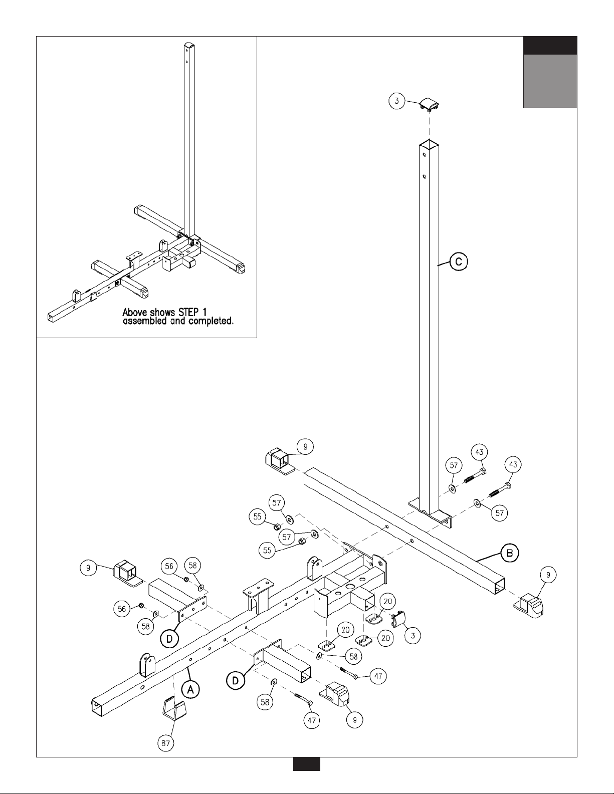
Be careful to assemble all components
in the sequence they are presented.
NOTE:
Finger tighten all hardware in this step. Do Not
A. Insert two Foot Caps (9) into the ends of Rear Base Frame (B). Insert Convex End Cap (3) to
the top of Rear Vertical Frame (C).
B. Attach Main Base Frame (A) to Rear Base Frame (B) and Rear Vertical Frame (C) using:
Two 52 (1/2” x 3 1/2” hex head bolt)
Four 57 (1/2” washer)
Two 55 (1/2” nylon lock nut)
C. Insert two Foot Caps (9) to the ends of Side Base Frame (D).
D. Attach two Side Base Frames (D) to Main Base Frame (A) using:
Two 47 (3/8” x 3” hex head bolt)
Four 58 (3/8” washer)
Two 56 (3/8” nylon lock nut)
wrench tighten until end of step 7.
E. Insert Weight Stack Shim (20) to Main Base Frame (A).
Connect Frame Leveler (87) to Main Base Frame (A).
Insert Convex End Cap (3) to the side of Main Base Frame (A) as shown.
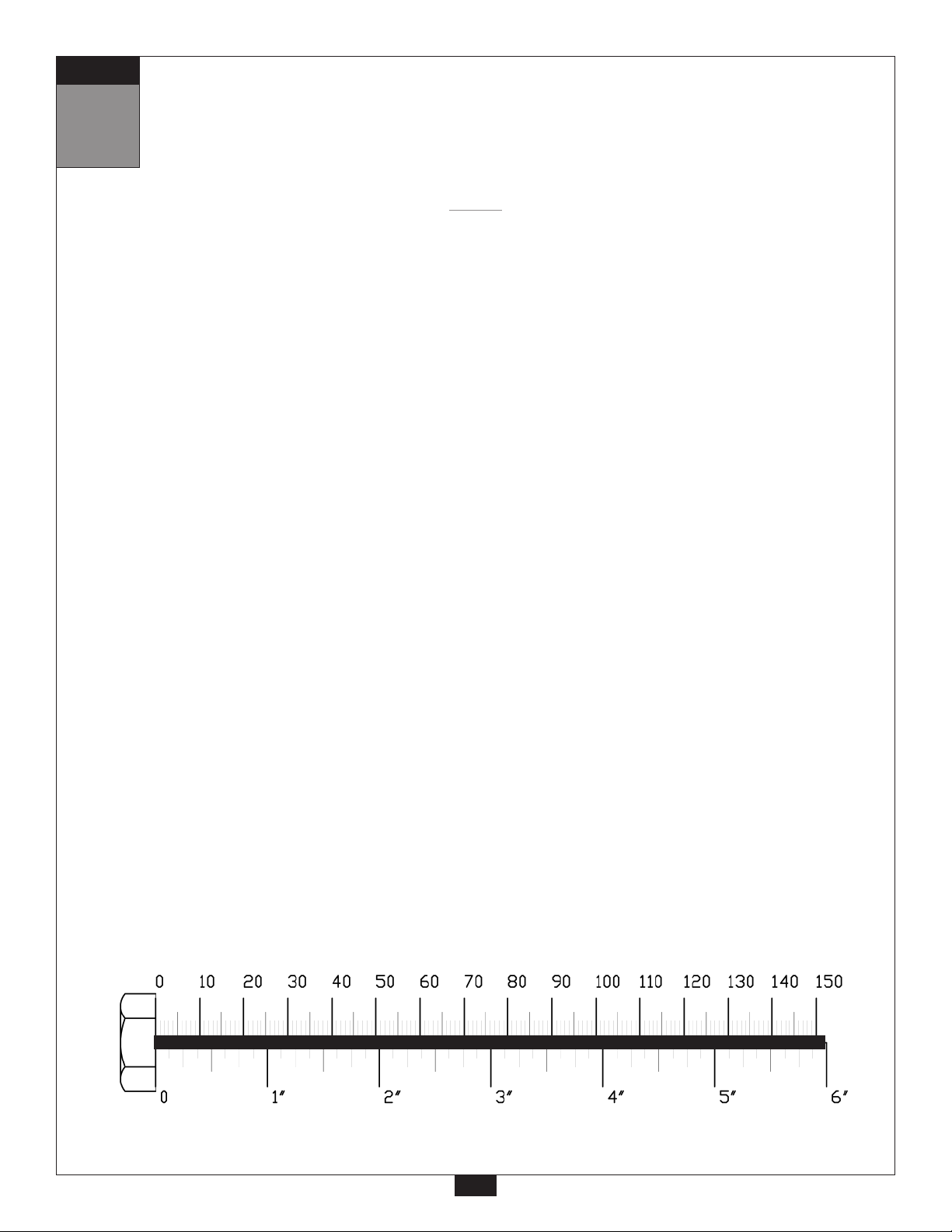
mm
Inch
2
STEP
1
3
STEP
2
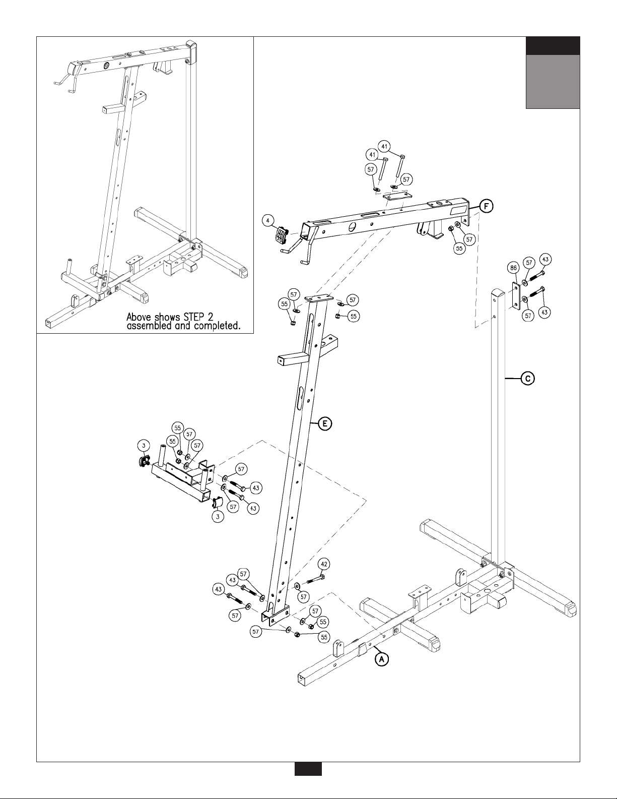
Be careful to assemble all components
in the sequence they are presented.
NOTE:
Finger tighten all hardware in this step. Do Not
A. Attach Angled Support Frame (E) to Main Base Frame (A) using:
Two 43 (1/2” x 3 1/4” hex head bolt)
Four 57 (1/2” washer)
Two 55 (1/2” nylon lock nut)
B. Insert Convex End Cap (4) to the front of the Top Frame (F).
Attach Top Frame (F) and Plate (86) to the Rear Vertical Frame (C) using:
Two 43 (1/2” x 3 1/4” hex head bolt)*
Three 57 (1/2” washer)
One 55 (1/2” nylon lock nut)
*NOTE:
The top bolt (43) goes into an internally threaded nut inside the Top Frame (F).
C. Attach Top Frame (F) and Plate (86) to Angled Support Frame (E) using:
Two 41 (1/2” x 4 1/4” hex head bolt)
Four 57 (1/2” washer)
Two 55 (1/2” nylon lock nut)
wrench tighten until end of step 7.
D. Attach Pec Dec Frame (G) to Angled Support Frame (E) in the bottom two holes as shown using:
One 42 (1/2” x 3 3/4” hex head bolt)
Two 43 (1/2” x 3 1/4” hex head bolt)
Five 57 (1/2” washer)
Two 55 (1/2” nylon lock nut)
Attach two Curved End Caps (3) to Pec Dec Frame (G) as shown.
mm
Inch
4
STEP
2
5
STEP
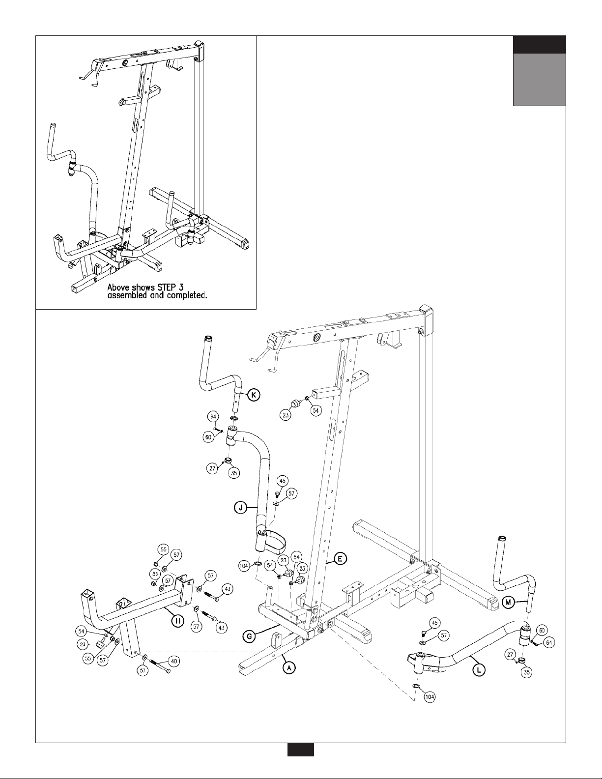
3
Be careful to assemble all components
in the sequence they are presented.
NOTE:
Finger tighten all hardware in this step. Do Not
A. Above the Pec Dec Frame (G) connect the Leg Extension Frame (H) to Angled Support
Frame (E) using:
Two 43 (1/2” x 3 1/4” hex head bolt)
Four 57 (1/2” washer)
Two 55 (1/2” nylon lock nut)
B. Attach the Leg Extension Frame (H) to Main Base Frame (A) using:
One 40 (1/2” x 5 1/2” hex head bolt)
Two 57 (1/2” washer)
One 55 (1/2” nylon lock nut)
C. Attach Left Pec Dec Arm (J) to Pec Dec Frame (G) using:
One 45 (1/2” x 3/4” hex head bolt)
One 57 (1/2” washer)
Attach Left Pec Dec Handle (K) to Left Pec Dec Arm (J) using:
One 64 (5/16” x 3/4” round allen head bolt)
One 60 (5/16” spring lock washer)
wrench tighten until end of step 7.
D. Attach Right Pec Dec Arm (L) to Pec Dec Frame (G) using:
One 45 (1/2” x 3/4” hex head bolt)
One 57 (1/2” washer)
Attach Right Pec Dec Handle (M) to Right Pec Dec Arm (L):
One 64 (5/16” x 3/4” hex head bolt)
One 60 (5/16” spring lock washer)
E. Attach two Chrome Round End Cap (34) to the top of the Left Pec Dec Handle (K) and one to the
top of the Right Pec Dec Handle (M) as shown, and tighten Allen Screw (67).
Attach two Chrome Collars (35) one to the bottom of the Left Pec Dec Handle (K) and one to the
bottom of the Right Pec Dec Handle (M) as shown, and tighten Allen Screw (27).
F. Attach one Rubber Stop (23) to the front of Leg Extension Frame (H).
Attach two Rubber Stops (23) to the Pec Dec Frame (G).
Attach one Rubber Stop (23) to the horizontal pillar sticking out of the Angled Support Frame (E)
as shown.
mm
Inch
6
STEP
3
7
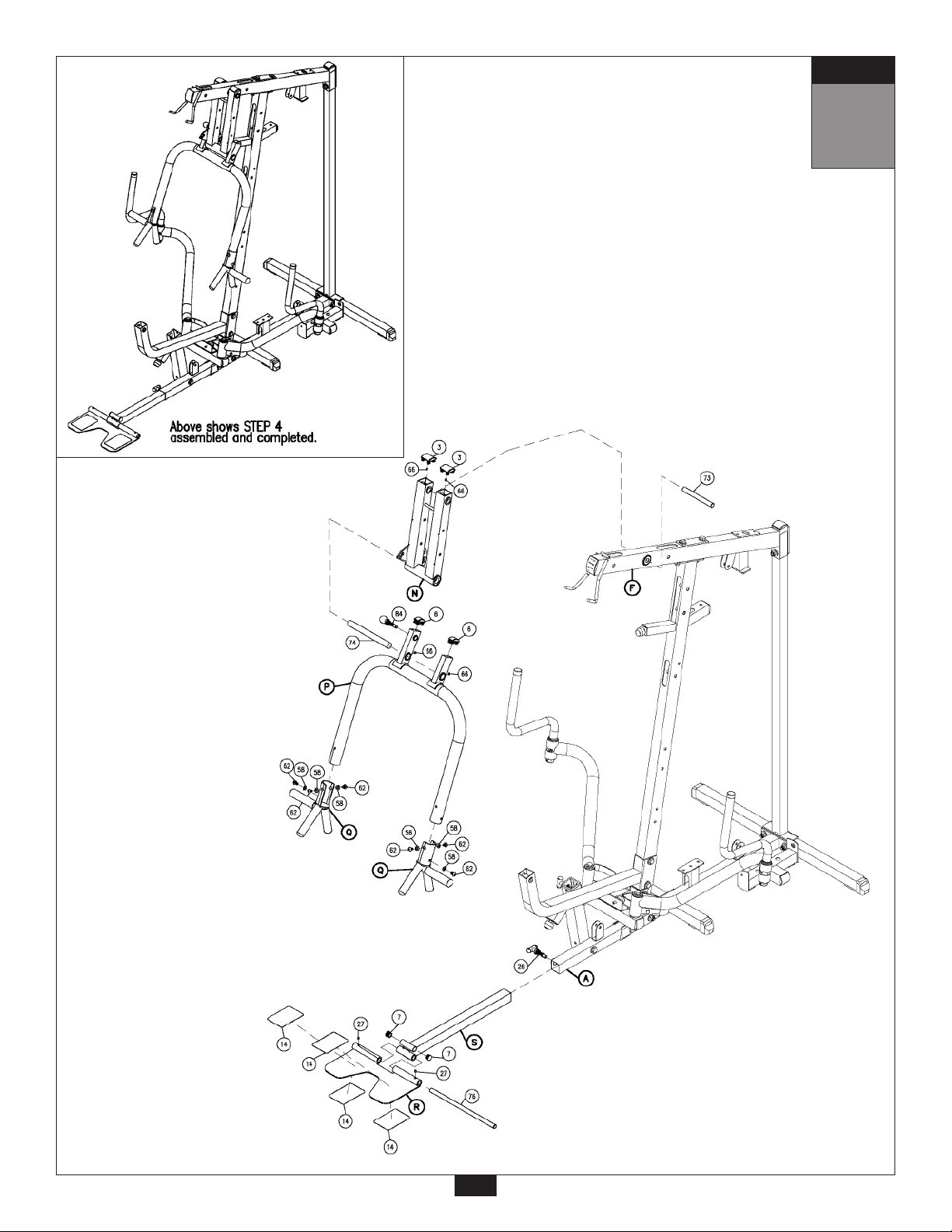
STEP
4
Be careful to assemble all components
in the sequence they are presented.
NOTE:
Finger tighten all hardware in this step. Do Not
A. Attach two Convex End Caps (3) to the top of Seated Press Arm Support (N).
Attach Seated Press Arm Support (N) to Top Frame (F) using Shaft (73), and tighten
Allen Screw (66).
B. Attach Seated Press Arm (P) to Seated Press Arm Support (N) using Shaft (74), and tighten
Allen Screw (66).
Attach two 1” X 2” Convex End Caps (6) to the top of the Seated Press Arm (P).
C. Attach two Seated Press Handles (Q) to Seated Press Arm (P) using:
Six 62 (3/8” x 5/8” flat allen head bolt)
Six 92 (3/8” bent lock washer)
Foam Grip (83) and Round End Cap (16) are preinstalled.
D. Attach Foot Plate (R) to Adjustable Chrome Frame (S) with Shaft (76) and tighten Allen Screw (27).
wrench tighten until end of step 7.
E. Slide Adjustable Chrome Frame (S) into Main Base Frame (A) and hold in place with T-Shaped
Pop Pin (26).
Slide two Round End Caps (7) into the openings on the top of the Adjustable Chrome Frame (S)
as shown.
mm
Inch
8
STEP
4
9
STEP
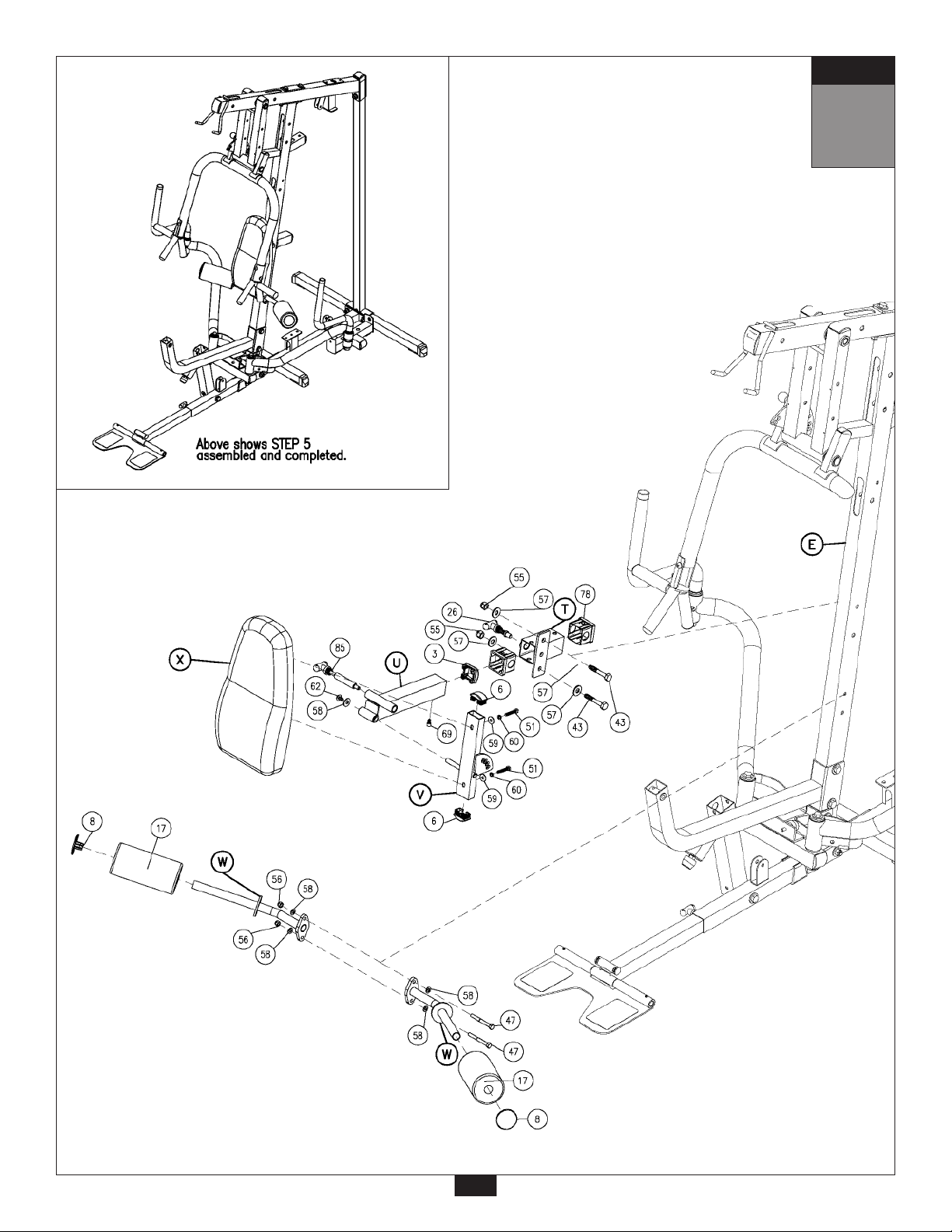
5
Be careful to assemble all components
in the sequence they are presented.
NOTE:
Finger tighten all hardware in this step. Do Not
A. Slide two Plastic Bushings (78) into Back Pad Holder (T) as shown.
Attach Back Pad Holder (T) To Angled Support Frame (E) using:
Two 43 (1/2” x 3 1/4” hex head bolt)
Four 57 (1/2” washer)
Two 55 (1/2” nylon lock nut)
B. Slide Convex End Cap (3) into Chrome Back Pad Frame (U) as shown.
Slide Chrome Back Pad Frame (U) into Back Pad Holder (T) and hold in place with
T-Shaped Pop Pin (26).
C. Slide two 1” X 2” Convex End Caps (6) into Back Pad Frame (V) as shown.
Attach Back Pad Frame (V) to Chrome Back Pad Frame (U) as shown with a T-Shaped
Pop Pin (85), and using:
One 62 (3/8” x 5/8” allen bolt)
One 58 (3/8” washer)
wrench tighten until end of step 7.
D. Attach two Leg Hold Downs (W) to the Angled Support Frame (E) using:
Two 53 (3/8” x 3 1/4” hex head bolt)
Four 58 (3/8” washer)
Two 56 (3/8” nylon lock nut)
C. Attach two Foam Rollers (17) onto Leg Hold Downs (W) and hold in place with two Roller End
Caps (8) as shown.
F. Attach Back Pad (X) to Back Pad Frame (V) using:
Two 51 (5/16” x 1 3/4” hex head bolt)
Two 60 (5/16” spring lock washer)
Two 59 (5/16” washer)
G. Insert Flat Allen Head Bolt (69) into Chrome Back Pad Frame (U), this will help hold the Chrome
Back Pad Frame (U) in place.
mm
Inch
10
STEP
5
11
STEP
6
Be careful to assemble all components
in the sequence they are presented.
NOTE:
Finger tighten all hardware in this step. Do Not
A. Attach two Convex End Caps (3), one to the top and one to the bottom, of Leg Extension Arm (Y).
Attach Leg Extension Arm (Y) to Leg Extension Frame (H) using pre-installed Shaft (77) as
shown. Tighten the two Allen Screws (27) to lock down Shaft (77) in Leg Extension Frame (H).
Attach Convex End Cap (3) to the front of Leg Extension Frame (H) as shown.
B. Attach Leg Extension Pad Holder (Z) to Leg Extension Arm (Y) using:
One 43 (1/2” x 3 1/4” hex head bolt)
Two 57 (1/2” washer)
One 55 (1/2” nylon lock nut)
C. Attach the two Leg Pads (ZA) to Leg Extension Pad Holder (Z) using:
Four 94 (5/16” x 3/4” hex head bolt)
Four 60 (5/16” spring lock washer)
Four 59 (5/16” washer)
wrench tighten until end of step 7.
D. Attach two 1” X 2” Curved End Caps (6) to the front and back of the Leg Extension Seat Pad
Frame (ZC) as shown.
Attach Leg Extension Seat Pad (ZB) to Leg Extension Seat Pad Frame (ZC) using:
Two 51 (5/16” x 1 3/4” hex head bolt)
Two 60 (5/16” spring lock washer)
Two 59 (5/16” washer)
E. Slide Plastic Bushing (79) into Leg Extension Frame (H) as shown.
Attach Hydraulic Seat Adjuster (88) to the bottom and inside the receptacle in the Leg Extension
Frame (H) using:
One 47 (3/8” x 3” hex head bolt)
Two 58 (3/8” washer)
One 56 (3/8” nylon lock nut)
F. Slide Leg Extension Seat Pad Frame (ZC) into Plastic Bushing (79) in Leg Extension Frame (H)
and attach to the top of Hydraulic Seat Adjuster (88) using:
One 48 (3/8” x 2 3/4”hex head bolt)
Two 58 (3/8” washer)
One 56 (3/8” nylon lock nut)
Insert T-Shaped Pop Pin (26) into the threaded opening in the Leg Extension Frame (H).
G. Attach Foam Roller Bar (75) to the front of the Leg Extension Seat Pad Frame (ZC) as shown.
Slide Foam Rollers (17) onto Foam Roller Bar (75). Hold in place with 3” Plastic Washer (21), on
the inside, and Roller End Caps (8) on the outside.
mm
Inch
12
 Loading...