

Body Solid Fusion 400 Owner's Manual
Assembly Instructions
OWNER’S MANUAL
&

Total Body Workout DVD
2
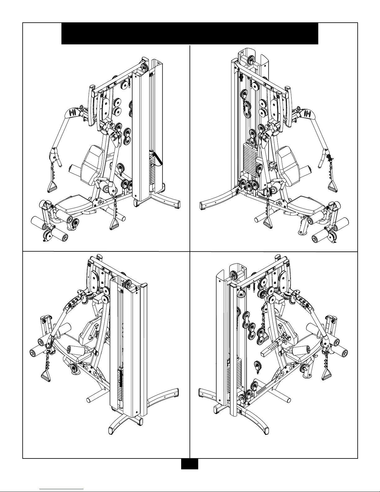
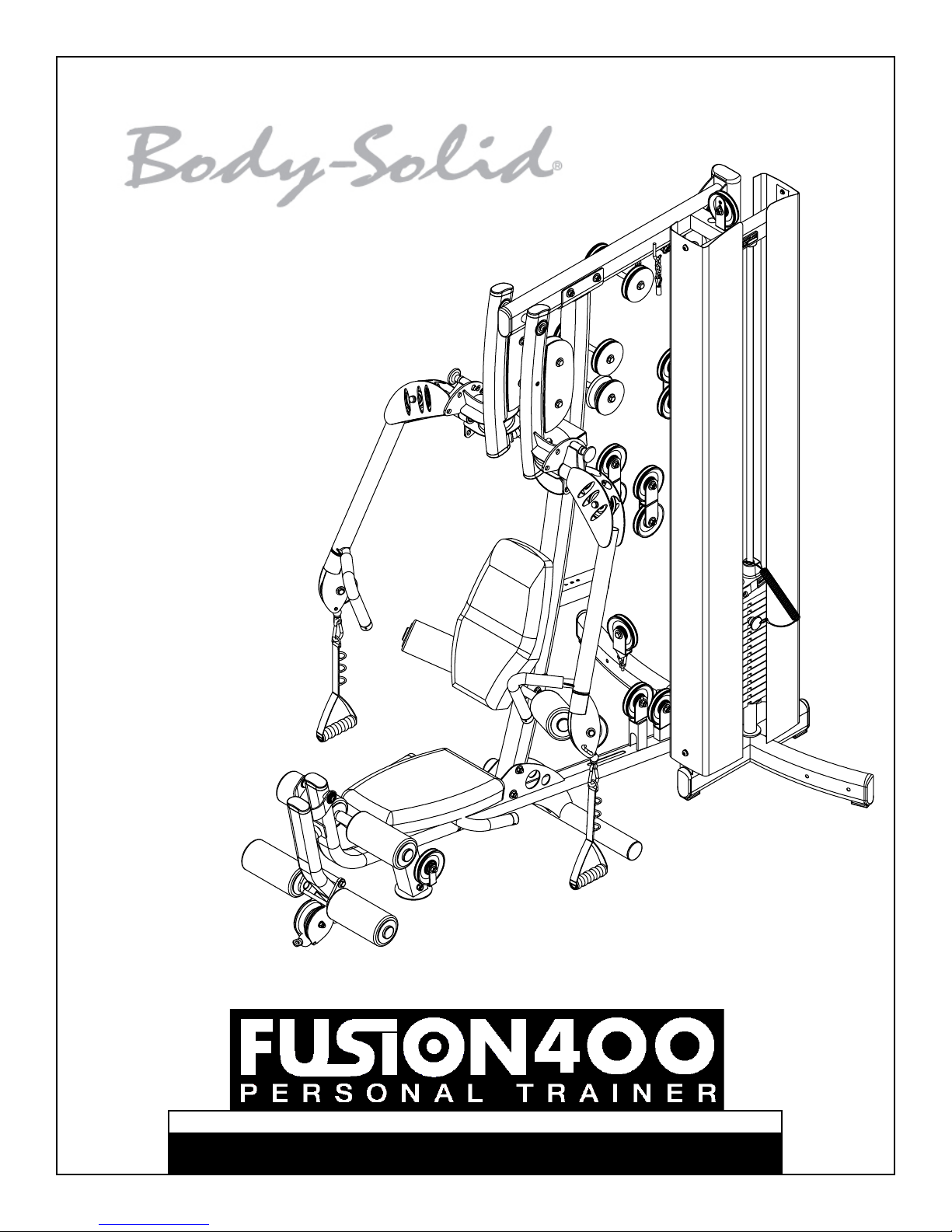
Fusion 400
Reference Drawings
Note: Due to continuing product improvements, specifi cations and designs are subject to change
without notice.
Even though we have prepared this manual with extreme care, neither the publisher nor the
author can accept responsibility for any errors in, or omission from, the information given.
3

Important Safety Instructions
B e fore beginning any fi tness program, you should obtain a complete physical examination from your physician.
Il est conseille de subir un examen medical complet avant d’entreprendre tout programme d’exercise. Si vous
avez des etourdissements ou des faiblesses, arretez les exercices immediatement.
Antes de comenzar cualquier programma de ejercicios, deberias tener un examen fi sico con su doctor.
When using exercise equipment, you
should always take basic precautions,
including the following:
• Read all instructions before using the Fusion 400. These
instructions are written to ensure your safety and to
protect the unit.
• Do not allow children on or near the equipment.
• Use the equipment only for its intended purpose as
described in this guide. Do not use accessory
attachments that are not recommended by the
manufacturer. Such attachments might cause injuries.
• Wear proper exercise clothing and shoes for your
workout, no loose clothing.
• Use care when getting on or off the unit.
• Do not overexert yourself or work to exhaustion.
• If you feel any pain or abnormal symptoms, stop your
workout immediately and consult your physician.
• Never operate unit when it has been dropped or
damaged. Return the equipment to a service center
for examination and repair.
• Never drop or insert objects into any opening in the
equipment.
• Always check the unit and its cables before each
use. Make sure that all fasteners and cables are
secure and in good working condition.
• Do not use the equipment outdoors or near water.
The Fusion 400 is designed for your enjoyment. By
following these precautions and using common
sense, you will have many safe and pleasurable hours
of healthful exercise with your Body-Solid Fusion 400.
After assembly, you should check all functions to
ensure correct operation. If you experience problems,
fi r st recheck the assembly instructions to locate any
possible errors made during assembly. If you are unable
to correct the problem, call the dealer from whom
you purchased the machine or call 1-800-556-3113
for the dealer nearest you.
Obtaining Service
Please use this Owner’s Manual to make sure that all
parts have been included in your shipment. When
ordering parts, you must use the part number and
description from this Owner’s Manual. Use only
Body-Solid replacement parts when servicing this
machine. Failure to do so will void your warranty and
could result in personal injury.
For information about product operation or service,
check out the offi cial Body-Solid website at
www.bodysolid.com or contact an authorized
Body-Solid dealer or a Body-Solid factory-authorized
service company or contact Body-Solid customer
service at one of the following:
Personal Safety During Assembly
• It is strongly recommended that a qualifi ed dealer
assemble the equipment. Assistance is required.
• Before beginning assembly, please take the time to
read the instructions thoroughly.
• Read each step in the assembly instructions and
follow the steps in sequence. Do not skip ahead. If
you skip ahead, you may learn later that you have to
disassemble components and that you may have
damaged the equipment.
• Assemble and operate the Fusion 400 on a solid, level
surface. Locate the unit a few feet from the walls or
furniture to provide easy access.
To ll Free: 1-800-556-3113
Phone: 1-708-427-3555
Fax: 1-708-427-3598
E-mail: service@bodysolid.com
Or write to: Body-Solid, Inc.
Service Department
1900 S. Des Plaines Ave.
Forest Park, IL 60130 USA
Retain this Owner’s Manual for future
reference. Part numbers are required when
ordering parts.
4
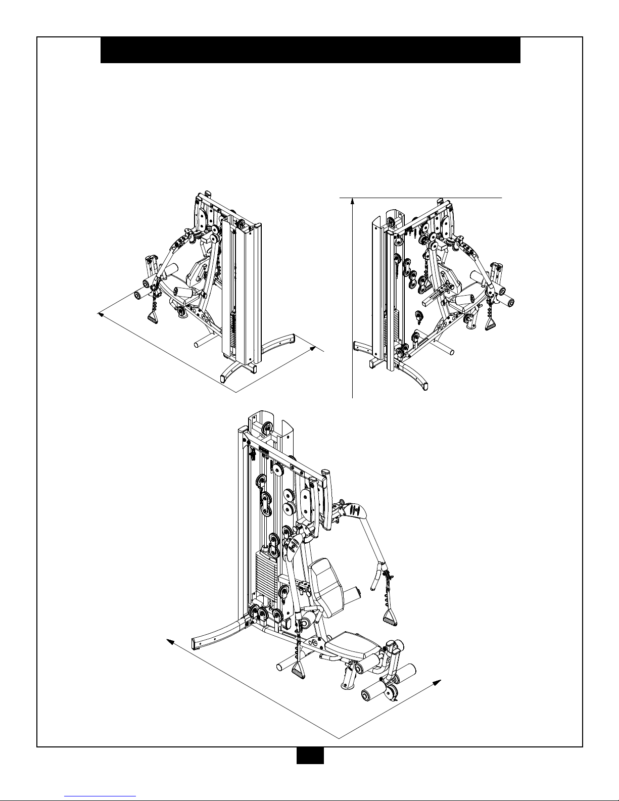
Dimensions
1950mm
6' 4"
1184mm
3' 10"
Dimensions
Height
1950mm
6' 8"
3048mm
10'
1829mm
6'
Suggested usage space
The room layout diagram below will help you decide the best placement for your Fusion 400.
The dimensions of the Fusion 400 are: width 3’ 10” X length 6’ 4”.
The ceiling height requirement for the Fusion 400 is 6’ 8”.
The usage space is: width 6’ X length 10’ (The usage space is the overall space needed for operation.)
The usage space needed for the Fusion 400 could be more, depending on the user, allow enough room for the
Low Row Station.
5

Safety Guidelines
Successful resistance training programs have one prominent feature in common...safety. Resistance
training has some inherent dangers, as do all physical activities. The chance of injury can be greatly
reduced or completely removed by using correct lifting techniques, proper breathing, maintaining
equipment in good working condition, and by wearing the appropriate clothing.
1. It is highly recommended that you consult your physician before beginning any exercise
program. This is especially important for individuals over the age of 35, or persons with
pre-existing health problems.
2. Always warm up before starting a workout. Try to do a total body warm up before you start. It is
especially important to warm up the specifi c muscle groups you are going to be using. This can
be as simple as performing a warm up set of high repetitions and light weight for each exercise.
3. Use proper form. Focus on only working the muscle groups intended for the exercise you are
doing. If there is strain elsewhere, you may need to re-evaluate the amount of weight that is
involved with the lift. Keeping proper form also includes maintaining control through an entire
range of motion.
4. Breath properly. Inhale during the eccentric phase of the exercise, and exhale during the lifting,
or concentric phase. Never hold your breath during any part of an exercise.
5. Always wear the appropriate clothing and shoes when exercising. Wearing comfortable athletic
shoes with good support and loose fi tting, breathable clothing will reduce the risk of injury.
6. Maintaining equipment in proper operating condition is of utmost importance for a safe
resistance training program. Pulleys and cables should be checked for wear frequently and
replaced as needed. Equipment should be lubricated as indicated by the manufacturer.
7. Read and study all warning labels on this machine. It is absolutely necessary that you
familiarize yourself and all others with the proper operation of this machine prior to use.
8. Keep hands, limbs, loose clothing and long hair well out of the way of all moving parts.
9. Do not attempt to lift more weight than you can control safely.
10. Inspect the machine daily for loose or worn parts. If a problem is found do not allow the
machine to be used until all parts are tightened or worn or defective parts are repaired or
replaced.
6
Assembly Instructions
Assembly of the Fusion 400 takes professional installers about 3 hours to complete. If this is the fi rst
time you have assembled this type of equipment, plan on signifi cantly more time.
PROFESSIONAL INSTALLERS ARE HIGHLY RECOMMENDED!
However, if you acquire the appropriate tools, obtain assistance, and follow the assembly steps sequentially, the process will take time, but is fairly easy.
Assembly Tips
Read all “Notes” on each page before beginning each
step.
While you may be able to assemble the Fusion 400 using
the illustrations only, important safety notes and other tips
are included in the text.
Some pieces may have extra holes that you will not use.
Use only those holes indicated in the instructions and illustrations.
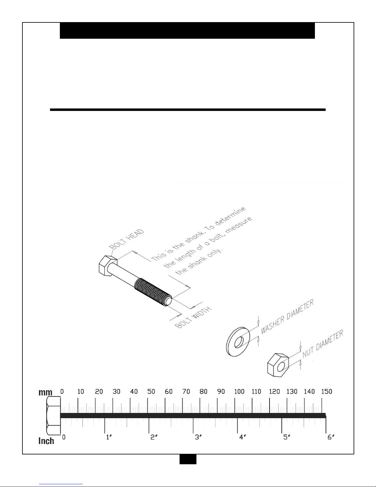
NOTE: To fi nd out the length of a particular bolt, measure
its shank (the long, narrow part beneath the head).
Refer to the following diagram:
Do not fully tighten bolts until instructed to do so.
Note: After assembly, you should check all functions to ensure
correct operation. If you experience problems, fi rst recheck
the assembly instructions to locate any possible errors made
during assembly.
If you are unable to correct the problem, call the dealer from
whom you purchased the machine or call 1-800-556-3113
for the dealer nearest you.
7

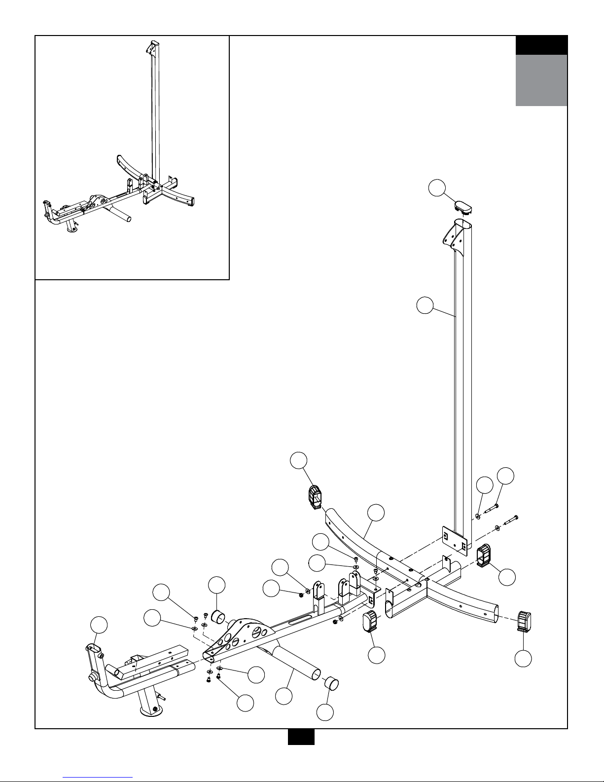
STEP
A. Slide Main Base Frame (A) into Main Base Frame (B) and connect using:
Four 68 (M10x15 allen head bolt)
Four 79 (M10 washer)
B. Insert Round End Caps (33) into Main Base Frame (B).
C. Attach Main Base Frame (B) and Rear Upright Frame (D) to Press Arm Pivot (C) by using:
Two 62 (M10x75 partial thread hex head bolt)
Four 79 (M10 washer)
Two 84 (M10 nylon lock nut)
D. Insert Round End Caps (38) into Press Arm Pivot (C).
E. Insert Convex End Cap (37) into Rear Upright Frame (D).
1
Be careful to assemble all components
in the sequence they are presented.
NOTE:
Finger tighten all hardware in this step. Do Not wrench tighten until end of step 13.
Two 68 (M10x15 allen head bolt)
Two 79 (M10 washer)
D. Insert Round End Caps (38) into Press Arm Pivot (C).
E. Insert Convex End Cap (37) into Rear Upright Frame (D).
8
Above shows STEP
assembled and completed
1
37
D
62
79
38
84
33
A
C
B
33
38
38
38
79
68
79
79
68
68
79
Above shows STEP
assembled and completed
1
STEP
1
9

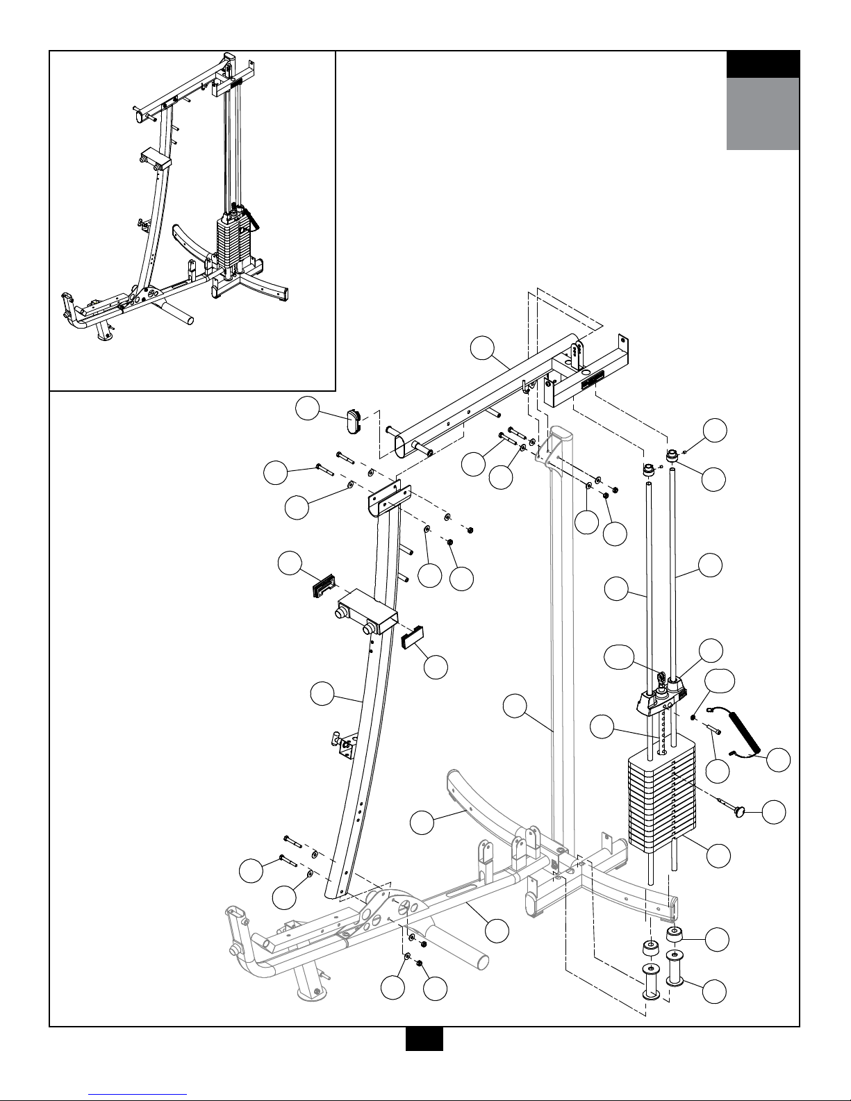
STEP
A. Connect Main Front Frame (F) to Main Base Frame (B) by using:
Two 62 (M10x75 partial thread hex head bolt)
Four 79 (M10 washer)
Two 84 (M10 nylon lock nut)
B. Insert Flat End Caps (27) into Main Front Frame (F).
C. Connect Main Top Frame (E) to Main Front Frame (F) by using:
Two 62 (M10x75 partial thread hex head bolt)
Four 79 (M10 washer)
Two 84 (M10 nylon lock nut)
D. Connect Main Top Frame (E) to Rear Upright Frame (D) by using:
Two 62 (M10x75 partial thread hex head bolt)
Four 79 (M10 washer)
Two 84 (M10 nylon lock nut)
E. Insert Convex End Cap (37) into Main Top Frame (E).
F. Slide Chrome Guide Rod (Y) through Rubber Donut (43), Weight Stack Risers (G) and
Press Arm Pivot (C) as shown in the diagram.
G. Load Weight Plates (44) onto Chrome Guide Rod (Y) one at a time.
H. Connect Selector Rod (88) to Top Plate (21) using:
One 70 (3/8"x2" partial thread socket head bolt)
One 108 (spring lock washer)
I. Connect Selector Rod Top Bolt (102), Jam Nut (103), Spring Lock Washer(104) to Selector Rod (88).
J. Secure Chrome Guide Rod (Y) to Main Top Frame (E) by using:
Two 76 (M8x8 allen screw)
Two 31 (shaft collar)
2
Be careful to assemble all components
in the sequence they are presented.
NOTE:
Finger tighten all hardware in this step. Do Not wrench tighten until end of step 13.
10
STEP
2
E
31
76
21
102
57
56
70
43
84
79
62
79
F
27
37
84
79
62
79
Y
Y
27
44
G
108
62
79
79
84
88
D
C
B
Above shows STEP
assembled and completed
2
2
11

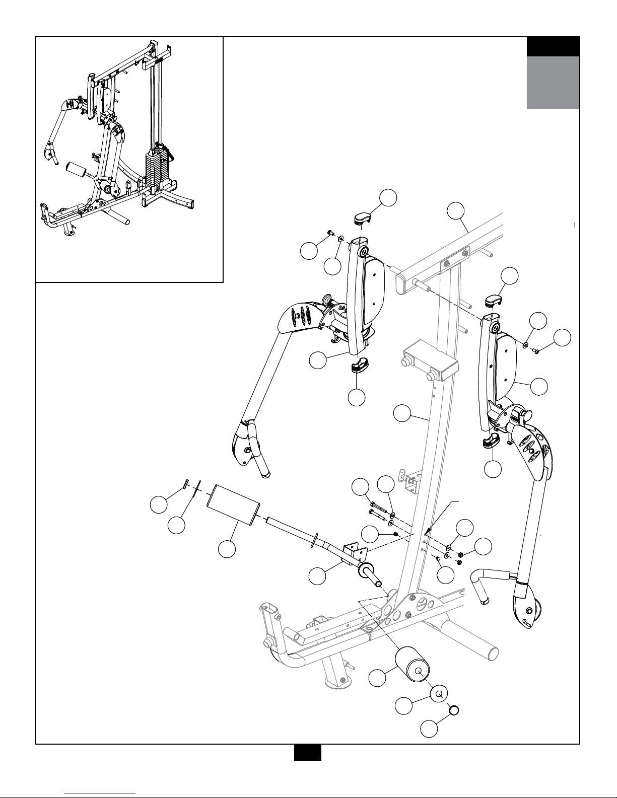
STEP
A. Attach Leg Hold Down Frame (P) to Main Front Frame (F) by using:
Two 62 (M10x75 partial thread hex head bolt)
Four 79 (M10 washer)
Two 84 (M10 nylon lock nut)
NOTE 1:
The position of Leg Hold Down Frame (P) may be adjusted in a higher or lowerposition depending
on the user's needs. Cover unused holes with Round End Cap (29) as shown in the diagram.
B. Slide Foam Roller (22), Nylon Washer (40) and Roller End Cap (23) to
the ends of Leg Hold Down Frame (P) as shown in the diagram.
C. Connect Left Functional Training Arm (J) and Right Functional Training Arm (H) to
Main Top Frame (E) as shown by using:
Two 69 (M10x20 allen head bolt)
Two 79 (M10 washer)
D. Insert Convex End Caps (36) to Left Functional Training Arm (J) and Right Functional Training Arm (H).
3
Be careful to assemble all components
in the sequence they are presented.
NOTE:
Finger tighten all hardware in this step. Do Not wrench tighten until end of step 13.
12
STEP
Above shows STEP
assembled and completed
)
3
36
J
69
62
79
29
23
40
22
P
84
79
H
79
36
36
36
79
69
22
40
E
F
29
23
NOTE 1
Above shows STEP
assembled and completed
3
3
13

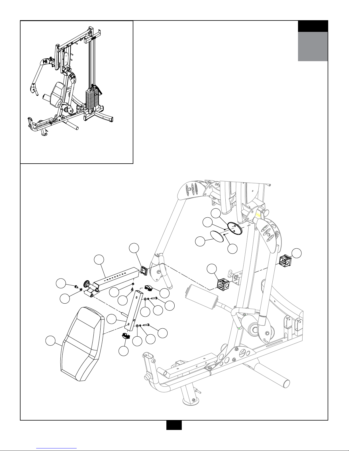
STEP
A. Insert Pulley Holder With Stop (Q) into Nylon Bushing (30) as shown in the diagram.
B. Insert Flat End Cap (26) into Pulley Holder With Stop (Q).
C. Secure Pulley Holder With Stop (Q) by installing:
One 75 (M8x10 partial thread socket head bolt)
One 82 (M8 spring lock washer)
D. Connect Pivoting Back Rest Frame (R) to Pulley Holder With Stop (Q) by using:
One 68 (M10x15 allen head bolt)
One 80 (M10 washer)
E. Insert Flat End Caps (35) into Pivoting Back Rest Frame (R).
F. Connect Back Pad (98) to Pivoting Back Rest Frame (R) by using:
Two 73 (M8x45 allen head bolt)
Two 82 (M8 spring lock washer)
Two 81 (M8 washer)
G. Install Nameplate Seat (39) to the F400 by using:
Two 89 (M5x10 tapered crosshead screw)
Apply Nameplate (45) to Nameplate Seat (39) after secured.
4
Be careful to assemble all components
in the sequence they are presented.
NOTE:
Finger tighten all hardware in this step. Do Not wrench tighten until end of step 13.
14
STEP
Above shows STEP
assembled and completed
4
Q
98
68
80
35
30
R
73
82
81
39
45
26
75
73
82
81
30
89
89
35
82
4
15

STEP
A. Connect both Armrest (S) to Main Base Frame (B) using:
Two 61 (M10x85 partial thread hex head bolt)
Four 80 (M10 washer)
Two 84 (M10 nylon lock nut)
B. Insert Flat End Cap (34) into Main Base Frame (B) as shown.
C. Connect Seat Pad (97) to Main Base Frame (B) by using:
Two 72 (M8x50 allen head bolt)
Two 82 (M8 spring lock washer)
Two 81 (M8 washer)
D. Slide Foam Roller Shaft (T) through Main Base Frame (B) as shown in the diagram
and insert Foam Rollers (22), Nylon Washer (40) and Roller End Cap (23).
5
Be careful to assemble all components
in the sequence they are presented.
NOTE:
Finger tighten all hardware in this step. Do Not wrench tighten until end of step 13.
16
STEP
Above shows STEP
assembled and completed
5
34
97
23
40
22
40
T
40
22
40
23
72
82
81
72
82
81
80
84
S
61
80
S
B
5
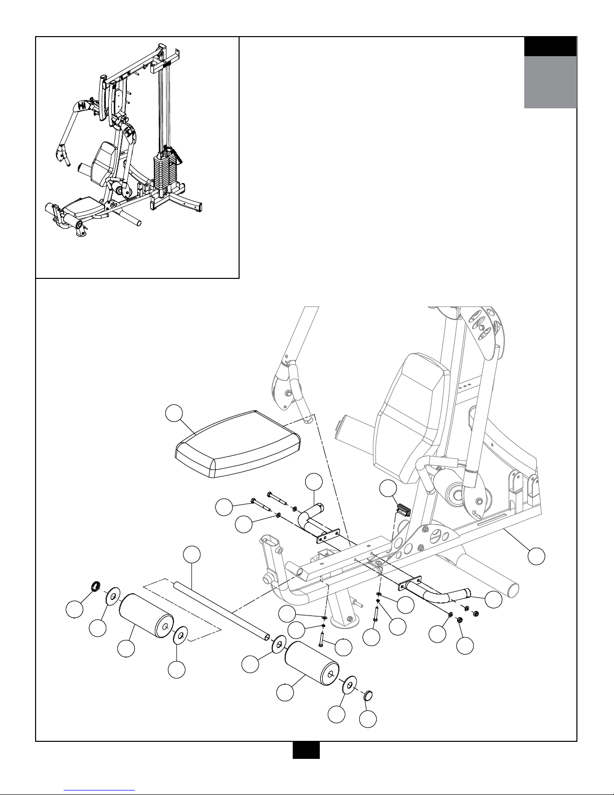
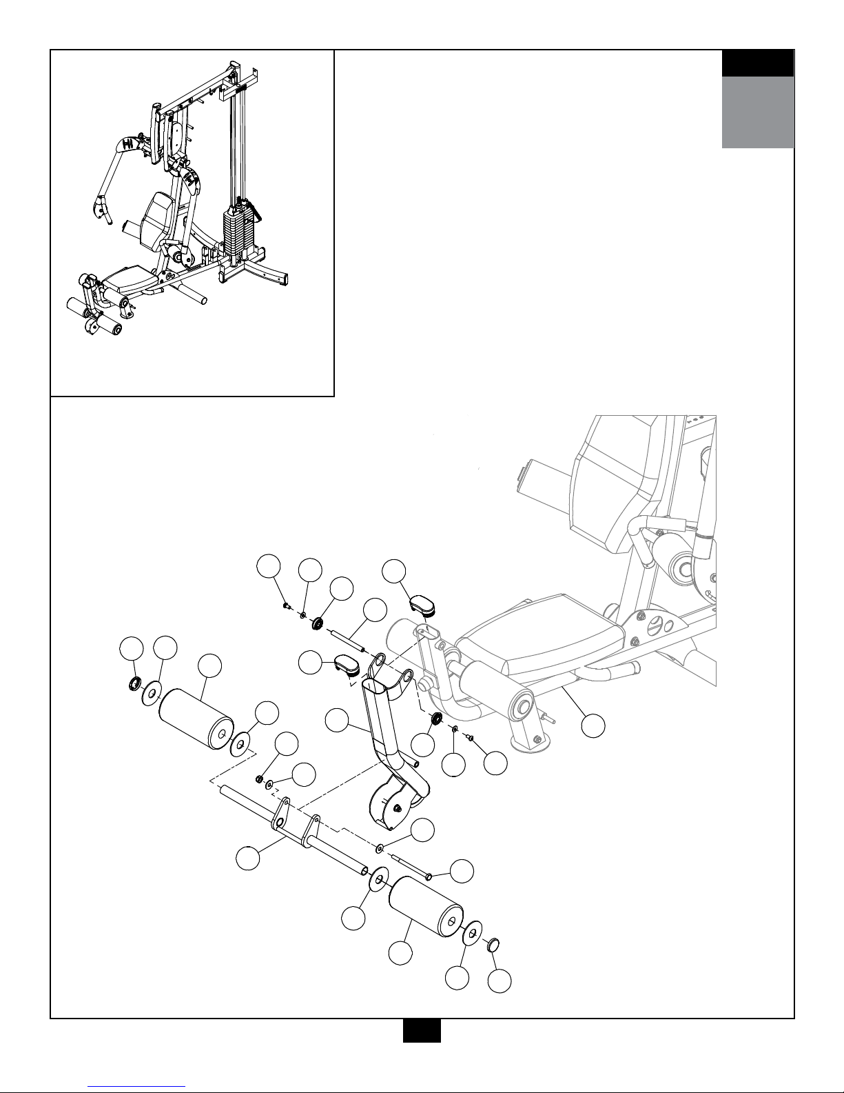
17

STEP
A. Connect Leg Extension Arm (U) to Main Base Frame (B) using:
One 1 (shaft)
Two 6 (bearing)
Two 81 (M8 washer)
Two 74 (M8x15 allen head bolt)
B. Insert Convex End Cap (36) into Leg Extension Arm (U) and Main Base Frame (B) as shown in the diagram.
C. Connect Pivoting Roller Frame (V) to Leg Extension Arm (U) using:
One 60 (M10x140 partial thread hex head bolt)
Two 79 (M10 washer)
One 84 (M10 nylon lock nut)
D. Slide Foam Rollers (22) onto Pivoting Roller Frame (V) and secure using:
Four 40 (nylon washers)
Two 23 (roller end cap)
6
Be careful to assemble all components
in the sequence they are presented.
NOTE:
Finger tighten all hardware in this step. Do Not wrench tighten until end of step 13.
18
STEP
Above shows STEP
assembled and completed
6
36
74
81
6
1
36
6
81
74
23
40
22
40
V
84
79
40
22
40
23
79
60
U
B
6
19

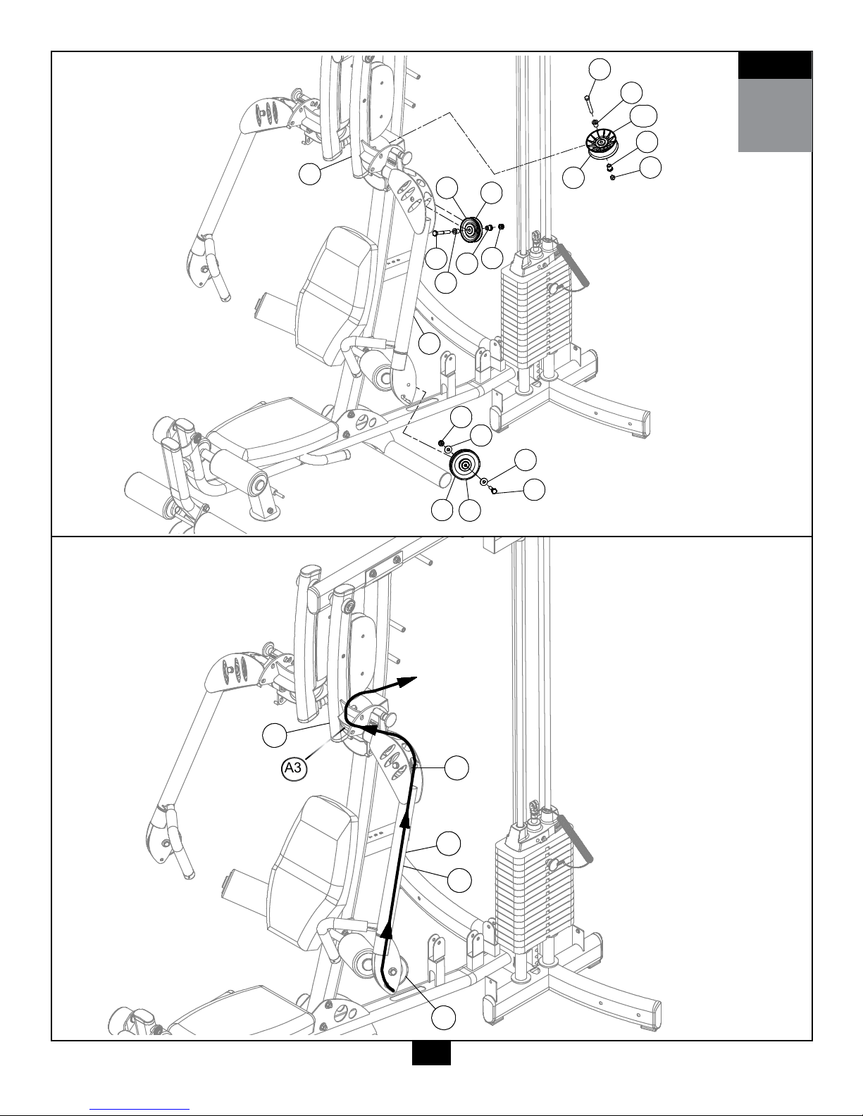
STEP
A. Insert Pulley (A1) into Functional Training Arm (L) as shown using:
One 66 (M10x45 partial thread hex head bolt)
Two 79 (M10 washer)
One 84 (M10 nylon lock nut)
B. Insert Pulley (A2) into Functional Training Arm (L) as shown using:
One 62 (M10x75 partial thread hex head bolt)
Two 6 (bearing)
One 84 (M10 nylon lock nut)
C. Insert Pulley (A3) into Functional Training Arm (H) by using:
One 71 (3/8"x75 allen head bolt)
Two 83 (3/8" washer)
One 86 (3/8" nylon lock nut)
D. Route Functional Training Arm Cable (55) from Pulley (A1) up Functional Training Arm (L) and
around Pulley (A2) as shown in Diagram 2. Please leave Functional Training Arm Cable (55) hang until Step 8B.
7
Be careful to assemble all components
in the sequence they are presented.
NOTE:
Finger tighten all hardware in this step. Do Not wrench tighten until end of step 13.
20
S T
84
79
50
79
66
62
6
A2
6
84
86
71
A1
50
H
L
Diagram 1
Pulley installation
7B
6
6
A3
118
L
A1
A2
H
Diagram 2
Cable installation
55
Diagram 1
Diagram 1
Pulley Installation
Pulley Installation
STEP
7
Diagram 2
Cable Installation
A3
21

STEP
A. Install Pulley (A7) and Pulley (A5) as shown in Diagram 1 by using:
Two 66 (M10x45 partial thread hex head bolt)
Four 79 (M10 washer)
Two 84 (M10 nylon lock nut)
B. Install Pulley (A6) as shown in Diagram 1 by using:
One 66 (M10x45 partial thread hex head bolt)
One 79 (M10 washer)
One 19 (plate)
C. Install Pulley (A4) as shown in Diagram 1 by using:
One 62 (M10x75 partial thread hex head bolt)
One 79 (M10 washer)
One 19 (plate)
D. Install Pulley (A8) as shown in Diagram 1 by using:
One 66 (M10x45 partial thread hex head bolt)
One 79 (M10 washer)
One 19 (plate)
E. Connect Pulley (A9) to Holder for Double Crossed Pulleys (W) by using:
One 66 (M10x45 partial thread hex head bolt)
One 79 (M10 washer)
One 84 (M10 nylon lock nut)
F. Bring Functional Training Arm Cable (55) up and around Pulley (A4), Pulley (A5),
Pulley (A6), Pulley (A7) and Pulley (A8) then down towards Pulley (A9) as shown in Diagram 2.
G. Route cable up from Pulley (A9) and terminate on the chain hook provided on Main Top Frame (E).
8
Be careful to assemble all components
in the sequence they are presented.
NOTE:
Finger tighten all hardware in this step. Do Not wrench tighten until end of step 13.
22
 Loading...