

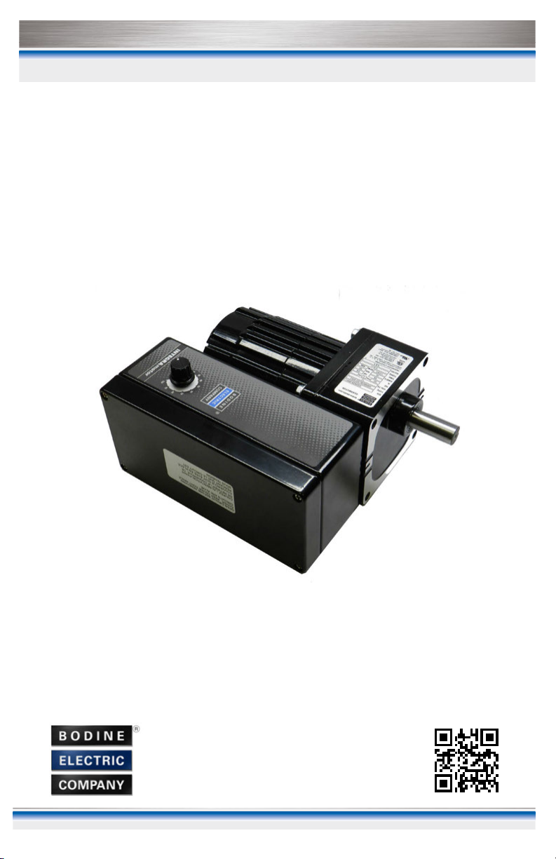
Instructions for Installation and Operation
Bodine 12 or 24VDC Type 34B/SR-WX
Variable Speed Brushless DC
™
INTEGRAmotor
This apparatus is suitable for use in Class I, Division 2,
Groups A, B, C, D, or unclassified locations.
Specifications
Speed (RPM) .....................................................0.6-658
Torque (lb-in.).......................................................9-205
Gear Ratio Range ...........................................3.8:1 to 312.4:1
Power (HP)........................................... 1/5 (12V) or 1/4 (24V)
Control Input
Max. Continuous Amps ...............................19.0 (12V) or 11.0 (24V)
www.bodine-electric.com
07401116.A

TABLE OF CONTENTS
This manual contains the basic information needed to install and operate
a Bodine INTEGRAmotor 34B4/SR-WX brushless DC gearmotor & control
system that is certified for use in Class I Division 2 hazardous locations.
This manual does not profess to cover all details or variations in equipment,
nor to provide for every possible contingency associated with installation,
operation, or maintenance. No warranty of fitness for purpose is expressed
or implied. It is the responsibility of the user to determine whether the
installation location is hazardous, and to what degree it is hazardous. Should
further information be desired or should particular problems arise which are
not covered sufficiently for the user’s purpose, the matter should be referred
to the Bodine Electric Company.
IMPORTANT SAFETY PRECAUTIONS ..................................3
QUICK REFERENCE ..................................................4
PRODUCT SPECIFICATIONS ..........................................5
INSTALLATION .....................................................6
Step 1 – Mount the 34B4/SR-WX Gearmotor ..........................6
Step 2 – Remove the Control Enclosure Cover ........................8
Step 3 – Attach Conduit to Control Enclosure .........................8
Step 4 – Make Electrical Connections ...............................8
Step 5 – Attach the Control Enclosure Cover.........................10
Step 6 – Operate the 34B4/SR-WX Gearmotor .......................10
Step 7 – Control Calibration (Optional) ..............................11
TROUBLESHOOTING ...............................................13
WARRANTY .......................................................15
FIGURES
Figure 1 – Quick Reference for Installation and Operation ...............4
Figure 2 – Mounting Dimensions .....................................7
Figure 3 – Installed Conduit Hub .....................................8
Figure 4 – Location of Control Components and Connections. ............9
Figure 5 – 34B4/SR-WX Gearmotor Shown with Cover Attached ........11
RoHS COMPLIANCE
This document certifies that the Bodine Electric type 34B4/SR-WX gearmotor
is manufactured with materials and processes that comply with European
Directive 2011/65/EU on the Restriction of Hazardous Substances (RoHS).
© Copyright 2015 Bodine Electric Company.
All rights reserved. All data subject to change without notice. Printed in U.S.A.
2
www.bodine-electric.com
IMPORTANT SAFETY PRECAUTIONS
The use of electric motors and gearmotors, like the use of all electronically
powered equipment, is potentially hazardous. The degree of hazard can
be greatly reduced by proper design, selection, installation, and use, but
hazards cannot be completely eliminated. The reduction of hazard is the joint
responsibility of the user, the manufacturer of the driven or driving equipment,
and the manufacturer of the motor or generator.
The Bodine type 34B motor was evaluated by Underwriters
Laboratories (UL) for compliance to UL standards 508C and
1004-1 and CSA standards C22.2 No. 14 and C22.2 No. 100. Motor
construction recognition is documented in UL file E47177. The gearmotor is also
a UL listed product, documented in UL file E474208 for hazardous locations. This
product was also evaluated by Underwriters Laboratories for compliance to
UL standard 1836, CSA standard C22.2 No. 213, and ISA standard 12.12.01. It is
suitable for use in Class I, Division 2, Groups A, B, C, D hazardous locations and
bears the mark shown above.
Please read through this operations manual in detail and observe those
paragraphs with the safety alert symbol.
!
WARNING
This indicates a potentially hazardous situation which,
if not avoided, could result in death or serious injury.
This indicates a potentially hazardous situation which,
CAUTION
if not avoided, may result in property damage.
!
WARNING/AVERTISSEMENT
Explosion hazard. Do not disconnect while the circuit is live or unless the
area is known to be free of ignitable concentrations.
Risque d’explosion – avant de deconnecter l’equipement, couper le courant
ou s’assurer que l’emplacement est designe non dangereux.
!
WARNING/AVERTISSEMENT
Explosion hazard. Substitution of components may impair suitability for
Class I, Division 2.
Risque d’explosion – La substitution de composants peut rendre cet
équipement inadapté à une utilisation en environnement de Classe I, Div. 2.
www.bodine-electric.com
3
QUICK REFERENCE
IMPORTANT
Read this manual completely and carefully before making any connections.
Pay special attention to all warnings, cautions, and safety rules. Failure to
follow the instructions could produce safety hazards which could injure
personnel or damage the control, gearmotor, or other equipment. If you
have any doubts about how to connect the control or gearmotor, refer to
the detailed sections of this manual.
This apparatus is suitable for use in Class I, Division 2, Groups A, B, C, D, or
unclassified (non-hazardous) locations.
1. Mount the gearmotor using the threaded holes in the face of the gearbox
and couple the load mechanism to the gearmotor drive shaft.
2. Remove the cover of control enclosure.
3. Attach conduit to control enclosure using a UL listed conduit fitting.
4. Run wire through the conduit and connect to control circuit board.
5. Reinstall cover on control enclosure.
6. Turn on power and adjust speed with the potentiometer on the control
enclosure.
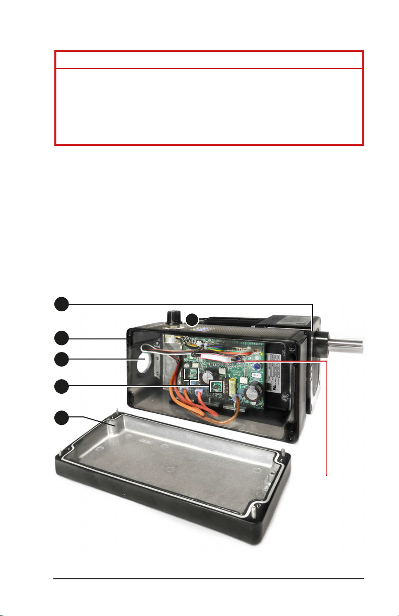
1
6
2
3
4
5
Control enclosure
cover (steps 2 and 5)
4
Direction Connector
(jumper)
Figure 1 – Quick Reference for Installation and Operation
www.bodine-electric.com
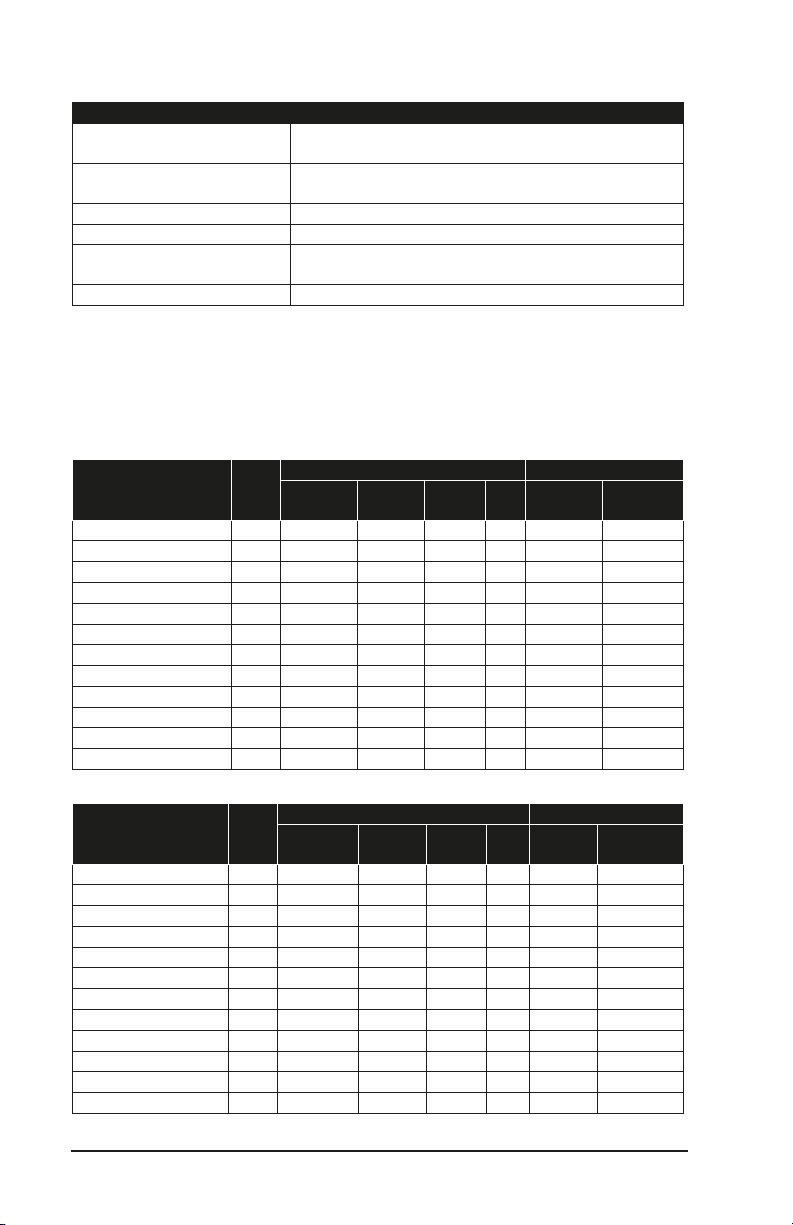
PRODUCT SPECIFICATIONS
Parameter
Specification
GEARMOTOR OUTPUT
CONTROL INPUT
Wt.
(lbs)
Speed
(rpm)
Torque
(lb-in)
Gear
Ratio
Volts
(VDC)
Max Cont.
Amps
GEARMOTOR OUTPUT
CONTROL INPUT
Wt.
(lbs)
Speed
(rpm)
Torque
(lb-in)
Gear
Ratio
HP
Volts
(VDC)
Max Cont.
Amps
Locations: Hazardous locations Class I, Division 2, Groups A, B, C, D or
Power Supply Voltage: 12-Volt models: 12 to 14 VDC
Ambient Temperature: -20º to 40º C (operating)
Speed Regulation: 2% at 2500 RPM
Speed Range
(at high speed shaft or rotor):
Acceleration Time: adjustable, 0.35 to 8.0 seconds
(non-hazardous) unclassified locations.
24-Volt models: 24 to 35 VDC
12.5:1 (200 to 2500 RPM) at rated load
and rated supply voltage
Tables 1 and 2 list the current models available, which are all parallel shaft
gearmotors. Other configurations of Bodine’s type 34B/SR gearmotor with
different gear reducers are possible. Contact Bodine for details on those.
TABLE 1 - 12 Volt Models
Type
34B4BEBL/SR-WX4 11.6 0.6 to 8 205 312.4:1 1/5 12 19.0
34B4BEBL/SR-WX4 11.6 1.2 to 15 200 172.1:1 1/5 12 19.0
34B4BEBL/SR-WX4 11.6 2.0 to 26 185 97.5:1 1/5 12 19.0
34B4BEBL/SR-WX3 11.6 3.0 to 38 190 65.5:1 1/5 12 19.0
34B4BEBL/SR-WX3 11.6 3.6 to 46 185 54.7:1 1/5 12 19.0
34B4BEBL/SR-WX3 11.6 4.5 to 57 157 43.9:1 1/5 12 19.0
34B4BEBL/SR-WX3 11.6 6.7 to 99 106 29.7:1 1/5 12 19.0
34B4BEBL/SR-WX2 11.6 9.8 to 123 77 20.4:1 1/5 12 19.0
34B4BEBL/SR-WX2 11.6 14 to 181 46 13.8:1 1/5 12 19.0
34B4BEBL/SR-WX2 11.6 21 to 266 31 9.4:1 1/5 12 19.0
34B4BEBL/SR-WX2 11.6 36 to 455 18 5.5:1 1/5 12 19.0
34B4BEBL/SR-WX2 11.6 52 to 658 9 3.8:1 1/5 12 19.0
TABLE 2 - 24 Volt Models
HP
34B4BEBL/SR-WX4 11.6 0.6 to 8 205 312.4:1 1/4 24 11.0
34B4BEBL/SR-WX4 11.6 1.2 to 15 200 172.1:1 1/4 24 11.0
34B4BEBL/SR-WX4 11.6 2.0 to 26 185 97.5:1 1/4 24 11.0
34B4BEBL/SR-WX3 11.6 3.0 to 38 190 65.5:1 1/4 24 11.0
34B4BEBL/SR-WX3 11.6 3.6 to 46 185 54.7:1 1/4 24 11.0
34B4BEBL/SR-WX3 11.6 4.5 to 57 157 43.9:1 1/4 24 11.0
34B4BEBL/SR-WX3 11.6 6.7 to 99 106 29.7:1 1/4 24 11.0
34B4BEBL/SR-WX2 11.6 9.8 to 123 77 20.4:1 1/4 24 11.0
34B4BEBL/SR-WX2 11.6 14 to 181 46 13.8:1 1/4 24 11.0
34B4BEBL/SR-WX2 11.6 21 to 266 31 9.4:1 1/4 24 11.0
34B4BEBL/SR-WX2 11.6 36 to 455 18 5.5:1 1/4 24 11.0
34B4BEBL/SR-WX2 11.6 52 to 658 9 3.8:1 1/4 24 11.0
www.bodine-electric.com
Type
5

INSTALLATION
This product should only be installed by a qualified person familiar with its
operation and associated hazards, and knowledgeable about the special
requirements for installation in hazardous locations. The National Electrical
Code (NEC), local electrical and safety codes, and when applicable, the
Occupational Safety and Health Act (OSHA) should be observed to reduce
hazards to personnel and property.
!
WARNING/AVERTISSEMENT
Explosion hazard. Do not disconnect while the circuit is live or unless the
area is known to be free of ignitable concentrations.
Risque d’explosion – avant de deconnecter l’equipement, couper le courant
ou s’assurer que l’emplacement est designe non dangereux.
!
WARNING/AVERTISSEMENT
Explosion hazard. Substitution of components may impair suitability for
Class I, Division 2.
Risque d’explosion – La substitution de composants peut rendre cet
équipement inadapté à une utilisation en environnement de Classe I,
Division 2.
Step 1: Mount the 34B4/SR-WX Gearmotor
CAUTION
The PCB of this 34B4/SR-WX gearmotor is vulnerable to static electrical
charges. This gearmotor is packaged in an anti-static bag and should
be removed from the bag only in an area protected from electrostatic
discharges (ESD).
This apparatus is suitable for use in Class I, Division 2, Groups A, B, C, D or
unclassified locations.
Install this 34B4/SR-WX gearmotor onto a secure mounting surface by
inserting screws into the four threaded holes in the face of the gearbox. See
Figure 2 for size and location of the mounting holes. An optional L-bracket kit,
Bodine model number 0970, is available for floor mounting.
If this 34B4/SR-WX gearmotor is operated or used outdoors, it must be
installed under a cover that protects it from direct exposure to rain or snow.
6
www.bodine-electric.com

(.8625) typ.
4.06±.02 Sq.
typ.
3.375±.010
(1.6875) typ.
[4] 1/4-28 UNF-2B
Depth .50 min.
Note: The following dimensions may differ
on custom 34B/SR-WX designs
a. Drive shaft dimensions and position
in relation to the control box
b. Speed potentiometer location
c. Conduit hole location and size
.6250
.6245
ø
4.02 Max.
7.983 max.
6.973 max.
typ.
3.375±.010
(3.548)
7.874 max.
(1.6875)
b
(1.93)
2.00±.03
(5.81)
typ.
(1.11)
.1875/.1855 sq. x
1.12 long key
.560±0.15
ø .802
max.
ø 1.31
not machined
a
(1.76)
c
[4] Terminal box cover screws
field installation tightening torque
18-26 lb-in.
Figure 2 – Standard 34B/SR-WX Mounting Dimensions
www.bodine-electric.com
(3.189)
14-18 lb-in.
field installation
tightening torque
[2] ground screws
(7.265)
3.937 Max.
ø 1.125/1.063
(hole for 3/4 NPT
conduit hub)
7

Step 2: Remove the Control Enclosure Cover
!
WARNING/AVERTISSEMENT
Open circuit before removing cover. Keep cover tight while circuits are alive.
Coupez l’alimentation avant de retirer le couvercle. Ce couvercle doit être
en place pendant que le circuit est sous tension.
The cover of the control enclosure is fastened with the four provided screws,
one at each corner. Either a Philips or a flat screwdriver can be used to loosen
the captive screws and remove the cover.
Figure 3 – Installed Conduit Hub.
Step 3: Attach Conduit to the Control Enclosure
Figure 2 shows the location of a 1.125” / 1.063” diameter hole in the side of the
control enclosure. The hole is for installation of a UL listed 3/4” NPT conduit
hub. The conduit hub shown in the Figure 3 is McMaster part number 7864T42
and is one example. Follow the manufacturer’s instructions for installing the
hub onto the control enclosure and then attach the conduit.
Step 4: Make Electrical Connections
CAUTION
The printed circuit board (PCB) of the 34B4/SR-WX gearmotor is vulnerable
to electrostatic discharges (ESD). Do not contact the PCB unless precautions
are followed to prevent ESD.
This 34B4/SR-WX gearmotor is factory-wired so that the drive is enabled as
soon as power is applied and speed is controlled using the potentiometer
in the side of the control enclosure. If remote control of the gearmotor is
desired, please contact our technical support staff at 773-478-3515 or via
info@bodine-electric.com.
Power and ground connections are made using three wires routed through
the conduit and into the 34B4/SR-WX gearmotor control enclosure. The
power wires must be terminated with ¼” quick disconnect receptacles.
8
www.bodine-electric.com

Connect the (+) side of the power supply to the tab labeled “+VM” on the
circuit board inside the control enclosure. Connect the (-) side of the power
supply to the tab labeled “PCOM”. Use one of the two copper ground screws
in the bottom of the control enclosure to attach the ground wire. See Figure
4 for location of the three connections.
Select Direction of Drive Shaft Rotation
Bodine 34B4/SR-WX gearmotors can be configured so that the drive shaft
rotates either clockwise or counterclockwise. The drive shafts of gearmotors
with an even number of gearing stages (indicated by an even number at
the end of the product type, as in 34B4BEBL/SR-WX2) are factory-set to
rotate counterclockwise. Drive shafts of gearmotors with an odd number
of gearing stages, such as 34B4BEBL/SR-WX3 will rotate clockwise. If the
application requires the drive shaft to rotate opposite the factory setting,
simply remove the plug-in direction connector inside the control enclosure.
See Figure 4 for location of the connector.
Fusing: The 34B4/SR-WX gearmotor must be protected by a user-supplied
fuse. In a system with multiple INTEGRAmotors, each one must be protected
separately. Make sure the fuse is connected in series with the (+) lead of the
power supply. The power supply must be fused with a JDYX2 fuse with a
maximum rating of 25 Amps. The fuse must be located outside the hazardous
location area or installed in a suitable enclosure.
Route all wires through conduit hub
(not shown).
Connect ground
wire with one of
the copper screws.
Connect wire from (-) side of
power supply to “PCOM”
www.bodine-electric.com
MX (Max Speed)
adjustment pot
Figure 4 – Location of Control Components and Connections
TQ (Torque/Current)
adjustment pot
Direction Connector
(jumper)
Connect wire from (+) side of
power supply to “+VM”
ACC (Acceleration)
adjustment pot
J4 Connector
9

Step 5: Attach the Control Enclosure Cover
!
WARNING/AVERTISSEMENT
Open circuit before removing or attaching the cover. Keep cover tight while
circuits are alive.
Coupez l’alimentation avant de retirer le couvercle. Ce couvercle doit être
en place pendant que le circuit est sous tension.
The cover of the control enclosure is fastened with the four provided M4
screws, one at each corner. Either a Phillips or a flat screwdriver can be used
to tighten the captive screws to 14-18 lb-in. and attach the cover.
Step 6: Operate the 34B4/SR-WX Gearmotor
!
WARNING
• Recheck all connections.
• Do not remove the cover over the electronics when the power is ON to
avoid personal injury caused by electrical shock.
• Do not attempt to install or remove the electrical connector when the power
supply is turned on. Do not attempt to wire circuitry while power is on.
CAUTION
• Check that gearmotor is securely mounted.
• Test 34B4/SR-WX gearmotor unloaded first.
• Check all rotating members. Be sure keys, pulleys, etc. are securely
fastened and safety guards are in place.
• Check for proper mounting and alignment of products, and verify safe
loading on shafts and gears.
1. Start the Gearmotor
a. Turn the DC power supply on.
b. The gearmotor should start running at the set speed if there is no remote
switch to enable the drive. The factory setting is zero speed, so a new
gearmotor should not turn at this point. But if the speed pot has already
been moved by a previous user, the gearmotor will run at the speed set by
that user.
2. Adjust Speed
a. Turn speed potentiometer.
3. Stop the Gearmotor
a. Turn the DC power supply off.
10
www.bodine-electric.com

Speed
Potentiometer
Figure 5 – 34B4/SR-WX gearmotor shown with cover attached to control
enclosure and showing the location of the speed potentiometer.
Step 7: Control Calibration (Optional)
!
WARNING
Do not remove the control box cover when the power is ON in a Class I,
Div. 2 hazardous location. Always adjust the control outside the hazardous
location area.
!
WARNING
Use a non-metallic or insulated adjustment tool for internal adjustments.
Circuit components are not at ground potential and accidental short
circuiting and shock hazard may occur with conducting tools. Adjustment
should be made only by qualified service personnel.
!
WARNING
Never rely on logic circuitry as a means of disabling the gearmotor or
control. To prevent unsuspected mechanical motion and potential injury,
the AC power should always be disconnected from the control power
supply whenever logic circuits or the driven equipment are serviced. When
a battery is used, the DC supply to the control should be disconnected.
The factory settings of the control are satisfactory for most applications.
However, there may be some cases where it is desirable to limit the maximum
speed of the gearmotor, or to limit its stall torque, or to change how quickly
it accelerates. These performance characteristics can be adjusted with
potentiometers on the control board inside the terminal box. Because the
control enclosure must be opened and the gearmotor must be running when
these adjustments are made, this must be done before the gearmotor is
installed in the hazardous location.
www.bodine-electric.com
11

See Figure 4 for the location of the following adjustment potentiometers.
Maximum Speed Potentiometer: The gearmotor is calibrated to run at the
speed listed on its nameplate when the external speed potentiometer is
set to “100”. Turn the Max Speed (MX) potentiometer on the control board
counterclockwise to reduce the maximum speed.
Torque (Current) Limit Potentiometer: The TQ potentiometer (Figure 4) has
been calibrated so that the peak current limit of the 12 volt model is factoryset to 30 Amps and the peak current limit of the 24 volt model is factory-set to
27 Amps. In some cases, it may be desirable to reduce the peak current limit
to a level less than the factory setting, in order to protect drive mechanisms,
such as gearing, from damage due to overloads. Turn the TQ trim potentiometer
counterclockwise to decrease the torque and clockwise to increase the torque.
Acceleration Adjustment Potentiometer: The ACC potentiometer (See Figure 4)
can be used to adjust the gearmotor’s acceleration time. A counterclockwise
adjustment decreases the acceleration time down to a minimum of
approximately 0.35 seconds from zero to full speed. A clockwise adjustment
increases the rate up to a maximum of approximately 8 seconds from zero to
full speed.
12
www.bodine-electric.com

TROUBLESHOOTING
!
WARNING
• Do not remove the cover over the electronics when the power is ON to
avoid personal injury caused by electrical shock.
• Do not attempt to install or remove the electrical connector when the power
supply is turned on. Do not attempt to wire circuitry while power is on.
If you encounter a problem, read all instructions and double-check the wiring.
Even if the 34B4/SR-WX gearmotor itself is defective, it may be that another
defective component in the system caused it to fail, in which case replacing
the gearmotor alone and not tending to the root cause of the failure may
result in another damaged product. Table 3 may assist in troubleshooting
foreseeable problems which may occur during installation and operation.
If problems persist, contact your source of purchase or a Bodine Authorized
Service Center and describe the problem in detail. Do not disassemble
the product unless authorized by Bodine Electric Company. Performing
unauthorized repairs will void the warranty and invalidate third-party
certifications.
General Evaluation – Knowing the circumstances under which the problem
occurred can help to identify the root cause of the problem. The following
are two questions you should ask yourself before disassembling the system:
Has the system ever operated properly? If the system was just installed and
hasn’t worked right from the beginning, then it is possible that something
wasn’t done correctly in the installation. Review all wiring or incorrect
programming of remote devices. If the system has been working for an
extended period of time and just recently stopped working, then this would
indicate that the system was initially installed properly but has somehow
changed. Focus instead on failed components or deteriorated wiring.
Is the problem continuous or intermittent? If the problem always occurs and
never goes away, then it would indicate something inherently wrong in the
connections or a defective component. On the other hand, if the system operates
properly most of the time and only occasionally does something wrong, then
this might indicate loose connections or electrical noise interference.
www.bodine-electric.com
13

TABLE 4 - General problem evaluation method
SYMPTOM
PROBABLE CAUSE
CORRECTIVE ACTION
Incorrect power
supply wiring
Incorrectly sized
power supply
Does not operate
Operates, but speed
can’t be adjusted
Operates, but won’t
come up to speed
Operates, but with abnormal
speed variations
Operates, but won’t stop
with zero speed signal
Operates, but won’t
maintain speed under load
Blown fuse Replace fuse.
No speed signal
Gearmotor is overloaded
Gearmotor is damaged
Defective speed
potentiometer
Gearmotor is overloaded
Incorrectly sized
power supply
Speed setting too low
Defective speed
potentiometer
Incorrectly sized
power supply
Gearmotor is overloaded
Check that power source
is switched on.
Check connections.
Look for shorts and
repair as required.
Replace power supply
with unit having sufficient
voltage and current
capacity to provide rated
voltage under full load
Check if speed
potentiometer is
working properly.
Check wiring for speed
potentiometer
Reduce load
Replace gearmotor
with stronger model
Contact Bodine or an
Authorized Service
Center for assistance.
Contact Bodine or an
Authorized Service
Center for assistance.
Reduce load
Replace gearmotor
with stronger model
Replace power supply
with unit having sufficient
voltage and current
capacity to provide rated
voltage under full load
Increase speed
Replace gearmotor
with model having
higher gear ratio
Contact Bodine or an
Authorized Service
Center for assistance.
Replace power supply
with unit having sufficient
voltage and current
capacity to provide rated
voltage under full load
Reduce load
Replace gearmotor
with stronger model
14
www.bodine-electric.com

BODINE LIMITED WARRANTY
The Bodine Electric Company warrants all products it manufactures to be free
of defects in workmanship and materials when used under Normal Operating
Conditions and when applied in accordance with nameplate specifications.
When Bodine motors and gearmotors have been purchased with and used
only with appropriately applied Bodine controls, this warranty shall be in
effect for a period of twenty-four months from date of purchase or thirty
months from date of manufacture, whichever comes first. Bodine motors and
gearmotors used with non-Bodine controls and Bodine controls used with
non-Bodine motors and gearmotors are covered by a standard twelve-month
warranty period.
The Bodine Electric Company will repair, replace, or refund at its option, any of
its products, which has been found to be defective and is within the warranty
period, provided that the product is shipped freight prepaid, with previous
authorization, to Bodine Electric, or to the nearest Bodine Authorized Service
Center. At its option, all return shipments are F.O.B. Bodine’s plant or Authorized
Service Center. Bodine is not responsible for removal, installation, or any other
incidental expenses incurred in shipping the products to or from Bodine.
This warranty is in lieu of any other expressed or implied warranty - including
(but not limited to) any implied warranties of merchantability and/or fitness for
a particular use or purpose.
Bodine’s liability under this warranty shall be solely limited to repair or
replacement of the Bodine product within the warranty period and Bodine
shall not be liable, under any circumstances, for any consequential, incidental
or indirect damages or expenses associated with the warranted products.
Commutator and/or brush wear and its associated effects are normal
occurrence and are not covered by this warranty unless otherwise agreed
to by Bodine in writing.
Proof of purchase of motor or gearmotor and matching control as a system
must be provided with any claim.
Product Type:_____________________ Serial No.____________________
Date of Purchase:____________ Place of Purchase:_______________
www.bodine-electric.com
15

Bodine offers over 1,200 standard
C
E
R
T
I
F
I
E
D
Q
U
A
L
I
T
Y
M
A
N
A
G
E
M
E
N
T
S
Y
S
T
E
M
gearmotors, motors and
system-matched speed controls.
Visit www.bodine-electric.com
for all your motion control needs.
Bodine offers the widest selection of variable-speed AC, permanent magnet DC and
brushless DC fractional horsepower gearmotors and motors in the industry. For
complete specifications, 3D CAD drawings, or to order online, visit bodine-electric.com.
A
N
M
A
G
Y
T
E
I
M
L
E
A
N
U
Q
D
E
I
F
I
T
R
E
C
T
S
Y
S
T
ISO
ISO
E
M
9001:2008
201 Northfield Road | Northfield IL 60093 U.S.A. | 773.478.3515
info@bodine-electric.com | www.bodine-electric.com
07401116.A
 Loading...