

Bodine Quality in Motion 890 Installation Instructions Manual

Control Serial Number
Installation Instructions for
Model No. 890 Electronic F-B-R Kit
Purchase Date
Installed By
The Model 890 F-B-R Kit may be
used with FPM chassis Models 810,
830, 850, and encased Models 815,
835, and 855.
CAUTION
This manual provides instructions
for installing the Model No. 890
Electronic F-B-R Kit with Bodine
FPM SCR Speed Controls. Please read the instruction manual
provided with your control first. It will direct you to this supplement
when necessary. Follow the instructions in their proper sequence.
The electronic Forward-Brake-Reverse (F-B-R) Board controls the
motor’s direction of rotation through an isolated low-voltage signal
from the Model 888 Analog Interface Board. The signal can also
come from a personal computer or a programmable controller,
provided that the signal is isolated. A low power 2-pole, 3-position
rotary switch can be used in place of the signal. When the direction
signal is changed, the motor will decelerate, approach 0 speed,
reverse direction, and then accelerate to the selected speed. This
protects the motor, gearing, and other drive components from
damage from high reversing torques.
© Copyright 2011 Bodine Electric Company
Data subject to change without notice.
FIGURE 1. Top view of electronic Forward-Brake-Reverse Board showing
components and connections to speed potentiometer and F-B-R Switch
Mounting Screws
and Nuts (2)
For Braking
Resistor
4-Pin Connector
Braking Resistor
Socket J7
Socket J8
FIGURE 2. Top view of FPM Control with Model 888 Analog Interface Board
WARNING
Always disconnect the 115 VAC line power to the control
before installing the F-B-R Kit.
1. Select Braking Resistor–A 100 Ohm 25 Watt resistor is connected
to the board for use with control Models 810 and 815. For control
Models 830 and 835, the 100 Ohm resistor should be replaced
with the 50 Ohm 25 Watt resistor. For control Models 850 and
855, the 100 Ohm resistor should be replaced with the 25 Ohm 25
Watt resistor included in the kit. Simply remove the two screws
and nuts holding the 100 Ohm resistor to the board (Figure 1) and
fasten the proper resistor in its place, using the same screws
and nuts.
For Model 888 Analog Interface Board only.
Remove the four white nylon mounting
screws which fasten down the analog
board (Figure 2), and move the board out of
the way to get to the driver board.
201 Northfield Road | Northfield Illinois, 60093, U.S.A. | Phone 773.478.3515 | www.bodine-electric.com | info@bodine-electric.com 07400134B
2. Remove the jumper assembly at J2 on the driver board (Figure 3).
For Models 810, 815, 830, 835, 850, and 855 only. Fasten the three
1.5-inch nylon “spacers” to the driver board with the nylon hex
nuts provided (Figure 4). Access holes for a 1/4-inch nut driver
are provided on the bottom of the mounting bracket. Hold a nylon
hex nut in place with a nut driver and thread a long spacer onto
the hex nut with your other hand (finger tight only).
FIGURE 3. Top view of FPM Control with Driver Board only
3. Insert the 4-pin connector from the F-B-R Board into connector
J2 on the driver board (Figures 1 and 3).
4. Insert the ribbon cable provided in your F-B-R Kit into J1 on the
driver board (Figure 3) and J8 on the F-B-R Board (Figure 1).
5A. For Models 810, 815, 830, 835, 850, and 855 only.
(1) Identify the wired connector for the speed pot and F-B-R
Switch or speed and direction input signals (Figure 1). Refer
to Manual No. 07400156 for instructions for making electrical
connections. After connections have been made, insert the
connector into J7 on the F-B-R Board.
(2) On chassis controls, place the F-B-R Board on the spacers
component-side-up (see Figure 4) or component-side-down
to save space. On encased controls, the F-B-R Board must
be mounted component-side-down. Next, secure the F-B-R
Board with three nylon hex nuts provided in the F-B-R Kit.
5B. For Model 888 Analog Interface Board only.
The instructions below describe how to assemble a 3-board
control as shown in Figure 5. Alternately, to provide better
access to TB2, the interface board may be mounted above the
F-B-R Board (use 1.625 inch spacers between the driver board
and F-B-R Board, and 1.5 inch spacers between the F-B-R and
interface boards).
Socket J1
Socket J2
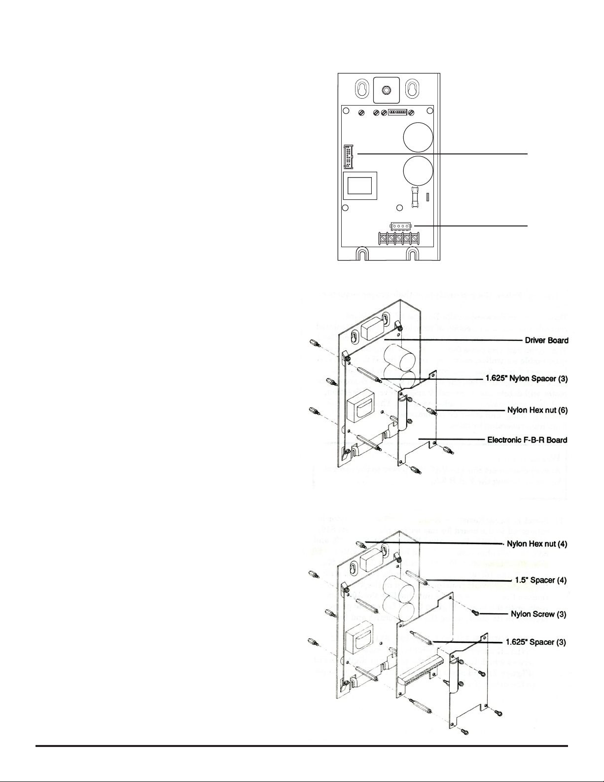
FIGURE 4. Assembling the electronic F-B-R Board to the Driver Board
(1) Position the analog board in its original location on the
spacers on the driver board.
FIGURE 5. Assembling the electronic F-B-R Board
(2) Fasten the analog board to the spacers using three 1.625 inch
to the Model 888 Analog Interface Board
threaded nylon spacers provided in the F-B-R Kit and one
nylon screw (Figure 5).
(3) Insert the ribbon cable from J3 of the analog board (Figure 2)
to J7 of the F-B-R Board (Figure 1).
(4) Place the F-B-R Board on the spacers component-side-
up (see Figure 5) or component-side-down to save space.
Then secure the F-B-R Board with the three nylon screws
provided in the F-B-R Kit.
Refer to the instruction manual provided with your control for
operating instructions.
201 Northfield Road | Northfield Illinois, 60093, U.S.A. | Phone 773.478.3515 | www.bodine-electric.com | info@bodine-electric.com 07400134B
 Loading...