

CATALOG S
up to 1,000 lb-in. | Parallel Shaft Gearmotors
Rated Current
(Amps)
Accy
Shaft
No Accy
Shaft
Accy
Shaft
No Accy
Shaft
24V Models With Class F Temperature Rating
90/130V Models With Class F Temperature Rating
Speed
(rpm)
Rated Torque
(lb-in.)
Radial Load
(lbs.)
Capacitor
(µF/VAC)
Model
Number
Permanent Split Capacitor, Non-synchronous (TEFC) CAPACITOR IS REQUIRED
Fixed Speed Rating
Variable Speed (SOA) Ratings
Motor
Fixed Speed Rating
Variable Speed (SOA) Ratings
230/460V
Speed
Torque
Motor
Speed
(rpm)
Torque
(lb-in.)
Torque
(lb-in.)
Torque
(lb-in.)
Three-Phase, Inverter duty, Non-synchronous (TEFC)
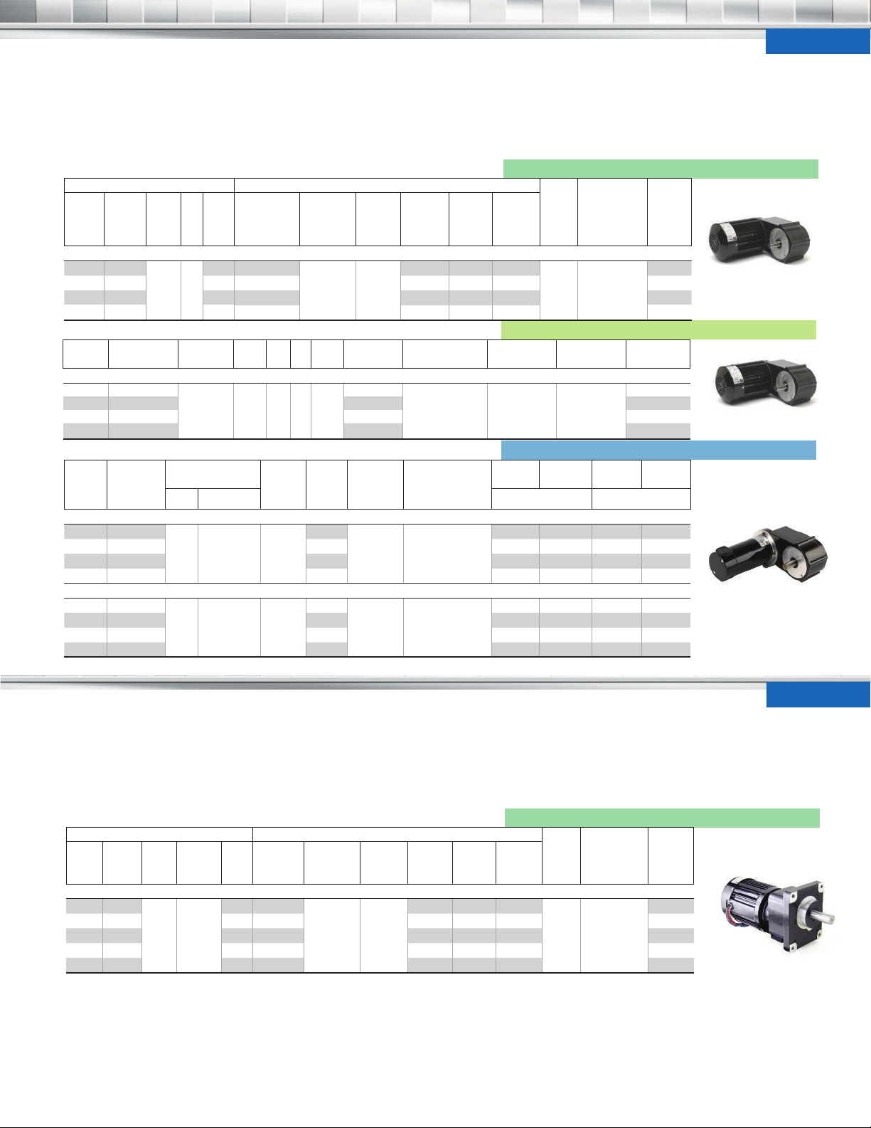
HG
• Unvented gearhousing
• Flexible mounting and high
torque in a compact package
Speed
Torque
(rpm)
(lb-in.)
Three -Phase, Inverter duty, Non-synchronous (TEFC)
16 1,000
30 600 56
38 480 45
63 289 27
16 599
30 310 56 5257
38 250 45 5258
63 150 27 5259
Speed
(rpm)
HP
3/8 1.9
Rated
Torque
(lb-in.)
Gear
A
Ratio
108
Motor HP V Hz Ph Amps Gear Ratio
1/5 115 60 1 2.7
24V 90/130V 24V 90/130V
• Face-mount from
drive shaft side
• Models with accessory
shafts are ideal for mounting
encoders or brakes
1
Speed
Range (rpm)
2-21
3-41 464 776 464
4-51 373 623 373
7-85 224 368 224
Frequency
Range (Hz)
10-90
Motor HPGear
Ratio
Torque
variable
108
Radial
Load (lbs.)
Type
Torque
@ 10 Hz
(lb-in.)
Torque
@ 60 Hz
(lb-in.)
896 1,000 896
350
Product Type
2
Variable Speed—Pacesetter Inverter Duty AC Gearmotors
Torque
@ 90 Hz
(lb-in.)
30.0/250
Radial
Load
(lbs.)
350 42R6BFPP-HG
Product
Type
Product Type
42R6BFCI-HG
Permanent Magnet DC Gearmotors
• See Page 36 for capacitors
and terminal boxes
• See page 40 for
reference dimensions
230V
Model
Number
2245
2247
2248
2249
Fixed Speed—AC Gearmotors
5255
Type 42R-HG Inverter Duty
Type 42R-HG
23 680
45 353 56 6845 6445
56 284 45 6856 6456
93 170 27 6893 6493
16 / 23 481 / 680
31 / 45 249 / 353 56
38 / 56 200 / 284 45
64 / 93 120 / 170 27
12 — 1/3
— 1.8 / 2.4 1/6 / 1/3
108
108
350 33A7BEPM-HG
350 33A7BEPM-HG
6823 6423
— —
— —
— —
— —
up to 1,000 lb-in. | Parallel Shaft Gearmotors
• Unvented gearhousing
for universal horizontal
mounting
• Selectively hardened
steel gears for quietness
and hardened steel spur
(rpm)
(lb-in.)
28 1000
34 850 50
47 650 36
57 540 30
85 360 20
(230/460V)
HP
Amps
3/4 2.7/1.3
gearing on subsequent
stages for high output
torque and long life
• Extra heavy-duty bearings
and seals
Gear
Range
Ratio
2.7-38
60
3.2-46 850 850 850
4.4-63 650 650 650
5.3-76 540 540 540
8.0-114 360 360 360
Frequency
Range (Hz)
10-90
Torque
Type
Constant
@ 10 Hz
1,000 1,000 1,000
• Face or base mounting
• Oversize drive shaft
• Models with accessory
shafts are ideal for mounting
encoders or brakes
1
@ 60 Hz
Variable Speed—Pacesetter Inverter Duty AC Gearmotors
@ 90 Hz
— —
— —
— —
— —
6323 6023
6345 6045
6356 6056
6393 6093
Radial
Load
Product Type
(lbs.)
250 48R6BFPP-CG
Type 33A-HG
CG
• See Page 36 for accessories
• See page 39 for
reference dimensions
Model
Number
9360
9350
9336
9330
9320
Type 48R-CG
Inverter Duty
11
(oz-in.)
Ratio
(µF/VAC)
Type
Number
Permanent Split Capacitor Normal Slip, Non-synchronous CAPACITOR IS INCLUDED
Permanent Split Capacitor High Slip, Non-synchronous CAPACITOR IS INCLUDED
Permanent Split Capacitor, Synchronous CAPACITOR IS INCLUDED
Rated Torque
Accy
Shaft
No Accy
Shaft
Accy
Shaft
No Accy
Shaft
24V
130V
24V Models With Class F Temperature Rating
130V Models with Class F Temperature Rating
CG
Parallel Shaft Gearmotors | up to 1,000 lb-in., continued
Permanent Magnet DC Gearmotors
Speed
(rpm)
(lb-in.)
Rated Current
(Amps)
Motor HP
Gear
Ratio
Radial
Load
(lbs.)
Product Type
2
38 660
46 550 50 4885 4485
64 400 36 4884 4484
77 330 30 4883 4483
115 220 20 4882 4482
Type 42A-CG
42 580
50 480 50
69 350 36
83 290 30
125 190 20
A/T
Parallel Shaft Gearmotors | up to 120 oz-in.
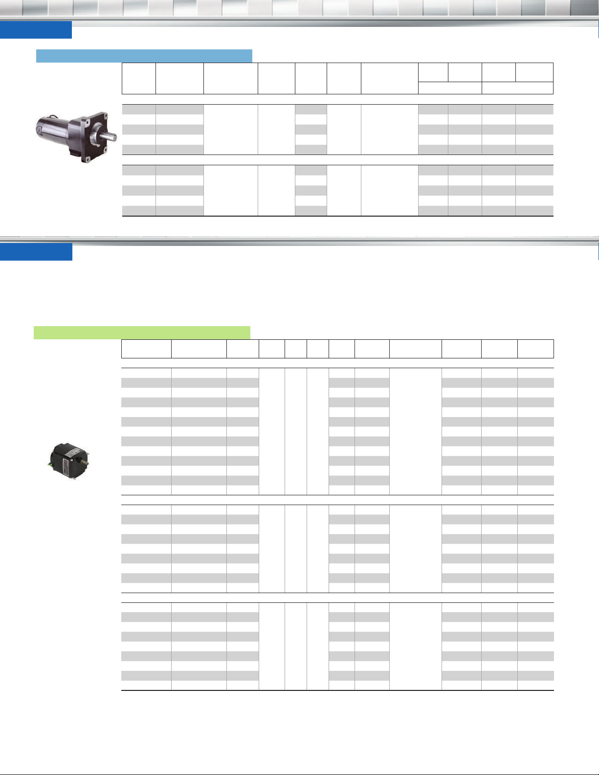
• Totally enclosed, nonventilated IP-20 rating
Fixed Speed—AC Gearmotors
Speed (rpm)
Type K-2A/T
60
4886 4486
— —
— —
18 7/16
250 42A7BEPM-CG
— —
— —
— —
60
3.3 7/16
• Permanently lubricated,
noise tested ball bearings
• Three-wire winding
simplifies reversing
Rated Torque
0.9 120 1/700
1.9 100 1/700 0.07 900 0.9/250 KCI-22T5 0726
5.6 95 1/700 0.07 300 0.9/250 KCI-22T4 0724
9 95 1/700 0.07 180 0.9/250 KCI-22T4 0723
13 95 1/450 0.083 120 1.0/250 KCI-23T4 0722
22 95 1/300 0.11 72 1.3/250 KCI-24T4 0733
26 80 1/300 0.11 60 1.3/250 KCI-24T3 0732
52 34 1/450 0.083 30 1.0/250 KCI-23A2 0719
52 59 1/300 0.11 30 1.3/250 KCI-24A2 0731
86 21 1/450 0.083 18 1.0/250 KCI-23A2 0718
86 35 1/300 0.11 18 1.3/250 KCI-24A2 0730
130 24 1/300 0.11 12 1.3/250 KCI-24A2 0729
260 12 1/300 0.11 6 1.3/250 KCI-24A2 0728
Motor HP V Hz Ph Amps
115 60 1
• Impedance protected to
prevent current overload
(gearmotor should not be
stalled when powered up)
250 42A7BEPM-CG
Gear
Radial Load (oz.)
0.07 1800
— —
— —
— —
— —
— —
• Capacitor is included
• See page 39 for
reference dimensions
Capacitor
0.9/250 KCI-22T5 0727
20
4786 4086
4785 4085
4784 4084
4783 4083
4782 4082
Product
Model
0.9 120 1/1000
2.3 95 1/1000 0.072 600 0.9/250 KCI-22T5 0744
4.9 95 1/1000 0.072 300 0.9/250 KCI-22T4 0743
10 88 1/800 0.083 120 1.0/250 KCI-23T4 0741
20 80 1/450 0.1 60 1.2/250 KCI-24T3 0750
40 44 1/450 0.1 30 1.2/250 KCI-24A2 0749
67 16 1/800 0.083 18 1.0/250 KCI-23A2 0737
67 27 1/450 0.1 18 1.2/250 KCI-24A2 0748
200 8.9 1/450 0.1 6 1.2/250 KCI-24A2 0747
1 120 1/2000
2 100 1/2000 0.069 900 0.9/250 KYC-22T5 0766
3 88 1/2000 0.069 600 0.9/250 KYC-22T5 0765
10 72 1/900 0.093 180 1.3/250 KYC-24T4 0776
15 20 1/2000 0.069 120 .09/250 KYC-22T4 0762
15 48 1/900 0.093 120 1.3/250 KYC-24T4 0775
25 29 1/900 0.093 72 1.3/250 KYC-24T4 0774
60 15 1/900 0.093 30 1.3/250 KYC-24A2 0772
100 8.9 1/900 0.093 18 1.3/250 KYC-24A2 0771
12
CATALOG S
115 60 1
115 60 1
0.072 1800
0.069 1800
0.9/250 KCI-22T5 0746
20
0.9/250 KYC-22T5 0767
20
Bodine Electric Company

XH Length
A
B
C
Lead/Cord Length (in.)
XH
A
B
Lead/Cord Length (in.)
HG
Parallel Shaft Gearmotor Dimensions
1.50±.03 3.42
KEY
0.750
Accessory
Shaft
(on Select
Models)
C
DC
Lead Exit
Motor
A
Diameter
AC Lead
Exit
Length
XH
Gearhead Type HG, page 11
Product Type
42R-HG
33A-HG
Only the first four characters of the product type are relevant to dimensions
42R6-HG 9.5 9.855 4.73 9.85 No 12
33A7-HG 10.5 10.547 3.39 9.80 Yes 24
Weight (lbs.)
[4] 1/4-20 UNC-2B
.50 deep min.
on 3.50 B.C.
Motor to
Gearhead
B
Height
(5.00)
Diameter
2.53 2.31
Height
45.0°
Acc’y Shaft
CG
Gearhead Type CG, page 11-12
Parallel Shaft Gearmotor Dimensions
Accessory Shaft
(on Select Models)
B
DC
Lead Exit
AC Lead
Exit
6-18 UNC-2B
[4] 5/1
X .50 MIN. DEEP
Product Type Weight (lbs.)
Motor
A
Diameter
XH
Length
.69
.880
2.398
3.000
1.000
(.905)
3.24±.03
Length
KEY
(1.09)
Key
3.70
(5.75)
2.375 2.375
[4] 7/16-14 UNC-2B
THRU
Diameter
2.375
(6.81)
3.436
Acc’y Shaft
48R-CG
42A-CG
Only the first four characters of the product type are relevant to dimensions
40
48R6-CG 34 12.849 5.917 No 12
42A7-CG 29 12.07 4.262 Yes 24
CATALOG S
Bodine Electric Company

CATALOG S
Weight
XH
B
to Base
C
Gearhead
D
E
F
G
Base
H
Base
I
I1
J
Length
J1
Width
K
Mounting
L
Cord/
(in.)
DC/BLDC
Product
(lbs.)
XH
(square)
A
(square)
B
Length
C
Diameter
D
Detail
E
Length
F
Width
G
Pattern Width
H
Mounting Hole
I
Mounting Hole
J
Detail
Lead/
Cord Length
(in.)
Lead Exit
A
Height
Wt.
J
Length
AC
Lead Exit
XH
Length
Gearhead Type 30R-D, K-2A/T, pages 5, 12
Type
Type K-2 Gearmotor
22 2.2 2.539
K-2T
24 2.7 3.023
K-2A
Type 30R-D Gearmotor
30R-D
23 2.3 2.507
24 2.6 2.866
30R1 5.8 5.242
30R4 7.5 6.000
Shaft
Length
B
Hub
Length
E
Shaft
D
Detail
Mounting Detail
Height
2.38 1.00 .250 Flat .255 .52 1.900 .356 .950
2.38 1.00 .250 Flat .255 .52 1.900 .356 .950
3.45 1.56 .500 Flat .554 1.125 2.652 .582 1.326
H
Shaft
Parallel Shaft Gearmotor Dimensions
G
(square)
I
Shaft
Diameter
C
Hub
Width
F
Shaft
Shaft
Hub
Hub
Mounting
Shaft Center to
Shaft Center to
D | K2-A/T
Mounting
[2]8-32
UNC-2A
[2]8-32
UNC-2A
[4]10-32
UNF-2B x .38
deep Max.
1223 2.4 2.664
12
1230R2 6.3 5.492
Right Angle Gearmotor Dimensions
Dimensions (in inches) are for reference only. For CAD drawings and specs, visit bodine-electric.com.
Accessory Shaft
(on Select Models)
L
AC/BLDC
Lead Exit
XH
A
Length
Motor
Diameter
F
DC Lead
Exit
Mounting
Detail
K
J
I
Gearhead Type 3N/3F, pages 13-14 (Mounts from Gearhead)
LengthADia-
(lbs.)
30R4-3N
34R4-3F
24A4-3F
22B4-3N
22B4-3N
INTEGRA
Only the first four characters of the product type are relevant to dimensions
7.5 7.192 3.34 4.30
9.3 8.61 4.02 4.37 No 12
5.3 7.422 2.42 3.57 Yes 24
5.4 7.677 2.378 3.80 No 12 or 24
5.4 8.79 2.93 3.82 No None
meter
Motor
Width
2.871 1.00 .500 Flat 1.28 1.28 2.56 2.111 2.00 1.188
Center of Shaft
To Base Edge
H
Shaft
Length
Shaft
Detail
Shaft
to Base
G
Shaft
Diameter
D
Shaft
Diameter
E
Shaft
Detail
Shaft
Length
Shaft
to
C
Center of
Shaft to
Gearhead
Width
J1
I1
Base
Length
B
Base
Width
Motor
to Base
Mounting
Hole
Mounting
Hole
3N | 3F
Acc’y
Detail
Shaft
No 12
[4]1/4 -20
UNF-2B x
.50 deep
Lead
Length
41
 Loading...