

Bodine GTD20A Installation Instructions Manual
GTD20A
Installation Instructions
BRANCH CIRCUIT
TRANSFER SWITCH/LIGHTING CONTROL DEVICE
UL 1008-BCELTS UL 924-Switch Bypass
WHEN USING ELECTRICAL EQUIPMENT, BASIC
! IMPORTANT SAFEGUARDS !
READ AND FOLLOW ALL SAFETY INSTRUCTIONS
1. This product is for use with generator-supplied (or central inverter system-supplied) lighting loads. Make sure all
connections are in accordance with the National Electrical Code and any local regulations.
2. To reduce the risk of electric shock, disconnect all power sources before servicing.
3. This product is for field installation.
4. This product is for use in indoor or damp locations where the ambient temperature is -20ºC minimum, +55ºC
maximum.
5. This product is UL Listed as either a Branch Circuit Emergency Lighting Transfer Switch (BCELTS) under UL 1008
or a Switch Bypass under UL 924. Use the proper wiring diagram in the appropriate section of these instructions.
6. An unswitched, normal AC power source (120 through 277 VAC, 50/60 Hz) and a direct, separate connection to a
generator-supplied or central inverter system-supplied emergency panel are required.
7. The use of accessory equipment not recommended by the manufacturer may cause an unsafe condition.
8. Do not use this product for other than intended use.
9. Servicing should be performed by qualified service personnel.
SAFETY PRECAUTIONS SHOULD ALWAYS BE
FOLLOWED, INCLUDING THE FOLLOWING:
SAVE THESE INSTRUCTIONS
CAUTION: THIS UNIT HAS MORE THAN ONE POWER SUPPLY CONNECTION POINT. TO REDUCE
THE RISK OF ELECTRIC SHOCK, DISCONNECT ALL POWER SOURCES BEFORE
INSTALLING OR SERVICING THIS UNIT.
SERVICE BY QUALIFIED PERSONNEL ONLY
NOTE: BEFORE INSTALLING THE CONTROL DEVICE, MAKE SURE THAT THE NECESSARY BRANCH
CIRCUIT WIRING IS AVAILABLE. AN UNSWITCHED SOURCE OF NORMAL POWER IS REQUIRED. A SEPARATE
CONNECTION TO A GENERATOR-SUPPLIED (OR CENTRAL INVERTER SYSTEM-SUPPLIED) CIRCUIT MUST ALSO
BE PROVIDED.
236 Mt. Pleasant Rd. • Collierville, TN 38017-2752 • Tech Support 888-263-4638 • Fax 901-853-5009 • www.philips.com/bodine
06/19/18
© Philips Emergency Lighting
70100047
INSTALLATION
CAUTION: THIS UNIT HAS MORE THAN ONE POWER SUPPLY CONNECTION POINT. TO REDUCE
THE RISK OF ELECTRIC SHOCK, DISCONNECT ALL POWER SOURCES BEFORE
INSTALLING OR SERVICING THIS UNIT.
NOTE: BEFORE INSTALLING THE CONTROL DEVICE, MAKE SURE THAT THE NECESSARY BRANCH CIRCUIT
WIRING IS AVAILABLE. AN UNSWITCHED SOURCE OF NORMAL POWER IS REQUIRED. A SEPARATE CONNECTION TO
A GENERATOR-SUPPLIED (OR CENTRAL INVERTER SYSTEM-SUPPLIED) CIRCUIT MUST ALSO BE PROVIDED.
STEP #1
MOUNTING THE GTD20A
> FAMILIARIZE YOURSELF WITH THESE INSTRUCTIONS BEFORE BEGINNING INSTALLATION.
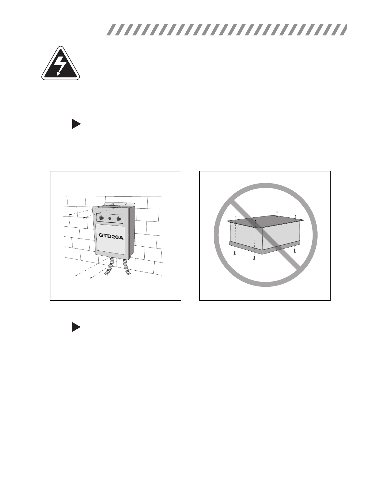
> Mount GTD20A in a convenient location using appropriate hardware (not supplied). See Illustration 1 for
typical installation. DO NOT MOUNT WITH LID FACING DOWN (See Illustration 2).
ILLUSTRATION 1
WALL MOUNTING
FACE DOWN MOUNTING (NOT APPROVED)
ILLUSTRATION 2
STEP #2
INSTALLING THE GTD20A
> Disconnect AC power from all supply circuits.
> Remove GTD20A lid and install necessary conduit and wiring (not supplied) to the GTD20A.
> Refer to the illustrations on the following pages for proper wiring connections and choose the correct
illustration for your application.
> Note: When using Class 2 power limited circuits, (for example, 0-10 VDC dimming connections)
remember to keep this wiring separate from high voltage wiring by using separate conduit and the
enclosure knockout provided.
> Replace GTD20A lid and secure.
2
 Loading...