

B463
Ni - Cd
Installation Instructions
FLUORESCENT EMERGENCY BALLAST
WHEN USING ELECTRICAL EQUIPMENT, BASIC
! IMPORTANT SAFEGUARDS !
READ AND FOLLOW ALL SAFETY INSTRUCTIONS
SAFETY PRECAUTIONS SHOULD ALWAYS BE
FOLLOWED, INCLUDING THE FOLLOWING:
1. To prevent high voltage from being present on red & yellow output
leads prior to installation, inverter connector must be open. Do not
join inverter connector until installation is complete and AC power
is supplied to the emergency ballast.
2. This product is for use with one (2-pin) double twin-tube (quad) or
one triple twin-tube compact uorescent lamp shown in the Lamp
Rating Chart.
3. Make sure all connections are in accordance with the National
Electrical Code and any local regulations.
4. To reduce the risk of electric shock, disconnect both normal and emergency
power supplies and inverter connector of the emergency ballast before servicing.
5. This emergency ballast is for factory or eld installation.
6. This product is suitable for damp locations where the ambient temperature is 0°C minimum, +50°C
maximum. Product is not suitable for heated air and wet outlets or hazardous locations.
7. An unswitched AC power source is required (120 or 277 VAC, 60 Hz).
8. Do not install near gas or electric heaters.
9. Do not attempt to service the battery. A sealed, no-maintenance battery is used that is not eld
replaceable. Contact the manufacturer for information on service.
10. The use of accessory equipment not recommended by the manufacturer may cause an unsafe
condition.
11. Do not use this product for other than intended use.
12. Servicing should be performed by qualied service personnel.
LAMP RATING CHART
Operates One 2-Pin Lamp
Lamp Type Wattage Base
Quad 10, 13, 18, 26 G24d
Triple 13, 18, 26 GX24d
SAVE THESE INSTRUCTIONS
THIS PRODUCT CONTAINS A RECHARGEABLE NICKEL-CADMIUM BATTERY.
THE BATTERY MUST BE RECYCLED OR DISPOSED OF PROPERLY.
A Division of Philips Electronics North America Corporation
236 Mt. Pleasant Rd. • Collierville, TN USA 38017-2752 • Tech Support 888-263-4638 • Fax 901-854-1630 • www.philips.com/bodine
02/06/09
© Philips Emergency Lighting
70046304
INSTALLATION
WARNING: TO PREVENT HIGH VOLTAGE FROM BEING PRESENT ON RED & YELLOW OUTPUT
LEADS PRIOR TO INSTALLATION, INVERTER CONNECTOR MUST BE OPEN. DO NOT JOIN
INVERTER CONNECTOR UNTIL INSTALLATION IS COMPLETE AND AC POWER IS SUPPLIED TO
THE EMERGENCY BALLAST.
NOTE: Make sure that the necessary branch circuit wiring is available. An unswitched
source of power is required. The emergency ballast must be fed from the same
branch circuit as the AC ballast.
STEP #1
INSTALLING THE EMERGENCY BALLAST
> Disconnect AC power from the xture.
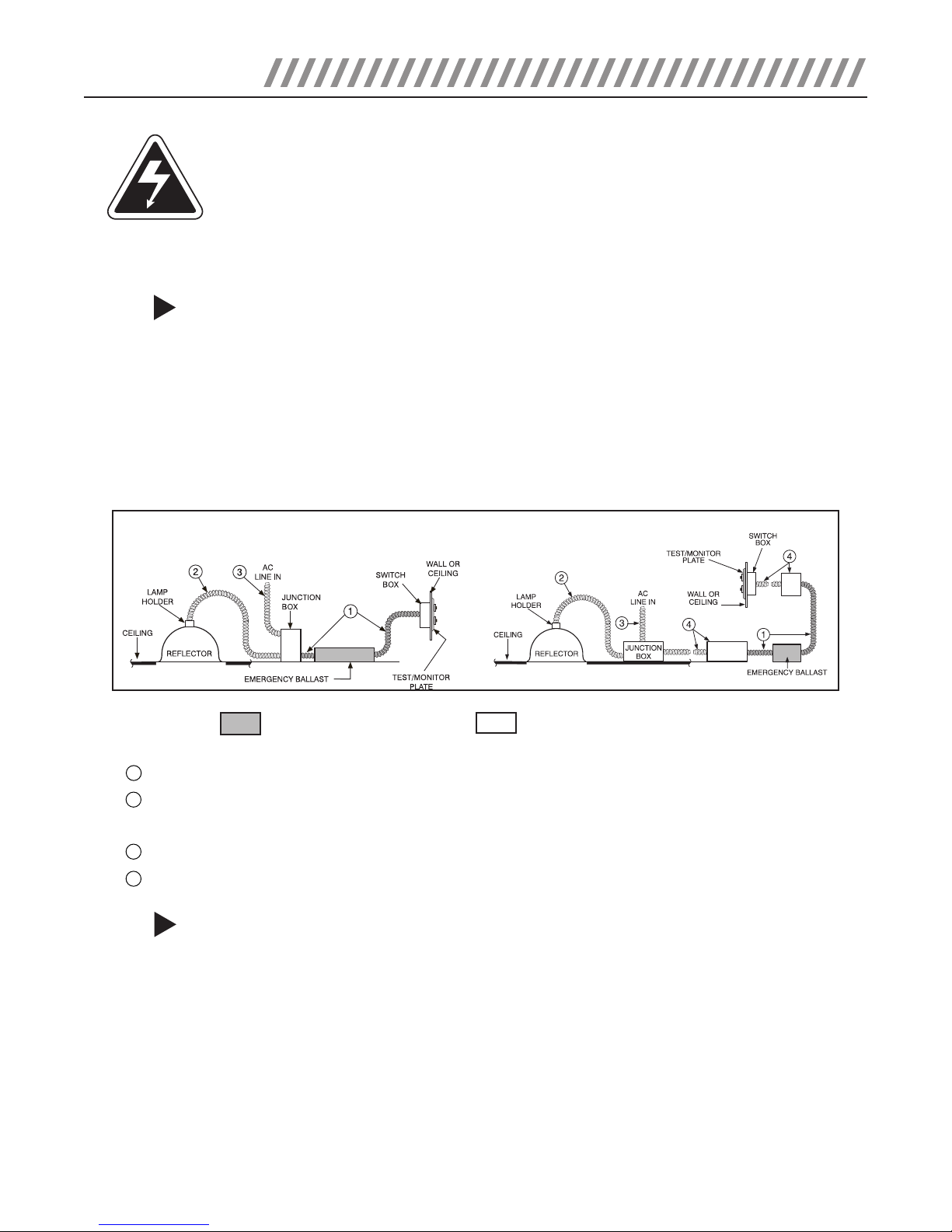
> Refer to illustration below to install the emergency ballast and test/monitor plate. Make electrical connec-
tions in accordance with the National Electrical Code and any local regulations. The test/monitor plate may
be installed close to the xture in the ceiling or at a remote location (up to 50 feet). The emergency ballast may be remotely installed up to 1/2 the distance the AC ballast manufacturer recommends remoting
the AC ballast from the lamp, or up to 50 feet, whichever is less. If no AC ballast is used, the emergency
ballast can be remotely mounted up to 50 feet away. Note: A switch box is not supplied.
STANDARD INSTALLATION
Emergency ballast
No Shading – Equipment supplied by others
REMOTE INSTALLATION
1 – Flexible conduit (supplied) to connect ballast wires.
2 – Existing conduit to run existing wires to lamp holder (AC ballast on junction box). If AC ballast is on
reflector, run yellow and blue wires from emergency ballast through this conduit.
3 – AC line in.
4 – Conduit and junction box (not supplied), necessary for remote installation.
STEP #2
WIRING THE EMERGENCY BALLAST
> See back page for detailed wiring schematics. The emergency ballast can be used with one- or two- lamp
xtures, and operates one lamp in the emergency mode.
> Cut xture wire between the lamp holder and AC ballasts and connect the blue emergency ballast wire to
the AC ballast and the yellow wire to the lamp holder.
> On switched xtures, an additional unswitched hot (120 or 277 VAC) wire must be run to the junction box
and connected to the emergency ballast.
> Connect LED by matching violet and brown leads. For optional tabbed LED, connect violet lead to positive
(+) tab (marked). For Illuminated Test Switch (ITS) connect as shown on wiring diagrams by matching
violet and brown leads and connecting the black leads to the emergency ballast white and white/black
wires.
> After installation is complete, supply AC power to the emergency ballast and join the inverter connector.
2
 Loading...