

Instructions for Installation and Operation
Filtered SCR Brushless DC
Motor Speed Controls (NEMA-12)
Model 3912, 0-2,500 rpm
Model 3913, 0-10,000 rpm
SPECIFICATIONS
Product Type.......................................... ABL-3912E/ABL-3913E
Input Voltage: ......................................... 115 VAC ± 10%, 50/60 Hz (Single Phase)
Input Current: ......................................... 12 Amps rms
Output Voltage: .......................................0 to 130 VDC
Continuous Output Current.............................. 3.0 Amps
Peak Output Current ...................................6.0 Amps
Ambient Temperature: .................................0° to 40° C (Maximum)
Control Hp Range: .....................................Up to 3/8 Hp
Control Speed Range: .................................. Up to 30:1
www.bodine-electric.com
07400212.C

IMPORTANT
Read this manual completely and carefully. Pay special attention to all
warnings, cautions, and safety rules. Failure to follow the instructions
could produce safety hazards which could injure personnel or damage
the control, motor, or other equipment. If you have any doubts about
how to connect the control or motor, refer to the detailed sections of
this manual.
QUICK REFERENCE
HAVE YOU?
❑ Read the installation and operation instructions contained
in this manual.
❑ Read and understood all of the precautions outlined in this
manual pertaining to potential hazards to personal safety
and equipment.
❑ Mounted the control properly. Details on Page 9.
❑ Connected the circular connector on the control output
cable to the corresponding circular connector on the
Bodine Brushless DC motor. Details on Page 9.
❑ Selected the proper control horsepower settings for the
motor being used. Details on Page 9.
❑ Installed the motor fuse. Details on Page 11.
❑ Provided an adequate grounded source of AC power.
Details on Page 11.
❑ Refer to the Operation Section of this manual for
preliminary start-up details and specific control functions.
Page 12.
2
www.bodine-electric.com

TABLE OF CONTENTS
QUICK REFERENCE CHECK LIST ..............................................2
GENERAL INFORMATION ...................................................4
CONTROL DESCRIPTION AND FEATURES ......................................4
SPECIFICATIONS ...........................................................5
IMPORTANT SAFETY PRECAUTIONS ..........................................6
INSTALLATION INSTRUCTIONS ..............................................9
Mounting the Control. . . . . . . . . . . . . . . . . . . . . . . . . . . . . . . . . . . . . . . . . . . . . . . . . . . . .9
Electrical Connections ...................................................9
Motor Cable Connection ..................................................9
Horsepower (DIP Switch) Settings .........................................9
Line Fuse Installation. . . . . . . . . . . . . . . . . . . . . . . . . . . . . . . . . . . . . . . . . . . . . . . . . . . .11
Motor Fuse Installation ..................................................11
Control Input Connections ...............................................11
AC Power Connections ..................................................11
OPERATING INSTRUCTIONS ................................................12
Preliminary Checks .....................................................12
Operating the Control ...................................................12
Internal Adjustments ....................................................13
Minimum and Maximum Speed ........................................13
Torque (Current) Limiting Adjustment ...................................14
Acceleration Adjustment .............................................14
Deceleration Adjustment .............................................14
TROUBLESHOOTING .......................................................15
SPECIALIZED WIRING APPLICATIONS .......................................17
Motor Cable ...........................................................18
Connecting Control Inputs From Remote Locations .........................19
Remotely Located Speed Control .........................................19
Remotely Located Braking (Disable), Direction of Rotation and
Deceleration Controls ...................................................20
Electronic Control Input Connections .....................................20
Electronic Speed Control ................................................21
Logic Signal Control of Braking, Direction of Rotation, and Deceleration .......21
Signal Isolation Using a Bodine Model 3984 Interface Module ................21
WARRANTY ...............................................................23
FIGURES
Figure 1 – Detail of Control Circuit Board in Enclosure ..........................10
Figure 2 – DIP Switch 7 and 8 Speed Range Settings ...........................10
Figure 3 – Horsepower (DIP Switch) Settings and Fuse Selection Chart ..........10
Figure 4 – Speed/Torque Curve Showing Reduced Torque at Lower Speeds .......14
Figure 5 – Interface Connector Detail ........................................19
Figure 6 – Remote Speed Control Connections ................................19
Figure 7 – Manual Switch and Relay Control Inputs ............................20
Figure 8 – Manual Speed Potentiometer/Interface Details ......................21
© 2017 Bodine Electric Company.
All rights Reserved. All data subject to change without notice. Printed in U.S.A.
www.bodine-electric.com
3

GENERAL INFORMATION
Thank you for selecting a Bodine Type ABL Encased Brushless DC Motor
Control. Your new control will provide the same excellent performance and
reliability that have been a Bodine tradition since 1905. Bodine Electric
Company takes pride in the quality of its products and in satisfying its
customers. Every effort has been made to provide you with a product free
of defects in design, workmanship, and materials. In order for us to maintain
our tradition of quality, please report any cases of unsatisfactory service or
products to Bodine Electric Company promptly.
About This Manual
This manual contains the basic information needed to install and operate
a Bodine Type ABL-3912E and ABL-3913E Brushless DC Motor Control. It is
organized in a systematic, step-by-step fashion so that the system may be set
up safely in the shortest possible time. It does not profess to cover all details
or variations in equipment, nor to provide for every possible contingency
associated with installation, operation, or maintenance. No warranty of fitness
for purpose is expressed or implied. Should further information be desired or
should particular problems arise which are not covered sufficiently for the
user’s purpose, the matter should be referred to the Bodine Electric Company.
The issuance of this manual does not confer to the recipient any license
to manufacture under any patents owned or controlled by the Bodine
Electric Company.
Safety Standards
Bodine products are designed and manufactured to comply to applicable
safety standards and in particular to those issued by ANSI (American
National Standards Institute), NEMA (National Electrical Manufacturers
Association), U.L. (Underwriters Laboratories, Inc.), and CSA (Canadian
Standards Association).
Bodine equipment “recognized by U.L., Inc.” are either labeled
with the UR or cURus marks. In addition, products that are CSA
certified are identified by the CSA mark. If you need specific
information regarding the third-party approval status of Bodine
products, contact the nearest Bodine representative, or the
home office.
CONTROL DESCRIPTION AND FEATURES
The ABL-3912E, and ABL-3913E Brushless DC Motor Controls are encased
style controls. They are supplied in their own enclosure to simplify mounting.
The controls operate from a nominal 115 VAC, 50/60 Hz. power source. They
provide electronic commutation and phase current switching needed to
4
www.bodine-electric.com

operate brushless DC motors. DIP switch selectable current limit settings
allow the ABL-3912E and ABL-3913E to be used with a wide range of fractional
horsepower motors and gearmotors.
The ABL-3912E and ABL-3913E provide a 130-Volt filtered output for improved
form factor, plus a built-in dynamic braking module. Motor speed is controlled
by a speed potentiometer mounted on the enclosure front panel. Direction
of rotation and braking are controlled from a “Forward-Brake-Reverse”
(F-B-R) switch also located on the front panel. Trim potentiometers on the
control circuit board allow additional fine tuning of minimum and maximum
speed settings, torque, acceleration and deceleration times. A built-in “Smart
Reverse™” circuit prevents plug reversing by dynamically braking the motor
to a stop before changing its direction. A built-in shutdown circuit disables
the control during over-voltage, under-voltage, or invalid commutation sensor
state conditions. Specific Bodine motor sizes which can be used with these
controls are listed in the Chart in Figure 3.
Accessory Items
• Model 3982 Extension Cable – extends cable between motor and control by six feet.
Both ends equipped with circular connectors for simplified connection. Length: 6 ft.
• Model 0895 Enclosure Sealing Kit – seals the ABL-3912E enclosure to provide
IP-44 level splash proof protection.
• Model 3984 Isolation Module – isolates the control from system controller
inputs, which may be at different potentials. This module is not required unless
the ABL-3912E is connected to a separate control system. See the “Specialized
Application Wiring” section of this manual.
Parameter Specification
Product Type ABL-3912E/ABL-3913E
Input Voltage: 115 VAC ± 10%, 50/60 Hz (Single Phase)
Input Current: 12 Amps rms
Output Voltage: 0 to 130 VDC
Continuous Output Current 3.0 Amps
Peak Output Current 6.0 Amps
Ambient Temperature: 0° to 40° C (Maximum)
Control Hp Range: Up to 3/8 Hp
Control Speed Range: Up to 30:1
Control Speed Regulation: Less than 1% of rated (Typical)
Line Voltage Compensation: Negligible speed change with changes
in line voltage
Acceleration Time Range: (Model 3912): 0.2 to 10 seconds
(0 to full speed)
(Model 3913): 0.5 to 30 seconds
(0-full speed)
Dimensions: inches: ( 6.2 W x 4.0 D x 8.5 H);
cm: (15.8 W x 10.2 D x 21.6 H)
Net Weight: 7.5 lbs. (3.4 kg.)
www.bodine-electric.com
5

IMPORTANT SAFETY PRECAUTIONS
The following safety precautions must be observed during all phases of
installation, operation, service, and repair of this motor control product.
Failure to comply with these precautions or with specific warnings elsewhere
in this manual violates safety standards of design, manufacture and intended
use of the products. Bodine Electric Company assumes no liability for the
customer’s failure to comply with safety requirements and practices.
The use of electric motors and generators, like that of all utilization of
concentrated power, is potentially hazardous. The degree of hazard can
be greatly reduced by proper design, selection, installation, and use but all
hazards cannot be completely eliminated. The reduction of hazards is a joint
responsibility between the user, the manufacturer of the driven or driving
equipment and the manufacturer of the control or motor.
The user should refer to Publication No. ANSI C5.1/NEMA MG 2. Safety
Standard for Construction and Guide for Selection, Installation and Use of
Electric Motors and Generators available from:
National Electrical Manufacturers Association
www.nema.org
Warnings (such as the example below) highlight procedures which present
potential danger to people. Cautions highlight possible danger to equipment.
Both are used throughout this manual and must always be followed.
WARNING
Dangerous voltages may be present in the electronic control and motor.
These voltages could cause serious injury or death. Use extreme caution
during handling, testing, and adjusting. Properly guard the electronic
control and motor to prevent accidental contact by all persons.
The chance of explosions, fires, or electric shocks can be reduced
with thermal and over-current protection, proper grounding, enclosure
selection, and good maintenance. The following safety considerations
are not intended to be all-inclusive. Specific references throughout this
manual should also be consulted.
CAUTION
These controls are designed to provide optimum performance when
used with Bodine Electric Company motors. They should not be used with
other manufacturer’s motors without first contacting the Bodine Electric
Company. Failure to contact Bodine in advance could cause damage to
the control or the motor.
6
www.bodine-electric.com

Inspecting the Control
Check the items you received against your purchase order. Carefully examine
the control (and any optional kits or parts) for shipping damage. Parts errors
should be reported to Bodine. Shipping damage claims should be made to the
freight carrier.
Before installation, review the application to confirm that the proper motor
and control have been selected. This should be done after reading this
manual and all applicable safety standards. If in doubt, contact your Bodine
representative, or the home office if there is no representative in your area.
Although Bodine Electric Company assists its customers in selecting motors
and controls for specific applications, determination of fitness for purpose or
use is solely the customer’s responsibility.
Normal Operating Conditions
Unless otherwise agreed to by Bodine, all control nameplate ratings are
based on the following normal operating conditions. Consult Bodine Electric
Company if variations beyond these limits are anticipated.
1. Continuous Duty: without frequent reversals or starts and stops.
2. Maximum Ambient Temperature: 50° C (122° F) for chassis controls; 40° C
(104° F) for all encased controls.
3. Voltage: Within 10% of nameplate rating.
4. Frequency: Within 5% of nameplate rating.
5. Combined Variation of Voltage and Frequency: Within a total of 10%
providing frequency variation does not exceed 5%.
Grounding
Both electronic controls and motors must be securely mounted and adequately
grounded. Failure to ground properly may cause serious injury to personnel.
Fusing
Both the control input and output are fused. When fuses are replaced, they
must always conform to the values and ratings specified on the control’s
nameplate or in the fuse chart in Figure 4.
Live Circuitry
Open-type electronics should be properly guarded or enclosed to prevent
accidental human contact with live circuitry. No work should be performed on
or close to the control or motor while the control is connected to the AC line.
If an AC line switch is used, it should be a Double Pole Single Throw (DPST),
so that both sides of the AC line are disconnected
Note: Motor over temperature sensing is not provided by this control.
www.bodine-electric.com
7

Environment
Open controls or controls in ventilated enclosures may emit flame during
failure. Bodine’s totally enclosed products are not explosion-proof, and Bodine
does not offer an explosion-proof motor, gearmotor, or control for hazardous
locations (e.g., in an environment of flammable or explosive gas, vapor, or
dust). Bodine recommends use of only approved explosion-proof products
in hazardous locations. The National Electric Code (NEC) allows exceptions,
but NEC and NEMA safety standards should be studied thoroughly before
exercising this option.
Moisture increases the electrical shock hazard of electrical insulation.
Therefore, open-type or unsealed controls not specifically designed for such
use, should be protected from contact with liquids or moisture.
Ventilated Products
Open, ventilated products are suitable for clean, dry locations where cooling air is
not restricted. Do not insert anything into a product’s ventilation openings.
Servicing
Emergency field repairs must be made only by authorized Bodine service
representatives. Repairs made by persons not authorized by the Bodine
Electric Company will void the warranty. Field repairs must be limited to
replacing an entire printed circuit board assembly. Because of the danger
of introducing safety hazards, do not install substitute parts or perform any
unauthorized modifications to electronic PC boards, components or motors.
To ensure continued compliance with the design specifications and safety
standards, the electronic control or motor should be returned to Bodine
Electric Company or an Authorized Service Center for servicing.
WARNING
To avoid injury because of unsuspected mechanical motion, always
disconnect the 115 VAC power to the control before performing any
service procedures on the motor, control, or driven equipment.
This manual does not purport to cover all details or variations in equipment,
nor to provide for every possible contingency to be met in connection with
installation, operation, or maintenance — no warranty of fitness for purpose
is expressed or implied. Should further information be desired or should
particular problems arise which are not covered sufficiently for the user’s
purpose, the matter should be referred to the Bodine Electric Company.
The issuance of this manual does not confer to the recipient any license to
manufacture under any patents owned or controlled by the Bodine Electric
Company.
8
www.bodine-electric.com

INSTALLATION INSTRUCTIONS
WARNING
This control should only be installed by a qualified technician, electrician,
or electrical maintenance person familiar with its operation and associated
hazards. The National Electrical Code (NEC), local electrical and safety
codes, and when applicable, the Occupational Safety and Health Act
(OSHA) should be observed to reduce hazards to personnel and property.
Circuitry is not at ground potential. Do not perform work on or near the
control while it is connected to the AC line.
CAUTION
Exposed circuit boards should be protected from electrostatic discharge.
The control board uses CMOS circuitry. Static discharge into the control
board must be avoided to prevent component damage.
Mounting the Control
Detailed mounting dimensions and CAD drawings are available online. The
control should be mounted vertically so that the control panel is readable
and the cabling extends from the bottom of the enclosure. This arrangement
provides optimum air flow around the control.
Electrical Connections
Read the following instructions as well as all of the applicable safety
recommendations, before making any electrical connections between the
control, motor, or other motion control electronics.
Motor Cable Connection
All electrical connections for motor phase outputs and commutation sensor
control inputs are prewired and terminated in a circular connector and cable
assembly attached to the control enclosure. To connect the ABL-3912E or
ABL-3913E controls simply mate the circular connector from the control to
the circular connector on the associated Bodine motor.
Horsepower (DIP Switch) Settings
Figure 1 shows the Horsepower Select switch on the main control board. It
contains eight switch levers numbered 1 through 8. The chart in Figure 3 shows
the proper DIP switch settings for various Bodine motor types. Determine the
first four digits of the motor’s type number from the nameplate. Find the same
four digits in the chart in Figure 3 to determine the proper settings of the DIP
switches. An insulated tool should be used to adjust the switch settings.
www.bodine-electric.com
9

(4.64)
Figure 1 - Detail of Control Circuit Board in Enclosure.
3.88 Max.
1.48 Min.
8.45 Max.
External Speed Pot Connections
MAX speed adjust
(CW increase)
MIN speed adjust
(CW increase)
Acceleration time
(CW increase)
Deceleration time
(CW increase)
Torque adjust
(CW increase)
RED FAULT
LIGHT
(Indicates a
problem with the
commutation
sensor
connections)
(4.55 Typ.)
Line Fuse
AC Line
Horsepower Settings
Motor Fuse
Commutation
Sensor Inputs
Control Inputs
Shown with optional
mounting brackets in the
vertical position.
AC Neutral
Motor
Phase
Outputs
Motor Fuse
A
B
C
Figure 1 - Detail of Control Circuit Board in Enclosure.
Typical MAX Motor Speeds with 10 K Speed Pot
DIP Switch
7
DIP Switch 8
CCW MAX
Pot
Calibrated
MAX Pot
CW MAX
1
Pot
T-Out Pulse
Width (µS)
ON ON 4400 6600 8800 275
ON OFF 6600 10,000 13,000 190
Factory
Setting
OFF ON 6600 10,000 13,000 190
OFF OFF 13,000 20,000 26,000 90
1. Max. Speed obtainable is dependent on motor winding (voltage, speed rating, resistance),
line voltage and load conditions.
Figure 2 – DIP Switch 7 and 8 Speed Range Settings
(.57 Typ.)
(.57 Typ.)
(9.20) Typ.
Control Motor or Rated DIP Switch Line Motor AC rms
Model Gearmotor Speed Levers in the Fuse Fuse Input
Number Type Hp (RPM) “On” Position (F1) (F2) Current
22B2… 1/16 2, 6, 8 MDA 6/10 2.7
ABL-3912E 22B4… 1/8 2500 1, 3, 6, 8 ABC 15 MDA 1-1/4 4.8
ABL-3913E
22B3… 1/11 1, 2, 6, 8 MDA 8/10 3.6
34B3… 1/5 1, 2, 3, 6, 8 MDA 1-1/2 6.7
34B4… 1/4 2, 4, 6, 8 MDA 2 8.0
34B6… 3/8 1, 5, 6, 8 MDA 2-1/2 11.1
22B4… 1/5
34B4… 1/3 1, 3, 4, 6, 8 MDA 2-1/2 9.5
10,000
1, 2, 3, 6, 8
ABC 15
MDA 1-1/2 6.7
Figure 3 - Horsepower (DIP Switch) Settings and Fuse Selection Chart
10
www.bodine-electric.com

Motor Commutation Phasing (60° standard)
All standard (stock) brushless DC motors and gearmotors manufactured by
Bodine Electric Company are designed for 60° commutation. The factory
setting for our BLDC speed controls is also for 60° commutation. It is possible
to configure our BLDC stock controls to operate non-Bodine BLDC motors
and gearmotors with 120° commutation angle. To change the sensor phasing
output on our stock controls for 120° commutated gearmotors or motors, set
DIP switch number 6 to the “Off” position. Please note that further application
details must be considered to properly match a non-Bodine BLDC motor with
one of our stock BLDC controls. To avoid damage or system performance
issues, please consult our Technical Support staff at 773-478-3515 or via
E-mail: info@bodine-electric.com.
Line Fuse Installation
The control input is protected by factory-installed fuse (F1) shown in Figure 1.
It should always be replaced with a fuse of the same type and rating as
indicated in the chart in Figure 3.
Motor Fuse Installation
The control output contains a motor fuse (F2) shown in Figure 1. The rating of
F2 will vary with the size of the motor used. To determine the proper rating,
locate the first four digits of your motor’s type number on the motor nameplate.
Find the same four digits in the chart in Figure 3 and use only the fuse which is
recommended. The ABL-3912E and ABL 3913E are supplied with a motor fuse
kit containing all of the fuses listed in Figure 3.
Control Input Connections
The controls on the front panel of the ABL-3912E and ABL-3913E are used to
adjust motor speed, braking and direction of rotation. The controls are prewired at the factory. Refer to the Operating Instructions for additional details.
AC Power Connections
AC power is supplied to the control through a pre-wired power cord. The
power cord should be the last connection made during installation and
always be disconnected first before servicing.
WARNING
The ABL-3912E and ABL-3913E must be plugged into a grounded AC outlet
using the power cord supplied. The outlet should be capable of providing
a continuous current of 12 amps. Do not defeat the safety feature of the
three-pronged plug. If your outlet is not a grounding-type AC outlet, have a
licensed electrician replace it with one that is.
www.bodine-electric.com
11

OPERATING INSTRUCTIONS
WARNING
Explosions, fires, or electric shock hazards can be reduced through
thermal and over-current protection, good maintenance, proper
grounding, and enclosure selection. Review safety considerations
outlined in “Safety Precautions” and “Installing the Control.”
Preliminary Checks
1. Before starting the control, check all fuses, connections, and adjustments
such as horsepower DIP switch settings.
2. Proper consideration should be given to all rotating members. Before
starting, be sure keys, pulleys, etc. are securely fastened. Proper guards
should be provided to prevent hazards to personnel while the equipment
is rotating.
3. Mechanical considerations such as proper mounting and alignment of
products, and safe loads on shafts and gears should be reviewed. Do not
depend upon gear friction to hold loads.
4. The motor or gearmotor should be securely mounted (because of possible
reaction torque). Test the motor/gearmotor unloaded to be certain that
proper connections have been made.
Operating the Control
WARNING
The 115 VAC line cord should be disconnected before starting
1. Toggle the input power switch to OFF and set the speed potentiometer to
ZERO (fully counterclockwise).
2. Set the F-B-R switch to the “Brake” position.
3. Connect the 115 VAC power cord to the external power source. Then toggle
the 115 VAC input power switch to the ON position.
4. Set F-B-R switch to forward or reverse depending on the direction of shaft
rotation you require.
5. Turn speed potentiometer knob until motor rotates. Then adjust the
potentiometer to achieve the desired speed. If you wish to reduce the
torque level, refer to Internal Adjustments below.
6. If the motor does not operate, check first if the POWER lamp on the outside
of enclosure and the red FAULT light on the inside are on. Then disconnect
the AC power cord and check all connections and fuses. If a fuse is blown
and the motor is not locked (stalled) or overloaded, do not replace the fuse.
The control may be damaged. Refer to Troubleshooting on page 15 and
follow instructions. If the motor is overloaded, reduce the load and replace
blown fuses with new ones of the proper type and rating. (See Figure 3.)
12
www.bodine-electric.com

Internal Adjustments
Your control has been factory-adjusted for the following settings:
Minimum speed: 0 RPM
Maximum speed: ABL-3912E: 2500 RPM; ABL-3913E: 10,000 RPM
Acceleration: ABL-3912E: 2 seconds; ABL-3913E: 5 seconds
Deceleration: ABL-3912E: 2 seconds; ABL-3913E: 5 seconds
Torque: 200% of rated (based on DIP switch settings)
Refer to Figure 1 for the trim potentiometer locations and approximate initial
settings. If you need to readjust the control for your specific applications,
proceed as follows:
WARNING
Use a non-metallic or insulated adjustment tool (such as a television
alignment tool) for internal adjustments. Circuit components are not at
ground potential and accidental short circuiting and shock hazard may
occur with conducting tools. Adjustment should be made only by
qualified service personnel.
Minimum and Maximum Speed:
The MIN and MAX trim potentiometers have been factory calibrated. The
lowest MIN trim potentiometer setting (fully counterclockwise) corresponds
to 0 RPM and the highest MIN setting (fully clockwise) corresponds to
approximately 30% of rated speed.
The lowest MAX trim potentiometer setting (fully counterclockwise)
corresponds to 60% of rated speed and the highest MAX trim potentiometer
setting (fully clockwise) corresponds to approximately 120% of rated speed.
Refer to Figure 1 for trim potentiometer location and settings. Adjustment of
the MIN and MAX trim potentiometers may have to be repeated several times
to arrive at the desired speeds.
NOTE: Increasing the MIN potentiometer setting will increase the maximum speed beyond
nameplate speed. The MAX trim potentiometer will need to be readjusted.
www.bodine-electric.com
13

Torque (Current) Limiting Adjustment
The TORQ trim potentiometer (Figure 1) has been calibrated so that the motor
will never see more than 200% to 250% of its rated current input. The motor’s
torque output can be reduced to zero or stall torque. Set the torque based
on the system load requirements. Torque may be reduced on lightly loaded
systems to protect drive mechanisms, such as gearing, from damage due to
overloads. Turn the TORQ trim potentiometer counterclockwise to decrease
the torque and clockwise to increase the torque.
RPM
2500
1725
250
172
0
0 100
Figure 4 - Speed/Torque Curve Showing Reduced Torque at Lower Speeds
50
100%
80 oz-in.
oz-in.
150
Filtered stall (140 oz-in.)
Acceleration Adjustment
Adjusting the ACCEL trim potentiometer (See Figure 1) counterclockwise
decreases the motor’s acceleration time down to a minimum of approximately
0.2 seconds (ABL-3912E) or 0.5 seconds (ABL-3913E). A clockwise adjustment
increases the rate up to a maximum of approximately 10 seconds (ABL-3912E)
or 30 seconds (ABL-3913E).
Deceleration Adjustment
Adjusting the DECEL trim potentiometer (See Figure 1) counterclockwise
decreases the motor’s deceleration time down to a minimum of approximately
0.2 seconds (ABL-3912E) or 0.5 seconds (3913E). A clockwise adjustment
increases the rate up to a maximum of approximately 10 seconds (3912E) or
30 seconds (3913E).
14
www.bodine-electric.com

TROUBLESHOOTING
WARNING
Disconnect the 115 VAC power cord from the power source before
working on the control, motor, or driven equipment.
All Bodine controls undergo extensive testing and calibration procedures to
detect and eliminate defects. Your control should not require maintenance under
normal conditions. If you encounter a problem, read all applicable instruction
literature provided with this control and accessories, and double check the
wiring. The charts on the following pages provide assistance in troubleshooting
common problems which occur during normal installation and operation.
If the problem persists, contact your source of purchase and describe
the problem in detail. Include all the nameplate data. Do not disassemble
the product unless authorized by Bodine Electric Company. Performing
unauthorized repairs or removing screws will void the Warranty.
ABNORMALITY CHECK POINT COUNTERMEASURE
CONTROL
BLOWS LINE
FUSE
MOTOR WILL
NOT START
Control or motor connected
to or shorted to earth ground
Shorted phase leads,
wiring incorrect
Damaged control Components
Open line fuse or motor fuse
Open power switch Set power switch to ON
Motor overloaded
TORQ trim pot is out
of adjustment
Speed potentiometer
set to zero
F-B-R switch in
BRAKE position
Damaged motor Repair or replace motor.
Check for shorts and
repair as required.
Correct wiring.
Contact Bodine for
assistance.
Replace fuse. Refer to
Figure 3 for proper value.
Correct load or choose
larger motor.
Visually check setting
(Figure 1). Adjust TORQ
trim pot, page 14.
Increase speed
potentiometer setting
Set switch to FORWARD
or REVERSE.
www.bodine-electric.com
15

ABNORMALITY CHECK POINT COUNTERMEASURE
MAX trim pot set too low Adjust trim pot, page 13.
MOTOR WILL
NOT COME UP
TO SPEED
MOTOR SPEED
IS ADJUSTABLE
OR PULSATES
MOTOR WILL
NOT MAINTAIN
SPEED UNDER
LOAD
Speed potentiometer
set to low
Motor overloaded
TORQ trim pot is out
of adjustment
Wrong horsepower setting
Damaged component
on the control board
Increase speed
potentiometer setting.
Re-examine the load
parameters
Visually check setting (Figure 1)
Adjust TORQ trim pot, page 14.
Check DIP switch
setting, page 10.
Contact Bodine for assistance.
Wrong horsepower setting Check DIP switch setting, page 10.
Motor and load not
correctly aligned
Perform alignment.
Damaged motor Repair or replace motor.
Speed potentiometer
set too low
Wrong horsepower setting
TORQ trim pot is out
of adjustment
Motor overloaded
Increase speed
potentiometer setting.
Check DIP switch
setting, page 10.
Visually check setting (Figure 1).
Adjust TORQ trim pot, page 13.
Re-examine the load
parameters.
MOTOR WILL
NOT STOP WITH
SPEED POT
ADJUSTED
NO SPEED
ADJUSTMENT
16
MIN trim potentiometer
is set too high
Open connection on
speed potentiometer
Defective speed
potentiometer
Defective speed
potentiometer
Open connection on
speed potentiometer
Turn the MIN trim pot
CCW until motor stops.
Check potentiometer
connections.
Replace the potentiometer.
Contact Bodine for assistance.
Replace the potentiometer.
Contact Bodine for assistance.
Check potentiometer
connections.
www.bodine-electric.com

SPECIALIZED WIRING APPLICATIONS
The Bodine ABL-3912E and ABL-3913E encased controls provides optimum
performance and easy installation when used with Bodine Brushless DC
motors and gearmotors. The control can be used with brushless DC motors
from other manufacturers provided electrical specifications and performance
requirements are compatible. The user bears the responsibility for determining
if another motor is fit for use with the ABL control. If you have doubts, Bodine
will assist you in determining if another motor is fit for use with this control.
The ABL-3912E and ABL-3913E are designed for applications where the
motor and control act as a stand-alone system. If the motor and control are
to be part of a larger motion control system requiring electronic control or
operation from a remote control panel, the model ABL-3910C or ABL-3921C or
ABL-3911C Chassis Type Controls are recommended.
If however, the ABL-3912E, and ABL-3913E must be adapted to fit a unique
situation, the following information should be reviewed carefully and
understood before proceeding with any wiring changes.
WARNING
The 115 VAC power line to the control should be the very last connection
made. Disconnect the power line before making any other electrical
connections.
CAUTION
The control board signal common is not at ground potential, any external
signal or equipment connected to the control must be electrically isolated
from ground (e.g., relay or optically isolated). Nonisolated signals will
damage the control and/or associated external equipment.
CAUTION
Read the following instructions as well as all of the applicable safety
recommendations, before making any electrical connections between the
control, motor, or motion control electronics.
www.bodine-electric.com
17

Motor Cable
Motor Cable
The ABL-3912E, and ABL-3913E Encased Controls are equipped with a pre-
wired cable which mates with the cable on associated Bodine Brushless DC
Motors. If the cables supplied with the motor and control are not long enough,
they can be extended using the Bodine Model 3282 Extension Cable. No more
than one 3282 extension should be used. This assures that the 12 ft. maximum
recommended distance between the control and the motor will be maintained.
The pin designations for the circular connector are as follows:
The ABL-3912E, and ABL-3913E Encased Controls are equipped with a
prewired cable which mates with the cable on associated Bodine Brushless
DC Motors. If the cables supplied with the motor and control are not long
enough, they can be extended using the Bodine Model 3982 Extension Cable.
No more than one 3982 extension should be used. This assures that the 12 ft.
maximum recommended distance between the control and the motor will
be maintained.
The pin designations for the circular connector are as follows:
Pin No. Lead Color Wire Gage Circuit Designation
1 Brown 18 Motor Phase A
2 Red 18 Motor Phase B
3 Orange 18 Motor Phase C
4 Grn/Yel Tracer 24 Chassis ground
10 Black 24 Circuit Common
12 Brown 24 Hall Sensor A
9 Red 24 +12 VDC
13 White 24 Hall Sensor B
14 Green 24 Hall Sensor C
11 Shield 24 Drain*
* The drain is terminated at the control board. Do not terminate the
The shield common is at a dangerous potential above ground and presents
a voltage hazard. Contact with the shield could cause serious injury or
death. If a non-Bodine cable is used or if a special cable is fabricated,
care should be taken to insulate all exposed shield to avoid serious injury.
The shield should only be connected to COM terminal on the Commutation
Sensor Input Connector at the control. No other shield connection should
be made.
drain at the motor.
WARNING
CAUTION
Only copper wire with a minimum 60° C rated insulation is recommended
if Bodine cable assemblies are not used.
18
www.bodine-electric.com
Connecting Control Inputs From Remote Locations
11
U23
R83
RP1
J1
1
J3
1
R82
R84
R81
J2
HB
EN1
HC
HA
EN2
INTERFACE
120
FSEL
BRAKE OUT
DIR
CONTROL INPUTS
DECLCOM
DECEL
DISCOM
DISABLE
DIRCOM
H+
H-
COM
COMMUTATION
Control Inputs
INTERFACE CONNECTOR -
Disconnect whenever external
inputs are used.
DO NOT REMOVE
"BRAKE OUT"
Connector
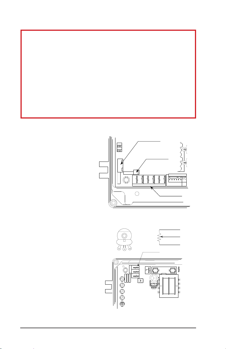
Figure 4 - Interface Connector Detail
CAUTION
The INTERFACE connector on the main control circuit board must be
disconnected if the ABL front panel controls are overridden by remotely
located controls or by a system controller. See Figure 5.
NOTE
The red plastic plug at the bottom of the ABL enclosure may be removed
to accommodate remote signal cables. It should be replaced with a IP-44
grade cord grip. If IP-44 splash protection is not required, any cord grip or
strain relief designed to fit a 3/8-18 NPT tapped hole may be used.
INTERFACE CONNECTOR -
Remotely Located Speed Control:
To connect a remote speed
potentiometer, proceed as follows:
1. Solder the three leads of
appropriate length to a 10K
ohm potentiometer as shown
in Figure 6.
2. Attach 1/4” female quick
disconnect terminals to
the other ends of the three
potentiometer leads.
3. Mount the potentiometer in the
desired location.
4. Connect the speed pot leads
to the ABL control board as
follows:
• Blue to Terminal “S1”
• Orange to Terminal “S2”
• Yellow to Terminal “S3”
FSEL
120
INTERFACE
Figure 5 - Interface Connector Detail
Front View
S1
60618 USA
CHICAGO IL
R93R92 R95
R94R91
TORQMINMAX DECELACCEL
LED2
Figure 6 - Remote Speed Control Connections
Disconnect whenever external
inputs are used.
J3
J2
BRAKE OUT
1
DECLCOM
DECEL
DO NOT REMOVE
"BRAKE OUT"
Connector
DISCOM
CONTROL INPUTS
Ohms
S3
S2
SPEED POT
C 1992
S1
S2
COMPANY
ELECTRIC
S3
BODINE
CAL
R90
DIRCOM
DISABLE
DIR
Control Inputs
10K
Speed Pot Terminals
LINE FUSE
F1
D3
D2
C3
COMMUTATION
Yellow
Orange
Blue
R82
R81
R84
R83
U23
11
RP1
1
COM
EN2
EN1
HC
HB
HA
H+
H-
J1
S3
S2
S1
PILOT
www.bodine-electric.com
19
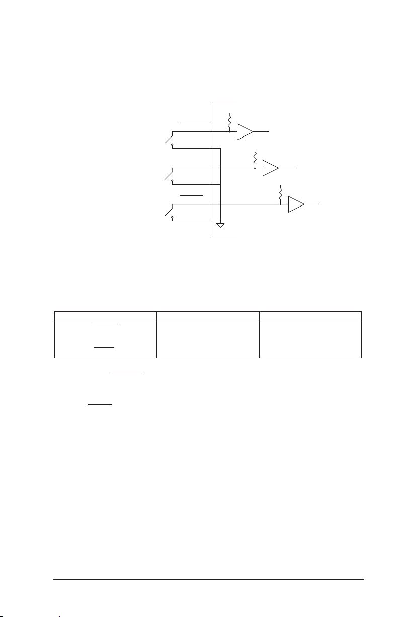
Remotely Located Braking (Disable), Direction
4000 Series CMOS
of Rotation, andDeceleration Controls
Mechanical switches or relays can be used to switch the control inputs
shown in Figure 5. Figure 7 shows a schematic representation of manual or
relay switched inputs.
NOTE: The
DISCOM,
DIRCOM,
DECLCOM,
S1, and COM
terminals on the
control board are
all connected in
common.
DISABLE
DISCOM
Manual
Switches
or Relay
Contacts
Figure 7 - Manual Switch and Relay Control Inputs.
DIR
DIRCOM
DECEL
DECLCOM
12V
10K
Signal
Common
4000 Series CMOS
12V
10K
4000 Series CMOS
12V
10K
The following chart lists the control functions relative to the state of the
mechanical switches or relays.
Switch Closed Open
1
DISABLE
2
DIR
3
DECEL
1. When the DISABLE switch is closed the motor will be dynamically braked.
2. A “Smart Reverse Circuit” prevents plug reversing when the DIR switch is
opened or closed. The motor will brake to a stop before changing direction.
3. The DECEL switch controls soft stops and starts. The degree of acceleration and
deceleration can be varied with the trim potentiometers on the control board.
See Page 14.
4. The output shafts of gearmotors with odd number of stages (Bodine type
designations ending with W3, E1, or E3) will rotate in the opposite direction.
Stop Run
4
CW
Decelerate Accelerate
CCW
4
Electronic Control Input Connections
Optional Interface Boards are available from Bodine and other manufacturers.
They provide electrical isolation between the input signal and the brushless
DC motor control circuitry, and are recommended for motion control
applications requiring electronic control of motor speed, rotational direction,
deceleration, and braking.
20
www.bodine-electric.com
Electronic Speed Control
Motor speed can be controlled with a 0 to +10 VDC isolated signal with 0.1 mA
current capability in lieu of the manual speed potentiometer. This speed
control input should be connected to terminal S2 on the control board. The
common side of the signal must also be isolated and connected to terminal
S1 on the main control board.
Logic Signal Control of Braking, Direction of Rotation, and Deceleration
Motor braking (or disable), direction of rotation and deceleration can be
controlled using optically isolated logic signals from a programmable
controller, personal computer, or other electronics.
WARNING
Never rely on logic circuitry as a means of disabling the motor or control.
To prevent unsuspected mechanical motion and potential injury, the 115
VAC power should always be disconnected whenever logic circuits or
the driven equipment are serviced.
Exercise extreme caution when using Programmable Logic Controllers (PLCs).
Although some may claim to have optically isolated output modules, their output
commons may be connected to other circuitry either within or connected to the
PLC. In such cases, the PLC outputs should be isolated from the ABL control, by
a relay or by an electronic isolation module, to prevent damage to the PLC or the
ABL control.
If a Programmable Controller with a
relay output module is not available,
AC or DC outputs from the PLC can
be used to drive separate relay coils.
See PLC user’s manual for application
information. See Figure 6 to determine
how to connect relay contacts to the
ABL-3912E and ABL-3913E.
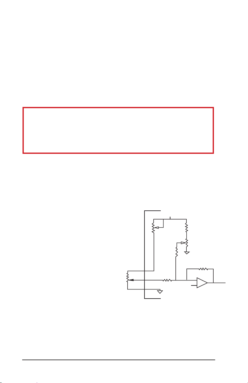
Signal Isolation Using a Bodine
Model 3984 Interface Module:
Follow the installation instructions
provided with the module to isolate
the input signals between the
control electronics and the ABL
Control. See Figure 7 for control
input connections and Figure 8 for
speed control interface details.
www.bodine-electric.com
10K
12V
10K
Maximum
Speed
Adjustment
100K
S3
S2
S1
Potentiometer/ Interface Details
100K
Signal Common
Figure 8 - Manual Speed
10K
Minimum
Speed
Adjustment
10K
Signal Common
51.1K
–
+
21

NOTES

BODINE LIMITED WARRANTY
The Bodine Electric Company warrants all products it manufactures to be free
of defects in workmanship and materials when applied in accordance with
nameplate specifications. Bodine motors and gearmotors purchased with
and used only with appropriately applied Bodine controls are covered by this
warranty for a period of 24 months from the date of purchase or 30 months from
date of manufacture, whichever comes first. Bodine motors and gearmotors
used with non-Bodine controls and Bodine controls used with non-Bodine
motors and gearmotors are covered by a 12 month warranty period. The
Bodine Electric Company will repair, replace, or refund at its option, any of
its products which has been found to be defective and within the warranty
period, provided that the product is shipped freight prepaid, with previous
authorization, to Bodine or to a Bodine Authorized Service Center. Bodine
is not responsible for removal, installation, or any other incidental expenses
incurred in shipping the products to or from Bodine. This warranty is in lieu
of any other expressed or implied warranty – including, but not limited to,
any implied warranties of merchantability and/or fitness for a particular use.
Bodine’s liability under this warranty shall be limited to repair or replacement
of the Bodine product and Bodine shall not be liable, under any circumstances,
for any consequential, incidental or indirect damages or expenses associated
with the warranted products. Proof of purchase of motor or gearmotor and
matching control as a system must be provided with any claim.
Control Type:_____________________ Serial No.____________________
Date of Purchase:____________ Place of Purchase:_______________
www.bodine-electric.com
23
Bodine offers over 1,200 standard
gearmotors, motors and
system-matched speed controls.
Visit www.bodine-electric.com
for our large selection of 24 VDC
brushless DC motors and gearmotors
Bodine offers the widest selection of variable-speed
AC, permanent magnet DC and brushless DC fractional
horsepower gearmotors and motors in the industry. For
complete specifications, 3D CAD drawings, or to order
online, visit bodine-electric.com.
201 Northfield Road | Northfield IL 60093 U.S.A. | Tel: 773.478.3515 | Fax: 773.478.3232
info@bodine-electric.com | www.bodine-electric.com
07400212.C
 Loading...