

Page 1

802.11g
Wireless LAN Card
Quick Installation Guide
M73-APO01-810
Page 2
INSTALLATION
Caution: Do not insert the Wireless PC Card
into your computer until the procedures in
“Install the Driver & Utility” has been
performed.
Install the Driver & Utility
1. Exit all Windows programs. Insert the
CD-ROM into the CD-ROM drive of your
computer. If the CD-ROM is not launched
automatically, go to your CD-ROM drive
(e.g. drive D) and double-click on
Setup.exe.
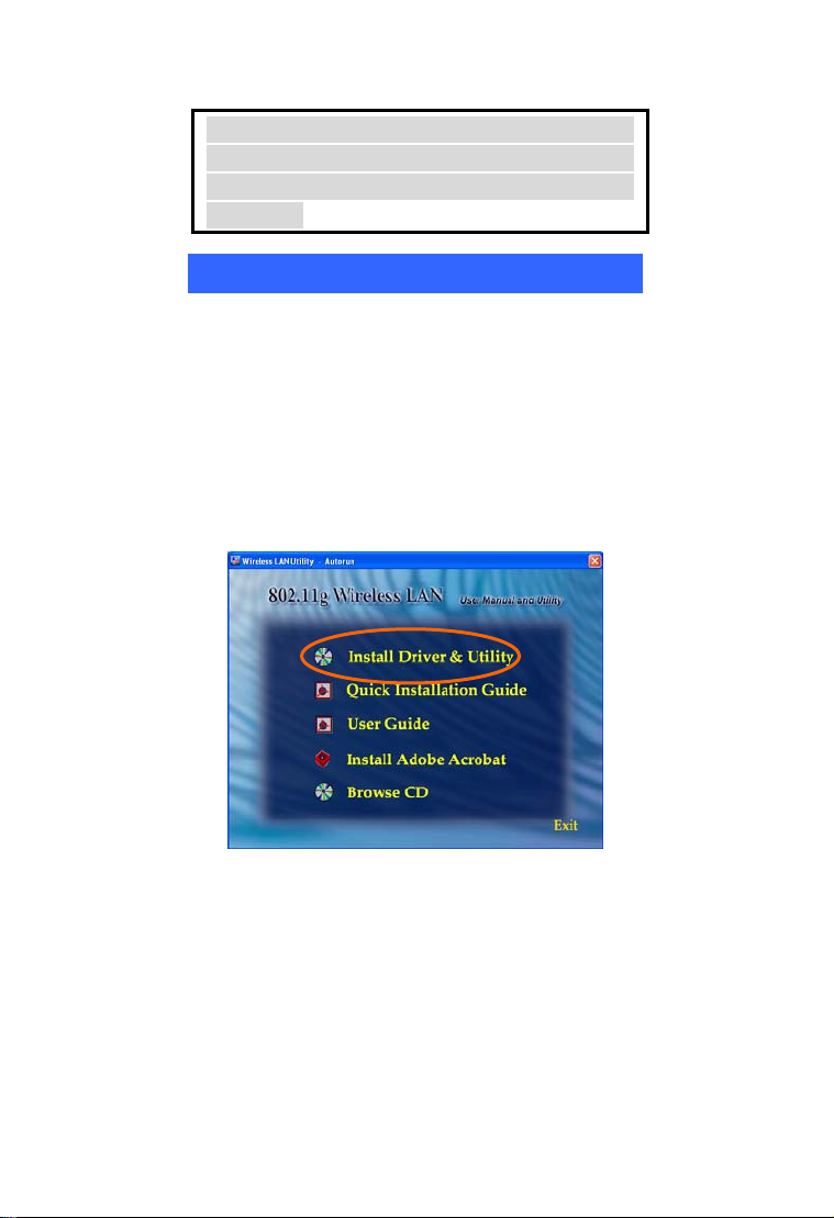
2. The main screen of the CD-ROM opens.
Click Install Driver & Utility to start the
installation.
3. When the Welcome screen appears, click
Next to continue.
- 1 - - 2 -
Page 3
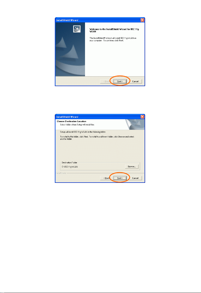
4. The Choose Destination Location screen
will show you the default destination chosen
by the utility. Click Next to continue.
5. Follow the instruction to select the program
folder. Click Next to continue.
Page 4
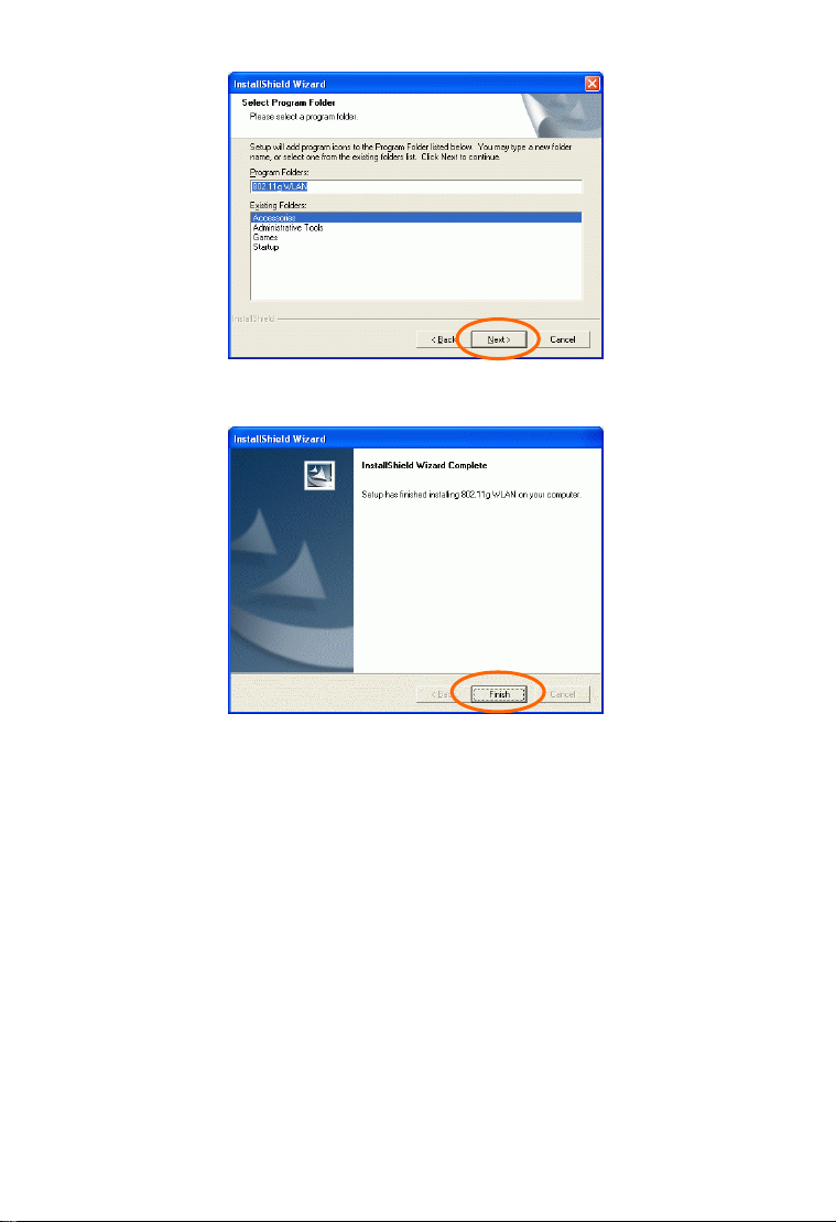
6. Click Finish to complete the installation
- 3 -
Page 5
Install the device
Note: Make sure the procedures in “Install the
Driver & Utility” has been performed.
1. If you are using the Wireless PCI Card, before
installing the device, make sure the computer
is turned off. Remove the expansion slot
cover from the computer. For Wireless
CardBus users, please locate your CardBus
slot.
2. Carefully slide the Wireless PCI/CardBus
Card into the PCI/CardBus slot. Push evenly
and slowly and ensure it is properly seated.
For Wireless PCI Card, you may have to use
the mounting screw to have the card screwed
securely in place.
3. After the device has been connected to your
computer, turn on your computer. Windows
will detect the new hardware and then
automatically copy all of the files needed for
networking. Recover your expansion slot
cover if you are using the Wireless PCI Card.
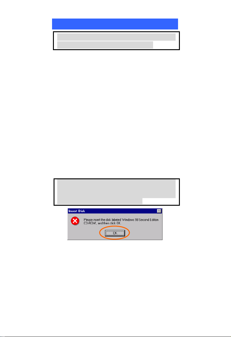
Note for Windows 98 users:
Before installation of the device, make sure you
have your operating system CD-ROM at hand.
You may be asked to insert the OS CD-ROM in
order to download specific drivers.
- 4 -
Page 6
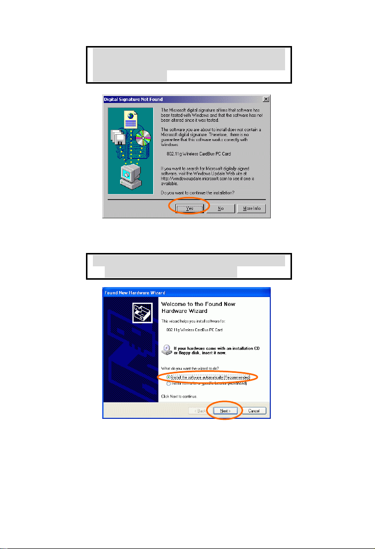
Note for Windows 2000 users:
During the installation, when the “Digital
Signature Not Found” screen appears, click
“Yes” to continue.
Note for Windows XP users:
1. Select Install the software automatically
(Recommended) and click Next.
- 5 - - 6 -
Page 7

3. Click Continue Anyway.
4. Click Finish to complete the installation.
Verify Device Installation
To verify that the device has been properly
installed in your computer and is enabled, go to
Start Æ Settings Æ Control Panel Æ System
(Æ Hardware) Æ Device Manager. Expand the
Network adapters item. If the 802.11g Wireless
Page 8

PCI/CardBus PC Card is listed, it means that
your device is properly installed and enabled.
CONFIGURATION
After successful installation of the Wireless LAN
Card’s driver, a Network Status icon will display
in the task bar. You will be able to access the
Configuration Utility through the Network Status
icon.
If the icon doesn’t appear automatically, go to
Start Æ Programs Æ 802.11g WLAN Æ
802.11g WLAN Utility, it will appear in the task
bar.
- 7 -
Page 9

The Network Status Icon
The Network Status Icon will display on the task bar
of your desktop and show the current network
connection status of your system.
Icon Link Status
Connected to network
Connecting
Driver not loaded
- 8 -
Page 10

Disconnected from network
Accessing the Configuration Utility
The Configuration Utility is accessed by clicking on the
Network Status Icon.
All settings are categorized into 5 Tabs:
Main Tab
Advanced Tab
Privacy Tab
Statistics Tab
About Tab
Main Tab
The Main tab displays the current status of the
Wireless Network Adapter.
- 9 -
Page 11

Item Description
External
Configuration
Status Displays the information about the
SSID The SSID is the unique name
To Enable or Disable the
manufacturer’s configuration utility:
Enable : Check this item to use
Windows XP build-in utility or other
manufacturers’, such as Funk,
Odyssey client utility.
Disable :Left this item unchecked to
use the utility we provide.
status of the communication.
shared among all points in your
wireless network.
The name must be identical for all
devices and points attempting to
connect to the same network.
No WEP key
With WEP key
For TI-Based WLAN devices
For TI-Based WLAN devices
Mode Displays the type of Basic Service
Ch Displays the channel that is
Signal Displays the signal strength of the
with WEP key
Set, Access Point or Peer to Peer.
currently in use.
connection between the Wireless
- 10 -
Page 12

Item Description
Network Adapter and the Access
BBS ID A set of wireless stations is referred
Current Configuration
Pref. SSID It shows the current SSID setting
BSS Type Displays the type of Basic Service
Channel Shows the selected channel that is
Tx Rate Shows the current transfer rate.
Signal Quality Displays the signal strength of the
BSSID the BSSID of the Access Point to
Connect
Modify There will be three tabs for you to
Rescan Searches for all available networks.
Point it connects to.
to as a Basic Service Set (BSS).
Computers in a BSS must be
configured with the same BSS ID.
of the Wireless Network Adapter.
Set, Access Point or Peer to Peer.
currently used. (There are 14
channels available, depends on the
country.)
connection between the Wireless
Network Adapter and the Access
Point it connects.
which the card is associated
Highlight one of the device from
the list area and press the Connect
button to access it.
modify, see the detailed
information on page 21.
Clicking on the button, the device
will start to rescan and list all
available sites.
- 11 -
Page 13

(B
-
y)
,
Preferred
SSID
BSS Type You can select Peer-to-Peer, Access Point
Tx Rate You can select the data rate or set to auto
Channel Select the channel depends on your
Power
Mode
IBSS
protection
4x Config Select to disable or enable the TI-Based 4x
Mode You can select IEEE 802.11b
Type in the SSID name of the device
you want to connect.
or Auto Mode of the device you to
connect.
mode from the pull-down menu.
country.
No Power Save:Select this function , the
adapter will be in full active mode.
Max Power Save:Select this function, the
power save mode will be enabled.
The 802.11g standard includes a
protection mechanism to ensure mixed
802.11b and 802.11g operation. If there
is no such kind of mechanism exists, the
two kinds of standards may mutually
interfere and decrease network’s
performance.
NONE:if you select this item , then
there will be no any protection
provided.
CTS only:Used only in the co-existing
environment of 802.11b and 802.11g
protection mechanism.
function.
Onl
- 12 -
Page 14

802.11b +(B-Plus) ,802.11g (G-Only)standard
or B&G Mode (If you choose this option the
device will automatically convert the suitable
Profile Enter the profile name and click the
Tx Power
Level
standard ).
Save button to save your configuration,
To open the profiles you saved, select
the profile from the pull-down menu
and then click the Load button. To
delete the profiles you saved, select the
profile from the pull-down menu and
then click the Delete button.
Transmit power level, includes Low
Power, Medium-Low Power, Medium
Power, Medium-High Power, High
Power
Fragment
Threshold
RTS Threshold This value should remain at its
To fragment MSDU or MMPDU
into small sizes of frames for
increasing the reliability of frame
(The maximum value of 4096
means no fragmentation is
needed) transmission. The
performance will be decreased as
well, thus a noisy environment is
recommended.
default setting of 4096. Should
you encounter inconsistent data
flow, only minor modifications
- 13 -
Page 15

Preamble A preamble is a signal used in
Authentication The authentication type defines
Retry limits You can set the number of retries
Antennas To set the type of the antenna
802.11g version This section is enabled only with
of this value are recommended.
wireless environment to
synchronize the transmitting
timing including Synchronization
and Start frame delimiter. (Note:
If you want to change the
Preamble type into Long or
Short, please check the setting of
AP.)
configuration options for the
sharing of wireless networks to
verify identity and access
privileges of roaming wireless
network cards.
You may choose between Open
System, Shared Key, and Auto
Switch.
Open System: If the Access
Point is using "Open System"
authentication, then the wireless
adapter will need to be set to the
same authentication type.
Shared Key: Shared Key is
when both the sender and the
recipient share a secret key.
Auto Switch: Select Auto
Switch for the adapter to select
the Authentication type
automatically depending on the
Access Point Authentication
type.
if no acknowledgement appears
from the receiving station.
Tx Antenna:Antenna2 (Use the
factory default)
RX Antenna:Both (Use the
factory default)
G-Only Mode
- 14 -
Page 16

Advanced Tab
The Advanced tab displays the current status of
the Wireless Network Adapter.
Privacy Tab
Use the Privacy Tab to configure your WEP and
CCX settings. WEP (Wired Equivalent Privacy)
and CCX ( Cisco Compatible Extension )
encryption can be used to ensure the security of
your wireless network.
If you left External Configuration unchecked in
the Main tab(see page 9), functions in the
following figure will be enabled.
- 15 -
Page 17

If you checked External Configuration in the
Main tab(see page 10), functions in the following
figure will be disabled.
Privacy Mode Configure your NONE 、 WEP or
CCX settings:
NONE:No security defined.
WEP (Wired Equivalent Privacy) is
a data security mechanism based on a
40 Bit/128 Bit/256 Bit shared key
algorithm. Press the Select button to
change WEP configuration. A new
dialog window will be opened(see
page 26)
- 16 -
Page 18

y
CCX ( Cisco Compatible
Extension
centralized authentication, as well as
per-user wired equivalent privacy
(WEP) session keys. Press the Select
button to change CCX configuration.
A new dialog window will be opened.
(see page 27)
WEP Configuration
Encryption
1-4
To configure your WEP settings.
WEP (Wired Equivalent Privacy)
encryption can be used to ensure the
security of your wireless network.
Select one Key and Key Size then fill
in the appropriate value/phrase in
Encryption field. Note: You must use
the same Key and Encryption settings
for the both sides of the wireless
network to connect
KEY1 ~ KEY 4:You can specify up
to 4 different keys to decrypt wireless
data. Select the Default key setting
from the radio button.
Encryption : This setting is the
configuration key used in accessing
the wireless network via WEP
encryption.
A key of 10 hexadecimal characters
(0-9, A-F) is required if a 64-bit Key
Length was selected.
A ke
). It provides user-based,
of 26 hexadecimal characters
- 17 -
Page 19

(0-9, A-F) is required if a 128-bit Key
Length was selected.
A key of 58 hexadecimal characters
(0-9, A-F) is required if a 256-bit Key
Length was selected.
Key size 40 Bit, 128 Bit or 256 Bit.
CCX Configuration
Network
Security Type
LEAP User
Network administers have been taking advantage of the
simplified user and security administration that LEAP
provides.
Before the security authentication is started, you should
enter the user name and password or the authentication
process will fail.
None – Choosing it will enable the
WEP Select button. As described in
Page 26.
LEAP – Choosing it will enable the
LEAP security.
External – Select this item to use the
external CCX configuration utility.
Statistics Tab
The Statistics Tab displays the available statistic
information including Receive packets, Transmit
packets, Association reject packets, Association
- 18 -
Page 20

timeout packets, Authentication reject packets,
Authentication timeout packets.
About Tab
Click on the About tab to view basic version
information about the OS Version, Utility Version,
Driver Version, Firmware Version and EEPROM
Version.
- 19 -
 Loading...